EP1950413A2 - Recoil starter - Google Patents
Recoil starter Download PDFInfo
- Publication number
- EP1950413A2 EP1950413A2 EP08000969A EP08000969A EP1950413A2 EP 1950413 A2 EP1950413 A2 EP 1950413A2 EP 08000969 A EP08000969 A EP 08000969A EP 08000969 A EP08000969 A EP 08000969A EP 1950413 A2 EP1950413 A2 EP 1950413A2
- Authority
- EP
- European Patent Office
- Prior art keywords
- rope reel
- cam
- rope
- ratchet
- reel
- Prior art date
- Legal status (The legal status is an assumption and is not a legal conclusion. Google has not performed a legal analysis and makes no representation as to the accuracy of the status listed.)
- Granted
Links
Images


Classifications
-
- F—MECHANICAL ENGINEERING; LIGHTING; HEATING; WEAPONS; BLASTING
- F02—COMBUSTION ENGINES; HOT-GAS OR COMBUSTION-PRODUCT ENGINE PLANTS
- F02N—STARTING OF COMBUSTION ENGINES; STARTING AIDS FOR SUCH ENGINES, NOT OTHERWISE PROVIDED FOR
- F02N3/00—Other muscle-operated starting apparatus
- F02N3/02—Other muscle-operated starting apparatus having pull-cords
-
- F—MECHANICAL ENGINEERING; LIGHTING; HEATING; WEAPONS; BLASTING
- F02—COMBUSTION ENGINES; HOT-GAS OR COMBUSTION-PRODUCT ENGINE PLANTS
- F02N—STARTING OF COMBUSTION ENGINES; STARTING AIDS FOR SUCH ENGINES, NOT OTHERWISE PROVIDED FOR
- F02N15/00—Other power-operated starting apparatus; Component parts, details, or accessories, not provided for in, or of interest apart from groups F02N5/00 - F02N13/00
- F02N15/02—Gearing between starting-engines and started engines; Engagement or disengagement thereof
- F02N15/022—Gearing between starting-engines and started engines; Engagement or disengagement thereof the starter comprising an intermediate clutch
- F02N15/027—Gearing between starting-engines and started engines; Engagement or disengagement thereof the starter comprising an intermediate clutch of the pawl type
-
- F—MECHANICAL ENGINEERING; LIGHTING; HEATING; WEAPONS; BLASTING
- F02—COMBUSTION ENGINES; HOT-GAS OR COMBUSTION-PRODUCT ENGINE PLANTS
- F02N—STARTING OF COMBUSTION ENGINES; STARTING AIDS FOR SUCH ENGINES, NOT OTHERWISE PROVIDED FOR
- F02N5/00—Starting apparatus having mechanical power storage
- F02N5/02—Starting apparatus having mechanical power storage of spring type
Definitions
- An aspect of the present invention relates to a recoil starter for starting an engine.
- recoil starter structured such that a recoil rope wound around a rope reel is pulled to thereby rotate a rope reel.
- the rotation power of a cam to be rotated by the rotation of the rope reel is transmitted through a clutch mechanism such as a centrifugal clutch to a rotary member such as a flywheel magnet or a drive pulley connected to the crank shaft of an engine.
- the crank shaft of the engine is rotated through the rotary member to thereby start the engine.
- This type of recoil starter includes a shock absorbing and power storing member interposed between the rope reel and cam.
- the shock absorbing and power storing member is used to prevent an impact due to a sudden variation in a load on the engine side from being transmitted to the rope reel side.
- the rotation power of the rope reel is stored in the shock absorbing and power storing member, and the rotation power stored in the shock absorbing and power storing member is released to thereby facilitate the start of the engine (for example, see JP-A-2001-132591 ).
- Above-mentioned mechanism is structured such that, the rope reel to be rotated by pulling the recoil rope, the cam for transmitting the rotation power of the rope reel through the clutch mechanism to the drive pulley connected to the crank shaft of the engine, and a spring case storing therein a spring serving as the shock absorbing and power storing member are respectively rotatably supported by a support shaft provided within the case. Between the rope reel and spring case, there is interposed a one-way ratchet mechanism to thereby be able to transmit the engine start direction rotation power of the rope reel to the spring case.
- the spring case When the rope reel is rotated by pulling the recoil rope, the spring case is rotated integrally with the rope reel through the one-way direction ratchet mechanism to transmit the rotation power of the rope reel to the drive pulley through the spring case.
- the rotation power of the rope reel can be stored in the spring.
- a one-way clutch is disposed between the support shaft and spring case.
- the spring case storing therein the spring serving as the shock absorbing and power storing member, the rope reel having the recoil rope wound thereon, and the drive pulley for transmitting the rotation power of the rope reel to the crank shaft of the engine are respectively rotatably supported on the support shaft disposed within the case, between the rope reel and spring case, there is interposed the one-way ratchet mechanism for transmitting the rotation power of the rope reel in the engine start direction to the spring case, and between the spring case and support shaft, there is interposed the one-way clutch for rotating the spring case only in the engine start direction.
- the number of parts is large and the structure is complicated. This results not only in the expensive cost of the recoil starter but also in the increased dimension of the outside diameter shape thereof, especially, the increased axial direction dimension thereof, which retards the downsizing and weight reduction of the recoil starter.
- An object of the prevent invention is to provide a recoil starter capable of easily starting an engine and to reduce the number of parts to thereby reduce the cost, size and weight of the recoil starter.
- a recoil starter including: a case that is disposed on an engine and that includes a reel support shaft formed thereon; a rope reel rotatably disposed on the reel support shaft; a recoil rope wound on an outer peripheral portion of the rope reel to rotate the rope reel in an engine start direction; a recoil spring that rotationally energizes the rope reel in an opposite direction of the engine start direction to rewind the recoil rope; a cam engaged with a drive pulley connected to an engine through a clutch mechanism to transmit an rotation power of the rope reel to the drive pulley; a power storing spring interposed between the rope reel and the cam; and a ratchet mechanism interposed between the rope reel and the cam; wherein the ratchet mechanism separates the rope reel and the cam from each other when the rope reel is rotated in the engine start direction; wherein the ratchet mechanism connects together the rope reel and the cam when the rope reel is rotated in the opposite direction to the engine start direction;
- the inner peripheral surface of the case may include uneven surfaces successively formed thereon.
- the inner peripheral surface of the case may include a plurality of concaves successively formed thereon at intervals.
- a recoil starter including: a case including: a reel support shaft formed thereon, and an inner peripheral surface formed unevenly; a rope reel rotatably disposed on the reel support shaft; a recoil rope wound on an outer peripheral portion of the rope reel to rotate the rope reel in an engine start direction; a recoil spring that rotationally energizes the rope reel in an opposite direction of the engine start direction; a cam that is configured to be engaged with an engine through a clutch mechanism and that has a recess disposed on an outer peripheral portion thereof; a power storing spring interposed between the rope reel and the cam; a ratchet shaft formed on the rope reel; a ratchet member including: a base portion that is formed on one end of the ratchet member and that has an elongated hole to be oscillatably connected with the ratchet shaft, and a ratchet pawl formed on the other end of the ratchet member to be engaged with the recess of
- Fig. 1 shows a longitudinal side section view of a recoil starter according to an embodiment.
- a case 1 of the recoil starter is structured so as to store the main structure of the recoil starter thereinside and cover the side surface portion of an engine.
- a reel support shaft 2 is provided on an inside surface of the case 1, in such a manner that it is opposed to the crank shaft (not shown) of the engine.
- a rope reel 4 is rotatably mounted on the outer periphery of the rope reel 4, a recoil rope 3 is wound.
- the recoil rope 3 is wound on the reel portion 4a of the rope reel 4 formed on the outer periphery thereof.
- the one end side of the recoil rope 3 is fixed to the rope reel 4.
- the other end side of the recoil rope 3 is drawn out externally of the case 1 (see Fig. 2 ).
- the rope reel 4 can be driven and rotated about the reel support shaft 2.
- a cam 6 including a cam piece 6a provided on the outer peripheral surface thereof, while the cam piece 6a can be engaged with a clutch mechanism provided on a drive pulley (not shown) which is to be mounted on the crank shaft of the engine.
- the cam 6 is rotatably supported on the reel support shaft 2 together with the rope reel 4 by a screw 7 which is threadedly engaged with the end portion of the reel support shaft 2.
- the clutch mechanism provided on the drive pulley is structured as a centrifugal clutch mechanism including a centrifugal ratchet (not shown) which is rotated and energized by a spring in the direction of the cam piece 6a provided on the cam 6.
- a centrifugal ratchet (not shown) which is rotated and energized by a spring in the direction of the cam piece 6a provided on the cam 6.
- the centrifugal ratchet (not shown) is rotated due to a centrifugal force against the spring energizing force and is separated apart from the cam piece 6a to thereby prevent the rotation power from the engine side from being transmitted to the recoil starter side.
- a recessed portion 8 in the side surface of the rope reel 4 on the opposite side of the reel portion 4a, there is formed a recessed portion 8.
- a power storing spring 10 which constitutes shock absorbing and power storing member.
- the power storing spring 10, which is stored within the recessed portion 8, is structured such that one end of the outer peripheral side thereof is fixed to the ring-shaped inner peripheral surface 9 of the recessed portion 8 and the end portion of the inner peripheral side thereof is engaged with the cam 6.
- the rope reel 4 and cam 6 are connected together through the power storing spring 10, and the rotation power of the rope reel 4 is transmitted through the power storing spring 10 to the cam 6.
- the engine start resistance prevents the rotation of the cam 6 to generate relative rotation between the cam 6 and rope reel 4, whereby the rotation power of the rope reel 4 is stored into the power storing spring 10.
- a ratchet mechanism 11 which, when the rope reel 4 is rotated in the engine start direction (the arrow mark direction in Fig. 2 ), is separated from the rope reel 4 and, when the rope reel 4 is rotated in the opposite direction to the engine start direction, is engaged with the rope reel 4 to thereby rotate the cam 6 integrally with the rope reel 4 in the opposite direction to the engine start direction.
- the ratchet mechanism 11 is composed of a ratchet member 13 which is oscillatably supported on a support shaft 12 provided on the side surface of the outer peripheral portion of the rope reel 4.
- a ratchet pawl 13a provided on the leading end of the ratchet member 13 is engaged with one of the engaging surfaces 6c of an engaging member 6b provided on the outer peripheral surface of the cam 6, the cam 6 can be rotated integrally with the rope reel 4 in the opposite direction to the engine start direction.
- the ratchet member 13 as can be understood from Figs. 2 and so on, includes an elongated hole 13c formed in its base portion 13b.
- the ratchet member 13 is supported such that, when the elongated hole 13c of the base portion 13b is fitted over the support shaft 12, the ratchet member 13 can be rotated with the support shaft 12 as its rotation fulcrum X and also can be slided through the elongated hole 13c of the base portion 13b.
- the sliding movement of the ratchet member 13 using the elongated hole 13c of the base portion 13b is such movement that allows the relative movement of the rotation fulcrum X of the ratchet member 13 substantially in the diameter direction thereof; and, in order to attain the relative movement of the rotation fulcrum X in the substantial diameter direction, the elongated hole 13c is formed in the above-mentioned one end base portion 13b as a hole which, when the ratchet member 13 is provide in the above-mentioned manner, is allowed to extend long substantially in the diameter direction.
- the base portion 13b of the ratchet member 13 has a substantially hexagonal shape; and, the outside thereof, that is, a corner portion 13d thereof facing the inner peripheral portion side of the case 1 or the two forming surfaces 13e, 13f of the corner portion 13d are energized by a spring 14 in such a manner that it or they can be slidingly contacted with the sliding surface 1a of the inner peripheral surface of the case 1.
- each uneven surface is composed of a peripheral surface 1a and an arc-shaped recessed portion 1b.
- a projection-shaped oscillation restrict portion 4d which restricts the oscillation angle of the ratchet pawl 13a provided on the leading end of the ratchet member 13.
- the ratchet member 13 is rotated integrally with the rope reel 4: that is, the ratchet member 13 rotates in such a manner that the corner portion 13b and its forming surfaces 13e, 13f respectively energized by the spring 14 are in sliding contact with the arc-shaped recessed portion 1b and peripheral surface 1a of the inner peripheral portion of the case 1.
- the ratchet member 13 is oscillated through the alternate sliding contact movements of the corner portion 13d of the base portion 13b or the corner portion forming surfaces 13e, 13f with the arc-shaped recessed portion 1b and peripheral surface 1a.
- the oscillation state of the ratchet member 13 varies variously.
- the ratchet member 13 As the rope reel 4 is rotated, the ratchet member 13 is allowed to move in the diameter direction with respect to the support shaft 12 due to the operation of the elongated hole 13c formed in the base portion 13b of one end portion of the ratchet member 13; and, this diameter direction movement of the ratchet member 13 changes the position of the rotation fulcrum X of the actually moving ratchet member 13 as well as the positions of the sliding contact points of the base portion corner portion 13d or corner portion forming surfaces 13e, 13f with the arc-shaped recessed portion 1b and peripheral surface 1a. That is, the oscillation state of the ratchet member 13 can vary according to the above-mentioned changes of the positions.
- the oscillation of the ratchet member 13 is large up to the limit of the allowable maximum oscillation angle between the position where the ratchet pawl 13a of the ratchet member 13 is engaged with the outer peripheral portion of the engaging member 6b of the cam 6 and the position where it is contacted with the oscillation restrict member 4d.
- the reason for this large oscillation is that the rope reel 4 rotates clockwise with respect to the case 1, and the base portion 13b of the ratchet member 13 is slidingly contacted with the peripheral surface 1a of the inner peripheral portion of the case 1 through the corner portion 13d and corner portion forming surface 13f, whereby the arc-shaped recessed portion 1b associated with the peripheral surface 1a rotates the ratchet member 13 counterclockwise about the support shaft 12.
- This large oscillatory movement of the ratchet member 13 is the movement that can engage the ratchet pawl 13a formed in leading end portion of the ratchet member 13 with the engaging member 6b of the cam 6.
- this large oscillatory movement of the ratchet member 13 is an operation by which, as will be discussed later, in a state where a load on the engine side is large and the rotation of the cam 6 is prevented, the ratchet pawl 13a for holding the stored power of the wound power storing spring 10 generated due to the mutual rotation between the rope reel 4 and cam 6 can be engaged with one of the engaging surfaces 6c of the engaging member 6b of the cam 6.
- the ratchet member 13 rotating integrally with the rope reel 4 is rotated while oscillating in such a manner that the outwardly facing corner portion 13d or the corner portion forming surfaces 13e, 13f of the spring energized base portion 13b is or are slidingly contacted with the sliding surface of the inner peripheral portion of the outer wall of the case 1 in which the arc-shaped recessed portion 1b and peripheral surface 1a are formed alternately and successively.
- This oscillatory movement of the ratchet member 13 is carried out while holding a state where the ratchet pawl 13a provided on the leading end portion of the ratchet member 13 remains in contact with the oscillation restrict member 4d.
- the oscillation of the ratchet member 13 in the above-mentioned rotation of the rope reel 4 is carried out in such a manner that, as described above, the ratchet pawl 13a is substantially held in contact with the oscillation restrict member 4d; and, therefore, there is no fear that the ratchet pawl 13a can be contacted with the outer peripheral portion of the engaging member 6b of the cam 6.
- the ratchet pawl 13a is engaged with the engaging surface 6c of the engaging member 6b of the cam 6. Therefore, the rope reel 4 and cam 6, while maintaining their relative positions shifted due to the above-mentioned their relative rotation, are connected together into an integral body, that is, while holding the stored power obtained by the winding of the power storing spring 10, the rope reel 4 and cam 6 are connected together into an integral body and, owing to the operation of the recoil spring 5, the integral body is rotated in the opposite direction, whereby the rope reel 4 is returned to its initial state.
- the above-mentioned operation to pull the recoil rope 3 is executed again to rotate the rope pulley 4 in the engine start direction to thereby increase the stored power of the power storing spring 10 further; and, using a rotation power based on the thus stored power, the cam 6 is rotated through the power storing spring 10 and is engaged with a centrifugal ratchet (not shown) to thereby start the engine again through the drive pulley.
- the start of the engine can be attained in a shock absorbed condition while making use of the shock absorbing and power storing operation simply by pulling the recoil rope 3 relatively short two or more times.
- the engine can also be started in a shock absorbed condition while making use of the shock absorbing and power storing operation by pulling the recoil rope 3 relatively long. In this manner, since the pulling length of the recoil rope 3 and the power applying position can be controlled, the engine can be started easily in a shock reduced manner while utilizing the shock absorbing power operation.
- the ratchet mechanism 11 is composed of the ratchet member 13 structured such that the base portion 13b formed in one end of the ratchet member 13 is supported oscillatably and slidably through the elongated hole 13c thereof on the side surface of the outer peripheral portion of the rope reel 4; and, the corner portion 13b formed on the outside of the one end base portion 13b of the ratchet member 13 or the forming surfaces 13e, 13f of the corner portion 13b is or are pressed and energized by an energizing member so that it or they can be slidingly contacted with the sliding surface of the inner peripheral surface of the outer wall of the case 1.
- the sliding surface includes the arc-shaped recessed portion 1b and peripheral surface 1a.
- the ratchet pawl 13a of the ratchet member 13 can be oscillated according to the rotation direction of the rope reel 4. Therefore, the ratchet pawl 13a can be positively engaged with or disengaged from the engaging member 6b of the cam 6, thereby being able to carry out a stable operation.
- the ratchet mechanism structured such that, when the rope reel is rotated in the engine start direction, it is separated from the cam and, when the rope reel is rotated in the opposite direction, it can be engaged with the cam to thereby rotate the cam in the opposite direction integrally with the rope reel.
- the present invention can eliminate not only a conventional rotary member such as a spring case which is interposed between the rope reel and cam and can be rotated independently, but also a conventional one-way clutch mechanism for allowing the rotation of the rotary member only in one direction. This can simplify the structure of the present recoil starter as well as can reduce the cost, size and weight thereof.
- the shock absorbing and power storing member is composed of a power storing spring having one end secured to the rope reel with the other end secured to the cam, the shock absorbing capability of the shock absorbing and power storing member can set large and thus there can be provided a large shock absorbing effect, which makes it possible to start the engine more smoothly. And, the power storing capability thereof can also be set large, whereby a rotation power necessary to start the engine can be stored sufficiently.
- the ratchet mechanism is composed of the ratchet member the one end base portion of which is supported oscillatably and slidably through the elongated hole on the side surface of the outer peripheral portion of the rope reel, and the one end base portion of the ratchet member can be pushed and energized by the energizing member such that it can be slidingly contacted with the inner peripheral surface of the outer wall of the case.
- the ratchet pawl provided on the leading end of the ratchet member can be accurately engaged with and disengaged from the engaging member of the cam, whereby the recoil starter can be operated stably with high reliability.
- the ratchet member is allowed to oscillate while it is in sliding contact with the above-mentioned inner peripheral surface.
- the uneven surfaces of the case are composed of the arc-shaped recessed portions which are formed successively at intervals in the inner peripheral surface of the case, the oscillatory motion of the ratchet member, which oscillates in sliding contact with the above-mentioned inner peripheral surface, is accurate, stable and regular. This can enhance further the accuracy of the engagement and disengagement of the ratchet pawl with respect to the cam engaging member according to the rotation direction of the rope reel.
Landscapes
- Engineering & Computer Science (AREA)
- Chemical & Material Sciences (AREA)
- Combustion & Propulsion (AREA)
- Mechanical Engineering (AREA)
- General Engineering & Computer Science (AREA)
- Transmission Devices (AREA)
- Springs (AREA)
Abstract
Description
- The entire disclosure of
Japanese Patent Application No.2007-014237 filed on January 24, 2007 - An aspect of the present invention relates to a recoil starter for starting an engine.
- There is known a recoil starter structured such that a recoil rope wound around a rope reel is pulled to thereby rotate a rope reel. The rotation power of a cam to be rotated by the rotation of the rope reel is transmitted through a clutch mechanism such as a centrifugal clutch to a rotary member such as a flywheel magnet or a drive pulley connected to the crank shaft of an engine. The crank shaft of the engine is rotated through the rotary member to thereby start the engine. This type of recoil starter includes a shock absorbing and power storing member interposed between the rope reel and cam. The shock absorbing and power storing member is used to prevent an impact due to a sudden variation in a load on the engine side from being transmitted to the rope reel side. The rotation power of the rope reel is stored in the shock absorbing and power storing member, and the rotation power stored in the shock absorbing and power storing member is released to thereby facilitate the start of the engine (for example, see
JP-A-2001-132591 - Above-mentioned mechanism is structured such that, the rope reel to be rotated by pulling the recoil rope, the cam for transmitting the rotation power of the rope reel through the clutch mechanism to the drive pulley connected to the crank shaft of the engine, and a spring case storing therein a spring serving as the shock absorbing and power storing member are respectively rotatably supported by a support shaft provided within the case. Between the rope reel and spring case, there is interposed a one-way ratchet mechanism to thereby be able to transmit the engine start direction rotation power of the rope reel to the spring case. When the rope reel is rotated by pulling the recoil rope, the spring case is rotated integrally with the rope reel through the one-way direction ratchet mechanism to transmit the rotation power of the rope reel to the drive pulley through the spring case. When the rotation of the drive pulley is caused to stop due to the start resistance of the engine, the rotation power of the rope reel can be stored in the spring. In order to prevent the spring case from rotating in the opposite direction, a one-way clutch is disposed between the support shaft and spring case.
- According to the above-mentioned technology, the spring case storing therein the spring serving as the shock absorbing and power storing member, the rope reel having the recoil rope wound thereon, and the drive pulley for transmitting the rotation power of the rope reel to the crank shaft of the engine are respectively rotatably supported on the support shaft disposed within the case, between the rope reel and spring case, there is interposed the one-way ratchet mechanism for transmitting the rotation power of the rope reel in the engine start direction to the spring case, and between the spring case and support shaft, there is interposed the one-way clutch for rotating the spring case only in the engine start direction. Thus, the number of parts is large and the structure is complicated. This results not only in the expensive cost of the recoil starter but also in the increased dimension of the outside diameter shape thereof, especially, the increased axial direction dimension thereof, which retards the downsizing and weight reduction of the recoil starter.
- An object of the prevent invention is to provide a recoil starter capable of easily starting an engine and to reduce the number of parts to thereby reduce the cost, size and weight of the recoil starter.
- According to an aspect of the present invention, there is provided a recoil starter including: a case that is disposed on an engine and that includes a reel support shaft formed thereon; a rope reel rotatably disposed on the reel support shaft; a recoil rope wound on an outer peripheral portion of the rope reel to rotate the rope reel in an engine start direction; a recoil spring that rotationally energizes the rope reel in an opposite direction of the engine start direction to rewind the recoil rope; a cam engaged with a drive pulley connected to an engine through a clutch mechanism to transmit an rotation power of the rope reel to the drive pulley; a power storing spring interposed between the rope reel and the cam; and a ratchet mechanism interposed between the rope reel and the cam; wherein the ratchet mechanism separates the rope reel and the cam from each other when the rope reel is rotated in the engine start direction; wherein the ratchet mechanism connects together the rope reel and the cam when the rope reel is rotated in the opposite direction to the engine start direction; wherein the ratchet mechanism includes: a support shaft formed on a side surface of the rope reel, a ratchet member having: a base portion formed in one end portion thereof as is oscillatably and slidably supported through an elongated hole on the support shaft, and a ratchet pawl formed on the other end portion thereof and engageable with an engaging portion disposed on an outer peripheral portion of the cam, and an energizer that energizes the base portion so that the base portion is slidingly contacted with an inner peripheral surface of the case.
- The inner peripheral surface of the case may include uneven surfaces successively formed thereon.
- The inner peripheral surface of the case may include a plurality of concaves successively formed thereon at intervals.
- According to another aspect of the present invention, there is provided a recoil starter including: a case including: a reel support shaft formed thereon, and an inner peripheral surface formed unevenly; a rope reel rotatably disposed on the reel support shaft; a recoil rope wound on an outer peripheral portion of the rope reel to rotate the rope reel in an engine start direction; a recoil spring that rotationally energizes the rope reel in an opposite direction of the engine start direction; a cam that is configured to be engaged with an engine through a clutch mechanism and that has a recess disposed on an outer peripheral portion thereof; a power storing spring interposed between the rope reel and the cam; a ratchet shaft formed on the rope reel; a ratchet member including: a base portion that is formed on one end of the ratchet member and that has an elongated hole to be oscillatably connected with the ratchet shaft, and a ratchet pawl formed on the other end of the ratchet member to be engaged with the recess of the cam when the rope reel rotates in the opposite direction; and an energizer that energizes the base portion so that the base portion is slidingly contacted with the inner peripheral surface.
- Embodiments may be described in detail with reference to the accompanying drawings, in which:
-
Fig. 1 shows a longitudinal side section view of a recoil starter according to an embodiment; -
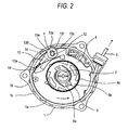
Fig. 2 shows the operation of a ratchet mechanism of the recoil starter according to the embodiment in a state where a recoil rope is pulled and a rope reel is thereby rotated in an engine start direction relative to a cam when the cam is stopped; -
Fig. 3 shows the operation of the ratchet mechanism of the recoil starter in a state just after the pulled-out recoil rope is rewound and the rope reel is thereby started to rotate in the opposite direction to the engine start direction relative to the cam when the cam is stopped; -
Fig. 4 shows the operation of the ratchet mechanism of the recoil starter in a state just before the oscillating ratchet pawl of a ratchet member is in contact with the engaging surface of the cam; -
Fig. 5 shows the operation of the ratchet mechanism of the recoil starter in a state where the ratchet pawl is engaged with the engaging surface and the relative rotation of the rope reel and cam is prevented; and -
Fig. 6 shows the operation of the ratchet mechanism of the recoil starter in a state where the rope reel and the cam are engaged with each other. - Description will be given below of an embodiment according to the invention with reference to
Figs. 1 to 6 .Fig. 1 shows a longitudinal side section view of a recoil starter according to an embodiment. As shown inFig. 1 , acase 1 of the recoil starter is structured so as to store the main structure of the recoil starter thereinside and cover the side surface portion of an engine. On an inside surface of thecase 1, areel support shaft 2 is provided in such a manner that it is opposed to the crank shaft (not shown) of the engine. On thereel support shaft 2, arope reel 4 is rotatably mounted. On the outer periphery of therope reel 4, arecoil rope 3 is wound. - The
recoil rope 3 is wound on thereel portion 4a of therope reel 4 formed on the outer periphery thereof. The one end side of therecoil rope 3 is fixed to therope reel 4. The other end side of therecoil rope 3 is drawn out externally of the case 1 (seeFig. 2 ). When the other end side of therecoil rope 3 is pulled, therope reel 4 can be driven and rotated about thereel support shaft 2. - Between the side surface of the
rope reel 4 and the outer peripheral surface of the base portion of thereel support shaft 2 provided on the inner surface of thecase 1, there is interposed arecoil spring 5 for rotating therope reel 4, which has been rotated in the engine start direction by pulling therecoil rope 3, in the opposite direction to the engine start direction to thereby rewind therecoil rope 3 drawn out from thereel portion 4a onto therope reel 4 again. - One end portion of the inner peripheral side of the
recoil spring 5 is fixed to thereel support shaft 2, while the other end portion of the outer peripheral side thereof is fixed to therope reel 4. When therecoil roper 3 is pulled to thereby rotate therope reel 4 in the engine start direction, a rotation power is stored in therecoil spring 5. Using a rotation power stored in therecoil spring 5 by releasing therecoil rope 3, therope reel 4 is rotated in the opposite direction to thereby rewind the recoil rope, 3 which has been drawn out externally of thecase 1, onto therope reel 4 again. - On the leading end side of the
reel support shaft 2, there is rotatably mounted acam 6 including acam piece 6a provided on the outer peripheral surface thereof, while thecam piece 6a can be engaged with a clutch mechanism provided on a drive pulley (not shown) which is to be mounted on the crank shaft of the engine. Thecam 6 is rotatably supported on thereel support shaft 2 together with therope reel 4 by ascrew 7 which is threadedly engaged with the end portion of thereel support shaft 2. - The clutch mechanism provided on the drive pulley (not shown) is structured as a centrifugal clutch mechanism including a centrifugal ratchet (not shown) which is rotated and energized by a spring in the direction of the
cam piece 6a provided on thecam 6. When thecam 6 is rotated in the engine start direction, the centrifugal ratchet is engaged with thecam piece 6a to thereby rotate the drive pulley in the engine start direction. - When the engine is started and the drive pulley is rotated through the crank shaft (not shown), the centrifugal ratchet (not shown) is rotated due to a centrifugal force against the spring energizing force and is separated apart from the
cam piece 6a to thereby prevent the rotation power from the engine side from being transmitted to the recoil starter side. - As shown in
Fig. 1 , in the side surface of therope reel 4 on the opposite side of thereel portion 4a, there is formed arecessed portion 8. In thisrecessed portion 8, there is stored a power storingspring 10 which constitutes shock absorbing and power storing member. The power storingspring 10, which is stored within therecessed portion 8, is structured such that one end of the outer peripheral side thereof is fixed to the ring-shaped innerperipheral surface 9 of therecessed portion 8 and the end portion of the inner peripheral side thereof is engaged with thecam 6. - The
rope reel 4 andcam 6 are connected together through thepower storing spring 10, and the rotation power of therope reel 4 is transmitted through thepower storing spring 10 to thecam 6. The engine start resistance prevents the rotation of thecam 6 to generate relative rotation between thecam 6 andrope reel 4, whereby the rotation power of therope reel 4 is stored into thepower storing spring 10. - As shown in
Figs. 1 ,2 and so on, between thecam 6 andrope reel 4, there is interposed aratchet mechanism 11 which, when therope reel 4 is rotated in the engine start direction (the arrow mark direction inFig. 2 ), is separated from therope reel 4 and, when therope reel 4 is rotated in the opposite direction to the engine start direction, is engaged with therope reel 4 to thereby rotate thecam 6 integrally with therope reel 4 in the opposite direction to the engine start direction. - The
ratchet mechanism 11 is composed of aratchet member 13 which is oscillatably supported on asupport shaft 12 provided on the side surface of the outer peripheral portion of therope reel 4. When aratchet pawl 13a provided on the leading end of theratchet member 13 is engaged with one of theengaging surfaces 6c of anengaging member 6b provided on the outer peripheral surface of thecam 6, thecam 6 can be rotated integrally with therope reel 4 in the opposite direction to the engine start direction. - The
ratchet member 13, as can be understood fromFigs. 2 and so on, includes anelongated hole 13c formed in itsbase portion 13b. Theratchet member 13 is supported such that, when theelongated hole 13c of thebase portion 13b is fitted over thesupport shaft 12, theratchet member 13 can be rotated with thesupport shaft 12 as its rotation fulcrum X and also can be slided through theelongated hole 13c of thebase portion 13b. The sliding movement of theratchet member 13 using theelongated hole 13c of thebase portion 13b is such movement that allows the relative movement of the rotation fulcrum X of theratchet member 13 substantially in the diameter direction thereof; and, in order to attain the relative movement of the rotation fulcrum X in the substantial diameter direction, theelongated hole 13c is formed in the above-mentioned oneend base portion 13b as a hole which, when theratchet member 13 is provide in the above-mentioned manner, is allowed to extend long substantially in the diameter direction. - The
base portion 13b of theratchet member 13 has a substantially hexagonal shape; and, the outside thereof, that is, acorner portion 13d thereof facing the inner peripheral portion side of thecase 1 or the two formingsurfaces corner portion 13d are energized by aspring 14 in such a manner that it or they can be slidingly contacted with thesliding surface 1a of the inner peripheral surface of thecase 1. - In the inner peripheral surface of the outer
peripheral portion 1c of thecase 1 with which thecorner portion 13d of thebase portion 13b of theratchet member 13 can be slidingly contacted, there are formed uneven surfaces successively. Each uneven surface is composed of aperipheral surface 1a and an arc-shaped recessedportion 1b. On the side surface edge portion of the outer peripheral portion of therope reel 4, there is provided a projection-shaped oscillation restrictportion 4d which restricts the oscillation angle of theratchet pawl 13a provided on the leading end of theratchet member 13. - Therefore, when the
rope reel 4 is rotated in the engine start direction by pulling therecoil rope 3, or when therope reel 4 is rotated in the opposite direction to the engine start direction by rewinding therecoil rope 3 which has been played out once, as shown inFigs. 2 ,3 and so on, theratchet member 13 is rotated integrally with the rope reel 4: that is, theratchet member 13 rotates in such a manner that thecorner portion 13b and its formingsurfaces spring 14 are in sliding contact with the arc-shaped recessedportion 1b andperipheral surface 1a of the inner peripheral portion of thecase 1. - Referring to the rotation of the
ratchet member 13, owing to the structure which allows theratchet member 13 to rotate and slide while it is supported on thesupport shaft 12 engaged with theelongated hole 13c of thebase portion 13b energized by thespring 14, theratchet member 13 is oscillated through the alternate sliding contact movements of thecorner portion 13d of thebase portion 13b or the cornerportion forming surfaces portion 1b andperipheral surface 1a. The oscillation state of theratchet member 13 varies variously. As therope reel 4 is rotated, theratchet member 13 is allowed to move in the diameter direction with respect to thesupport shaft 12 due to the operation of theelongated hole 13c formed in thebase portion 13b of one end portion of theratchet member 13; and, this diameter direction movement of theratchet member 13 changes the position of the rotation fulcrum X of the actually movingratchet member 13 as well as the positions of the sliding contact points of the baseportion corner portion 13d or cornerportion forming surfaces portion 1b andperipheral surface 1a. That is, the oscillation state of theratchet member 13 can vary according to the above-mentioned changes of the positions. - In the rotation of the
rope reel 4 in the engine start direction, while the oscillation of theratchet member 13 is small and theratchet pawl 13a in the leading end portion of theratchet member 13 is held in a state where it remains in contact with the oscillation restrictmember 4d. Such holding of the contact state is enabled by the fact that, therope reel 4 is rotated counterclockwise with respect to thecase 1 and thebase portion 13b of theratchet member 13 is slidingly contacted with theperipheral surface 1a of the inner peripheral portion of thecase 1 through thecorner portion 13d and cornerportion forming surface 13e to thereby allow the arc-shaped recessedportion 1b associated with theperipheral surface 1a to rotate theratchet member 13 clockwise about thesupport shaft 12. - On the other hand, in the rotation of the
rope reel 4 in the opposite direction to the engine start direction, the oscillation of theratchet member 13 is large up to the limit of the allowable maximum oscillation angle between the position where theratchet pawl 13a of theratchet member 13 is engaged with the outer peripheral portion of the engagingmember 6b of thecam 6 and the position where it is contacted with the oscillation restrictmember 4d. The reason for this large oscillation is that therope reel 4 rotates clockwise with respect to thecase 1, and thebase portion 13b of theratchet member 13 is slidingly contacted with theperipheral surface 1a of the inner peripheral portion of thecase 1 through thecorner portion 13d and cornerportion forming surface 13f, whereby the arc-shaped recessedportion 1b associated with theperipheral surface 1a rotates theratchet member 13 counterclockwise about thesupport shaft 12. This large oscillatory movement of theratchet member 13 is the movement that can engage theratchet pawl 13a formed in leading end portion of theratchet member 13 with the engagingmember 6b of thecam 6. - That is, this large oscillatory movement of the
ratchet member 13 is an operation by which, as will be discussed later, in a state where a load on the engine side is large and the rotation of thecam 6 is prevented, theratchet pawl 13a for holding the stored power of the woundpower storing spring 10 generated due to the mutual rotation between therope reel 4 andcam 6 can be engaged with one of the engagingsurfaces 6c of the engagingmember 6b of thecam 6. - Here, description will be given below of the operation of the recoil starter according to the above-mentioned embodiment with reference to
Figs. 2 to 5 . - By the way, in this type of recoil starter, by pulling the recoil rope, the rope reel is rotated in the engine start direction, the cam is rotated through the power storing spring, and the cam piece of the cam is engaged with the centrifugal ratchet to rotate the drive pulley to thereby rotate the crank shaft coupled to the drive pulley. When the rotation load of the drive pulley is increased due to the start resistance of the engine, the rotation of the drive pulley is caused to stop and the rotation of the cam contacted by the centrifugal clutch is also caused to stop; however, the rope reel is further rotated with respect to the cam the rotation of which is stopped, whereby the power storing spring is wound and thus the rotation power is stored into the power storing spring. An impact due to a sudden variation in the load on the engine side can be absorbed by the power storing spring.
- In this state, when rewinding the recoil rope which has been pulled out, the rope reel is rotated in the opposite direction to the engine start direction due to the rotation power stored in the power storing spring to thereby rewind the recoil rope.
- When pulling the
recoil rope 3, therope reel 4 is rotated counterclockwise in the drawings (in the engine start direction), theratchet member 13 rotating integrally with therope reel 4 is rotated while oscillating in such a manner that the outwardly facingcorner portion 13d or the cornerportion forming surfaces base portion 13b is or are slidingly contacted with the sliding surface of the inner peripheral portion of the outer wall of thecase 1 in which the arc-shaped recessedportion 1b andperipheral surface 1a are formed alternately and successively. This oscillatory movement of theratchet member 13 is carried out while holding a state where theratchet pawl 13a provided on the leading end portion of theratchet member 13 remains in contact with the oscillation restrictmember 4d. - When a rotation load due to the start resistance of the engine side is small and the rotation resistance of the
cam 6 is small, the rotation of therope reel 4 in the engine start direction is transmitted to thecam 6 through thepower storing spring 10 while almost not winding thepower storing spring 10. - On the other hand, as shown in
Fig. 2 , when the rotation load due to the start resistance of the engine side is large and the rotation of thecam 6 is prevented, the rotation power of therope reel 4 in the engine start direction is transmitted to thecam 6 while winding thepower storing spring 10. However, until the rotation power composed of the stored power generated by winding thepower storing spring 10 increases up to a given amount, thecam 6 cannot be rotated. That is, therope reel 4 andcam 6 rotate relative to each other and, owing to this rotation of therope reel 4, thepower storing spring 10 is wound to thereby store power therein. - The oscillation of the
ratchet member 13 in the above-mentioned rotation of therope reel 4 is carried out in such a manner that, as described above, theratchet pawl 13a is substantially held in contact with the oscillation restrictmember 4d; and, therefore, there is no fear that theratchet pawl 13a can be contacted with the outer peripheral portion of the engagingmember 6b of thecam 6. - In the power stored state of the
power storing spring 10 where therope reel 4 andcam 6 have been rotated relative to each other and thepower storing spring 10 has been thereby wound, as shown inFig. 3 , when the drawn-outrecoil rope 3 is rewound and therope pulley 4 is thereby rotated in the opposite direction to the engine start direction, as described above, the oscillation of theratchet member 13 in this rotation becomes large; and, therefore, immediately after this opposite direction rotation is started, as shown inFig. 4 , with the oscillatory movement of theratchet member 13, theratchet pawl 13a provided on the leading end portion of theratchet member 13 is contacted with the outer peripheral portion of the engagingmember 6b of thecam 6. - Following the above-mentioned contact of the
ratchet pawl 13a, as shown inFig. 5 , theratchet pawl 13a is engaged with the engagingsurface 6c of the engagingmember 6b of thecam 6. Therefore, therope reel 4 andcam 6, while maintaining their relative positions shifted due to the above-mentioned their relative rotation, are connected together into an integral body, that is, while holding the stored power obtained by the winding of thepower storing spring 10, therope reel 4 andcam 6 are connected together into an integral body and, owing to the operation of therecoil spring 5, the integral body is rotated in the opposite direction, whereby therope reel 4 is returned to its initial state. - Apart from a case where the engine can be started by pulling the
recoil rope 3 only one time, that is, when the engine cannot be started by such one-time recoil rope 3 pulling, the above-mentioned operation to pull therecoil rope 3 is executed again to rotate therope pulley 4 in the engine start direction to thereby increase the stored power of thepower storing spring 10 further; and, using a rotation power based on the thus stored power, thecam 6 is rotated through thepower storing spring 10 and is engaged with a centrifugal ratchet (not shown) to thereby start the engine again through the drive pulley. - At the then time, when the rotation power based on the stored power of the
power storing spring 10 does not yet exceed the start resistance of the engine, the reacting force of the engine start resistance is transmitted to thecam 6 to thereby prevent the rotation of thecam 6. However, as therecoil rope 3 is rewound, therope reel 4 is rotated again in the opposite direction to the engine start direction to bring theratchet pawl 13a of theratchet member 13 into engagement with the engagingmember 6b of thecam 6 to thereby increase the stored power of thepower storing spring 10; and, in this power increased state, by pulling therecoil rope 3 further again, the above-mentioned operation is executed repeatedly. - On the other hand, when the rotation power based on the stored power of the
power storing spring 10 exceeds the start resistance of the engine, the rotation power of therope reel 4 and the rotation power stored in thepower storing spring 10 are released and transmitted through thecam 6 to the drive pulley (not shown) to rotate the crank shaft at a burst, thereby starting the engine. - According to the recoil starter of the above-mentioned embodiment, the start of the engine can be attained in a shock absorbed condition while making use of the shock absorbing and power storing operation simply by pulling the
recoil rope 3 relatively short two or more times. The engine can also be started in a shock absorbed condition while making use of the shock absorbing and power storing operation by pulling therecoil rope 3 relatively long. In this manner, since the pulling length of therecoil rope 3 and the power applying position can be controlled, the engine can be started easily in a shock reduced manner while utilizing the shock absorbing power operation. - The
ratchet mechanism 11 is composed of theratchet member 13 structured such that thebase portion 13b formed in one end of theratchet member 13 is supported oscillatably and slidably through theelongated hole 13c thereof on the side surface of the outer peripheral portion of therope reel 4; and, thecorner portion 13b formed on the outside of the oneend base portion 13b of theratchet member 13 or the formingsurfaces corner portion 13b is or are pressed and energized by an energizing member so that it or they can be slidingly contacted with the sliding surface of the inner peripheral surface of the outer wall of thecase 1. The sliding surface includes the arc-shaped recessedportion 1b andperipheral surface 1a. In thisratchet mechanism 11, theratchet pawl 13a of theratchet member 13 can be oscillated according to the rotation direction of therope reel 4. Therefore, theratchet pawl 13a can be positively engaged with or disengaged from the engagingmember 6b of thecam 6, thereby being able to carry out a stable operation. - According to an aspect of the present invention, between the rope reel and cam, there is interposed the ratchet mechanism structured such that, when the rope reel is rotated in the engine start direction, it is separated from the cam and, when the rope reel is rotated in the opposite direction, it can be engaged with the cam to thereby rotate the cam in the opposite direction integrally with the rope reel. The present invention can eliminate not only a conventional rotary member such as a spring case which is interposed between the rope reel and cam and can be rotated independently, but also a conventional one-way clutch mechanism for allowing the rotation of the rotary member only in one direction. This can simplify the structure of the present recoil starter as well as can reduce the cost, size and weight thereof.
- Further, since the shock absorbing and power storing member is composed of a power storing spring having one end secured to the rope reel with the other end secured to the cam, the shock absorbing capability of the shock absorbing and power storing member can set large and thus there can be provided a large shock absorbing effect, which makes it possible to start the engine more smoothly. And, the power storing capability thereof can also be set large, whereby a rotation power necessary to start the engine can be stored sufficiently.
- Further, the ratchet mechanism is composed of the ratchet member the one end base portion of which is supported oscillatably and slidably through the elongated hole on the side surface of the outer peripheral portion of the rope reel, and the one end base portion of the ratchet member can be pushed and energized by the energizing member such that it can be slidingly contacted with the inner peripheral surface of the outer wall of the case. Thus, since the sliding contact point of the one end base portion of the ratchet member in the above-mentioned sliding contact operation can be set according to the rotation direction of the rope reel, the ratchet pawl provided on the leading end of the ratchet member can be accurately engaged with and disengaged from the engaging member of the cam, whereby the recoil starter can be operated stably with high reliability.
- Further, since the uneven surfaces successively formed in the inner peripheral surface of the case, the ratchet member is allowed to oscillate while it is in sliding contact with the above-mentioned inner peripheral surface.
- Further, since the uneven surfaces of the case are composed of the arc-shaped recessed portions which are formed successively at intervals in the inner peripheral surface of the case, the oscillatory motion of the ratchet member, which oscillates in sliding contact with the above-mentioned inner peripheral surface, is accurate, stable and regular. This can enhance further the accuracy of the engagement and disengagement of the ratchet pawl with respect to the cam engaging member according to the rotation direction of the rope reel.
- It is explicitly stated that all features disclosed in the description and/or the claims are intended to be disclosed separately and independently from each other for the purpose of original disclosure as well as for the purpose of restricting the claimed invention independent of the compositions of the features in the embodiments and/or the claims. It is explicitly stated that all value ranges or indications of groups of entities disclose every possible intermediate value or intermediate entity for the purpose of original disclosure as well as for the purpose of restricting the claimed invention, in particular as limits of value ranges.
Claims (4)
- A recoil starter comprising:a case that is disposed on an engine and that includes a reel support shaft formed thereon;a rope reel rotatably disposed on the reel support shaft;a recoil rope wound on an outer peripheral portion of the rope reel to rotate the rope reel in an engine start direction;a recoil spring that rotationally energizes the rope reel in an opposite direction of the engine start direction to rewind the recoil rope;a cam engaged with a drive pulley connected to an engine through a clutch mechanism to transmit an rotation power of the rope reel to the drive pulley;a power storing spring interposed between the rope reel and the cam; anda ratchet mechanism interposed between the rope reel and the cam;wherein the ratchet mechanism separates the rope reel and the cam from each other when the rope reel is rotated in the engine start direction;
wherein the ratchet mechanism connects together the rope reel and the cam when the rope reel is rotated in the opposite direction to the engine start direction;
wherein the ratchet mechanism includes:a support shaft formed on a side surface of the rope reel,a ratchet member having:a base portion formed in one end portion thereof as is oscillatably and slidably supported through an elongated hole on the support shaft, anda ratchet pawl formed on the other end portion thereof and engageable with an engaging portion disposed on an outer peripheral portion of the cam, anda energizer that energizes the base portion so that the base portion is slidingly contacted with an inner peripheral surface of the case. - The recoil starter according to claim 1, wherein the inner peripheral surface of the case includes uneven surfaces successively formed thereon.
- The recoil starter according to claim 1 or 2, wherein the inner peripheral surface of the case includes a plurality of concaves successively formed thereon at intervals.
- A recoil starter comprising:a case including:a reel support shaft formed thereon, andan inner peripheral surface formed unevenly; a rope reel rotatably disposed on the reel support shaft;a recoil rope wound on an outer peripheral portion of the rope reel to rotate the rope reel in an engine start direction;a recoil spring that rotationally energizes the rope reel in an opposite direction of the engine start direction;a cam that is configured to be engaged with an engine through a clutch mechanism and that has a recess disposed on an outer peripheral portion thereof;a power storing spring interposed between the rope reel and the cam;a ratchet shaft formed on the rope reel;a ratchet member including:a base portion that is formed on one end of the ratchet member and that has an elongated hole to be oscillatably connected with the ratchet shaft, anda ratchet pawl formed on the other end of the ratchet member to be engaged with the recess of the cam when the rope reel rotates in the opposite direction; anda energizer that energizes the base portion so that the base portion is slidingly contacted with the inner peripheral surface.
Applications Claiming Priority (1)
| Application Number | Priority Date | Filing Date | Title |
|---|---|---|---|
| JP2007014237A JP4792408B2 (en) | 2007-01-24 | 2007-01-24 | Recoil starter |
Publications (3)
| Publication Number | Publication Date |
|---|---|
| EP1950413A2 true EP1950413A2 (en) | 2008-07-30 |
| EP1950413A3 EP1950413A3 (en) | 2010-06-30 |
| EP1950413B1 EP1950413B1 (en) | 2013-08-21 |
Family
ID=39310974
Family Applications (1)
| Application Number | Title | Priority Date | Filing Date |
|---|---|---|---|
| EP08000969.9A Active EP1950413B1 (en) | 2007-01-24 | 2008-01-18 | Recoil starter |
Country Status (4)
| Country | Link |
|---|---|
| US (1) | US7650868B2 (en) |
| EP (1) | EP1950413B1 (en) |
| JP (1) | JP4792408B2 (en) |
| CN (1) | CN101230822B (en) |
Cited By (4)
| Publication number | Priority date | Publication date | Assignee | Title |
|---|---|---|---|---|
| EP2258452A1 (en) | 2009-06-05 | 2010-12-08 | Tom Smith | Gyroscopic exerciser |
| EP2194262A3 (en) * | 2008-12-03 | 2015-08-19 | Yamaha Hatsudoki Kabushiki Kaisha | Outboard motor |
| EP3147494A1 (en) * | 2015-09-22 | 2017-03-29 | Coza International Limited Hongkong | Dual source starter system for an engine |
| US10591004B2 (en) * | 2014-04-10 | 2020-03-17 | United Technologies Corporation | Damped anti-rotational systems |
Families Citing this family (5)
| Publication number | Priority date | Publication date | Assignee | Title |
|---|---|---|---|---|
| JP5261797B2 (en) * | 2009-02-17 | 2013-08-14 | スターテング工業株式会社 | Recoil starter |
| JP5428093B2 (en) * | 2009-08-29 | 2014-02-26 | スターテング工業株式会社 | Small engine starter |
| JP5833910B2 (en) * | 2011-12-19 | 2015-12-16 | スターテング工業株式会社 | Recoil starter mechanism |
| CN102817757B (en) * | 2012-05-07 | 2015-05-06 | 隆鑫通用动力股份有限公司 | Engine manual start assembly and engine thereof |
| CN103899464A (en) * | 2012-12-28 | 2014-07-02 | 何平 | Manual internal combustion engine starter |
Citations (2)
| Publication number | Priority date | Publication date | Assignee | Title |
|---|---|---|---|---|
| JP2001132591A (en) | 1999-08-25 | 2001-05-15 | Kioritz Corp | Starter device |
| JP2007014237A (en) | 2005-07-06 | 2007-01-25 | Kanebo Foods Ltd | Lactic acid bacteria-containing tableting chewing gum and method for producing the same |
Family Cites Families (7)
| Publication number | Priority date | Publication date | Assignee | Title |
|---|---|---|---|---|
| US1066014A (en) * | 1911-04-20 | 1913-07-01 | Jacob C Lombard | Engine-starter. |
| US2976959A (en) * | 1957-04-29 | 1961-03-28 | American Machine & Metals | Ratchet device |
| US5257685A (en) * | 1992-03-05 | 1993-11-02 | United Technologies Corporation | Pawl and ratchet clutch with shifting pawl |
| JPH09273568A (en) * | 1996-04-03 | 1997-10-21 | Car Mate Mfg Co Ltd | Ratchet device |
| JP3865299B2 (en) * | 2001-12-07 | 2007-01-10 | スターテング工業株式会社 | Recoil starter for starting internal combustion engines |
| JP4346922B2 (en) * | 2002-10-21 | 2009-10-21 | スターテング工業株式会社 | Recoil starter |
| JP4381280B2 (en) * | 2004-10-18 | 2009-12-09 | スターテング工業株式会社 | Recoil starter |
-
2007
- 2007-01-24 JP JP2007014237A patent/JP4792408B2/en active Active
-
2008
- 2008-01-18 US US12/016,254 patent/US7650868B2/en active Active
- 2008-01-18 EP EP08000969.9A patent/EP1950413B1/en active Active
- 2008-01-24 CN CN2008100087137A patent/CN101230822B/en active Active
Patent Citations (2)
| Publication number | Priority date | Publication date | Assignee | Title |
|---|---|---|---|---|
| JP2001132591A (en) | 1999-08-25 | 2001-05-15 | Kioritz Corp | Starter device |
| JP2007014237A (en) | 2005-07-06 | 2007-01-25 | Kanebo Foods Ltd | Lactic acid bacteria-containing tableting chewing gum and method for producing the same |
Cited By (4)
| Publication number | Priority date | Publication date | Assignee | Title |
|---|---|---|---|---|
| EP2194262A3 (en) * | 2008-12-03 | 2015-08-19 | Yamaha Hatsudoki Kabushiki Kaisha | Outboard motor |
| EP2258452A1 (en) | 2009-06-05 | 2010-12-08 | Tom Smith | Gyroscopic exerciser |
| US10591004B2 (en) * | 2014-04-10 | 2020-03-17 | United Technologies Corporation | Damped anti-rotational systems |
| EP3147494A1 (en) * | 2015-09-22 | 2017-03-29 | Coza International Limited Hongkong | Dual source starter system for an engine |
Also Published As
| Publication number | Publication date |
|---|---|
| JP2008180144A (en) | 2008-08-07 |
| EP1950413A3 (en) | 2010-06-30 |
| JP4792408B2 (en) | 2011-10-12 |
| CN101230822A (en) | 2008-07-30 |
| EP1950413B1 (en) | 2013-08-21 |
| US7650868B2 (en) | 2010-01-26 |
| CN101230822B (en) | 2012-01-04 |
| US20080173272A1 (en) | 2008-07-24 |
Similar Documents
| Publication | Publication Date | Title |
|---|---|---|
| EP1950413B1 (en) | Recoil starter | |
| TWI283728B (en) | Recoil starter | |
| US6901899B2 (en) | Recoil starter | |
| JP4064961B2 (en) | Recoil starter | |
| JP5836713B2 (en) | Recoil starter | |
| KR20040103479A (en) | Recoil Starter | |
| JP5261797B2 (en) | Recoil starter | |
| JP4381280B2 (en) | Recoil starter | |
| US9797359B2 (en) | Starting device for an internal combustion engine | |
| EP3023629B1 (en) | Recoil starter | |
| JP4332520B2 (en) | Small engine starter | |
| JP7580767B2 (en) | Recoil Starter | |
| JP6755694B2 (en) | Engine starter | |
| JP3892771B2 (en) | Recoil starter | |
| JP3914846B2 (en) | Recoil starter | |
| JP2003097396A (en) | Torsion coil spring accumulation type starter device | |
| JP2003336568A (en) | Recoil starter |
Legal Events
| Date | Code | Title | Description |
|---|---|---|---|
| PUAI | Public reference made under article 153(3) epc to a published international application that has entered the european phase |
Free format text: ORIGINAL CODE: 0009012 |
|
| AK | Designated contracting states |
Kind code of ref document: A2 Designated state(s): AT BE BG CH CY CZ DE DK EE ES FI FR GB GR HR HU IE IS IT LI LT LU LV MC MT NL NO PL PT RO SE SI SK TR |
|
| AX | Request for extension of the european patent |
Extension state: AL BA MK RS |
|
| PUAL | Search report despatched |
Free format text: ORIGINAL CODE: 0009013 |
|
| AK | Designated contracting states |
Kind code of ref document: A3 Designated state(s): AT BE BG CH CY CZ DE DK EE ES FI FR GB GR HR HU IE IS IT LI LT LU LV MC MT NL NO PL PT RO SE SI SK TR |
|
| AX | Request for extension of the european patent |
Extension state: AL BA MK RS |
|
| RIC1 | Information provided on ipc code assigned before grant |
Ipc: F02N 5/02 20060101ALI20100526BHEP Ipc: F02N 3/02 20060101AFI20080424BHEP |
|
| 17P | Request for examination filed |
Effective date: 20101221 |
|
| AKX | Designation fees paid |
Designated state(s): AT BE BG |
|
| RBV | Designated contracting states (corrected) |
Designated state(s): DE IT SE |
|
| REG | Reference to a national code |
Ref country code: DE Ref legal event code: 8566 |
|
| RIC1 | Information provided on ipc code assigned before grant |
Ipc: F02N 3/02 20060101AFI20130215BHEP Ipc: F02N 5/02 20060101ALI20130215BHEP |
|
| GRAP | Despatch of communication of intention to grant a patent |
Free format text: ORIGINAL CODE: EPIDOSNIGR1 |
|
| INTG | Intention to grant announced |
Effective date: 20130424 |
|
| GRAS | Grant fee paid |
Free format text: ORIGINAL CODE: EPIDOSNIGR3 |
|
| GRAA | (expected) grant |
Free format text: ORIGINAL CODE: 0009210 |
|
| AK | Designated contracting states |
Kind code of ref document: B1 Designated state(s): DE IT SE |
|
| RIN1 | Information on inventor provided before grant (corrected) |
Inventor name: TSUNODA, SHUHEI Inventor name: FUJITA, HIROTOSHI |
|
| REG | Reference to a national code |
Ref country code: DE Ref legal event code: R096 Ref document number: 602008026888 Country of ref document: DE Effective date: 20131017 |
|
| REG | Reference to a national code |
Ref country code: SE Ref legal event code: TRGR |
|
| PLBE | No opposition filed within time limit |
Free format text: ORIGINAL CODE: 0009261 |
|
| STAA | Information on the status of an ep patent application or granted ep patent |
Free format text: STATUS: NO OPPOSITION FILED WITHIN TIME LIMIT |
|
| 26N | No opposition filed |
Effective date: 20140522 |
|
| REG | Reference to a national code |
Ref country code: DE Ref legal event code: R097 Ref document number: 602008026888 Country of ref document: DE Effective date: 20140522 |
|
| PGFP | Annual fee paid to national office [announced via postgrant information from national office to epo] |
Ref country code: SE Payment date: 20251210 Year of fee payment: 19 |
|
| PGFP | Annual fee paid to national office [announced via postgrant information from national office to epo] |
Ref country code: DE Payment date: 20251203 Year of fee payment: 19 |
|
| PGFP | Annual fee paid to national office [announced via postgrant information from national office to epo] |
Ref country code: IT Payment date: 20251219 Year of fee payment: 19 |