EP1950132A2 - Vehicle - Google Patents
Vehicle Download PDFInfo
- Publication number
- EP1950132A2 EP1950132A2 EP08250295A EP08250295A EP1950132A2 EP 1950132 A2 EP1950132 A2 EP 1950132A2 EP 08250295 A EP08250295 A EP 08250295A EP 08250295 A EP08250295 A EP 08250295A EP 1950132 A2 EP1950132 A2 EP 1950132A2
- Authority
- EP
- European Patent Office
- Prior art keywords
- shaft
- engine unit
- vehicle
- pivot shaft
- engine
- Prior art date
- Legal status (The legal status is an assumption and is not a legal conclusion. Google has not performed a legal analysis and makes no representation as to the accuracy of the status listed.)
- Granted
Links
Images



Classifications
-
- B—PERFORMING OPERATIONS; TRANSPORTING
- B62—LAND VEHICLES FOR TRAVELLING OTHERWISE THAN ON RAILS
- B62M—RIDER PROPULSION OF WHEELED VEHICLES OR SLEDGES; POWERED PROPULSION OF SLEDGES OR SINGLE-TRACK CYCLES; TRANSMISSIONS SPECIALLY ADAPTED FOR SUCH VEHICLES
- B62M7/00—Motorcycles characterised by position of motor or engine
- B62M7/12—Motorcycles characterised by position of motor or engine with the engine beside or within the driven wheel
-
- B—PERFORMING OPERATIONS; TRANSPORTING
- B62—LAND VEHICLES FOR TRAVELLING OTHERWISE THAN ON RAILS
- B62K—CYCLES; CYCLE FRAMES; CYCLE STEERING DEVICES; RIDER-OPERATED TERMINAL CONTROLS SPECIALLY ADAPTED FOR CYCLES; CYCLE AXLE SUSPENSIONS; CYCLE SIDECARS, FORECARS, OR THE LIKE
- B62K11/00—Motorcycles, engine-assisted cycles or motor scooters with one or two wheels
- B62K11/02—Frames
- B62K11/10—Frames characterised by the engine being over or beside driven rear wheel
-
- B—PERFORMING OPERATIONS; TRANSPORTING
- B62—LAND VEHICLES FOR TRAVELLING OTHERWISE THAN ON RAILS
- B62K—CYCLES; CYCLE FRAMES; CYCLE STEERING DEVICES; RIDER-OPERATED TERMINAL CONTROLS SPECIALLY ADAPTED FOR CYCLES; CYCLE AXLE SUSPENSIONS; CYCLE SIDECARS, FORECARS, OR THE LIKE
- B62K25/00—Axle suspensions
- B62K25/04—Axle suspensions for mounting axles resiliently on cycle frame or fork
- B62K25/28—Axle suspensions for mounting axles resiliently on cycle frame or fork with pivoted chain-stay
- B62K25/283—Axle suspensions for mounting axles resiliently on cycle frame or fork with pivoted chain-stay for cycles without a pedal crank, e.g. motorcycles
-
- B—PERFORMING OPERATIONS; TRANSPORTING
- B62—LAND VEHICLES FOR TRAVELLING OTHERWISE THAN ON RAILS
- B62K—CYCLES; CYCLE FRAMES; CYCLE STEERING DEVICES; RIDER-OPERATED TERMINAL CONTROLS SPECIALLY ADAPTED FOR CYCLES; CYCLE AXLE SUSPENSIONS; CYCLE SIDECARS, FORECARS, OR THE LIKE
- B62K2202/00—Motorised scooters
Definitions
- the present invention relates to a technology for supporting an engine unit by a body frame in a unit swing system straddle-type vehicle.
- a unit swing system straddle-type vehicle such as a motor scooter
- an axle of a rear wheel is supported by the rear end of an engine unit which contains a transmission and an engine
- the engine unit is so constructed as to swing with the rear wheel with the fulcrum located at a pivot shaft suspended by the body frame.
- Such an arrangement is disclosed in, for example, JP-A-2003-312578 .
- the area around the intermediate portion of the engine unit in the front-rear direction is attached to the pivot shaft such that the area around the intermediate portion of the engine unit can be supported by the body frame.
- the portion of the engine unit near the center of gravity is supported by the body frame, and thus stable support of the engine unit can be achieved.
- the pivot shaft as the fulcrum for the swing of the engine unit is attached to the intermediate portion of the engine unit.
- the distance between the fulcrum and the axle of the rear wheel during the swing is short.
- the rotation angle of the engine unit around the fulcrum becomes large, and the wheelbase (distance between axles of front wheel and rear wheel) easily varies. Accordingly, the wheelbase changes according to the weight of the rider or the road condition, for example, and thus preferable running stability is difficult to be obtained in some cases.
- the invention has been developed to solve these problems. It is an object of the invention to provide a vehicle capable of obtaining preferable running stability by reducing fluctuations in wheelbase.
- a straddle-type vehicle includes: a body frame; a pivot shaft supported by the body frame; a rear wheel disposed in the rear part of a vehicle body; and an engine unit which contains an engine having a crank shaft and a transmission mechanism for transmitting rotational force of the crank shaft to the rear wheel, and is capable of swinging upward and downward with the rear wheel with the fulcrum located at the pivot shaft.
- the crank shaft is disposed in the front part of the engine unit.
- the engine unit has a supported member disposed before the crank shaft and attached to the pivot shaft, and extends toward the rear from the supported member. An axle of the rear wheel is supported by the rear part of the engine unit.
- the supported member attached to the pivot shaft is disposed before the crank shaft, the distance between the pivot shaft and the axle is larger than that in the structure where the central portion and its vicinity of the engine unit are attached to the pivot shaft.
- the straddle-type vehicle herein is a vehicle such as a motorcycle (including scooter), a four-wheel buggy, and a snow mobile.
- the supported member is positioned at the front end of the engine unit. In this case, fluctuation in wheelbase can be further reduced, and running stability can be improved.
- the supported member attached to the pivot shaft is disposed at a level sufficient for swinging upward and downward from a horizontal surface containing the axle at the time of running of the vehicle.
- driving force generated by the rotation of the rear wheel can be transmitted from the supported member to the body frame via the pivot shaft more easily than in the structure where the supported member is disposed considerably away from the axle of the rear wheel in the up-down direction.
- a shock absorbing unit which reduces vibration of the engine unit is further provided to the straddle-type vehicle.
- the shock absorbing unit is disposed in such a position as to expand and contract in the circumferential direction of a circle defined around the pivot shaft. In this case, force in directions other than the expanding and contracting direction of the shock absorbing unit does not easily act on the shock absorbing unit. Thus, the durability of the shock absorbing unit can be increased.
- a vehicle comprising:
- the forward position of the support member is with reference to a front-rear direction of the vehicle.
- the rear wheel is preferably disposed in a rear part of the vehicle body.
- the rear wheel may be coupled to the engine unit via a transmission assembly adapted to transmit rotational force of the crank shaft to the rear wheel.
- the supported member may be positioned at the front end of the engine unit.
- the supported member attached to the pivot shaft may be disposed at a level sufficient for swinging upward and downward from a horizontal plane containing the axle at the time of running of the vehicle.
- the vehicle may further comprise a shock absorbing unit adapted to reduce vibration of the engine unit, wherein the shock absorbing unit may be disposed in such a position as to expand and contract in the circumferential direction of a circle defined around the pivot shaft.
- the vehicle may be provided in the form of a straddle-type vehicle
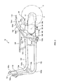
- Fig. 1 is a side view of a unit swing type motorcycle (motor scooter) 1 according to the embodiment of the invention.
- Fig. 2 is a side view of a body frame 10 included in the motorcycle 1.
- Fig. 3 is a plan view of the body frame 10.
- Fig. 4 is a side view of an engine unit 20.
- the engine unit 20 and a shock absorbing unit or buffer 50 as well as the body frame 10 are shown.
- the engine unit 20 is indicated by an alternate long and two short dashes line.
- the motorcycle 1 includes a front wheel 2, a rear wheel 3, a pivot shaft 109, and the shock absorbing unit 50 as well as the engine unit 20.
- the front wheel 2 is disposed in the front region of the motorcycle 1, and its axle 2a is supported by the lower end of a front fork 7 diagonally extending in the up-down direction.
- the upper part of the front fork 7 is rotatably supported by a head pipe 101 of the body frame 10.
- a handle 8 is connected with the upper end of the front fork 7.
- the rear wheel 3 is disposed in the rear region of the motorcycle 1.
- An axle 4 of the rear wheel 3 is rotatably supported by the rear part of the engine unit 20.
- the rear wheel 3 can swing with the engine unit 20 in the up-down direction relative to the body frame 10.
- the body frame 10 includes a pair of a right frame 10R and a left frame 10L as well as the head pipe 101.
- Each of the right frame 10R and the left frame 10L has an upper frame portion 102, a lower frame portion 103, a rear frame portion 104, a seat stay 105, a pivot support member 108, and a support plate member 118.
- the body frame 10 also includes a front cross portion 111, a shock absorbing unit support portion 112, and a rear cross portion 113 provided between the right frame 10R and the left frame 10L.
- a front end (upper end) 103a of the lower frame portion 103 is connected with the lower part of the head pipe 101.
- Each of the left and right lower frame portions 103, 103 extends downward and then bends toward the rear at a bend portion 103b while expanding to the side from the front end portion 103a (see Fig. 3 ) .
- a rear end 103c of the lower frame 103 bends upward and connects with the rear frame portion 104.
- the shock absorbing unit support portion 112 extends between the rear ends 103c of the left and right lower frames 103.
- the shock absorbing unit support portion 112 extends in the vehicle width direction, and shock absorbing unit attachment members 119 contact with the central portion of the shock absorbing unit support portion 112.
- the shock absorbing unit support portion 112 is a component having a substantially C-shaped horizontal cross section.
- the shock absorbing unit attachment members 119 are a pair of plate-shaped components, and are connected with the inside surface of the shock absorbing unit support portion 112 in such a condition as to project diagonally downward (see Fig. 4 ) .
- the rear frame portion 104 has a vertical frame portion 104a, an inclined frame portion 104b, and a rearward extending portion 104c.
- the vertical frame portion 104a extends upward from the rear end 103c of the lower frame portion 103, and an upper end 104d of the vertical frame portion 104a diagonally bends toward the rear of the vehicle body.
- the inclined frame portion 104b connects with the upper end 104d, and diagonally extends toward the rear of the vehicle body.
- An upper end 104e of the inclined frame portion 104b bends toward the rear, and the rearward extending portion 104c connects with the upper end 104e.
- the rear cross portion 113 extends between the left and right rearward extending portions 104c, 104c (see Fig. 3 ) .
- a front end (upper end) 102a of the upper frame portion 102 connects with the upper part of the head pipe 101.
- the upper frame portion 102 extends downward and bends toward the rear at a bend portion 102b while expanding toward the side from the front end 102a above the lower frame portion 103 (see Fig. 3 ).
- the upper frame portion 102 extends toward the rear from the bend portion 102b, and a rear end 102c of the upper frame portion 102 connects with the upper end 104d of the vertical frame portion 104a in the vertical direction.
- the front cross portion 111 extends between the front parts of the left and right upper frames 102 (see Fig. 3 ).
- the seat stay 105 extends in the front-rear direction of the vehicle body, and a rear end 105a of the seat stay 105 connects with an intermediate portion of the inclined frame portion 104b.
- a seat 9 is disposed above the seat stay 105 to be supported by the seat stay 105.
- a storage case 11 ( Fig. 1 ) is disposed below the seat 9. The storage case 11 is positioned between the left and right seat stays 105 and the upper frame portion 102.
- a support member 107 diagonally extending in the up-down direction is provided between the front part of the seat stay 105 and the upper frame portion 102.
- the support plate member 118 connects with the vertical frame portion 104a and the inclined frame portion 104b in such a manner as to extend from the intermediate portion of the inclined frame 104b to the lower end of the vertical frame 104a.
- the support plate member 118 extends toward the rear of the vehicle body from the vertical frame portion 104a and the inclined frame portion 104b.
- the lower part of the support plate member 118 supports the pivot support member 108.
- the pivot support member 108 is a cylindrical component, and the lower part of the support plate member 118 contacts the outer circumferential surface of the pivot support member 108.
- the left and right pivot support members 108, 108 support the pivot shaft 109 extending in the vehicle width direction.
- a reinforcement plate 115 connects the front end 102a of the upper frame portion 102 and the front end 103a of the lower frame portion 103.
- Two support members 116a and 116b extend between the bend portion 103b of the lower frame portion 103 and the bend portion 102b of the upper frame portion 102.
- the engine unit 20 has an engine 30, a transmission mechanism 40 for transmitting driving force outputted from the engine 30 to the rear wheel 3, and a rear arm 21.
- the engine unit 20 further has a pair of left and right supported members 22, 22 to be attached to the pivot shaft 109, and a shock absorbing unit attachment member 23 to which the shock absorbing unit 50 is attached.
- the motorcycle 1 is a unit swing type vehicle.
- the axle 4 of the rear wheel 3 is supported on the rear part of the engine unit 20 which can swing upward and downward with the rear wheel 3 with the fulcrum located at the pivot shaft 109.
- the engine 30 includes a cylinder block 30a containing a cylinder 31, a cylinder head 30b covering the upper part of the cylinder block 30a, a crank mechanism 32, a balancer mechanism 36, and a crank case 30c.
- the crank mechanism 32 has a piston 33, a crank shaft 34, and a connecting rod 35 connecting the crank shaft 34 and the piston 33.
- the cylinder block 30a and the cylinder head 30b are positioned such that the axial direction of the cylinder 31 (direction indicated by an arrow C in Fig. 4 ) extends in the up-down direction of the vehicle body.
- the storage case 11 is disposed forward of the cylinder block 30a and the cylinder head 30b.
- the cylinder 31 is slightly inclined toward the rear of the vehicle body.
- the crank case 30c is disposed forward of the engine unit 20, and accommodates the crank shaft 34 extending in the vehicle width direction (see Fig. 3 ).
- the piston 33 reciprocates within the cylinder 31 by the combustion of fuel supplied from an injector (not shown).
- the crank mechanism 32 converts the reciprocating movement of the piston 33 into rotational movement of the crank shaft 34.
- the transmission mechanism 40 reduces the rotation speed of the crank shaft and transmits the resultant rotation to the axle 4 of the rear wheel 3.
- the transmission mechanism 40 includes a continuously variable transmission 41, a driven shaft 45, and an intermediate shaft 46, and these components are accommodated in a transmission case 47 disposed on the left side of the rear wheel 3.
- a front part 47a of the transmission case 47 is attached to the side of the crank case 30c (see Fig. 3 ), and the transmission case 47 extends toward the rear of the vehicle body from the front part 47a.
- the continuously variable transmission 41 includes a driving pulley 42, a driven pulley 43, and a V-belt 44 wound around the driving pulley 42 and the driven pulley 43.
- the driving pulley 42 is accommodated in the front part 47a of the transmission case 47.
- the driving pulley 42 is attached to an end of the crank shaft 34 and rotates with the crank shaft 34.
- the driven shaft 45 is disposed behind the transmission case 47 at a position away from the axle 4 of the rear wheel 3.
- the driven pulley 43 engages with the driven shaft 45 in an idling condition for the driven shaft 45.
- the rotation force of the crank shaft 34 is transmitted to the driven pulley 43 via the driving pulley 42 and the V-belt 44.
- the radii of the portion of the V-belt 44 wound around the driving pulley 42 and the driven pulley 43 vary according to the revolutions of the crank shaft 34, thereby continuously varying the speed reduction ratio.
- the transmission mechanism 40 has a centrifugal clutch (not shown) coaxially with the driven shaft 45.
- the rotation force transmitted to the driven pulley 43 is further transmitted to the driven shaft 45 via the centrifugal clutch under the condition connected with the driven shaft 45.
- a gear 45a engages with the driven shaft 45 in such a manner as to interlock with the driven shaft 45.
- the rotation force transmitted to the drive shaft 45 is further transmitted to the intermediate shaft 46 via a large-diameter gear 46a provided to engage with the gear 45a and interlock with the intermediate shaft 46.
- the large-diameter gear 46a and a small-diameter gear 46b having a diameter smaller than that of the large-diameter gear 46a engage with the intermediate shaft 46.
- the rotation force transmitted to the intermediate shaft 46 is further transmitted to the axle 4 via the small-diameter gear 46b and a gear 4a engaging with the small-diameter gear 46b and interlocking with the axle 4.
- the rear arm 21 is a substantially triangular component disposed on the right side of the rear wheel 3, and the front part of the rear arm 21 is attached to the crank case 30c.
- the rear arm 21 extends toward the rear from its attachment position to the crank case 30c, and the axle 4 is supported by the rear end of the rear arm 21.
- the supported members 22, 22 are disposed at the front end of the engine unit 20, forward of the crankshaft 34.
- the supported members 22, 22 are so constructed as to project toward the front from a front wall 30d of the crank case 30c (see Fig. 4 ).
- the engine unit 20 extends from the supported members 22, 22 toward the rear, and the rear part of the transmission case 47 and the rear end of the rear arm 21 support the axle 4 of the rear wheel 3 such that the axle 4 can rotate.
- Fig. 5 illustrates the pivot support members 108, 108 and the support plate members 118 as viewed from the rear.
- An insertion hole 22a extending in the vehicle width direction is formed on each of the supported members 22, and the pivot shaft 109 is inserted into the insertion holes 22a.
- a virtual plane P containing the axle 4 and the pivot shaft 109 to which the supported members 22 are attached is substantially parallel with the road surface.
- the height of the supported members 22 is determined such that the supported members 22 can swing upward and downward from a horizontal plane (plane in parallel with road surface) containing the axle 4 at the time of running of the vehicle.
- an insertion hole extending in the vehicle width direction is formed on each of the pivot support members 108, and the pivot shaft 109 is inserted into these insertion holes.
- a cylindrical bushing 108a having an inside diameter corresponding to the outside diameter of the pivot shaft 109 is provided inside each of the insertion holes. The pivot shaft 109 is inserted into the interiors of the bushings 108a, and the pivot support members 108 support the pivot shaft 109 via the bushings 108a.
- the shock absorbing unit attachment member 23 is provided rearward of the shock absorbing unit attachment members 119 of the body frame 10 in such a manner as to project downward from a lower wall 30e of the crank case 30c.
- the rear end of the shock absorbing unit 50 is attached to the shock absorbing unit attachment member 23.
- the engine 30 has the balancer mechanism 36.
- the balancer mechanism 36 is a mechanism for reducing vibrations of the engine unit 20 caused by the reciprocating movement of the piston 33.
- the balancer mechanism 36 has a balancer shaft 37, a gear 37c rotating with the balancer shaft 37, and a balancer weight 37w rotating with the balancer shaft 37.
- the gear 37c engages with a gear (not shown) rotating with the crank shaft 34, and the balancer shaft 37 rotates in the direction opposite to the rotation of the crank shaft 34 at a speed equivalent to the rotational speed of the crank shaft 34.
- the position of the balancer shaft 37 and the position of the balancer weight 37w in the circumferential direction of the balancer shaft 37 are determined such that the vibration of the engine unit 20 is not transmitted from the supported members 22 to the pivot shaft 109 by reducing the vibration of the supported members 22.
- the details of the balancer mechanism 36 will be described later.
- the shock absorbing unit 50 expands and contracts in accordance with road surface variations to reduce rapid swing of the engine unit 20 and the rear wheel 3. As illustrated in Fig. 4 , the shock absorbing unit 50 extends between the shock absorbing unit attachment members 119 of the body frame 10 and the shock absorbing unit attachment member 23 formed on the crank case 30c.
- the shock absorbing unit 50 has a dumper 52, an engine side attachment member 55, and a frame side attachment member 56.
- the dumper 52 has a case 53 and a rod 54.
- a cylinder 53a is provided inside the case 53, and oil or gas is sealed into the cylinder 53a.
- a piston 53b is attached to the front end of the rod 54.
- the piston 53b is accommodated in the cylinder 53a.
- the rod 54 pulls or pushes the piston 53b according to the swing of the engine unit 20.
- a coil spring 51 is provided inside the cylinder 53a. The coil spring 51 pushes or biases the piston 53b so as to contract (shorten) the dumper 52.
- the engine side attachment member 55 extends toward the rear from the dumper 52.
- the rear end of the engine side attachment member 55 is attached to the shock absorbing unit attachment member 23 of the engine unit 20 by a bolt 27 in such a manner as to be rotatable relative to the shock absorbing unit attachment member 23.
- the frame side attachment member 56 extends toward the front from the damper 52, and the front end of the frame side attachment member 56 is attached to the shock absorbing unit attachment member 119 of the body frame 10 by a bolt 28.
- the shock absorbing unit 50 is provided below the pivot shaft 109 in a direction substantially parallel with the road surface.
- the frame side attachment member 56 is positioned forward of the pivot shaft 109, and the engine side attachment member 55 is positioned rearward of the pivot shaft 109.
- the expanding and contracting direction of the shock absorbing unit 50 (direction indicated by an arrow S in Fig. 4 ) extends in the circumferential or tangential direction of a circle defined around the pivot shaft 109. That is, the direction S is substantially perpendicular to a line T passing the center of the pivot shaft 109 and extending in its radial direction.
- Figs. 6 and 7 show the positional relationship between the crank mechanism 32 and the balancer mechanism 36.
- the balancer mechanism 36 has the balancer shaft 37 and the balancer weight 37w.
- the crank mechanism 32 has the piston 33, the crank shaft 34 and the connecting rod 35.
- the crank shaft 34 has a counter weight 34w1 provided on the side opposite to a crank pin 34p with the crank shaft 34 interposed therebetween and rotatable with the crank shaft 34.
- a weight 34w2 is disposed at a position different from the position of the counter weight 34w1 in the circumferential direction of the crank shaft 34 and is rotatable with the crank shaft 34.
- the counter weight 34w1 and the weight 34w2 are black circular marks for simplifying the present description.
- the balancer weight 37w is a black circular mark in Fig. 7 .
- the counter weight 34w1, the weight 34w2, and the crank pin 34p are disposed at equal distances from an axial center Co of the crank shaft 34 (at a distance r in Fig. 6 ) for simplifying the explanation.
- the position of the balancer shaft 37, the position of the balancer weight 37w in the circumferential direction of the balancer shaft 37, the position of the crank shaft 34, and the position of the weight 34w2 in the circumferential direction of the crank shaft 34 are determined such that vibration to be transmitted to the pivot shaft 109 via the supported members 22 can be reduced.
- inertia force generated by the reciprocating movements of the piston 33 and the small-end side (piston 33 side) of the connecting rod 35 within the cylinder 31 acts on the crank mechanism 32 in an axial direction Y of the cylinder 31.
- a primary inertia force f2 of this inertia force varies in accordance with the phase of the crank shaft 34.
- a resultant force hereinafter referred to as inertia force F1
- the direction of the inertia force F1 rotates with the rotation of the crank shaft 34.
- the locus produced by the vector of the inertia force F1 is indicated by an ellipse S2.
- the mass of the counter weight 34w1 is equivalent to the mass of the rotating portions such as the crank pin 34p and the large-end side of the connecting rod 35.
- the weight 34w2 and the counter weight 34w1 for controlling the direction of the ellipse S2 are separate components in this embodiment, these components may be formed integrally with each other.
- the balancer shaft 37 is positioned such that a line L2 connecting an axial center Bo of the balancer shaft 37 and the axial center Co of the crank shaft 34 extends in parallel with the line L1 discussed above.
- the balancer weight 37w rotating with the balancer shaft 37 is provided on the balancer shaft 37.
- centrifugal force F2 generated by the rotations of the balancer shaft 37 and the balancer weight 37w acts on the balancer mechanism 36.
- the locus produced by the vector of the centrifugal force F2 is indicated by a circle S3.
- the balancer weight 37w is provided in such a manner as to rotate around the axial center Bo of the balancer shaft 37 in the same direction as that of the inertia force F1.
- the position of the balancer weight 37w in the circumferential direction of the balancer shaft 37 is determined such that the direction of the centrifugal force F2 is the direction opposite to the direction of the inertia force F1 corresponding to the direction of the major axis and the minor axis of the ellipse S2 discussed above.
- the balancer shaft 37 is disposed away from the crank shaft 34.
- a moment of the centrifugal force F2 and the inertia force F1 act on the engine unit 20.
- the engine unit 20 vibrates by this moment, and acceleration is given to the pivot shaft 109.
- acceleration generated by the resultant force of the centrifugal force F2 and the inertia force F1 is given to the pivot shaft 109.
- the mass of the balancer weight 37w and the positional relationship between the balancer shaft 37 and the crank shaft 34 are determined such that the acceleration generated by the resultant force can be reduced by the acceleration generated by the moment of the centrifugal force F2 and the inertia force F1. More specifically, the mass of the balancer weight 37w is established such that the centrifugal force F2 of the balancer mechanism 36 becomes equivalent to the maximum of the inertia force F1 of the crank mechanism 32.
- the radius of the circle S3 is equivalent to the major axis of the ellipse S2 in Fig. 7 .
- the positional relationship between the crank shaft 34 and the balancer shaft 37 is specifically determined in the following manner. As illustrated in Fig. 7 , it is assumed that a distance from the line L1 connecting the center of gravity G of the engine unit 20 and an axial center Po of the pivot shaft 109 to the line L2 connecting the axial center Co of the crank shaft 34 and the axial center Bo of the balancer shaft 37 is L. It is also assumed that a distance from the center of gravity G of the engine unit 20 to the axial center Po of the pivot shaft 109 is Lp.
- M is the mass of the engine unit 20
- I is the moment of inertia of the engine unit 20 with respect to a line passing the center of gravity G and extending in parallel with the vehicle width direction.
- the value A is expressed by the following equation (3) using the angle ⁇ formed by the major axis direction X of the ellipse S2 discussed above and the axial direction S of the cylinder 31, the angle ⁇ formed by the weight 34w2 and the crank pin 34p, and the mass ratio k, as shown in Kikai Sekkei, volume 8, No. 9, pp. 43-44, published by Nikkan Kogyo Shinbun , for example.
- A k ⁇ sin ⁇ - ⁇ / sin ⁇
- a component F2v in a direction VD and a component F2p in a direction PD (direction in parallel with line L2) contained in the centrifugal force F2 of the balancer mechanism 36, and a component F1v in the direction VD and a component F1p in the direction PD contained in the inertia force F1 of the crank mechanism 32 are calculated.
- the radius of the major axis of the ellipse S2 (maximum of inertia force F1 of crank mechanism 32) is A ⁇ F as shown in Kikai Sekkei, volume 8, No. 9, pp. 43-44, published by Nikkan Kogyo Shinbun , for example.
- the radius of the minor axis (minimum of inertia force F1) is (1-A) ⁇ F.
- the angle of the centrifugal force F2 of the balancer mechanism 36 is ⁇ + ⁇ .
- the component F1v in the direction VD contained in the inertia force F1 of the crank shaft 34 is (1-A) ⁇ Fsin ⁇ .
- the component F1p in the direction PD contained in the inertia force F1 of the crank shaft 34 is AxFcos ⁇ .
- the mass of the balancer weight 37w is established such that the centrifugal force F2 of the balancer mechanism 36 is equivalent to the maximum of the inertia force F1 of the crank mechanism 32.
- the component F2v in the direction VD contained in the centrifugal force F2 of the balancer mechanism 36 is A ⁇ Fsin( ⁇ + ⁇ )
- the component F2p in the direction PD is A ⁇ Fcos( ⁇ + ⁇ ).
- the acceleration at the axial center Po in the direction PD is zero. That is, since the lines L1 and L2 are parallel with each other, an acceleration a3 at the axial center Po in the direction PD generated by the moment N is zero.
- the supported members 22 supported by the pivot shaft 109 project toward the front from the front wall 30d of the crank case 30c and is disposed at the front end portion of the engine unit 20.
- the distance from the pivot shaft 109 to the axle 4 of the rear wheel 3 increases.
- fluctuation in the wheelbase is reduced, and the running stability of the motorcycle is enhanced.
- an engine unit is supported by a body frame via a vibration-preventing suspension member which prevents transmission of vibration generated by the engine unit to the body frame.
- the suspension member needs to be extended toward the rear when the engine unit is disposed at a backward position with respect to the body frame to increase the wheelbase without changing the size of the body frame or the like, and this structure is complicated.
- the supported members 22 of the engine unit 20 are attached to the pivot shaft 109 without interposing such a suspension member therebetween.
- the position of the engine unit 20 with respect to the body frame 10 can be easily controlled and the wheelbase can be appropriately determined by increasing the projection of the supported members 22 toward the front, for example.
- the engine unit When the engine unit is supported by the body frame via the vibration-preventing suspension member, the engine unit does not necessarily move with the body frame as one body. In this case, the rider feels that acceleration of the vehicle starts with delay from the increase in the rotation speed of the rear wheel, and thus cannot sometimes obtain preferable operational feedback. According to the motorcycle 1, however, the engine unit 20 is attached to the pivot shaft 109 without interposing the suspension member therebetween. Thus, the rider can feel the start of acceleration of the vehicle without delay from the increase in the rotation speed of the rear wheel 3, which improves operational feedback of the rider.
- the cylinder block 30a and the cylinder head 30b are positioned such that the axial direction of the cylinder 31 extends in the up-down direction, and the shock absorbing unit 50 is disposed below the engine unit 20.
- This structure allows effective use of the space below the seat 9.
- the storage case 11 can be provided below the seat 9 as discussed above.
- the engine 30 has the balancer mechanism 36. Thus, vibration generated by reciprocating movement of the piston 33 within the cylinder 31 in the up-down direction is not transmitted to the body frame 10 via the supported members 22 and the pivot shaft 109.
- the invention is not limited to the example of the motorcycle 1 described above, but may be practiced otherwise with various modifications.
- the motorcycle 1 described in the example shown has an engine 30 driven by combustion of fuel as a power source of the vehicle.
- the power source is not limited to such an engine and may be a hybrid engine which combines an electric motor driven by supply of electric power and an engine.
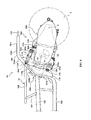
- Fig. 8 is a side view illustrating a body frame 10A and an engine unit 20A included in a motorcycle 1A in this example.
- the same reference numbers are given to the same parts included in the motorcycle 1, and for brevity a further explanation of these parts is not provided.
- the motorcycle 1A includes a shock absorbing unit 50A as well as the engine unit 20A.
- the engine unit 20A has an engine 30A, a transmission mechanism 40A, and a rear arm 21A.
- the engine 30A has a cylinder block 300a, a cylinder head 300b, and a crank case 300c.
- the cylinder block 300a contains the cylinder 31.
- the cylinder block 300a is inclined toward the front such that the axial direction of the cylinder 31 extends substantially in the front-rear direction of the vehicle.
- the cylinder 31 contains the piston 33.
- the crank case 300c is disposed rearward of the cylinder block 300a.
- the crank case 300c has supported members 22A projecting toward the front from the lower wall of the crank case 300c. Each end of the supported members 22A is positioned below the cylinder block 300a, and attached to the pivot shaft 109 supported by the pivot support member 108.
- the crank case 300c contains the crank shaft 34 extending in the vehicle width direction. Similarly to the above example, the supported members 22A are disposed forward of the crank shaft 34 in the motorcycle 1A.
- a shock absorbing member 23A is provided at the upper end of the front part of the rear arm 21A.
- An engine side attachment member 55A provided on the shock absorbing unit 50A is attached to the shock absorbing attachment member 23A such that the engine side attachment member 55A can rotate relative to the shock absorbing unit attachment member 23A.
- the shock absorbing unit 50A is disposed above the cylinder block 300a and the crank case 300c.
- the shock absorbing unit 50A is disposed such that its expanding and contracting direction (direction indicated by S in the figure) extends substantially in the front-rear direction of the vehicle and in the circumferential direction of the pivot shaft 109. That is, an expanding direction S of the shock absorbing unit 50A is perpendicular to a line T passing the axial center of the pivot shaft 109 and extending in the radial direction.
- a shock absorbing unit support member 112A extends between the left and right inclined frame portions 104b, and a pair of plate-shaped shock absorbing unit attachment members 119A contact the shock absorbing unit support member 112A.
- a frame side attachment member 56A of the shock absorbing unit 50A is attached to the shock absorbing unit attachment members 119A.
- the frame side attachment member 56A is positioned forward of the pivot shaft 109 with respect to the vehicle body, and the engine side attachment member 55A is positioned forward of the pivot shaft 109 with respect to the vehicle body.
- the shock absorbing unit 50A has a coil spring 51A which generates force in the direction for expanding the distance between the frame side attachment member 56A and the engine side attachment member 55A.
- the supported members 22A are positioned forward of the crank shaft 34 in the motorcycle 1A.
- This structure allows the distance between the pivot shaft 109 and the axle 4 of the rear wheel 3 to be enlarged compared with the structure where a central area and its vicinity near the center of gravity of the engine unit 20A are suspended by the body frame 10.
- the cylinder block 300a and the cylinder head 300c are disposed such that the axial direction of the cylinder 31 extends in the front-rear direction of the vehicle body, the space above the engine unit 20A can be effectively utilized.
Landscapes
- Engineering & Computer Science (AREA)
- Mechanical Engineering (AREA)
- Chemical & Material Sciences (AREA)
- Combustion & Propulsion (AREA)
- Transportation (AREA)
- Axle Suspensions And Sidecars For Cycles (AREA)
- Automatic Cycles, And Cycles In General (AREA)
- Arrangement Or Mounting Of Propulsion Units For Vehicles (AREA)
Abstract
Description
- The present invention relates to a technology for supporting an engine unit by a body frame in a unit swing system straddle-type vehicle.
- According to a unit swing system straddle-type vehicle (such as a motor scooter), an axle of a rear wheel is supported by the rear end of an engine unit which contains a transmission and an engine, and the engine unit is so constructed as to swing with the rear wheel with the fulcrum located at a pivot shaft suspended by the body frame. Such an arrangement is disclosed in, for example,
JP-A-2003-312578 - According to the straddle-type vehicle shown in
JP-A-2003-312578 - The invention has been developed to solve these problems. It is an object of the invention to provide a vehicle capable of obtaining preferable running stability by reducing fluctuations in wheelbase.
- In order to achieve the above object, a straddle-type vehicle according to the invention includes: a body frame; a pivot shaft supported by the body frame; a rear wheel disposed in the rear part of a vehicle body; and an engine unit which contains an engine having a crank shaft and a transmission mechanism for transmitting rotational force of the crank shaft to the rear wheel, and is capable of swinging upward and downward with the rear wheel with the fulcrum located at the pivot shaft. The crank shaft is disposed in the front part of the engine unit. The engine unit has a supported member disposed before the crank shaft and attached to the pivot shaft, and extends toward the rear from the supported member. An axle of the rear wheel is supported by the rear part of the engine unit.
- According to the straddle-type vehicle of the invention, the supported member attached to the pivot shaft is disposed before the crank shaft, the distance between the pivot shaft and the axle is larger than that in the structure where the central portion and its vicinity of the engine unit are attached to the pivot shaft. Thus, fluctuation in wheelbase can be reduced, and running stability can be enhanced. The straddle-type vehicle herein is a vehicle such as a motorcycle (including scooter), a four-wheel buggy, and a snow mobile.
- According to an example of the invention, the supported member is positioned at the front end of the engine unit. In this case, fluctuation in wheelbase can be further reduced, and running stability can be improved.
- In another example of the invention, the supported member attached to the pivot shaft is disposed at a level sufficient for swinging upward and downward from a horizontal surface containing the axle at the time of running of the vehicle. In this case, driving force generated by the rotation of the rear wheel can be transmitted from the supported member to the body frame via the pivot shaft more easily than in the structure where the supported member is disposed considerably away from the axle of the rear wheel in the up-down direction.
- In a further aspect of the invention, a shock absorbing unit which reduces vibration of the engine unit is further provided to the straddle-type vehicle. In addition, the shock absorbing unit is disposed in such a position as to expand and contract in the circumferential direction of a circle defined around the pivot shaft. In this case, force in directions other than the expanding and contracting direction of the shock absorbing unit does not easily act on the shock absorbing unit. Thus, the durability of the shock absorbing unit can be increased.
- In one aspect of the invention there is provided a vehicle, comprising:
- a body frame;
- a pivot shaft supported by the body frame; and
- an engine unit coupled to a rear wheel and capable of swinging upward and downward about the pivot shaft,
- It should be understood that the forward position of the support member is with reference to a front-rear direction of the vehicle.
- The rear wheel is preferably disposed in a rear part of the vehicle body.
- The rear wheel may be coupled to the engine unit via a transmission assembly adapted to transmit rotational force of the crank shaft to the rear wheel.
- The supported member may be positioned at the front end of the engine unit.
- The supported member attached to the pivot shaft may be disposed at a level sufficient for swinging upward and downward from a horizontal plane containing the axle at the time of running of the vehicle.
- The vehicle may further comprise a shock absorbing unit adapted to reduce vibration of the engine unit, wherein the shock absorbing unit may be disposed in such a position as to expand and contract in the circumferential direction of a circle defined around the pivot shaft.
- The vehicle may be provided in the form of a straddle-type vehicle
- These and other aspects of the present invention will now be described, by way of example only, with reference to the accompanying drawings, in which:
-
Fig. 1 is a side view of a motorcycle according to an embodiment of the invention; -
Fig. 2 is a side view of a body frame included in the motorcycle; -
Fig. 3 is a plan view of the body frame; -
Fig. 4 is a side view of an engine unit included in the motorcycle; -
Fig. 5 illustrates a pivot support member and a support plate member of the body frame as viewed from the rear; -
Fig. 6 is a view explaining a crank mechanism contained in the engine unit; -
Fig. 7 is a view explaining a positional relationship between the crank mechanism and a balancer mechanism; and -
Fig. 8 is a side view of a body frame and an engine unit included in a motorcycle according to another example of the invention. - An embodiment according to the invention is hereinafter described with reference to the drawings.
Fig. 1 is a side view of a unit swing type motorcycle (motor scooter) 1 according to the embodiment of the invention.Fig. 2 is a side view of abody frame 10 included in themotorcycle 1.Fig. 3 is a plan view of thebody frame 10.Fig. 4 is a side view of anengine unit 20. InFig. 2 , theengine unit 20 and a shock absorbing unit orbuffer 50 as well as thebody frame 10 are shown. InFig. 3 , theengine unit 20 is indicated by an alternate long and two short dashes line. - As illustrated in
Fig. 1 , themotorcycle 1 includes afront wheel 2, arear wheel 3, apivot shaft 109, and theshock absorbing unit 50 as well as theengine unit 20. Thefront wheel 2 is disposed in the front region of themotorcycle 1, and itsaxle 2a is supported by the lower end of a front fork 7 diagonally extending in the up-down direction. The upper part of the front fork 7 is rotatably supported by ahead pipe 101 of thebody frame 10. A handle 8 is connected with the upper end of the front fork 7. Therear wheel 3 is disposed in the rear region of themotorcycle 1. An axle 4 of therear wheel 3 is rotatably supported by the rear part of theengine unit 20. Therear wheel 3 can swing with theengine unit 20 in the up-down direction relative to thebody frame 10. - As illustrated in
Fig. 2 or3 , thebody frame 10 includes a pair of aright frame 10R and aleft frame 10L as well as thehead pipe 101. Each of theright frame 10R and theleft frame 10L has anupper frame portion 102, alower frame portion 103, arear frame portion 104, aseat stay 105, apivot support member 108, and asupport plate member 118. Thebody frame 10 also includes afront cross portion 111, a shock absorbingunit support portion 112, and arear cross portion 113 provided between theright frame 10R and theleft frame 10L. - As illustrated in
Fig. 2 , a front end (upper end) 103a of thelower frame portion 103 is connected with the lower part of thehead pipe 101. Each of the left and rightlower frame portions bend portion 103b while expanding to the side from thefront end portion 103a (seeFig. 3 ) . Arear end 103c of thelower frame 103 bends upward and connects with therear frame portion 104. As illustrated inFig. 3 , the shock absorbingunit support portion 112 extends between therear ends 103c of the left and right lower frames 103. The shock absorbingunit support portion 112 extends in the vehicle width direction, and shock absorbingunit attachment members 119 contact with the central portion of the shock absorbingunit support portion 112. In this embodiment, the shock absorbingunit support portion 112 is a component having a substantially C-shaped horizontal cross section. The shock absorbingunit attachment members 119 are a pair of plate-shaped components, and are connected with the inside surface of the shock absorbingunit support portion 112 in such a condition as to project diagonally downward (seeFig. 4 ) . - As illustrated in
Fig. 2 , therear frame portion 104 has avertical frame portion 104a, aninclined frame portion 104b, and a rearward extendingportion 104c. Thevertical frame portion 104a extends upward from therear end 103c of thelower frame portion 103, and anupper end 104d of thevertical frame portion 104a diagonally bends toward the rear of the vehicle body. Theinclined frame portion 104b connects with theupper end 104d, and diagonally extends toward the rear of the vehicle body. Anupper end 104e of theinclined frame portion 104b bends toward the rear, and the rearward extendingportion 104c connects with theupper end 104e. Therear cross portion 113 extends between the left and right rearward extendingportions Fig. 3 ) . - A front end (upper end) 102a of the
upper frame portion 102 connects with the upper part of thehead pipe 101. Theupper frame portion 102 extends downward and bends toward the rear at abend portion 102b while expanding toward the side from thefront end 102a above the lower frame portion 103 (seeFig. 3 ). Theupper frame portion 102 extends toward the rear from thebend portion 102b, and arear end 102c of theupper frame portion 102 connects with theupper end 104d of thevertical frame portion 104a in the vertical direction. Thefront cross portion 111 extends between the front parts of the left and right upper frames 102 (seeFig. 3 ). - The
seat stay 105 extends in the front-rear direction of the vehicle body, and arear end 105a of theseat stay 105 connects with an intermediate portion of theinclined frame portion 104b. As illustrated inFig. 1 , aseat 9 is disposed above the seat stay 105 to be supported by theseat stay 105. A storage case 11 (Fig. 1 ) is disposed below theseat 9. Thestorage case 11 is positioned between the left and right seat stays 105 and theupper frame portion 102. As illustrated inFig. 2 , asupport member 107 diagonally extending in the up-down direction is provided between the front part of theseat stay 105 and theupper frame portion 102. - As illustrated in
Fig. 2 , thesupport plate member 118 connects with thevertical frame portion 104a and theinclined frame portion 104b in such a manner as to extend from the intermediate portion of theinclined frame 104b to the lower end of thevertical frame 104a. Thesupport plate member 118 extends toward the rear of the vehicle body from thevertical frame portion 104a and theinclined frame portion 104b. The lower part of thesupport plate member 118 supports thepivot support member 108. In this embodiment, thepivot support member 108 is a cylindrical component, and the lower part of thesupport plate member 118 contacts the outer circumferential surface of thepivot support member 108. The left and rightpivot support members pivot shaft 109 extending in the vehicle width direction. - A
reinforcement plate 115 connects thefront end 102a of theupper frame portion 102 and thefront end 103a of thelower frame portion 103. Twosupport members bend portion 103b of thelower frame portion 103 and thebend portion 102b of theupper frame portion 102. - As illustrated in
Figs. 3 and4 , theengine unit 20 has anengine 30, atransmission mechanism 40 for transmitting driving force outputted from theengine 30 to therear wheel 3, and arear arm 21. Theengine unit 20 further has a pair of left and right supportedmembers pivot shaft 109, and a shock absorbingunit attachment member 23 to which theshock absorbing unit 50 is attached. As mentioned above, themotorcycle 1 is a unit swing type vehicle. Thus, the axle 4 of therear wheel 3 is supported on the rear part of theengine unit 20 which can swing upward and downward with therear wheel 3 with the fulcrum located at thepivot shaft 109. - As illustrated in
Fig. 4 , theengine 30 includes acylinder block 30a containing acylinder 31, acylinder head 30b covering the upper part of thecylinder block 30a, acrank mechanism 32, abalancer mechanism 36, and a crankcase 30c. Thecrank mechanism 32 has apiston 33, acrank shaft 34, and a connectingrod 35 connecting thecrank shaft 34 and thepiston 33. - The
cylinder block 30a and thecylinder head 30b are positioned such that the axial direction of the cylinder 31 (direction indicated by an arrow C inFig. 4 ) extends in the up-down direction of the vehicle body. As illustrated inFig. 1 , thestorage case 11 is disposed forward of thecylinder block 30a and thecylinder head 30b. According to the example shown inFig. 4 , thecylinder 31 is slightly inclined toward the rear of the vehicle body. The crankcase 30c is disposed forward of theengine unit 20, and accommodates thecrank shaft 34 extending in the vehicle width direction (seeFig. 3 ). Thepiston 33 reciprocates within thecylinder 31 by the combustion of fuel supplied from an injector (not shown). Thecrank mechanism 32 converts the reciprocating movement of thepiston 33 into rotational movement of thecrank shaft 34. - The
transmission mechanism 40 reduces the rotation speed of the crank shaft and transmits the resultant rotation to the axle 4 of therear wheel 3. In this embodiment, thetransmission mechanism 40 includes a continuously variable transmission 41, a drivenshaft 45, and anintermediate shaft 46, and these components are accommodated in atransmission case 47 disposed on the left side of therear wheel 3. Afront part 47a of thetransmission case 47 is attached to the side of thecrank case 30c (seeFig. 3 ), and thetransmission case 47 extends toward the rear of the vehicle body from thefront part 47a. - The continuously variable transmission 41 includes a driving
pulley 42, a drivenpulley 43, and a V-belt 44 wound around the drivingpulley 42 and the drivenpulley 43. The drivingpulley 42 is accommodated in thefront part 47a of thetransmission case 47. The drivingpulley 42 is attached to an end of thecrank shaft 34 and rotates with thecrank shaft 34. The drivenshaft 45 is disposed behind thetransmission case 47 at a position away from the axle 4 of therear wheel 3. The drivenpulley 43 engages with the drivenshaft 45 in an idling condition for the drivenshaft 45. The rotation force of thecrank shaft 34 is transmitted to the drivenpulley 43 via the drivingpulley 42 and the V-belt 44. The radii of the portion of the V-belt 44 wound around the drivingpulley 42 and the drivenpulley 43 vary according to the revolutions of thecrank shaft 34, thereby continuously varying the speed reduction ratio. - The
transmission mechanism 40 has a centrifugal clutch (not shown) coaxially with the drivenshaft 45. The rotation force transmitted to the drivenpulley 43 is further transmitted to the drivenshaft 45 via the centrifugal clutch under the condition connected with the drivenshaft 45. Agear 45a engages with the drivenshaft 45 in such a manner as to interlock with the drivenshaft 45. The rotation force transmitted to thedrive shaft 45 is further transmitted to theintermediate shaft 46 via a large-diameter gear 46a provided to engage with thegear 45a and interlock with theintermediate shaft 46. The large-diameter gear 46a and a small-diameter gear 46b having a diameter smaller than that of the large-diameter gear 46a engage with theintermediate shaft 46. The rotation force transmitted to theintermediate shaft 46 is further transmitted to the axle 4 via the small-diameter gear 46b and agear 4a engaging with the small-diameter gear 46b and interlocking with the axle 4. - As illustrated in
Fig. 2 , therear arm 21 is a substantially triangular component disposed on the right side of therear wheel 3, and the front part of therear arm 21 is attached to the crankcase 30c. Therear arm 21 extends toward the rear from its attachment position to the crankcase 30c, and the axle 4 is supported by the rear end of therear arm 21. - As illustrated in
Fig. 3 or4 , the supportedmembers engine unit 20, forward of thecrankshaft 34. In this embodiment, the supportedmembers front wall 30d of thecrank case 30c (seeFig. 4 ). Theengine unit 20 extends from the supportedmembers transmission case 47 and the rear end of therear arm 21 support the axle 4 of therear wheel 3 such that the axle 4 can rotate.Fig. 5 illustrates thepivot support members support plate members 118 as viewed from the rear. Aninsertion hole 22a extending in the vehicle width direction is formed on each of the supportedmembers 22, and thepivot shaft 109 is inserted into theinsertion holes 22a. By this structure, the supportedmembers 22 rotate relative to thepivot shaft 109 in accordance with the variations in the road surface, allowing theengine unit 20 to swing with the fulcrum located at thepivot shaft 109. - As illustrated in
Fig. 1 , a virtual plane P containing the axle 4 and thepivot shaft 109 to which the supportedmembers 22 are attached is substantially parallel with the road surface. The height of the supportedmembers 22 is determined such that the supportedmembers 22 can swing upward and downward from a horizontal plane (plane in parallel with road surface) containing the axle 4 at the time of running of the vehicle. - As illustrated in
Fig. 5 , an insertion hole extending in the vehicle width direction is formed on each of thepivot support members 108, and thepivot shaft 109 is inserted into these insertion holes. Acylindrical bushing 108a having an inside diameter corresponding to the outside diameter of thepivot shaft 109 is provided inside each of the insertion holes. Thepivot shaft 109 is inserted into the interiors of thebushings 108a, and thepivot support members 108 support thepivot shaft 109 via thebushings 108a. - As illustrated in
Fig. 4 , the shock absorbingunit attachment member 23 is provided rearward of the shock absorbingunit attachment members 119 of thebody frame 10 in such a manner as to project downward from alower wall 30e of thecrank case 30c. The rear end of theshock absorbing unit 50 is attached to the shock absorbingunit attachment member 23. - As discussed above, the
engine 30 has thebalancer mechanism 36. Thebalancer mechanism 36 is a mechanism for reducing vibrations of theengine unit 20 caused by the reciprocating movement of thepiston 33. As illustrated inFig. 4 , thebalancer mechanism 36 has abalancer shaft 37, agear 37c rotating with thebalancer shaft 37, and abalancer weight 37w rotating with thebalancer shaft 37. Thegear 37c engages with a gear (not shown) rotating with thecrank shaft 34, and thebalancer shaft 37 rotates in the direction opposite to the rotation of thecrank shaft 34 at a speed equivalent to the rotational speed of thecrank shaft 34. In this embodiment, the position of thebalancer shaft 37 and the position of thebalancer weight 37w in the circumferential direction of thebalancer shaft 37 are determined such that the vibration of theengine unit 20 is not transmitted from the supportedmembers 22 to thepivot shaft 109 by reducing the vibration of the supportedmembers 22. The details of thebalancer mechanism 36 will be described later. - The
shock absorbing unit 50 expands and contracts in accordance with road surface variations to reduce rapid swing of theengine unit 20 and therear wheel 3. As illustrated inFig. 4 , theshock absorbing unit 50 extends between the shock absorbingunit attachment members 119 of thebody frame 10 and the shock absorbingunit attachment member 23 formed on thecrank case 30c. Theshock absorbing unit 50 has adumper 52, an engineside attachment member 55, and a frameside attachment member 56. Thedumper 52 has acase 53 and arod 54. - A
cylinder 53a is provided inside thecase 53, and oil or gas is sealed into thecylinder 53a. Apiston 53b is attached to the front end of therod 54. Thepiston 53b is accommodated in thecylinder 53a. Therod 54 pulls or pushes thepiston 53b according to the swing of theengine unit 20. In this embodiment, acoil spring 51 is provided inside thecylinder 53a. Thecoil spring 51 pushes or biases thepiston 53b so as to contract (shorten) thedumper 52. - The engine
side attachment member 55 extends toward the rear from thedumper 52. The rear end of the engineside attachment member 55 is attached to the shock absorbingunit attachment member 23 of theengine unit 20 by abolt 27 in such a manner as to be rotatable relative to the shock absorbingunit attachment member 23. - The frame
side attachment member 56 extends toward the front from thedamper 52, and the front end of the frameside attachment member 56 is attached to the shock absorbingunit attachment member 119 of thebody frame 10 by abolt 28. - The
shock absorbing unit 50 is provided below thepivot shaft 109 in a direction substantially parallel with the road surface. The frameside attachment member 56 is positioned forward of thepivot shaft 109, and the engineside attachment member 55 is positioned rearward of thepivot shaft 109. Thus, the expanding and contracting direction of the shock absorbing unit 50 (direction indicated by an arrow S inFig. 4 ) extends in the circumferential or tangential direction of a circle defined around thepivot shaft 109. That is, the direction S is substantially perpendicular to a line T passing the center of thepivot shaft 109 and extending in its radial direction. - The
crank mechanism 32 and thebalancer mechanism 36 contained in theengine 30 will now be explained.Figs. 6 and7 show the positional relationship between thecrank mechanism 32 and thebalancer mechanism 36. As discussed above, thebalancer mechanism 36 has thebalancer shaft 37 and thebalancer weight 37w. Thecrank mechanism 32 has thepiston 33, thecrank shaft 34 and the connectingrod 35. Thecrank shaft 34 has a counter weight 34w1 provided on the side opposite to a crankpin 34p with thecrank shaft 34 interposed therebetween and rotatable with thecrank shaft 34. Also, a weight 34w2 is disposed at a position different from the position of the counter weight 34w1 in the circumferential direction of thecrank shaft 34 and is rotatable with thecrank shaft 34. InFigs. 6 and7 , the counter weight 34w1 and the weight 34w2 are black circular marks for simplifying the present description. Similarly, thebalancer weight 37w is a black circular mark inFig. 7 . In this embodiment, it is assumed that the counter weight 34w1, the weight 34w2, and thecrank pin 34p are disposed at equal distances from an axial center Co of the crank shaft 34 (at a distance r inFig. 6 ) for simplifying the explanation. - In this embodiment, the position of the
balancer shaft 37, the position of thebalancer weight 37w in the circumferential direction of thebalancer shaft 37, the position of thecrank shaft 34, and the position of the weight 34w2 in the circumferential direction of thecrank shaft 34 are determined such that vibration to be transmitted to thepivot shaft 109 via the supportedmembers 22 can be reduced. - Initially, the position of the weight 34w2 in the circumferential direction of the
crank shaft 34 is explained. Centrifugal force generated by the rotations of the counter weight 34w1, the weight 34w2, thecrank pin 34p, and the large-end side of the connecting rod 35 (crankshaft 34 side) around the axial center Co of thecrank shaft 34 acts on thecrank mechanism 32. The centrifugal force produced by combining the centrifugal forces generated by these components is indicated by f1 inFig. 6 . The direction of the centrifugal force f1 rotates in accordance with the phase of thecrank shaft 34. InFig. 6 , the locus produced by the vector of the centrifugal force f1 is indicated by a circle S1. Also, inertia force generated by the reciprocating movements of thepiston 33 and the small-end side (piston 33 side) of the connectingrod 35 within thecylinder 31 acts on thecrank mechanism 32 in an axial direction Y of thecylinder 31. A primary inertia force f2 of this inertia force varies in accordance with the phase of thecrank shaft 34. Thus, a resultant force (hereinafter referred to as inertia force F1) of the primary inertia force f2 and the centrifugal force f1 acts on thecrank mechanism 32. The direction of the inertia force F1 rotates with the rotation of thecrank shaft 34. InFig. 6 , the locus produced by the vector of the inertia force F1 is indicated by an ellipse S2. - According to this embodiment, the mass of the counter weight 34w1 is equivalent to the mass of the rotating portions such as the
crank pin 34p and the large-end side of the connectingrod 35. In this case, the direction of the major axis of the ellipse S2 (direction indicated by an arrow X inFig. 6 ) is determined according to a ratio k of a mass Mp of the reciprocating portion such as thepiston 33 and the small-end of the connectingrod 35 to a mass Mc of the weight 34w2 (hereinafter referred to as mass ratio (k=Mc/Mp) and the position of the weight 34w2 in the circumferential direction of thecrank shaft 34. That is, assuming that an angle formed by the axial direction Y of thecylinder 31 and the direction X is χ and that an angle formed by the position of the weight 34w2 and the position of thecrank pin 34p is φ, the angle χ is expressed by the following equation as shown in Kikai Sekkei, volume 8, No. 9, pp. 43-44, published by Nikkan Kogyo Shinbun:
In this embodiment, the mass Mc of the weight 34w2 and the position of the weight 34w2 (angle φ inFig. 6 ) are determined such that the direction X of the major axis of the ellipse S2 extends in parallel with a straight line L1 connecting a center of gravity G of theengine unit 20 and an axial center Po of thepivot shaft 109. While the weight 34w2 and the counter weight 34w1 for controlling the direction of the ellipse S2 are separate components in this embodiment, these components may be formed integrally with each other. - Details of the
balancer mechanism 36 will now be described. As illustrated inFig. 7 , thebalancer shaft 37 is positioned such that a line L2 connecting an axial center Bo of thebalancer shaft 37 and the axial center Co of thecrank shaft 34 extends in parallel with the line L1 discussed above. As mentioned above, thebalancer weight 37w rotating with thebalancer shaft 37 is provided on thebalancer shaft 37. Thus, centrifugal force F2 generated by the rotations of thebalancer shaft 37 and thebalancer weight 37w acts on thebalancer mechanism 36. InFig. 7 , the locus produced by the vector of the centrifugal force F2 is indicated by a circle S3. Thebalancer weight 37w is provided in such a manner as to rotate around the axial center Bo of thebalancer shaft 37 in the same direction as that of the inertia force F1. The position of thebalancer weight 37w in the circumferential direction of thebalancer shaft 37 is determined such that the direction of the centrifugal force F2 is the direction opposite to the direction of the inertia force F1 corresponding to the direction of the major axis and the minor axis of the ellipse S2 discussed above. - The positional relationship between the
crank shaft 34 and thebalancer shaft 37, and the mass of thebalancer weight 37w will now be explained. - As illustrated in
Fig. 7 , thebalancer shaft 37 is disposed away from thecrank shaft 34. Thus, a moment of the centrifugal force F2 and the inertia force F1 act on theengine unit 20. Theengine unit 20 vibrates by this moment, and acceleration is given to thepivot shaft 109. Also, acceleration generated by the resultant force of the centrifugal force F2 and the inertia force F1 is given to thepivot shaft 109. - According to this example shown herein, the mass of the
balancer weight 37w and the positional relationship between thebalancer shaft 37 and thecrank shaft 34 are determined such that the acceleration generated by the resultant force can be reduced by the acceleration generated by the moment of the centrifugal force F2 and the inertia force F1. More specifically, the mass of thebalancer weight 37w is established such that the centrifugal force F2 of thebalancer mechanism 36 becomes equivalent to the maximum of the inertia force F1 of thecrank mechanism 32. Thus, the radius of the circle S3 is equivalent to the major axis of the ellipse S2 inFig. 7 . - The positional relationship between the
crank shaft 34 and thebalancer shaft 37 is specifically determined in the following manner. As illustrated inFig. 7 , it is assumed that a distance from the line L1 connecting the center of gravity G of theengine unit 20 and an axial center Po of thepivot shaft 109 to the line L2 connecting the axial center Co of thecrank shaft 34 and the axial center Bo of thebalancer shaft 37 is L. It is also assumed that a distance from the center of gravity G of theengine unit 20 to the axial center Po of thepivot shaft 109 is Lp. It is further assumed that a distance from a line L3 passing through the center of gravity G and extending in parallel with a direction VD (direction perpendicular to the lines L1 and L2) to the axial center Bo of thebalancer shaft 34. It is further assumed that a distance from the line L3 to the axial center Co of thecrank shaft 34 is Lc. In this case, the positions of thecrank shaft 34 and thebalancer shaft 37 are determined such that the respective distances discussed above satisfy the following equation (2):
In the equation (2), M is the mass of theengine unit 20, and I is the moment of inertia of theengine unit 20 with respect to a line passing the center of gravity G and extending in parallel with the vehicle width direction. The value A is a ratio of the major axis to the minor axis of the ellipse S2 produced by the vector of the inertia force F1 of the crank mechanism 32 (major axis: minor axis = A: (1-A)). The value A is expressed by the following equation (3) using the angle χ formed by the major axis direction X of the ellipse S2 discussed above and the axial direction S of thecylinder 31, the angle φ formed by the weight 34w2 and thecrank pin 34p, and the mass ratio k, as shown in Kikai Sekkei, volume 8, No. 9, pp. 43-44, published by Nikkan Kogyo Shinbun, for example.
- Details of equation (2) will now be explained.
- Initially, a component F2v in a direction VD and a component F2p in a direction PD (direction in parallel with line L2) contained in the centrifugal force F2 of the
balancer mechanism 36, and a component F1v in the direction VD and a component F1p in the direction PD contained in the inertia force F1 of thecrank mechanism 32 are calculated. - When the maximum of the primary inertial force acting on the reciprocating portion (mass m) in the
crank mechanism 32 such as thepiston 33 is F (F=mrω2, r=distance from axial center Co ofcrank shaft 34 to crankpin 34p, ω=angular speed of crank shaft 34), the radius of the major axis of the ellipse S2 (maximum of inertia force F1 of crank mechanism 32) is A×F as shown in Kikai Sekkei, volume 8, No. 9, pp. 43-44, published by Nikkan Kogyo Shinbun, for example. In this case, the radius of the minor axis (minimum of inertia force F1) is (1-A) ×F. As illustrated inFig. 7 , when the angle of the inertia force F1 of thecrank mechanism 32 to the line L2 is θ, the angle of the centrifugal force F2 of thebalancer mechanism 36 is π+θ. Thus, the component F1v in the direction VD contained in the inertia force F1 of thecrank shaft 34 is (1-A)×Fsinθ. The component F1p in the direction PD contained in the inertia force F1 of thecrank shaft 34 is AxFcosθ. The mass of thebalancer weight 37w is established such that the centrifugal force F2 of thebalancer mechanism 36 is equivalent to the maximum of the inertia force F1 of thecrank mechanism 32. Thus, the component F2v in the direction VD contained in the centrifugal force F2 of thebalancer mechanism 36 is A×Fsin(π+θ), and the component F2p in the direction PD is A×Fcos(π+θ). - Then, a component in the direction VD (a1 in
Fig. 7 ) contained in the acceleration of thepivot shaft 109 generated by the moment of the centrifugal force F2 and the inertia force F1 is calculated. A moment N of the inertia force F1 and the centrifugal force F2 around the center of gravity G is expressed by the following equation (4):
- Since cos(π+θ)=-cosθ and sin(π+θ)=-sinθ, the equation (4) can be expressed by the following equation (5):

- When the angular acceleration generated by the moment N around the center of gravity G is β and the acceleration at the axial center Po in the direction VD generated by the moment N is a1, the acceleration a1 in the direction VD and the angular acceleration β are expressed by the following equations (6) and (7):


where I is the moment of inertia of theengine unit 20 with respect to the line passing through the center of gravity G and extending in parallel with the vehicle width direction as discussed above. - Based on the equation (5), the equation (7) can be expressed by the following equation (8):

Based on the equations (6) and (8), the acceleration a1 can be expressed by the following equation (9):
- An acceleration a2 at the axial center Po in the direction VD generated by the resultant force of the inertia force F1 and the centrifugal force F2 is expressed by the following equation (10):

where M is the mass of theengine unit 20 as discussed above. - When the acceleration a1 at the axial center Po in the direction VD generated by the moment N and the acceleration a2 at the axial center Po in the direction VD generated by the resultant force of the inertia force F1 and the centrifugal force F2 cancel each other, that is, when a1+a2=0, the axial center Po of the
pivot shaft 109 becomes a momentary rotation center of theengine unit 20, thereby reducing vibration of thepivot shaft 109 in the direction VD. The sum of the acceleration a1 and the acceleration a2 is expressed by the following equation based on the equations (9) and (10):
This equation can be arranged in the following manner:
Since F≠0, the following equation can be obtained:
In this case, the following (11) holds when sinθ≠0 (θ≠0, in case of π):
By arranging the equation (11), the relationship between the ratio A of the major axis to the minor axis of the ellipse S2 produced by the vector of the inertia force F1 acting on thecrank mechanism 32 and the distances Lp, Lc and Lb can be expressed by the following equation equivalent to the equation (2) shown above:
- When sinθ=0 (θ=0, in case of π), each of the accelerators a1 and a2 is zero based on the equations (9) and (10). Thus, the equation a1+a2=0 is satisfied. This is the explanation of the equation (2) which determines the positional relationship between the
crank shaft 34, thebalancer shaft 37, and the center of gravity G. - The acceleration at the axial center Po in the direction PD is zero. That is, since the lines L1 and L2 are parallel with each other, an acceleration a3 at the axial center Po in the direction PD generated by the moment N is zero.
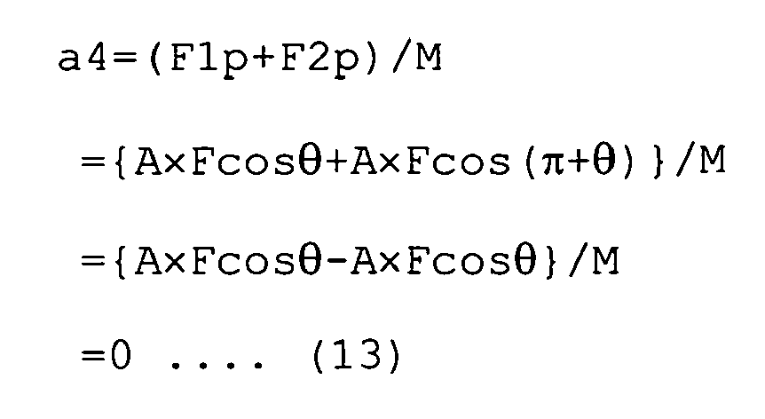
- An acceleration a4 at the axial center Po in the direction PD generated by the resultant force of the inertia force F1 and the centrifugal force F2 can be expressed by the following equation (13):
- As a result, the equation a3+a4=0 is satisfied. Since the acceleration at the axial center Po generated in the direction PD is zero, vibration at the axial center Po of the
pivot shaft 109 in the direction PD is reduced. - According to the
motorcycle 1 described above, the supportedmembers 22 supported by thepivot shaft 109 project toward the front from thefront wall 30d of thecrank case 30c and is disposed at the front end portion of theengine unit 20. In this case, the distance from thepivot shaft 109 to the axle 4 of therear wheel 3 increases. Thus, fluctuation in the wheelbase is reduced, and the running stability of the motorcycle is enhanced. - According to a typical unit swing type motorcycle, an engine unit is supported by a body frame via a vibration-preventing suspension member which prevents transmission of vibration generated by the engine unit to the body frame. In this structure, the suspension member needs to be extended toward the rear when the engine unit is disposed at a backward position with respect to the body frame to increase the wheelbase without changing the size of the body frame or the like, and this structure is complicated. According to the
motorcycle 1 described above, however, the supportedmembers 22 of theengine unit 20 are attached to thepivot shaft 109 without interposing such a suspension member therebetween. Thus, the position of theengine unit 20 with respect to thebody frame 10 can be easily controlled and the wheelbase can be appropriately determined by increasing the projection of the supportedmembers 22 toward the front, for example. When the engine unit is supported by the body frame via the vibration-preventing suspension member, the engine unit does not necessarily move with the body frame as one body. In this case, the rider feels that acceleration of the vehicle starts with delay from the increase in the rotation speed of the rear wheel, and thus cannot sometimes obtain preferable operational feedback. According to themotorcycle 1, however, theengine unit 20 is attached to thepivot shaft 109 without interposing the suspension member therebetween. Thus, the rider can feel the start of acceleration of the vehicle without delay from the increase in the rotation speed of therear wheel 3, which improves operational feedback of the rider. - Moreover, the
cylinder block 30a and thecylinder head 30b are positioned such that the axial direction of thecylinder 31 extends in the up-down direction, and theshock absorbing unit 50 is disposed below theengine unit 20. This structure allows effective use of the space below theseat 9. For example, thestorage case 11 can be provided below theseat 9 as discussed above. Furthermore, theengine 30 has thebalancer mechanism 36. Thus, vibration generated by reciprocating movement of thepiston 33 within thecylinder 31 in the up-down direction is not transmitted to thebody frame 10 via the supportedmembers 22 and thepivot shaft 109. - The invention is not limited to the example of the
motorcycle 1 described above, but may be practiced otherwise with various modifications. For example, themotorcycle 1 described in the example shown has anengine 30 driven by combustion of fuel as a power source of the vehicle. However, the power source is not limited to such an engine and may be a hybrid engine which combines an electric motor driven by supply of electric power and an engine. - While the
cylinder block 30a and thecylinder head 30b are disposed such that the axial direction of thecylinder 31 extends in the up-down direction in themotorcycle 1 described above, the cylinder block and the cylinder head may be positioned such that the axial direction of the cylinder extends in the front-rear direction of the vehicle body.Fig. 8 is a side view illustrating a body frame 10A and anengine unit 20A included in amotorcycle 1A in this example. In this figure, the same reference numbers are given to the same parts included in themotorcycle 1, and for brevity a further explanation of these parts is not provided. - As illustrated in the figure, the
motorcycle 1A includes ashock absorbing unit 50A as well as theengine unit 20A. Theengine unit 20A has anengine 30A, atransmission mechanism 40A, and arear arm 21A. Theengine 30A has acylinder block 300a, acylinder head 300b, and a crankcase 300c. Thecylinder block 300a contains thecylinder 31. Thecylinder block 300a is inclined toward the front such that the axial direction of thecylinder 31 extends substantially in the front-rear direction of the vehicle. Thecylinder 31 contains thepiston 33. - The crank
case 300c is disposed rearward of thecylinder block 300a. The crankcase 300c has supportedmembers 22A projecting toward the front from the lower wall of thecrank case 300c. Each end of the supportedmembers 22A is positioned below thecylinder block 300a, and attached to thepivot shaft 109 supported by thepivot support member 108. - The crank
case 300c contains thecrank shaft 34 extending in the vehicle width direction. Similarly to the above example, the supportedmembers 22A are disposed forward of thecrank shaft 34 in themotorcycle 1A. - A
shock absorbing member 23A is provided at the upper end of the front part of therear arm 21A. An engineside attachment member 55A provided on theshock absorbing unit 50A is attached to the shock absorbingattachment member 23A such that the engineside attachment member 55A can rotate relative to the shock absorbingunit attachment member 23A. Theshock absorbing unit 50A is disposed above thecylinder block 300a and the crankcase 300c. Theshock absorbing unit 50A is disposed such that its expanding and contracting direction (direction indicated by S in the figure) extends substantially in the front-rear direction of the vehicle and in the circumferential direction of thepivot shaft 109. That is, an expanding direction S of theshock absorbing unit 50A is perpendicular to a line T passing the axial center of thepivot shaft 109 and extending in the radial direction. - According to the
motorcycle 1A, a shock absorbingunit support member 112A extends between the left and rightinclined frame portions 104b, and a pair of plate-shaped shock absorbingunit attachment members 119A contact the shock absorbingunit support member 112A. A frameside attachment member 56A of theshock absorbing unit 50A is attached to the shock absorbingunit attachment members 119A. The frameside attachment member 56A is positioned forward of thepivot shaft 109 with respect to the vehicle body, and the engineside attachment member 55A is positioned forward of thepivot shaft 109 with respect to the vehicle body. Theshock absorbing unit 50A has acoil spring 51A which generates force in the direction for expanding the distance between the frameside attachment member 56A and the engineside attachment member 55A. - Similarly to the above example, the supported
members 22A are positioned forward of thecrank shaft 34 in themotorcycle 1A. This structure allows the distance between thepivot shaft 109 and the axle 4 of therear wheel 3 to be enlarged compared with the structure where a central area and its vicinity near the center of gravity of theengine unit 20A are suspended by thebody frame 10. Moreover, since thecylinder block 300a and thecylinder head 300c are disposed such that the axial direction of thecylinder 31 extends in the front-rear direction of the vehicle body, the space above theengine unit 20A can be effectively utilized. -
- 1, 1A
- motorcycle
- 2
- front wheel
- 3
- rear wheel
- 4
- axle
- 7
- front fork
- 8
- handle
- 9
- seat
- 10
- body frame
- 11
- storage case
- 20, 20A
- engine unit
- 22, 22A
- supported member
- 23, 23A
- shock absorbing unit attachment member
- 30, 30A
- engine
- 31
- cylinder
- 32
- crank mechanism
- 33
- piston
- 34
- crank shaft
- 35
- connecting rod
- 36
- balancer mechanism
- 37
- balancer shaft
- 40
- transmission mechanism
- 41
- continuously variable transmission
- 42
- driving pulley
- 43
- driven pulley
- 44
- V-belt
- 45
- driven shaft
- 46
- intermediate shaft
- 47
- transmission case
- 50, 50A
- shock absorbing unit
- 51, 51A
- coil spring
- 52
- dumper
- 53
- case
- 54
- rod
- 55, 55A
- engine side attachment member
- 56, 56A
- frame side attachment member
- 101
- head pipe
- 102
- upper frame portion
- 103
- lower frame portion
- 104
- rear frame portion
- 105
- seat stay
- 107
- support member
- 108
- pivot support member
- 109
- pivot shaft
- 111
- front cross portion
- 112, 112A
- shock absorbing unit support member
- 113
- rear cross portion
- 115
- reinforcement plate
- 116a, 116b
- support member
- 119, 119A
- shock absorbing unit attachment member
Claims (8)
- A vehicle (1), comprising:a body frame (10);a pivot shaft (109) supported by the body frame (10) ; andan engine unit (20) coupled to a rear wheel (3) and capable of swinging upward and downward about the pivot shaft (109),wherein the engine (20) comprises a crank shaft (34) disposed in a front part thereof and a supported member (22) disposed forward of the crank shaft (34) and attached to the pivot shaft (109), said engine (20) extending rearward from the supported member (22), and an axle (4) of the rear wheel (3) being supported by the rear part of the engine unit (20) .
- The vehicle (1) according to claim 1, wherein the rear wheel (3) is disposed in a rear part of the vehicle body (10) .
- The vehicle (1) according to claim 1 or 2, wherein the rear wheel (3) is coupled to the engine unit (20) via a transmission assembly (40) adapted to transmit rotational force of the crank shaft (34) to the rear wheel (3).
- The vehicle (1) according to claim 1, 2 or 3, wherein the supported member (22) is positioned at the front end of the engine unit (20).
- The vehicle (1) according to any preceding claim,
wherein the supported member (22) attached to the pivot shaft (109) is disposed at a level sufficient for swinging upward and downward from a horizontal plane containing the axle (4) at the time of running of the vehicle (1). - The vehicle (1) according to any preceding claim, further comprising a shock absorbing unit adapted to reduce vibration of the engine unit (20), wherein the shock absorbing unit is disposed in such a position as to expand and contract in the circumferential direction of a circle defined around the pivot shaft (109).
- The vehicle (1) according to any preceding claim, provided in the form of a straddle-type vehicle.
- A straddle-type vehicle (1), comprising:a body frame (10);a pivot shaft (109) supported by the body frame (10) ;a rear wheel (3) disposed in the rear part of a vehicle body; andan engine unit (20) which contains an engine (30) having a crank shaft (34) and a transmission mechanism (40) for transmitting rotational force of the crank shaft (34) to the rear wheel (3), and is capable of swinging upward and downward with the rear wheel (3) with the fulcrum located at pivot shaft (109),wherein
the crank shaft (34) is disposed in a front part of the engine unit (20),
the engine unit (20) has a supported member (22) disposed forward of the crank shaft (34) and attached to the pivot shaft (109), and extends rearward from the supported member (22), and an axle (4) of the rear wheel (3) being supported by the rear part of the engine unit (20).
Applications Claiming Priority (1)
| Application Number | Priority Date | Filing Date | Title |
|---|---|---|---|
| JP2007015572A JP5036330B2 (en) | 2007-01-25 | 2007-01-25 | Saddle riding vehicle |
Publications (3)
| Publication Number | Publication Date |
|---|---|
| EP1950132A2 true EP1950132A2 (en) | 2008-07-30 |
| EP1950132A3 EP1950132A3 (en) | 2010-03-10 |
| EP1950132B1 EP1950132B1 (en) | 2015-03-04 |
Family
ID=39387209
Family Applications (1)
| Application Number | Title | Priority Date | Filing Date |
|---|---|---|---|
| EP20080250295 Active EP1950132B1 (en) | 2007-01-25 | 2008-01-23 | Vehicle |
Country Status (7)
| Country | Link |
|---|---|
| EP (1) | EP1950132B1 (en) |
| JP (1) | JP5036330B2 (en) |
| CN (1) | CN101229838B (en) |
| BR (1) | BRPI0800229B1 (en) |
| ES (1) | ES2538039T3 (en) |
| MY (1) | MY162070A (en) |
| TW (1) | TWI394683B (en) |
Families Citing this family (5)
| Publication number | Priority date | Publication date | Assignee | Title |
|---|---|---|---|---|
| JP5303292B2 (en) * | 2009-01-30 | 2013-10-02 | 本田技研工業株式会社 | Anti-vibration structure of unit swing type motorcycle |
| KR101845722B1 (en) | 2016-03-29 | 2018-04-05 | 동우 화인켐 주식회사 | Transfering unit and unwinding apparatus of film comprising it |
| CN106184591A (en) * | 2016-07-05 | 2016-12-07 | 台州市全顺电机有限公司 | A kind of electrical vehicular power assembly |
| JP6527900B2 (en) * | 2017-03-23 | 2019-06-05 | 本田技研工業株式会社 | Linear member holding structure of straddle type vehicle |
| CN110254589B (en) * | 2019-06-30 | 2021-04-16 | 重庆隆鑫通航发动机制造有限公司 | High stability and handling motorcycle |
Citations (6)
| Publication number | Priority date | Publication date | Assignee | Title |
|---|---|---|---|---|
| US4460057A (en) | 1981-07-24 | 1984-07-17 | Honda Giken Kogyo Kabushiki Kaisha | Vehicular frame structure |
| US4733639A (en) | 1985-01-29 | 1988-03-29 | Honda Giken Kogyo Kabushiki Kaisha | Air intake system |
| EP0262912A2 (en) | 1986-09-29 | 1988-04-06 | Honda Giken Kogyo Kabushiki Kaisha | Storage device on motorcycle |
| US4800980A (en) | 1985-10-05 | 1989-01-31 | Honda Giken Kogyo Kabushiki Kaisha | Body cover and trunk structure for a motor scooter |
| FR2722756A1 (en) | 1994-07-25 | 1996-01-26 | Honda Motor Co Ltd | Bodywork structure for motor scooter |
| EP1584549A1 (en) | 2003-01-17 | 2005-10-12 | HONDA MOTOR CO., Ltd. | Frame structure for scooter-type vehicle |
Family Cites Families (7)
| Publication number | Priority date | Publication date | Assignee | Title |
|---|---|---|---|---|
| JPS5980188U (en) * | 1982-11-24 | 1984-05-30 | スズキ株式会社 | motorcycle rear wheel suspension system |
| JP3660046B2 (en) * | 1996-03-26 | 2005-06-15 | 本田技研工業株式会社 | Scooter rear wheel suspension |
| JPH1179043A (en) * | 1997-09-13 | 1999-03-23 | Honda Motor Co Ltd | Motorcycle |
| JP2002053087A (en) * | 2000-08-11 | 2002-02-19 | Honda Motor Co Ltd | Rear wheel support device for vehicles |
| JP2005162001A (en) * | 2003-12-02 | 2005-06-23 | Yamaha Motor Co Ltd | Motorcycle |
| JP4529642B2 (en) * | 2004-11-02 | 2010-08-25 | スズキ株式会社 | Scooter type motorcycle |
| JP2006205786A (en) * | 2005-01-25 | 2006-08-10 | Yamaha Motor Co Ltd | Saddle riding vehicle |
-
2007
- 2007-01-25 JP JP2007015572A patent/JP5036330B2/en active Active
- 2007-12-19 TW TW96148561A patent/TWI394683B/en active
- 2007-12-26 MY MYPI20072332A patent/MY162070A/en unknown
-
2008
- 2008-01-22 BR BRPI0800229-0A patent/BRPI0800229B1/en active IP Right Grant
- 2008-01-23 EP EP20080250295 patent/EP1950132B1/en active Active
- 2008-01-23 ES ES08250295.6T patent/ES2538039T3/en active Active
- 2008-01-25 CN CN2008100070507A patent/CN101229838B/en active Active
Patent Citations (6)
| Publication number | Priority date | Publication date | Assignee | Title |
|---|---|---|---|---|
| US4460057A (en) | 1981-07-24 | 1984-07-17 | Honda Giken Kogyo Kabushiki Kaisha | Vehicular frame structure |
| US4733639A (en) | 1985-01-29 | 1988-03-29 | Honda Giken Kogyo Kabushiki Kaisha | Air intake system |
| US4800980A (en) | 1985-10-05 | 1989-01-31 | Honda Giken Kogyo Kabushiki Kaisha | Body cover and trunk structure for a motor scooter |
| EP0262912A2 (en) | 1986-09-29 | 1988-04-06 | Honda Giken Kogyo Kabushiki Kaisha | Storage device on motorcycle |
| FR2722756A1 (en) | 1994-07-25 | 1996-01-26 | Honda Motor Co Ltd | Bodywork structure for motor scooter |
| EP1584549A1 (en) | 2003-01-17 | 2005-10-12 | HONDA MOTOR CO., Ltd. | Frame structure for scooter-type vehicle |
Also Published As
| Publication number | Publication date |
|---|---|
| JP2008179302A (en) | 2008-08-07 |
| ES2538039T3 (en) | 2015-06-16 |
| MY162070A (en) | 2017-05-31 |
| JP5036330B2 (en) | 2012-09-26 |
| BRPI0800229A (en) | 2008-09-16 |
| TW200902377A (en) | 2009-01-16 |
| BRPI0800229B1 (en) | 2018-02-06 |
| CN101229838B (en) | 2010-07-28 |
| EP1950132B1 (en) | 2015-03-04 |
| EP1950132A3 (en) | 2010-03-10 |
| TWI394683B (en) | 2013-05-01 |
| CN101229838A (en) | 2008-07-30 |
Similar Documents
| Publication | Publication Date | Title |
|---|---|---|
| US7311167B2 (en) | Swingable vehicle | |
| US11383592B2 (en) | Mounting structure for drive device in series hybrid vehicle | |
| US10300755B2 (en) | Suspension device for non-steered driving wheel incorporating in-wheel motor | |
| JP4177327B2 (en) | Vehicle power unit support device | |
| EP1950132B1 (en) | Vehicle | |
| JP4287136B2 (en) | Vehicle suspension arrangement structure | |
| CN100547259C (en) | engine with balancer mechanism | |
| EP1864901B1 (en) | Motorcycle | |
| JP4805182B2 (en) | Steering damper device and damper device | |
| JP5036329B2 (en) | Saddle riding vehicle | |
| JP6790468B2 (en) | Saddle-type vehicle | |
| CN101085637A (en) | Motorcycle | |
| CN100532186C (en) | motorcycle | |
| TWI815288B (en) | Series hybrid straddle-type vehicle | |
| JP2020197271A (en) | Torque rod | |
| JP3748907B2 (en) | Crankshaft of integrated swing type power unit | |
| JPS60148720A (en) | Engine fitting structure | |
| JP3318261B2 (en) | Paddy field machine vibration isolation support device | |
| JPS5930594B2 (en) | Motorcycle drive unit suspension system | |
| JP2020019315A (en) | Saddle riding vehicle | |
| CN101085636A (en) | Motorcycle |
Legal Events
| Date | Code | Title | Description |
|---|---|---|---|
| PUAI | Public reference made under article 153(3) epc to a published international application that has entered the european phase |
Free format text: ORIGINAL CODE: 0009012 |
|
| 17P | Request for examination filed |
Effective date: 20080213 |
|
| AK | Designated contracting states |
Kind code of ref document: A2 Designated state(s): AT BE BG CH CY CZ DE DK EE ES FI FR GB GR HR HU IE IS IT LI LT LU LV MC MT NL NO PL PT RO SE SI SK TR |
|
| AX | Request for extension of the european patent |
Extension state: AL BA MK RS |
|
| PUAL | Search report despatched |
Free format text: ORIGINAL CODE: 0009013 |
|
| AK | Designated contracting states |
Kind code of ref document: A3 Designated state(s): AT BE BG CH CY CZ DE DK EE ES FI FR GB GR HR HU IE IS IT LI LT LU LV MC MT NL NO PL PT RO SE SI SK TR |
|
| AX | Request for extension of the european patent |
Extension state: AL BA MK RS |
|
| AKX | Designation fees paid |
Designated state(s): AT BE BG CH CY CZ DE DK EE ES FI FR GB GR HR HU IE IS IT LI LT LU LV MC MT NL NO PL PT RO SE SI SK TR |
|
| 17Q | First examination report despatched |
Effective date: 20120927 |
|
| GRAP | Despatch of communication of intention to grant a patent |
Free format text: ORIGINAL CODE: EPIDOSNIGR1 |
|
| INTG | Intention to grant announced |
Effective date: 20140929 |
|
| GRAS | Grant fee paid |
Free format text: ORIGINAL CODE: EPIDOSNIGR3 |
|
| GRAA | (expected) grant |
Free format text: ORIGINAL CODE: 0009210 |
|
| AK | Designated contracting states |
Kind code of ref document: B1 Designated state(s): AT BE BG CH CY CZ DE DK EE ES FI FR GB GR HR HU IE IS IT LI LT LU LV MC MT NL NO PL PT RO SE SI SK TR |
|
| REG | Reference to a national code |
Ref country code: GB Ref legal event code: FG4D |
|
| REG | Reference to a national code |
Ref country code: CH Ref legal event code: EP |
|
| REG | Reference to a national code |
Ref country code: IE Ref legal event code: FG4D |
|
| REG | Reference to a national code |
Ref country code: AT Ref legal event code: REF Ref document number: 713593 Country of ref document: AT Kind code of ref document: T Effective date: 20150415 |
|
| REG | Reference to a national code |
Ref country code: DE Ref legal event code: R096 Ref document number: 602008036926 Country of ref document: DE Effective date: 20150416 |
|
| REG | Reference to a national code |
Ref country code: ES Ref legal event code: FG2A Ref document number: 2538039 Country of ref document: ES Kind code of ref document: T3 Effective date: 20150616 |
|
| REG | Reference to a national code |
Ref country code: AT Ref legal event code: MK05 Ref document number: 713593 Country of ref document: AT Kind code of ref document: T Effective date: 20150304 Ref country code: NL Ref legal event code: VDEP Effective date: 20150304 |
|
| PG25 | Lapsed in a contracting state [announced via postgrant information from national office to epo] |
Ref country code: NO Free format text: LAPSE BECAUSE OF FAILURE TO SUBMIT A TRANSLATION OF THE DESCRIPTION OR TO PAY THE FEE WITHIN THE PRESCRIBED TIME-LIMIT Effective date: 20150604 Ref country code: LT Free format text: LAPSE BECAUSE OF FAILURE TO SUBMIT A TRANSLATION OF THE DESCRIPTION OR TO PAY THE FEE WITHIN THE PRESCRIBED TIME-LIMIT Effective date: 20150304 Ref country code: HR Free format text: LAPSE BECAUSE OF FAILURE TO SUBMIT A TRANSLATION OF THE DESCRIPTION OR TO PAY THE FEE WITHIN THE PRESCRIBED TIME-LIMIT Effective date: 20150304 Ref country code: FI Free format text: LAPSE BECAUSE OF FAILURE TO SUBMIT A TRANSLATION OF THE DESCRIPTION OR TO PAY THE FEE WITHIN THE PRESCRIBED TIME-LIMIT Effective date: 20150304 Ref country code: SE Free format text: LAPSE BECAUSE OF FAILURE TO SUBMIT A TRANSLATION OF THE DESCRIPTION OR TO PAY THE FEE WITHIN THE PRESCRIBED TIME-LIMIT Effective date: 20150304 |
|
| REG | Reference to a national code |
Ref country code: LT Ref legal event code: MG4D |
|
| PG25 | Lapsed in a contracting state [announced via postgrant information from national office to epo] |
Ref country code: LV Free format text: LAPSE BECAUSE OF FAILURE TO SUBMIT A TRANSLATION OF THE DESCRIPTION OR TO PAY THE FEE WITHIN THE PRESCRIBED TIME-LIMIT Effective date: 20150304 Ref country code: AT Free format text: LAPSE BECAUSE OF FAILURE TO SUBMIT A TRANSLATION OF THE DESCRIPTION OR TO PAY THE FEE WITHIN THE PRESCRIBED TIME-LIMIT Effective date: 20150304 Ref country code: GR Free format text: LAPSE BECAUSE OF FAILURE TO SUBMIT A TRANSLATION OF THE DESCRIPTION OR TO PAY THE FEE WITHIN THE PRESCRIBED TIME-LIMIT Effective date: 20150605 |
|
| PG25 | Lapsed in a contracting state [announced via postgrant information from national office to epo] |
Ref country code: NL Free format text: LAPSE BECAUSE OF FAILURE TO SUBMIT A TRANSLATION OF THE DESCRIPTION OR TO PAY THE FEE WITHIN THE PRESCRIBED TIME-LIMIT Effective date: 20150304 |
|
| PG25 | Lapsed in a contracting state [announced via postgrant information from national office to epo] |
Ref country code: SK Free format text: LAPSE BECAUSE OF FAILURE TO SUBMIT A TRANSLATION OF THE DESCRIPTION OR TO PAY THE FEE WITHIN THE PRESCRIBED TIME-LIMIT Effective date: 20150304 Ref country code: RO Free format text: LAPSE BECAUSE OF FAILURE TO SUBMIT A TRANSLATION OF THE DESCRIPTION OR TO PAY THE FEE WITHIN THE PRESCRIBED TIME-LIMIT Effective date: 20150304 Ref country code: EE Free format text: LAPSE BECAUSE OF FAILURE TO SUBMIT A TRANSLATION OF THE DESCRIPTION OR TO PAY THE FEE WITHIN THE PRESCRIBED TIME-LIMIT Effective date: 20150304 Ref country code: PT Free format text: LAPSE BECAUSE OF FAILURE TO SUBMIT A TRANSLATION OF THE DESCRIPTION OR TO PAY THE FEE WITHIN THE PRESCRIBED TIME-LIMIT Effective date: 20150706 Ref country code: CZ Free format text: LAPSE BECAUSE OF FAILURE TO SUBMIT A TRANSLATION OF THE DESCRIPTION OR TO PAY THE FEE WITHIN THE PRESCRIBED TIME-LIMIT Effective date: 20150304 |
|
| PG25 | Lapsed in a contracting state [announced via postgrant information from national office to epo] |
Ref country code: IS Free format text: LAPSE BECAUSE OF FAILURE TO SUBMIT A TRANSLATION OF THE DESCRIPTION OR TO PAY THE FEE WITHIN THE PRESCRIBED TIME-LIMIT Effective date: 20150704 Ref country code: PL Free format text: LAPSE BECAUSE OF FAILURE TO SUBMIT A TRANSLATION OF THE DESCRIPTION OR TO PAY THE FEE WITHIN THE PRESCRIBED TIME-LIMIT Effective date: 20150304 |
|
| REG | Reference to a national code |
Ref country code: DE Ref legal event code: R097 Ref document number: 602008036926 Country of ref document: DE |
|
| PLBE | No opposition filed within time limit |
Free format text: ORIGINAL CODE: 0009261 |
|
| STAA | Information on the status of an ep patent application or granted ep patent |
Free format text: STATUS: NO OPPOSITION FILED WITHIN TIME LIMIT |
|
| REG | Reference to a national code |
Ref country code: FR Ref legal event code: PLFP Year of fee payment: 9 |
|
| PG25 | Lapsed in a contracting state [announced via postgrant information from national office to epo] |
Ref country code: DK Free format text: LAPSE BECAUSE OF FAILURE TO SUBMIT A TRANSLATION OF THE DESCRIPTION OR TO PAY THE FEE WITHIN THE PRESCRIBED TIME-LIMIT Effective date: 20150304 |
|
| 26N | No opposition filed |
Effective date: 20151207 |
|
| PG25 | Lapsed in a contracting state [announced via postgrant information from national office to epo] |
Ref country code: SI Free format text: LAPSE BECAUSE OF FAILURE TO SUBMIT A TRANSLATION OF THE DESCRIPTION OR TO PAY THE FEE WITHIN THE PRESCRIBED TIME-LIMIT Effective date: 20150304 |
|
| PG25 | Lapsed in a contracting state [announced via postgrant information from national office to epo] |
Ref country code: BE Free format text: LAPSE BECAUSE OF NON-PAYMENT OF DUE FEES Effective date: 20160131 |
|
| PG25 | Lapsed in a contracting state [announced via postgrant information from national office to epo] |
Ref country code: LU Free format text: LAPSE BECAUSE OF FAILURE TO SUBMIT A TRANSLATION OF THE DESCRIPTION OR TO PAY THE FEE WITHIN THE PRESCRIBED TIME-LIMIT Effective date: 20160123 Ref country code: BE Free format text: LAPSE BECAUSE OF FAILURE TO SUBMIT A TRANSLATION OF THE DESCRIPTION OR TO PAY THE FEE WITHIN THE PRESCRIBED TIME-LIMIT Effective date: 20150304 |
|
| REG | Reference to a national code |
Ref country code: CH Ref legal event code: PL |
|
| PG25 | Lapsed in a contracting state [announced via postgrant information from national office to epo] |
Ref country code: MC Free format text: LAPSE BECAUSE OF FAILURE TO SUBMIT A TRANSLATION OF THE DESCRIPTION OR TO PAY THE FEE WITHIN THE PRESCRIBED TIME-LIMIT Effective date: 20150304 |
|
| PG25 | Lapsed in a contracting state [announced via postgrant information from national office to epo] |
Ref country code: CH Free format text: LAPSE BECAUSE OF NON-PAYMENT OF DUE FEES Effective date: 20160131 Ref country code: LI Free format text: LAPSE BECAUSE OF NON-PAYMENT OF DUE FEES Effective date: 20160131 |
|
| REG | Reference to a national code |
Ref country code: IE Ref legal event code: MM4A |
|
| REG | Reference to a national code |
Ref country code: FR Ref legal event code: PLFP Year of fee payment: 10 |
|
| PG25 | Lapsed in a contracting state [announced via postgrant information from national office to epo] |
Ref country code: IE Free format text: LAPSE BECAUSE OF NON-PAYMENT OF DUE FEES Effective date: 20160123 |
|
| PG25 | Lapsed in a contracting state [announced via postgrant information from national office to epo] |
Ref country code: MT Free format text: LAPSE BECAUSE OF FAILURE TO SUBMIT A TRANSLATION OF THE DESCRIPTION OR TO PAY THE FEE WITHIN THE PRESCRIBED TIME-LIMIT Effective date: 20150304 |
|
| REG | Reference to a national code |
Ref country code: FR Ref legal event code: PLFP Year of fee payment: 11 |
|
| PG25 | Lapsed in a contracting state [announced via postgrant information from national office to epo] |
Ref country code: HU Free format text: LAPSE BECAUSE OF FAILURE TO SUBMIT A TRANSLATION OF THE DESCRIPTION OR TO PAY THE FEE WITHIN THE PRESCRIBED TIME-LIMIT; INVALID AB INITIO Effective date: 20080123 Ref country code: CY Free format text: LAPSE BECAUSE OF FAILURE TO SUBMIT A TRANSLATION OF THE DESCRIPTION OR TO PAY THE FEE WITHIN THE PRESCRIBED TIME-LIMIT Effective date: 20150304 |
|
| PG25 | Lapsed in a contracting state [announced via postgrant information from national office to epo] |
Ref country code: MT Free format text: LAPSE BECAUSE OF FAILURE TO SUBMIT A TRANSLATION OF THE DESCRIPTION OR TO PAY THE FEE WITHIN THE PRESCRIBED TIME-LIMIT Effective date: 20160131 Ref country code: TR Free format text: LAPSE BECAUSE OF FAILURE TO SUBMIT A TRANSLATION OF THE DESCRIPTION OR TO PAY THE FEE WITHIN THE PRESCRIBED TIME-LIMIT Effective date: 20150304 |
|
| PG25 | Lapsed in a contracting state [announced via postgrant information from national office to epo] |
Ref country code: BG Free format text: LAPSE BECAUSE OF FAILURE TO SUBMIT A TRANSLATION OF THE DESCRIPTION OR TO PAY THE FEE WITHIN THE PRESCRIBED TIME-LIMIT Effective date: 20150304 |
|
| PGFP | Annual fee paid to national office [announced via postgrant information from national office to epo] |
Ref country code: GB Payment date: 20210121 Year of fee payment: 14 Ref country code: ES Payment date: 20210326 Year of fee payment: 14 |
|
| GBPC | Gb: european patent ceased through non-payment of renewal fee |
Effective date: 20220123 |
|
| PG25 | Lapsed in a contracting state [announced via postgrant information from national office to epo] |
Ref country code: GB Free format text: LAPSE BECAUSE OF NON-PAYMENT OF DUE FEES Effective date: 20220123 |
|
| REG | Reference to a national code |
Ref country code: ES Ref legal event code: FD2A Effective date: 20230302 |
|
| PG25 | Lapsed in a contracting state [announced via postgrant information from national office to epo] |
Ref country code: ES Free format text: LAPSE BECAUSE OF NON-PAYMENT OF DUE FEES Effective date: 20220124 |
|
| P01 | Opt-out of the competence of the unified patent court (upc) registered |
Effective date: 20230527 |
|
| PGFP | Annual fee paid to national office [announced via postgrant information from national office to epo] |
Ref country code: DE Payment date: 20260121 Year of fee payment: 19 |
|
| PGFP | Annual fee paid to national office [announced via postgrant information from national office to epo] |
Ref country code: IT Payment date: 20260126 Year of fee payment: 19 |
|
| PGFP | Annual fee paid to national office [announced via postgrant information from national office to epo] |
Ref country code: FR Payment date: 20260123 Year of fee payment: 19 |