EP1950093A1 - Attachment of a mobile electronic device to a vehicle audio device - Google Patents
Attachment of a mobile electronic device to a vehicle audio device Download PDFInfo
- Publication number
- EP1950093A1 EP1950093A1 EP07001749A EP07001749A EP1950093A1 EP 1950093 A1 EP1950093 A1 EP 1950093A1 EP 07001749 A EP07001749 A EP 07001749A EP 07001749 A EP07001749 A EP 07001749A EP 1950093 A1 EP1950093 A1 EP 1950093A1
- Authority
- EP
- European Patent Office
- Prior art keywords
- mobile electronic
- electronic device
- vehicle audio
- audio device
- permanent magnet
- Prior art date
- Legal status (The legal status is an assumption and is not a legal conclusion. Google has not performed a legal analysis and makes no representation as to the accuracy of the status listed.)
- Granted
Links
- 238000000034 method Methods 0.000 claims abstract description 6
- XEEYBQQBJWHFJM-UHFFFAOYSA-N Iron Chemical compound [Fe] XEEYBQQBJWHFJM-UHFFFAOYSA-N 0.000 claims description 15
- 229910052742 iron Inorganic materials 0.000 claims description 8
- 238000004891 communication Methods 0.000 claims description 4
- UQSXHKLRYXJYBZ-UHFFFAOYSA-N Iron oxide Chemical compound [Fe]=O UQSXHKLRYXJYBZ-UHFFFAOYSA-N 0.000 description 2
- 230000004913 activation Effects 0.000 description 2
- 239000010949 copper Substances 0.000 description 2
- 230000010287 polarization Effects 0.000 description 2
- RYGMFSIKBFXOCR-UHFFFAOYSA-N Copper Chemical compound [Cu] RYGMFSIKBFXOCR-UHFFFAOYSA-N 0.000 description 1
- 229910000881 Cu alloy Inorganic materials 0.000 description 1
- 229910000640 Fe alloy Inorganic materials 0.000 description 1
- 241001125879 Gobio Species 0.000 description 1
- QJVKUMXDEUEQLH-UHFFFAOYSA-N [B].[Fe].[Nd] Chemical compound [B].[Fe].[Nd] QJVKUMXDEUEQLH-UHFFFAOYSA-N 0.000 description 1
- 229910045601 alloy Inorganic materials 0.000 description 1
- 239000000956 alloy Substances 0.000 description 1
- DSAJWYNOEDNPEQ-UHFFFAOYSA-N barium atom Chemical compound [Ba] DSAJWYNOEDNPEQ-UHFFFAOYSA-N 0.000 description 1
- QVQLCTNNEUAWMS-UHFFFAOYSA-N barium oxide Inorganic materials [Ba]=O QVQLCTNNEUAWMS-UHFFFAOYSA-N 0.000 description 1
- 239000000919 ceramic Substances 0.000 description 1
- 229910052802 copper Inorganic materials 0.000 description 1
- 238000005516 engineering process Methods 0.000 description 1
- 239000000463 material Substances 0.000 description 1
- 230000007246 mechanism Effects 0.000 description 1
- 229910001172 neodymium magnet Inorganic materials 0.000 description 1
- 230000003287 optical effect Effects 0.000 description 1
- 229910052761 rare earth metal Inorganic materials 0.000 description 1
- 150000002910 rare earth metals Chemical class 0.000 description 1
Images
Classifications
-
- B—PERFORMING OPERATIONS; TRANSPORTING
- B60—VEHICLES IN GENERAL
- B60R—VEHICLES, VEHICLE FITTINGS, OR VEHICLE PARTS, NOT OTHERWISE PROVIDED FOR
- B60R11/00—Arrangements for holding or mounting articles, not otherwise provided for
- B60R11/02—Arrangements for holding or mounting articles, not otherwise provided for for radio sets, television sets, telephones, or the like; Arrangement of controls thereof
- B60R11/0258—Arrangements for holding or mounting articles, not otherwise provided for for radio sets, television sets, telephones, or the like; Arrangement of controls thereof for navigation systems
-
- B—PERFORMING OPERATIONS; TRANSPORTING
- B60—VEHICLES IN GENERAL
- B60R—VEHICLES, VEHICLE FITTINGS, OR VEHICLE PARTS, NOT OTHERWISE PROVIDED FOR
- B60R11/00—Arrangements for holding or mounting articles, not otherwise provided for
- B60R11/02—Arrangements for holding or mounting articles, not otherwise provided for for radio sets, television sets, telephones, or the like; Arrangement of controls thereof
- B60R11/0205—Arrangements for holding or mounting articles, not otherwise provided for for radio sets, television sets, telephones, or the like; Arrangement of controls thereof for radio sets
-
- G—PHYSICS
- G01—MEASURING; TESTING
- G01C—MEASURING DISTANCES, LEVELS OR BEARINGS; SURVEYING; NAVIGATION; GYROSCOPIC INSTRUMENTS; PHOTOGRAMMETRY OR VIDEOGRAMMETRY
- G01C21/00—Navigation; Navigational instruments not provided for in groups G01C1/00 - G01C19/00
- G01C21/26—Navigation; Navigational instruments not provided for in groups G01C1/00 - G01C19/00 specially adapted for navigation in a road network
- G01C21/34—Route searching; Route guidance
- G01C21/36—Input/output arrangements for on-board computers
- G01C21/3688—Systems comprising multiple parts or multiple output devices (not client-server), e.g. detachable faceplates, key fobs or multiple output screens
-
- B—PERFORMING OPERATIONS; TRANSPORTING
- B60—VEHICLES IN GENERAL
- B60R—VEHICLES, VEHICLE FITTINGS, OR VEHICLE PARTS, NOT OTHERWISE PROVIDED FOR
- B60R11/00—Arrangements for holding or mounting articles, not otherwise provided for
- B60R2011/0042—Arrangements for holding or mounting articles, not otherwise provided for characterised by mounting means
- B60R2011/0049—Arrangements for holding or mounting articles, not otherwise provided for characterised by mounting means for non integrated articles
- B60R2011/0064—Connection with the article
- B60R2011/007—Connection with the article using magnetic means
-
- H—ELECTRICITY
- H04—ELECTRIC COMMUNICATION TECHNIQUE
- H04M—TELEPHONIC COMMUNICATION
- H04M1/00—Substation equipment, e.g. for use by subscribers
- H04M1/60—Substation equipment, e.g. for use by subscribers including speech amplifiers
- H04M1/6033—Substation equipment, e.g. for use by subscribers including speech amplifiers for providing handsfree use or a loudspeaker mode in telephone sets
- H04M1/6041—Portable telephones adapted for handsfree use
- H04M1/6075—Portable telephones adapted for handsfree use adapted for handsfree use in a vehicle
Definitions
- the present invention relates to a vehicle audio device, e.g., a car radio, installed in a vehicle and attachment of a mobile electronic device to the vehicle audio device.
- a vehicle audio device e.g., a car radio
- mechanical attachment means for attaching a mobile device to an audio device installed in a vehicle compartment.
- Such mechanical attachment means typically including a number of mechanical elements as, e.g., springs, knurls, gudgeons, pivots, notches and screws, that are relatively expansive and result in rather complicated mechansims.
- mechanical attachment means bear the risk of breakage and inevitably suffer from mechanical wear.
- Presently employed lock and release mechanisms are uncomfortable in handling and due to the mechanical wear the handling properties deteriorate in the course of the service life.
- known mechanical attachment means not only affect the aesthetic appearance of the vehicle audio devices but also affect the product design due to protruding mechanical elements or slots, etc.
- an object of the present invention to provide a solution of the problem of a reliable, fast and simple attachment of a mobile electronic device to an audio device already installed in a vehicle compartment that overcomes the above-mentioned drawbacks of the art.
- the above-mentioned problem is solved by magnetic attachment of a mobile electronic device to a vehicle audio device that is already installed in a passenger compartment of a vehicle, in particular, an automobile.
- the present invention provides a vehicle audio device (i.e. an audio device installed in a vehicle, in particular, an automobile) comprising magnetic means for attachment of a mobile electronic device to the vehicle audio device.
- a vehicle audio device i.e. an audio device installed in a vehicle, in particular, an automobile
- magnetic force can be used for attachment of one particular object to another
- magnet means for attaching a mobile electronic device.
- the magnetic means for attaching a mobile electronic device comprises a permanent magnet, e.g., made of an alloy of iron and/or copper, or a yoke plate, in particular, an iron plate.
- the permanent magnet can also be in the form of a plate.
- the permanent magnet and the yoke plate can be provided at the front of the vehicle audio device, e.g., in form of a face plate arranged below or above or alongside an operation section of the audio device that may comprise buttons and/or switches.
- the permanent magnet and the yoke plate can be embedded in the mobile electronic device or the vehicle audio device, respectively.
- the permanent magnet and the yoke plate can be casted integral with a housing of the mobile electronic device or the vehicle audio device, respectively, that is made of plastic material.
- Such a permanent magnet and a yoke plate represent simple and inexpensive means for magnet attachment.
- a yoke plate can be used, if the mobile electronic device that is to be attached to the vehicle audio device is provided with a permanent magnet.
- the disclosed magnetic attachment is particularly useful for a car radio (being the above-mentioned vehicle audio device).
- a car radio being the above-mentioned vehicle audio device.
- any mobile electronic device can be attached to the car radio which is usually installed at a prominent position in the vehicular cabin of an automobile. Attachment of a mobile device to a car radio, thus, is desirable in terms of operation of the mobile device either by a driver or front passenger. At the position at or close to the vehicle audio device the mobile electronic device can readily be operated and a display on the mobile electronic device can easily be seen by the driver and a front passenger.
- the vehicle audio device may comprise electrical connections (contacts) for connection with the mobile electronic device.
- the mobile electronic device is not only magnetically attached to the vehicle audio device (e.g., a car radio) but can also communicate with the latter after attachment by means of the electrical connections.
- the electrical connections may comprise a connection for electric power supply.
- the mobile device can be charged by the car battery via the vehicle audio device that it is magnetically attached to.
- the vehicle audio device may be provided with contacts that enable activation of some radio link to the mobile electronic device, e.g., by means of the Bluetooth or WLAN technology. These contacts may be pressure sensitive or magnetic contacts that allow for activation of the radio link in response to the attachment of the mobile electronic device.
- an infrared link may be provided rather than or in addition to the radio link.
- the above-described examples for the inventive vehicle audio device further comprise an adjustment aid configured to adjust the mobile electronic device at the vehicle audio device.
- an adjustment aid can secure the mobile device and facilitate accurate positioning.
- Notches, slots and collars may be used as the adjustment aid.
- a circumferential ridge may be provided on a magnetic radio face plate.
- the adjustment aid differs from mechanical attachment means of the art in that the adjusting elements/portions are made much smaller, weaker and much more unobtrusive. This is enabled by the magnetic attachment means that mainly guarantees attachment of the mobile electronic device to the vehicle audio device.
- the adjustment aid is configured to only provide some fine-adjustment and can be formed without affecting the aesthetic appearance of the vehicle audio device. It can even be integrated in and play a part in some pleasuring design.
- the present invention also provides a mobile electronic device comprising magnetic means for attachment to a vehicle audio device.
- the magnetic means for attachment to a vehicle audio device may comprise a permanent magnet or a yoke plate, in particular, an iron yoke plate.
- the yoke plate can be used for magnetic attachment in the case that the vehicle audio device is provided with a permanent magnet.
- Such a mobile electronic device can be readily attached to the vehicle audio device, in particular, a car radio.
- a radio face plate e.g., can have the magnetic north pole directed away from the car radio that comprises the face plate (directed in to interior of the passenger compartment of the vehicle) and the mobile electronic device can comprise a back plate made of the permanent magnet with the magnetic south pole directed away from the mobile device.
- Reverse polarization is, of course, also possible.
- the vehicle audio device and/or the mobile electronic device comprise more than one permanent magnet.
- Permanent magnets can be distributed in contact surfaces at which both devices contact each other in the state of attachment. Polarization of the multiple permanent magnets may differ in each of the contact surfaces and it is only to be guaranteed that in the state of attachment south and north poles of the respective permanent magnets of the vehicle radio device and the mobile electronic device face each other.
- Magnetic attachment of the mobile electronic device is particularly useful for a personal navigation device.
- Personal navigation devices become increasingly prevalent in recent years.
- attachment of this kind of navigation aids is, however, difficult.
- the driver must be enabled to watch an optical display (if present) of the personal navigation device. Therefore, magnetic attachment of a personal navigation device to a car radio is advantageous.
- the mobile electronic device may further comprise electrical connections for connection with the vehicle audio device. Electrical connections as well as means for a radio/IR link with the vehicle audio device can be provided for the mobile electronic device similar as discussed above for the case of the vehicle audio device in order to establish a communication channel between both devices.
- the present invention also provides a vehicle communication system, comprising
- a method for attaching a mobile electronic device to a vehicle audio device comprising the steps of a) providing magnetic means for magnetically attaching the mobile electronic device to the vehicle audio device and b) magnetically attaching the mobile electronic device to the vehicle audio device by the provided magnetic means.
- the mobile electronic device is provided with a first permanent magnet and the vehicle audio device is provided with a yoke plate or a second permanent magnet and wherein the mobile electronic device is attached to the yoke plate or the second permanent magnet of the vehicle audio device by means of the first permanent magnet or the mobile electronic device is provided with a yoke plate and the vehicle audio device is provided with a permanent magnet and wherein the mobile electronic device is attached to the permanent magnet of the vehicle audio device.
- the method for attaching a mobile electronic device to a vehicle audio device may further comprise electrically connecting the mobile electronic device and the vehicle audio device. Moreover, a radio or IR link may be established between both devices.
- the present invention also provides a vehicle compartment (passenger compartment of a vehicle, in particular, an automobile) comprising a vehicle audio device according to one of the examples above that is installed in the vehicle compartment and a mobile electronic device according to one of the examples above that is magnetically attached to the vehicle audio device.
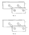
- Figure 1 illustrates two examples of magnetic attachment of a mobile electronic device to a vehicle audio device wherein the former comprises a permanent magnet in form of a plate and the latter comprises an iron yoke plate ( Figure 1 a) or wherein both devices comprise permanent magnets ( Figure 1b ).
- Figure 1 a shows an iron yoke plate 1 that represents a radio face plate of a car radio installed in the passenger compartment of an automobile. Both the yoke plate and the face plate may be brushed, anodized or varnished in accordance with particular design specifications.
- a permanent magnet plate 2 being a part of a mobile electronic device that is to be attached to the car radio.
- the mobile electronic device is a portable personal navigation device, e.g., a Becker Traffic Assist Pro 7929.
- the permanent magnet plate 2 is fixed at the back surface of the portable personal navigation device.
- the portable personal navigation device can easily be attached to as well as detached from the car radio by means of the magnetic force exerted between the iron yoke plate 1 and the permanent magnet plate 2.
- the radio face plate 1 can, thus, be formed in a smooth and aesthetically pleasing manner and can be freely designed without any limitation by mechanical elements that are needed in the art for the attachment of any mobile device to the car radio.
- the car radio could be provided with the permanent magnet rather than the yoke plate and the mobile electronic device could be provided with the yoke plate rather than the permanent magnet for facilitating the magnetic attachment.
- Figure 1b shows another example for the inventive magnetic attachment of a mobile device to a vehicle audio device.
- the radio front plate 1 is built from a permanent magnet with the magnet south pole directed away from the radio device (i.e. in the direction to the interior of the vehicle compartment).
- the mobile device comprises a permanent magnet plate 2 at the back surface with the magnetic north pole directed away from the back surface.
- the magnetic south pole of the radio front plate 1 and the magnetic north pole of the permanent magnet plate 2 of the mobile electronic device are opposed to each other thereby facilitating magnetic attachment of the mobile electronic device to the car radio (or a different audio device installed in a vehicle compartment).
- the magnetic poles could be arranged vice versa, i.e. south pole and north pole can be interchanged.
- both plates may comprise a number of permanent magnets with alternating magnetic south and north poles opposed to the respective magnetic poles of the respective other plate.
- the radio front plate 1 may comprise a number of permanent magnets arranged such that some of the magnets have the magnetic south poles and other have the magnetic north poles outwardly directed.
- the permanent magnet plate 2 of the mobile electronic device matches the radio front plate 1 such that magnetic south poles of permanent magnets directed away from the back surface of the mobile electronic device are opposed by magnetic north poles of the radio front plate 1 in the state of attachment.
- the permanent magnets can, e.g., be made of alloys of Fe, Co, Mn, Cu or of ceramic oxides as barium or iron oxide.
- the permanent magnets may also be rare earth magnets, e.g., a neodymium-iron-boron compound, providing strong but relatively expensive magnets.
- the radio face plate may itself represent a permanent magnet or one or more magnets may be embedded in the radio face plate or it may be coated with a permanent magnet film. The same holds for the permanent magnet plate of the personal navigation device.
Landscapes
- Engineering & Computer Science (AREA)
- Radar, Positioning & Navigation (AREA)
- Remote Sensing (AREA)
- Mechanical Engineering (AREA)
- Automation & Control Theory (AREA)
- Physics & Mathematics (AREA)
- General Physics & Mathematics (AREA)
- Fittings On The Vehicle Exterior For Carrying Loads, And Devices For Holding Or Mounting Articles (AREA)
Abstract

Description
- The present invention relates to a vehicle audio device, e.g., a car radio, installed in a vehicle and attachment of a mobile electronic device to the vehicle audio device.
- In recent years the combination and mechanical and electrical connection of different electronic devices in vehicles, in particular, in automobiles, became an issue of growing importance (car multimedia). In particular, there is an increasing need or at least request for a reliable and simple attachment of a mobile device, e.g., a personal navigation device, to a fixed audio device, e.g., a car radio, that is already installed in the vehicle.
- In the art, different mechanical attachment means for attaching a mobile device to an audio device installed in a vehicle compartment are known. Such mechanical attachment means typically including a number of mechanical elements as, e.g., springs, knurls, gudgeons, pivots, notches and screws, that are relatively expansive and result in rather complicated mechansims. Moreover, mechanical attachment means bear the risk of breakage and inevitably suffer from mechanical wear. Presently employed lock and release mechanisms are uncomfortable in handling and due to the mechanical wear the handling properties deteriorate in the course of the service life.
- In addition, known mechanical attachment means not only affect the aesthetic appearance of the vehicle audio devices but also affect the product design due to protruding mechanical elements or slots, etc.
- It is, therefore, an object of the present invention to provide a solution of the problem of a reliable, fast and simple attachment of a mobile electronic device to an audio device already installed in a vehicle compartment that overcomes the above-mentioned drawbacks of the art.
- The above-mentioned problem is solved by magnetic attachment of a mobile electronic device to a vehicle audio device that is already installed in a passenger compartment of a vehicle, in particular, an automobile.
- The present invention provides a vehicle audio device (i.e. an audio device installed in a vehicle, in particular, an automobile) comprising magnetic means for attachment of a mobile electronic device to the vehicle audio device. Whereas it is known that the magnetic force can be used for attachment of one particular object to another, it is not considered in the art to provide an audio device installed in a vehicle compartment with magnet means for attaching a mobile electronic device. By this magnetic means the necessity for expensive, accident-sensitive and uncomfortable mechanical fasteners, clamps and fittings is overcome. The product design is no longer limited with regard to mechanical attachment means.
- According to one embodiment, the magnetic means for attaching a mobile electronic device comprises a permanent magnet, e.g., made of an alloy of iron and/or copper, or a yoke plate, in particular, an iron plate. The permanent magnet can also be in the form of a plate. The permanent magnet and the yoke plate can be provided at the front of the vehicle audio device, e.g., in form of a face plate arranged below or above or alongside an operation section of the audio device that may comprise buttons and/or switches. Moreover, the permanent magnet and the yoke plate can be embedded in the mobile electronic device or the vehicle audio device, respectively. In particular, the permanent magnet and the yoke plate can be casted integral with a housing of the mobile electronic device or the vehicle audio device, respectively, that is made of plastic material.
- Such a permanent magnet and a yoke plate represent simple and inexpensive means for magnet attachment. A yoke plate can be used, if the mobile electronic device that is to be attached to the vehicle audio device is provided with a permanent magnet.
- The disclosed magnetic attachment is particularly useful for a car radio (being the above-mentioned vehicle audio device). By the magnetic attachment means any mobile electronic device can be attached to the car radio which is usually installed at a prominent position in the vehicular cabin of an automobile. Attachment of a mobile device to a car radio, thus, is desirable in terms of operation of the mobile device either by a driver or front passenger. At the position at or close to the vehicle audio device the mobile electronic device can readily be operated and a display on the mobile electronic device can easily be seen by the driver and a front passenger.
- Moreover, the vehicle audio device may comprise electrical connections (contacts) for connection with the mobile electronic device. In this case the mobile electronic device is not only magnetically attached to the vehicle audio device (e.g., a car radio) but can also communicate with the latter after attachment by means of the electrical connections. In particular, the electrical connections may comprise a connection for electric power supply. Thus, the mobile device can be charged by the car battery via the vehicle audio device that it is magnetically attached to.
- Additionally or alternatively the vehicle audio device may be provided with contacts that enable activation of some radio link to the mobile electronic device, e.g., by means of the Bluetooth or WLAN technology. These contacts may be pressure sensitive or magnetic contacts that allow for activation of the radio link in response to the attachment of the mobile electronic device. Of course, an infrared link may be provided rather than or in addition to the radio link. Combined usage of different electronic devices (one fixed in the vehicle, the other one temporarily attached to the first one) is facilitated by the magnetic attachment supplemented by some communication link between the electronic devices.
- According to another embodiment the above-described examples for the inventive vehicle audio device further comprise an adjustment aid configured to adjust the mobile electronic device at the vehicle audio device. Such an adjustment aid can secure the mobile device and facilitate accurate positioning. Notches, slots and collars may be used as the adjustment aid. For example, a circumferential ridge may be provided on a magnetic radio face plate.
- It has to be stressed, however, that the adjustment aid differs from mechanical attachment means of the art in that the adjusting elements/portions are made much smaller, weaker and much more unobtrusive. This is enabled by the magnetic attachment means that mainly guarantees attachment of the mobile electronic device to the vehicle audio device.
- The adjustment aid is configured to only provide some fine-adjustment and can be formed without affecting the aesthetic appearance of the vehicle audio device. It can even be integrated in and play a part in some pleasuring design.
- The present invention also provides a mobile electronic device comprising magnetic means for attachment to a vehicle audio device. The magnetic means for attachment to a vehicle audio device may comprise a permanent magnet or a yoke plate, in particular, an iron yoke plate. The yoke plate can be used for magnetic attachment in the case that the vehicle audio device is provided with a permanent magnet. Such a mobile electronic device can be readily attached to the vehicle audio device, in particular, a car radio.
- It may be preferred to provide both the vehicle audio device and the mobile electronic device with a permanent magnet plate. In this case, a radio face plate, e.g., can have the magnetic north pole directed away from the car radio that comprises the face plate (directed in to interior of the passenger compartment of the vehicle) and the mobile electronic device can comprise a back plate made of the permanent magnet with the magnetic south pole directed away from the mobile device. Reverse polarization is, of course, also possible.
- Moreover, it may be preferred that the vehicle audio device and/or the mobile electronic device comprise more than one permanent magnet. Permanent magnets can be distributed in contact surfaces at which both devices contact each other in the state of attachment. Polarization of the multiple permanent magnets may differ in each of the contact surfaces and it is only to be guaranteed that in the state of attachment south and north poles of the respective permanent magnets of the vehicle radio device and the mobile electronic device face each other.
- Magnetic attachment of the mobile electronic device is particularly useful for a personal navigation device. Personal navigation devices become increasingly prevalent in recent years. In the art attachment of this kind of navigation aids is, however, difficult. Moreover, the driver must be enabled to watch an optical display (if present) of the personal navigation device. Therefore, magnetic attachment of a personal navigation device to a car radio is advantageous.
- The mobile electronic device may further comprise electrical connections for connection with the vehicle audio device. Electrical connections as well as means for a radio/IR link with the vehicle audio device can be provided for the mobile electronic device similar as discussed above for the case of the vehicle audio device in order to establish a communication channel between both devices.
- The present invention also provides a vehicle communication system, comprising
- a vehicle audio device, in particular, a car radio, according to one of the above examples;
- a mobile electronic device, in particular, a personal navigation device, according to one of the above examples;
- The above-mentioned problem is solved by a method for attaching a mobile electronic device to a vehicle audio device comprising the steps of a) providing magnetic means for magnetically attaching the mobile electronic device to the vehicle audio device and b) magnetically attaching the mobile electronic device to the vehicle audio device by the provided magnetic means.
- According to an embodiment the mobile electronic device is provided with a first permanent magnet and the vehicle audio device is provided with a yoke plate or a second permanent magnet and wherein the mobile electronic device is attached to the yoke plate or the second permanent magnet of the vehicle audio device by means of the first permanent magnet or the mobile electronic device is provided with a yoke plate and the vehicle audio device is provided with a permanent magnet and wherein the mobile electronic device is attached to the permanent magnet of the vehicle audio device.
- The method for attaching a mobile electronic device to a vehicle audio device may further comprise electrically connecting the mobile electronic device and the vehicle audio device. Moreover, a radio or IR link may be established between both devices.
- The present invention also provides a vehicle compartment (passenger compartment of a vehicle, in particular, an automobile) comprising a vehicle audio device according to one of the examples above that is installed in the vehicle compartment and a mobile electronic device according to one of the examples above that is magnetically attached to the vehicle audio device.
- Additional features and advantages of the present invention will be described with reference to the drawing. In the description, reference is made to the accompanying figure that is meant to illustrate preferred embodiments of the invention. It is understood that such embodiments do not represent the full scope of the invention.
-
Figure 1 illustrates two examples of magnetic attachment of a mobile electronic device to a vehicle audio device wherein the former comprises a permanent magnet in form of a plate and the latter comprises an iron yoke plate (Figure 1 a) or wherein both devices comprise permanent magnets (Figure 1b ). -
Figure 1 a shows aniron yoke plate 1 that represents a radio face plate of a car radio installed in the passenger compartment of an automobile. Both the yoke plate and the face plate may be brushed, anodized or varnished in accordance with particular design specifications. InFigure 1 a it is also shown apermanent magnet plate 2 being a part of a mobile electronic device that is to be attached to the car radio. In the present example, the mobile electronic device is a portable personal navigation device, e.g., a Becker Traffic Assist Pro 7929. Thepermanent magnet plate 2 is fixed at the back surface of the portable personal navigation device. - The portable personal navigation device can easily be attached to as well as detached from the car radio by means of the magnetic force exerted between the
iron yoke plate 1 and thepermanent magnet plate 2. - The
radio face plate 1 can, thus, be formed in a smooth and aesthetically pleasing manner and can be freely designed without any limitation by mechanical elements that are needed in the art for the attachment of any mobile device to the car radio. Of course, the car radio could be provided with the permanent magnet rather than the yoke plate and the mobile electronic device could be provided with the yoke plate rather than the permanent magnet for facilitating the magnetic attachment. -
Figure 1b shows another example for the inventive magnetic attachment of a mobile device to a vehicle audio device. Here, theradio front plate 1 is built from a permanent magnet with the magnet south pole directed away from the radio device (i.e. in the direction to the interior of the vehicle compartment). Correspondingly, the mobile device comprises apermanent magnet plate 2 at the back surface with the magnetic north pole directed away from the back surface. Thus, the magnetic south pole of theradio front plate 1 and the magnetic north pole of thepermanent magnet plate 2 of the mobile electronic device are opposed to each other thereby facilitating magnetic attachment of the mobile electronic device to the car radio (or a different audio device installed in a vehicle compartment). The magnetic poles could be arranged vice versa, i.e. south pole and north pole can be interchanged. - According to another example, both plates may comprise a number of permanent magnets with alternating magnetic south and north poles opposed to the respective magnetic poles of the respective other plate. In other words, the
radio front plate 1 may comprise a number of permanent magnets arranged such that some of the magnets have the magnetic south poles and other have the magnetic north poles outwardly directed. Thepermanent magnet plate 2 of the mobile electronic device matches theradio front plate 1 such that magnetic south poles of permanent magnets directed away from the back surface of the mobile electronic device are opposed by magnetic north poles of theradio front plate 1 in the state of attachment. By such an arrangement a more secure attachment may be achieved. - In the above described examples the permanent magnets can, e.g., be made of alloys of Fe, Co, Mn, Cu or of ceramic oxides as barium or iron oxide. In principle, the permanent magnets may also be rare earth magnets, e.g., a neodymium-iron-boron compound, providing strong but relatively expensive magnets. The radio face plate may itself represent a permanent magnet or one or more magnets may be embedded in the radio face plate or it may be coated with a permanent magnet film. The same holds for the permanent magnet plate of the personal navigation device.
- All previously discussed embodiments are not intended as limitations but serve as examples illustrating features and advantages of the invention. It is to be understood that some or all of the above described features can also be combined in different ways.
Claims (15)
- Vehicle audio device comprising magnetic means for attachment of a mobile electronic device to the vehicle audio device.
- Vehicle audio device according to claim 1, wherein the magnetic means comprises a permanent magnet or a yoke plate, in particular, an iron plate.
- Vehicle audio device according to claim 1 or 2, wherein the vehicle audio device is a car radio.
- Vehicle audio device according to one of the preceding claims, further comprising electrical connections for connection with the mobile electronic device.
- Vehicle audio device according to one of the preceding claims, further comprising an adjustment aid configured to adjust the mobile electronic device at the vehicle audio device.
- Mobile electronic device comprising magnetic means for attachment to a vehicle audio device.
- Mobile electronic device according to claim 6, wherein the magnetic means for attachment to the vehicle audio device comprises a permanent magnet or a yoke plate, in particular, an iron plate.
- Mobile electronic device according to claim 6 or 7, wherein the mobile electronic device is a personal navigation device.
- Mobile electronic device according to one of the claims 6 to 8, wherein the mobile electronic device further comprises electrical connections for connection with the vehicle audio device.
- Mobile electronic device according to claim 9, wherein the electrical connections comprise a connection for electric power supply.
- Method for attaching a mobile electronic device to a vehicle audio device, comprisingproviding magnetic means for magnetically attaching the mobile electronic device to the vehicle audio device; andmagnetically attaching the mobile electronic device to the vehicle audio device by the provided magnetic means.
- Method according to claim 11, wherein
the mobile electronic device is provided with a first permanent magnet and the vehicle audio device is provided with a yoke plate or a second permanent magnet and wherein the mobile electronic device is attached to the yoke plate or the second permanent magnet of the vehicle audio device by means of the first permanent magnet; or
the mobile electronic device is provided with a yoke plate and the vehicle audio device is provided with a permanent magnet and wherein the mobile electronic device is attached to the permanent magnet of the vehicle audio device. - Method according to claim 11 or 12, further comprising electrically connecting the mobile electronic device and the vehicle audio device.
- Vehicle communication system, comprisinga vehicle audio device, in particular, a car radio, according to one of the claims 1 to 5;a mobile electronic device, in particular, a personal navigation device, according to one of the claims 6 to 10;wherein the mobile electronic device is magnetically attachable to and detachable from the vehicle audio device.
- Vehicle compartment comprising a vehicle audio device according to one of the claims 1 to 5 installed in the vehicle compartment and a mobile electronic device according to one of the claims 6 to 10 magnetically attached to the vehicle audio device according to one of the claims 1 to 5.
Priority Applications (3)
| Application Number | Priority Date | Filing Date | Title |
|---|---|---|---|
| EP07001749A EP1950093B1 (en) | 2007-01-26 | 2007-01-26 | Attachment of a mobile electronic device to a vehicle audio device |
| AT07001749T ATE512833T1 (en) | 2007-01-26 | 2007-01-26 | ATTACHING A MOBILE ELECTRONIC DEVICE TO A VEHICLE AUDIO DEVICE |
| EP07013774A EP1950094B1 (en) | 2007-01-26 | 2007-07-13 | A system for mounting a mobile electronic device |
Applications Claiming Priority (1)
| Application Number | Priority Date | Filing Date | Title |
|---|---|---|---|
| EP07001749A EP1950093B1 (en) | 2007-01-26 | 2007-01-26 | Attachment of a mobile electronic device to a vehicle audio device |
Publications (2)
| Publication Number | Publication Date |
|---|---|
| EP1950093A1 true EP1950093A1 (en) | 2008-07-30 |
| EP1950093B1 EP1950093B1 (en) | 2011-06-15 |
Family
ID=38969481
Family Applications (1)
| Application Number | Title | Priority Date | Filing Date |
|---|---|---|---|
| EP07001749A Not-in-force EP1950093B1 (en) | 2007-01-26 | 2007-01-26 | Attachment of a mobile electronic device to a vehicle audio device |
Country Status (2)
| Country | Link |
|---|---|
| EP (1) | EP1950093B1 (en) |
| AT (1) | ATE512833T1 (en) |
Cited By (2)
| Publication number | Priority date | Publication date | Assignee | Title |
|---|---|---|---|---|
| WO2012018695A1 (en) * | 2010-08-02 | 2012-02-09 | Qualcomm Incorporated | Pnd repositioning detector for better navigation accuracy in a car |
| CN104354650A (en) * | 2014-10-31 | 2015-02-18 | 成都众易通科技有限公司 | Mounting device for vehicle-mounted GPS (Global Position System) positioner |
Citations (5)
| Publication number | Priority date | Publication date | Assignee | Title |
|---|---|---|---|---|
| US4058357A (en) * | 1976-03-31 | 1977-11-15 | Wallace Dewey K | Magnetic radio mounting bracket |
| DE19746161A1 (en) * | 1997-07-25 | 1999-04-29 | E Lead Electronic Co Ltd | Cellular telephone and automobile acoustic unit combination equipment for automobile interior |
| US20020137541A1 (en) * | 2001-03-22 | 2002-09-26 | Lepley Geoffrey Peter | Dual-function removable reversable unit for radio and telephone |
| DE10125063A1 (en) * | 2001-05-23 | 2002-12-12 | Bosch Gmbh Robert | Holder for a portable computing device |
| WO2004083658A1 (en) * | 2003-03-17 | 2004-09-30 | Koninklijke Philips Electronics N.V. | Flat panel display unit provided with attachment means and attachment unit for the removable attachment of an object |
-
2007
- 2007-01-26 AT AT07001749T patent/ATE512833T1/en not_active IP Right Cessation
- 2007-01-26 EP EP07001749A patent/EP1950093B1/en not_active Not-in-force
Patent Citations (5)
| Publication number | Priority date | Publication date | Assignee | Title |
|---|---|---|---|---|
| US4058357A (en) * | 1976-03-31 | 1977-11-15 | Wallace Dewey K | Magnetic radio mounting bracket |
| DE19746161A1 (en) * | 1997-07-25 | 1999-04-29 | E Lead Electronic Co Ltd | Cellular telephone and automobile acoustic unit combination equipment for automobile interior |
| US20020137541A1 (en) * | 2001-03-22 | 2002-09-26 | Lepley Geoffrey Peter | Dual-function removable reversable unit for radio and telephone |
| DE10125063A1 (en) * | 2001-05-23 | 2002-12-12 | Bosch Gmbh Robert | Holder for a portable computing device |
| WO2004083658A1 (en) * | 2003-03-17 | 2004-09-30 | Koninklijke Philips Electronics N.V. | Flat panel display unit provided with attachment means and attachment unit for the removable attachment of an object |
Cited By (6)
| Publication number | Priority date | Publication date | Assignee | Title |
|---|---|---|---|---|
| WO2012018695A1 (en) * | 2010-08-02 | 2012-02-09 | Qualcomm Incorporated | Pnd repositioning detector for better navigation accuracy in a car |
| CN103052864A (en) * | 2010-08-02 | 2013-04-17 | 高通股份有限公司 | Pnd repositioning detector for better navigation accuracy in a car |
| US8818718B2 (en) | 2010-08-02 | 2014-08-26 | Qualcomm Incorporated | PND repositioning detector for better navigation accuracy in a car |
| CN103052864B (en) * | 2010-08-02 | 2016-03-23 | 高通股份有限公司 | For the PND reorientation detecting device of the better navigation accuracy in automobile |
| CN104354650A (en) * | 2014-10-31 | 2015-02-18 | 成都众易通科技有限公司 | Mounting device for vehicle-mounted GPS (Global Position System) positioner |
| CN104354650B (en) * | 2014-10-31 | 2016-05-18 | 成都众易通科技有限公司 | A kind of vehicle GPS locator erecting device |
Also Published As
| Publication number | Publication date |
|---|---|
| EP1950093B1 (en) | 2011-06-15 |
| ATE512833T1 (en) | 2011-07-15 |
Similar Documents
| Publication | Publication Date | Title |
|---|---|---|
| CN101689717B (en) | Headphone Connector System | |
| US20080258585A1 (en) | Resolver | |
| EP2993765B1 (en) | Motor device | |
| WO2008019054A3 (en) | Electromotive device | |
| JP2011502879A (en) | Magnet device for supporting portable electronic devices, especially in cars | |
| TW200528322A (en) | Buckle switch and buckle device | |
| KR200494737Y1 (en) | Magnetic Wireless Charging Mobile Phone Holder For Motorcycle | |
| EP1950093B1 (en) | Attachment of a mobile electronic device to a vehicle audio device | |
| WO2014184610A1 (en) | Magnetic coupling of an accessory device to a portable electronic device | |
| US20250256659A1 (en) | Fixed Angle Car Mount for a Mobile Device | |
| US20160286294A1 (en) | Hang up magnet for radio microphone | |
| EP1467436A3 (en) | Antenna device for vehicles and vehicle antenna system and communication system using the antenna device | |
| JP2020098410A (en) | Vehicle brake rotation angle detection device and vehicle brake control system | |
| US7396235B2 (en) | Modular electronic device | |
| US11287030B2 (en) | Shift device | |
| US20090102299A1 (en) | Transmission/Drive Unit With A Symmetrically Positioned Connecting Plug | |
| EP1950094B1 (en) | A system for mounting a mobile electronic device | |
| US20140327345A1 (en) | Noise shield unit in wound rotor synchronous motor (wrsm) motor | |
| US20230391274A1 (en) | Magnetic Mic Mount Device | |
| US7536207B2 (en) | Mobile terminal having round external speaker | |
| CN112046408A (en) | Slide fixing device for vehicle electronic equipment, control method thereof and vehicle | |
| CN116176705B (en) | A car with replaceable upper body and chassis thereof | |
| CN107454541B (en) | Telephone receiver and assembling method thereof | |
| US20170311463A1 (en) | Electronics housing | |
| CN201118411Y (en) | Permanent magnetic DC brush electromotor |
Legal Events
| Date | Code | Title | Description |
|---|---|---|---|
| PUAI | Public reference made under article 153(3) epc to a published international application that has entered the european phase |
Free format text: ORIGINAL CODE: 0009012 |
|
| 17P | Request for examination filed |
Effective date: 20080304 |
|
| AK | Designated contracting states |
Kind code of ref document: A1 Designated state(s): AT BE BG CH CY CZ DE DK EE ES FI FR GB GR HU IE IS IT LI LT LU LV MC NL PL PT RO SE SI SK TR |
|
| AX | Request for extension of the european patent |
Extension state: AL BA HR MK RS |
|
| AKX | Designation fees paid |
Designated state(s): AT BE BG CH CY CZ DE DK EE ES FI FR GB GR HU IE IS IT LI LT LU LV MC NL PL PT RO SE SI SK TR |
|
| 17Q | First examination report despatched |
Effective date: 20090728 |
|
| GRAP | Despatch of communication of intention to grant a patent |
Free format text: ORIGINAL CODE: EPIDOSNIGR1 |
|
| GRAS | Grant fee paid |
Free format text: ORIGINAL CODE: EPIDOSNIGR3 |
|
| GRAA | (expected) grant |
Free format text: ORIGINAL CODE: 0009210 |
|
| AK | Designated contracting states |
Kind code of ref document: B1 Designated state(s): AT BE BG CH CY CZ DE DK EE ES FI FR GB GR HU IE IS IT LI LT LU LV MC NL PL PT RO SE SI SK TR |
|
| REG | Reference to a national code |
Ref country code: GB Ref legal event code: FG4D Ref country code: CH Ref legal event code: EP |
|
| REG | Reference to a national code |
Ref country code: IE Ref legal event code: FG4D |
|
| REG | Reference to a national code |
Ref country code: DE Ref legal event code: R096 Ref document number: 602007015157 Country of ref document: DE Effective date: 20110721 |
|
| REG | Reference to a national code |
Ref country code: NL Ref legal event code: VDEP Effective date: 20110615 |
|
| PG25 | Lapsed in a contracting state [announced via postgrant information from national office to epo] |
Ref country code: LT Free format text: LAPSE BECAUSE OF FAILURE TO SUBMIT A TRANSLATION OF THE DESCRIPTION OR TO PAY THE FEE WITHIN THE PRESCRIBED TIME-LIMIT Effective date: 20110615 Ref country code: SE Free format text: LAPSE BECAUSE OF FAILURE TO SUBMIT A TRANSLATION OF THE DESCRIPTION OR TO PAY THE FEE WITHIN THE PRESCRIBED TIME-LIMIT Effective date: 20110615 |
|
| PG25 | Lapsed in a contracting state [announced via postgrant information from national office to epo] |
Ref country code: SI Free format text: LAPSE BECAUSE OF FAILURE TO SUBMIT A TRANSLATION OF THE DESCRIPTION OR TO PAY THE FEE WITHIN THE PRESCRIBED TIME-LIMIT Effective date: 20110615 Ref country code: AT Free format text: LAPSE BECAUSE OF FAILURE TO SUBMIT A TRANSLATION OF THE DESCRIPTION OR TO PAY THE FEE WITHIN THE PRESCRIBED TIME-LIMIT Effective date: 20110615 Ref country code: CY Free format text: LAPSE BECAUSE OF FAILURE TO SUBMIT A TRANSLATION OF THE DESCRIPTION OR TO PAY THE FEE WITHIN THE PRESCRIBED TIME-LIMIT Effective date: 20110615 Ref country code: LV Free format text: LAPSE BECAUSE OF FAILURE TO SUBMIT A TRANSLATION OF THE DESCRIPTION OR TO PAY THE FEE WITHIN THE PRESCRIBED TIME-LIMIT Effective date: 20110615 Ref country code: GR Free format text: LAPSE BECAUSE OF FAILURE TO SUBMIT A TRANSLATION OF THE DESCRIPTION OR TO PAY THE FEE WITHIN THE PRESCRIBED TIME-LIMIT Effective date: 20110916 Ref country code: FI Free format text: LAPSE BECAUSE OF FAILURE TO SUBMIT A TRANSLATION OF THE DESCRIPTION OR TO PAY THE FEE WITHIN THE PRESCRIBED TIME-LIMIT Effective date: 20110615 |
|
| PG25 | Lapsed in a contracting state [announced via postgrant information from national office to epo] |
Ref country code: NL Free format text: LAPSE BECAUSE OF FAILURE TO SUBMIT A TRANSLATION OF THE DESCRIPTION OR TO PAY THE FEE WITHIN THE PRESCRIBED TIME-LIMIT Effective date: 20110615 Ref country code: BE Free format text: LAPSE BECAUSE OF FAILURE TO SUBMIT A TRANSLATION OF THE DESCRIPTION OR TO PAY THE FEE WITHIN THE PRESCRIBED TIME-LIMIT Effective date: 20110615 |
|
| PG25 | Lapsed in a contracting state [announced via postgrant information from national office to epo] |
Ref country code: PT Free format text: LAPSE BECAUSE OF FAILURE TO SUBMIT A TRANSLATION OF THE DESCRIPTION OR TO PAY THE FEE WITHIN THE PRESCRIBED TIME-LIMIT Effective date: 20111017 Ref country code: EE Free format text: LAPSE BECAUSE OF FAILURE TO SUBMIT A TRANSLATION OF THE DESCRIPTION OR TO PAY THE FEE WITHIN THE PRESCRIBED TIME-LIMIT Effective date: 20110615 Ref country code: IS Free format text: LAPSE BECAUSE OF FAILURE TO SUBMIT A TRANSLATION OF THE DESCRIPTION OR TO PAY THE FEE WITHIN THE PRESCRIBED TIME-LIMIT Effective date: 20111015 Ref country code: CZ Free format text: LAPSE BECAUSE OF FAILURE TO SUBMIT A TRANSLATION OF THE DESCRIPTION OR TO PAY THE FEE WITHIN THE PRESCRIBED TIME-LIMIT Effective date: 20110615 |
|
| PG25 | Lapsed in a contracting state [announced via postgrant information from national office to epo] |
Ref country code: PL Free format text: LAPSE BECAUSE OF FAILURE TO SUBMIT A TRANSLATION OF THE DESCRIPTION OR TO PAY THE FEE WITHIN THE PRESCRIBED TIME-LIMIT Effective date: 20110615 Ref country code: RO Free format text: LAPSE BECAUSE OF FAILURE TO SUBMIT A TRANSLATION OF THE DESCRIPTION OR TO PAY THE FEE WITHIN THE PRESCRIBED TIME-LIMIT Effective date: 20110615 Ref country code: SK Free format text: LAPSE BECAUSE OF FAILURE TO SUBMIT A TRANSLATION OF THE DESCRIPTION OR TO PAY THE FEE WITHIN THE PRESCRIBED TIME-LIMIT Effective date: 20110615 |
|
| PLBE | No opposition filed within time limit |
Free format text: ORIGINAL CODE: 0009261 |
|
| STAA | Information on the status of an ep patent application or granted ep patent |
Free format text: STATUS: NO OPPOSITION FILED WITHIN TIME LIMIT |
|
| 26N | No opposition filed |
Effective date: 20120316 |
|
| PG25 | Lapsed in a contracting state [announced via postgrant information from national office to epo] |
Ref country code: IT Free format text: LAPSE BECAUSE OF FAILURE TO SUBMIT A TRANSLATION OF THE DESCRIPTION OR TO PAY THE FEE WITHIN THE PRESCRIBED TIME-LIMIT Effective date: 20110615 |
|
| PG25 | Lapsed in a contracting state [announced via postgrant information from national office to epo] |
Ref country code: DK Free format text: LAPSE BECAUSE OF FAILURE TO SUBMIT A TRANSLATION OF THE DESCRIPTION OR TO PAY THE FEE WITHIN THE PRESCRIBED TIME-LIMIT Effective date: 20110615 |
|
| REG | Reference to a national code |
Ref country code: DE Ref legal event code: R097 Ref document number: 602007015157 Country of ref document: DE Effective date: 20120316 |
|
| PG25 | Lapsed in a contracting state [announced via postgrant information from national office to epo] |
Ref country code: MC Free format text: LAPSE BECAUSE OF NON-PAYMENT OF DUE FEES Effective date: 20120131 |
|
| REG | Reference to a national code |
Ref country code: CH Ref legal event code: PL |
|
| REG | Reference to a national code |
Ref country code: IE Ref legal event code: MM4A |
|
| PG25 | Lapsed in a contracting state [announced via postgrant information from national office to epo] |
Ref country code: CH Free format text: LAPSE BECAUSE OF NON-PAYMENT OF DUE FEES Effective date: 20120131 Ref country code: LI Free format text: LAPSE BECAUSE OF NON-PAYMENT OF DUE FEES Effective date: 20120131 |
|
| PG25 | Lapsed in a contracting state [announced via postgrant information from national office to epo] |
Ref country code: IE Free format text: LAPSE BECAUSE OF NON-PAYMENT OF DUE FEES Effective date: 20120126 |
|
| PG25 | Lapsed in a contracting state [announced via postgrant information from national office to epo] |
Ref country code: ES Free format text: LAPSE BECAUSE OF FAILURE TO SUBMIT A TRANSLATION OF THE DESCRIPTION OR TO PAY THE FEE WITHIN THE PRESCRIBED TIME-LIMIT Effective date: 20110926 |
|
| PG25 | Lapsed in a contracting state [announced via postgrant information from national office to epo] |
Ref country code: BG Free format text: LAPSE BECAUSE OF FAILURE TO SUBMIT A TRANSLATION OF THE DESCRIPTION OR TO PAY THE FEE WITHIN THE PRESCRIBED TIME-LIMIT Effective date: 20110915 |
|
| PG25 | Lapsed in a contracting state [announced via postgrant information from national office to epo] |
Ref country code: TR Free format text: LAPSE BECAUSE OF FAILURE TO SUBMIT A TRANSLATION OF THE DESCRIPTION OR TO PAY THE FEE WITHIN THE PRESCRIBED TIME-LIMIT Effective date: 20110615 |
|
| PG25 | Lapsed in a contracting state [announced via postgrant information from national office to epo] |
Ref country code: LU Free format text: LAPSE BECAUSE OF NON-PAYMENT OF DUE FEES Effective date: 20120126 |
|
| PG25 | Lapsed in a contracting state [announced via postgrant information from national office to epo] |
Ref country code: HU Free format text: LAPSE BECAUSE OF FAILURE TO SUBMIT A TRANSLATION OF THE DESCRIPTION OR TO PAY THE FEE WITHIN THE PRESCRIBED TIME-LIMIT Effective date: 20070126 |
|
| REG | Reference to a national code |
Ref country code: FR Ref legal event code: PLFP Year of fee payment: 10 |
|
| PGFP | Annual fee paid to national office [announced via postgrant information from national office to epo] |
Ref country code: DE Payment date: 20160127 Year of fee payment: 10 |
|
| PGFP | Annual fee paid to national office [announced via postgrant information from national office to epo] |
Ref country code: FR Payment date: 20160126 Year of fee payment: 10 Ref country code: GB Payment date: 20160127 Year of fee payment: 10 |
|
| REG | Reference to a national code |
Ref country code: DE Ref legal event code: R119 Ref document number: 602007015157 Country of ref document: DE |
|
| GBPC | Gb: european patent ceased through non-payment of renewal fee |
Effective date: 20170126 |
|
| REG | Reference to a national code |
Ref country code: FR Ref legal event code: ST Effective date: 20170929 |
|
| PG25 | Lapsed in a contracting state [announced via postgrant information from national office to epo] |
Ref country code: FR Free format text: LAPSE BECAUSE OF NON-PAYMENT OF DUE FEES Effective date: 20170131 |
|
| PG25 | Lapsed in a contracting state [announced via postgrant information from national office to epo] |
Ref country code: DE Free format text: LAPSE BECAUSE OF NON-PAYMENT OF DUE FEES Effective date: 20170801 Ref country code: GB Free format text: LAPSE BECAUSE OF NON-PAYMENT OF DUE FEES Effective date: 20170126 |
|
| P01 | Opt-out of the competence of the unified patent court (upc) registered |
Effective date: 20230526 |