EP1949983A2 - Device for manipulating treated tinplate sheets - Google Patents
Device for manipulating treated tinplate sheets Download PDFInfo
- Publication number
- EP1949983A2 EP1949983A2 EP05824287A EP05824287A EP1949983A2 EP 1949983 A2 EP1949983 A2 EP 1949983A2 EP 05824287 A EP05824287 A EP 05824287A EP 05824287 A EP05824287 A EP 05824287A EP 1949983 A2 EP1949983 A2 EP 1949983A2
- Authority
- EP
- European Patent Office
- Prior art keywords
- sheets
- tinplate
- manipulating
- treated
- manipulator arm
- Prior art date
- Legal status (The legal status is an assumption and is not a legal conclusion. Google has not performed a legal analysis and makes no representation as to the accuracy of the status listed.)
- Withdrawn
Links
- 239000005028 tinplate Substances 0.000 title claims abstract description 38
- 238000000034 method Methods 0.000 claims abstract description 17
- 230000008569 process Effects 0.000 claims abstract description 17
- 235000013305 food Nutrition 0.000 claims abstract description 4
- 238000004806 packaging method and process Methods 0.000 claims description 21
- 210000000080 chela (arthropods) Anatomy 0.000 claims description 15
- 238000005520 cutting process Methods 0.000 claims description 7
- 210000000078 claw Anatomy 0.000 claims description 6
- 238000004519 manufacturing process Methods 0.000 claims description 6
- 230000009471 action Effects 0.000 claims description 4
- 238000003860 storage Methods 0.000 claims description 3
- 230000015572 biosynthetic process Effects 0.000 claims description 2
- 230000007306 turnover Effects 0.000 claims description 2
- 230000003647 oxidation Effects 0.000 claims 1
- 238000007254 oxidation reaction Methods 0.000 claims 1
- 230000008859 change Effects 0.000 description 1
- 238000004080 punching Methods 0.000 description 1
- 238000009877 rendering Methods 0.000 description 1
- 239000013589 supplement Substances 0.000 description 1
- 239000002699 waste material Substances 0.000 description 1
Images


Classifications
-
- B—PERFORMING OPERATIONS; TRANSPORTING
- B65—CONVEYING; PACKING; STORING; HANDLING THIN OR FILAMENTARY MATERIAL
- B65H—HANDLING THIN OR FILAMENTARY MATERIAL, e.g. SHEETS, WEBS, CABLES
- B65H5/00—Feeding articles separated from piles; Feeding articles to machines
- B65H5/006—Feeding stacks of articles to machines
-
- B—PERFORMING OPERATIONS; TRANSPORTING
- B21—MECHANICAL METAL-WORKING WITHOUT ESSENTIALLY REMOVING MATERIAL; PUNCHING METAL
- B21D—WORKING OR PROCESSING OF SHEET METAL OR METAL TUBES, RODS OR PROFILES WITHOUT ESSENTIALLY REMOVING MATERIAL; PUNCHING METAL
- B21D43/00—Feeding, positioning or storing devices combined with, or arranged in, or specially adapted for use in connection with, apparatus for working or processing sheet metal, metal tubes or metal profiles; Associations therewith of cutting devices
- B21D43/20—Storage arrangements; Piling or unpiling
-
- B—PERFORMING OPERATIONS; TRANSPORTING
- B21—MECHANICAL METAL-WORKING WITHOUT ESSENTIALLY REMOVING MATERIAL; PUNCHING METAL
- B21D—WORKING OR PROCESSING OF SHEET METAL OR METAL TUBES, RODS OR PROFILES WITHOUT ESSENTIALLY REMOVING MATERIAL; PUNCHING METAL
- B21D51/00—Making hollow objects
- B21D51/16—Making hollow objects characterised by the use of the objects
- B21D51/26—Making hollow objects characterised by the use of the objects cans or tins; Closing same in a permanent manner
- B21D51/2692—Manipulating, e.g. feeding and positioning devices; Control systems
-
- B—PERFORMING OPERATIONS; TRANSPORTING
- B65—CONVEYING; PACKING; STORING; HANDLING THIN OR FILAMENTARY MATERIAL
- B65H—HANDLING THIN OR FILAMENTARY MATERIAL, e.g. SHEETS, WEBS, CABLES
- B65H2301/00—Handling processes for sheets or webs
- B65H2301/40—Type of handling process
- B65H2301/42—Piling, depiling, handling piles
- B65H2301/422—Handling piles, sets or stacks of articles
- B65H2301/4224—Gripping piles, sets or stacks of articles
-
- B—PERFORMING OPERATIONS; TRANSPORTING
- B65—CONVEYING; PACKING; STORING; HANDLING THIN OR FILAMENTARY MATERIAL
- B65H—HANDLING THIN OR FILAMENTARY MATERIAL, e.g. SHEETS, WEBS, CABLES
- B65H2555/00—Actuating means
- B65H2555/30—Multi-axis
-
- B—PERFORMING OPERATIONS; TRANSPORTING
- B65—CONVEYING; PACKING; STORING; HANDLING THIN OR FILAMENTARY MATERIAL
- B65H—HANDLING THIN OR FILAMENTARY MATERIAL, e.g. SHEETS, WEBS, CABLES
- B65H2701/00—Handled material; Storage means
- B65H2701/10—Handled articles or webs
- B65H2701/17—Nature of material
- B65H2701/173—Metal
-
- B—PERFORMING OPERATIONS; TRANSPORTING
- B65—CONVEYING; PACKING; STORING; HANDLING THIN OR FILAMENTARY MATERIAL
- B65H—HANDLING THIN OR FILAMENTARY MATERIAL, e.g. SHEETS, WEBS, CABLES
- B65H2801/00—Application field
- B65H2801/81—Packaging machines
Definitions
- the invention relates to a manipulating device that has been especially designed to pick up tinplate sheets from a receiving table and place them either upon a turning device or upon a collecting tray, in order to prevent the treated surface from being damaged in any way during the handling process.
- the object of the invention is not only to prevent the tinplate sheets from being damaged, as mentioned above, but also to ensure that the transferral between the reception zone and the zone where they are deposited is carried out in a fully automated way.
- the invention can be applied not only in the process of manufacturing packaging for food products using tinplate sheets, but also, for example, for packaging for canned preserves, foodstuffs and similar.
- Metallic cans made from tinplate sheets are used to manufacture packaging that is used for certain types of food products or similar, and once these sheets have been duly punched out, formed and attached to each other, they form a sealed and airtight container. This treatment of the inner surface of the packaging is originally carried out on the tinplate sheets prior to the punching out process and manufacturing the packaging.
- the other solution which is mechanical, uses machines that operate in a linear way, in such a way that a conveyor belt moves the sheets that have been cut by the cutting machine, from the latter to a lift that raises them so that a mechanical manipulator arm can collect them and send them to a tray that supplies the machine that manufactures the packaging.
- the problem is that said machine is invariably in a linear plane with the conveyor belt; furthermore, in the event of a decision being taken to store those sheets, the transport process to the pallets or the storage zone has to be carried out manually.
- the entire handling process takes place with the treated surface of the sheets facing upwards, which is how the machine that manufactures the packaging has to receive them, which amounts to a permanent risk of the treated surface being scratched, thereby rendering it useless for being turned into a packaging, in such a way that if one wishes to overcome this problem, the cutting machine must supply the sheets with a treated surface that faces downwards, which means that it is necessary to turn it over manually immediately before it reaches the machine that manufactures the packaging.
- the manipulating device that is the object of the invention has been devised to overcome the aforementioned problem in a completely satisfactory way, thus permitting the entire process to be carried out in a fully automated way, not only when the tinplate sheets are arranged on a pallet or on a storage tray, but also when they are arranged on a supply tower on the machine that makes the packaging, making it possible for the entire sheet manipulation process to be carried out with the treated surface facing downwards, because the sheet is automatically turned over immediately before it is supplied to the above-mentioned machine.
- the manipulating device that the invention proposes be provided with a receiving table, upon which the sheets that are supplied are placed by the cutting machine with the treated surface facing downwards, this receiving table being equipped with several channels whose number and width can be adjusted, so that they can receive the different types or sizes of sheet, with a loading zone where those sheets are placed as they are cut by the cutting machine, either directly by that machine and with the help of a worker, controlling the amount of sheet that is laid on each channel with the aid of a piling height detector, which controls a lift that raises the pile, which is moved to the opposite side of the receiving table, where the pile is then lowered so it can be placed on a support, these supports correspond to different channels on the receiving table, alternately adopting different heights, so that the blocks or packs of sheets are also arranged in a staggered formation, which makes it easier for them to be gripped for the next manipulation.
- a manipulator arm moves the sheets from the receiving table either to the unloading zone of the machine that makes the packaging, or to a collection tray or pallet.
- This manipulator arm is equipped with a claw with pincers and wheels lined with rubber, adaptable pincers whose width can be adjusted to cope with different sheet formats, the pincers being aided by adjustable clamping devices that sandwich the tinplate sheets as soon as the pincers have closed, by means of a pneumatic cylinder, and the above-mentioned manipulator arm can be moved in the direction of the axes of a system of rectangular coordinates, while also being able to rotate at the same time.
- the unloading zone is equipped with a turning device, composed of a claw that is very similar to the one on the manipulator arm, but in this case it is mounted between two points on an axis that enables a rotation actuator to carry out the turning over action.
- the claw has been designed in such a way that it carries out a raising movement beforehand, so that it can find a zone that is free of obstruction and perform the turning over action, before descending towards the desired unloading position.
- the manipulating device is equipped with a collection tray, which enables it to store blocks of tinplate sheets with different lithoprinting, with as many possibilities as there are channels on the receiving table, this collection tray being assisted by a pneumatic cylinder that enable the tinplate sheets to be moved outside, so they can eventually be removed by a person.
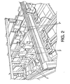
- Figures 1 and 2 show the receiving table, where there is a loading zone (1) and an unloading zone (2), set side by side.
- a series of channels (3), (3') and (3") are arranged on the loading zone (1), their purpose being to receive piles of tinplate sheets, each channel being formed by a pair of parallel strips, the distance between these strips being adjustable, so that they can adapt to the different sheet sizes.
- the number of sheets that are positioned on each channel (3) is controlled by a pile detector (4), in such a way that when the maximum number is reached, the channels (3) are raised by means of a pneumatic cylinder (5), and another pneumatic cylinder (6) moves the tinplate sheets to the zone (2), where they are placed on a series of supports (7), (7'), (7"), etc., the number of these being the same as the number of channels (3) that are established in the loading zone (1) and their positions coinciding, but with the peculiarity that these supports (7) are at different heights, as can be seen perfectly in Figure 2 , forming a staggered arrangement for the different piles of tinplate sheets lying on them, which makes it easy for the manipulator arm shown in Figure 3 to grip these blocks of sheets.
- the aforementioned manipulator arm (8) suspended from the structure (9) of the manipulating device on a position that is considerably raised with respect to the receiving table (1 - 2), is a kind of claw equipped with pincers (10), completed with a pair of wheels (11) lined with rubber so that they do not damage the tinplate sheets during the manipulation process, the width of the pincers (10) being adjustable by means of a guiding and interlocking system so they can be adapted to the different tinplate sheet formats.
- Adjustable clamping devices (12) work in conjunction with the pincers (10) and, as has already been pointed out, these sandwich the tinplate sheets as soon as the pincers (10) have closed, by means of a pneumatic cylinder.
- this manipulator arm (8) can be moved vertically, transversally and lengthways, that is to say in accordance with the three axes of a system of rectangular coordinates, so that they can reach any point of the receiving table (1 - 2), and the aforementioned manipulator arm (8) is also able to revolve around itself so that the pincers can face any direction.
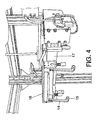
- Figure 4 shows the unloading/turning device, whose structure is similar to that of the manipulator arm (8), that is to say, equipped with pincers (14) completed with a pair of wheels (15), so that it can gently secure the tinplate sheets, these pincers also being operated by a pneumatic cylinder and able to move around the three axes of a system of rectangular coordinates, with the further particularity in this case that the body base (16) of the turning over device is mounted on a transversal axis (17), which enables it to turn over so that it can change the orientation of the treated surface of the sheet, as previously mentioned.
- Figure 5 shows the collection tray (18) where the different blocks or piles of tinplate sheets with different lithoprinting are to be stored, so that each one of them can subsequently be used when necessary.
- the manipulating device that the invention proposes has a series of advantages that basically focus on the following aspects:
Landscapes
- Engineering & Computer Science (AREA)
- Mechanical Engineering (AREA)
- Automation & Control Theory (AREA)
- Specific Conveyance Elements (AREA)
- Separation, Sorting, Adjustment, Or Bending Of Sheets To Be Conveyed (AREA)
Abstract
Description
- The invention relates to a manipulating device that has been especially designed to pick up tinplate sheets from a receiving table and place them either upon a turning device or upon a collecting tray, in order to prevent the treated surface from being damaged in any way during the handling process.
- The object of the invention is not only to prevent the tinplate sheets from being damaged, as mentioned above, but also to ensure that the transferral between the reception zone and the zone where they are deposited is carried out in a fully automated way.
- The invention can be applied not only in the process of manufacturing packaging for food products using tinplate sheets, but also, for example, for packaging for canned preserves, foodstuffs and similar.
- Metallic cans made from tinplate sheets are used to manufacture packaging that is used for certain types of food products or similar, and once these sheets have been duly punched out, formed and attached to each other, they form a sealed and airtight container. This treatment of the inner surface of the packaging is originally carried out on the tinplate sheets prior to the punching out process and manufacturing the packaging.
- As a result, in the manufacturing process of this type of packaging there is an initial stage that involves the manufacture of processed tinplate sheets, and a second stage at which there is a machine that manufactures the packaging from the aforementioned tinplate sheets.
- When transferring the sheets from one of the aforementioned operating stages to the other, there are two solutions, one of which is manual, in which one or several persons manually transfer the sheets from the cutting machines to the pallets where they are stored until use, or to a tray that supplies the machine that manufactures the packaging, both of these solutions giving rise to a considerable loss of time and the involvement of a work force, which adds the considerable risk of work accidents.
- The other solution, which is mechanical, uses machines that operate in a linear way, in such a way that a conveyor belt moves the sheets that have been cut by the cutting machine, from the latter to a lift that raises them so that a mechanical manipulator arm can collect them and send them to a tray that supplies the machine that manufactures the packaging. The problem is that said machine is invariably in a linear plane with the conveyor belt; furthermore, in the event of a decision being taken to store those sheets, the transport process to the pallets or the storage zone has to be carried out manually. Therefore, the entire handling process takes place with the treated surface of the sheets facing upwards, which is how the machine that manufactures the packaging has to receive them, which amounts to a permanent risk of the treated surface being scratched, thereby rendering it useless for being turned into a packaging, in such a way that if one wishes to overcome this problem, the cutting machine must supply the sheets with a treated surface that faces downwards, which means that it is necessary to turn it over manually immediately before it reaches the machine that manufactures the packaging.
- The manipulating device that is the object of the invention has been devised to overcome the aforementioned problem in a completely satisfactory way, thus permitting the entire process to be carried out in a fully automated way, not only when the tinplate sheets are arranged on a pallet or on a storage tray, but also when they are arranged on a supply tower on the machine that makes the packaging, making it possible for the entire sheet manipulation process to be carried out with the treated surface facing downwards, because the sheet is automatically turned over immediately before it is supplied to the above-mentioned machine.
- With a view to this and more specifically, it is proposed that the manipulating device that the invention proposes be provided with a receiving table, upon which the sheets that are supplied are placed by the cutting machine with the treated surface facing downwards, this receiving table being equipped with several channels whose number and width can be adjusted, so that they can receive the different types or sizes of sheet, with a loading zone where those sheets are placed as they are cut by the cutting machine, either directly by that machine and with the help of a worker, controlling the amount of sheet that is laid on each channel with the aid of a piling height detector, which controls a lift that raises the pile, which is moved to the opposite side of the receiving table, where the pile is then lowered so it can be placed on a support, these supports correspond to different channels on the receiving table, alternately adopting different heights, so that the blocks or packs of sheets are also arranged in a staggered formation, which makes it easier for them to be gripped for the next manipulation.
- A manipulator arm moves the sheets from the receiving table either to the unloading zone of the machine that makes the packaging, or to a collection tray or pallet.
- This manipulator arm is equipped with a claw with pincers and wheels lined with rubber, adaptable pincers whose width can be adjusted to cope with different sheet formats, the pincers being aided by adjustable clamping devices that sandwich the tinplate sheets as soon as the pincers have closed, by means of a pneumatic cylinder, and the above-mentioned manipulator arm can be moved in the direction of the axes of a system of rectangular coordinates, while also being able to rotate at the same time.
- The unloading zone is equipped with a turning device, composed of a claw that is very similar to the one on the manipulator arm, but in this case it is mounted between two points on an axis that enables a rotation actuator to carry out the turning over action. In view of the fact that this claw can operate on the supply tower belonging to the machine that makes the packages during this overturning process, the claw has been designed in such a way that it carries out a raising movement beforehand, so that it can find a zone that is free of obstruction and perform the turning over action, before descending towards the desired unloading position.
- Finally, the manipulating device is equipped with a collection tray, which enables it to store blocks of tinplate sheets with different lithoprinting, with as many possibilities as there are channels on the receiving table, this collection tray being assisted by a pneumatic cylinder that enable the tinplate sheets to be moved outside, so they can eventually be removed by a person.
- A set of drawings that is merely illustrative and in no way limiting has been enclosed to supplement the description that is being given, and these drawings have been included to help to make it easier to understand the characteristics of the invention, in accordance with a preferred embodiment thereof. The set of drawings comprises the following figures:
-
Figure 1 .- This is a perspective detail view of the receiving table that forms part of the manipulating device for lithoprinted tinplate sheets that is the object of this invention. -
Figure 2 .- This shows another detail perspective view, this time a partial view, of the same receiving table, specifically the part where the blocks of tinplate sheets are subjected to the actions of the manipulator arm. -
Figure 3 .- This figure also shows in a perspective view the manipulator arm that is used to extract the tinplate sheets from the receiving table. -
Figure 4 .- This figure also shows a perspective view similar to the one infigure 3 , but of the unloading/turning over device. -
Figure 5 .- This final figure shows a perspective close-up of the collection tray. - As has just been stated,
Figures 1 and2 show the receiving table, where there is a loading zone (1) and an unloading zone (2), set side by side. A series of channels (3), (3') and (3") are arranged on the loading zone (1), their purpose being to receive piles of tinplate sheets, each channel being formed by a pair of parallel strips, the distance between these strips being adjustable, so that they can adapt to the different sheet sizes. - The number of sheets that are positioned on each channel (3) is controlled by a pile detector (4), in such a way that when the maximum number is reached, the channels (3) are raised by means of a pneumatic cylinder (5), and another pneumatic cylinder (6) moves the tinplate sheets to the zone (2), where they are placed on a series of supports (7), (7'), (7"), etc., the number of these being the same as the number of channels (3) that are established in the loading zone (1) and their positions coinciding, but with the peculiarity that these supports (7) are at different heights, as can be seen perfectly in
Figure 2 , forming a staggered arrangement for the different piles of tinplate sheets lying on them, which makes it easy for the manipulator arm shown inFigure 3 to grip these blocks of sheets. - The aforementioned manipulator arm (8), suspended from the structure (9) of the manipulating device on a position that is considerably raised with respect to the receiving table (1 - 2), is a kind of claw equipped with pincers (10), completed with a pair of wheels (11) lined with rubber so that they do not damage the tinplate sheets during the manipulation process, the width of the pincers (10) being adjustable by means of a guiding and interlocking system so they can be adapted to the different tinplate sheet formats.
- Adjustable clamping devices (12) work in conjunction with the pincers (10) and, as has already been pointed out, these sandwich the tinplate sheets as soon as the pincers (10) have closed, by means of a pneumatic cylinder.
- As has also already been pointed out, this manipulator arm (8) can be moved vertically, transversally and lengthways, that is to say in accordance with the three axes of a system of rectangular coordinates, so that they can reach any point of the receiving table (1 - 2), and the aforementioned manipulator arm (8) is also able to revolve around itself so that the pincers can face any direction.
-
Figure 4 shows the unloading/turning device, whose structure is similar to that of the manipulator arm (8), that is to say, equipped with pincers (14) completed with a pair of wheels (15), so that it can gently secure the tinplate sheets, these pincers also being operated by a pneumatic cylinder and able to move around the three axes of a system of rectangular coordinates, with the further particularity in this case that the body base (16) of the turning over device is mounted on a transversal axis (17), which enables it to turn over so that it can change the orientation of the treated surface of the sheet, as previously mentioned. - Finally,
Figure 5 shows the collection tray (18) where the different blocks or piles of tinplate sheets with different lithoprinting are to be stored, so that each one of them can subsequently be used when necessary. - In accordance with the structure described, the manipulating device that the invention proposes has a series of advantages that basically focus on the following aspects:
- Manual handling is reduced to a minimum throughout the entire process, both at the beginning and at the end, which serves to prevent accidents and waste of unnecessary time, meaning that the process is uninterrupted.
- The manipulating device does not operate in a linear way, but moves on four axes, including the rotating axis.
- It offers the possibility of using different models of rolled metallic sheets and once the machine has been programmed, it can supply, at any time, the format for the packaging to be manufactured, because the machine has several working heads or working channels that can be classified directly from the cutting machine.
- The process of turning over the sheets makes it possible to ensure that they are correctly inserted into the machine that manufactures the packaging, and is also a process that does not involve manual handling.
- The tinplate sheets are turned over during the course of the normal process of the manipulator device, without there being any need for stoppages that would otherwise interrupt the process.
Claims (5)
- st.- A device for manipulating treated tinplate sheets, of the type that is used for manufacturing packaging for food products or similar, which have one surface suitably treated to prevent oxidation of the inside of the packaging, the purpose of this manipulating device being to create a direct link between the sheet cutting machine and the machine that makes the packaging, or with a storage zone for the sheets once they have been cut and before the said packaging machine, which is characterised by the fact that a receiving table (1-2) takes part in this process, which is equipped with the means for piling the tinplate sheets in different formats, means for controlling the size of the piles and means for supplying the different piles of tinplate sheets, a manipulator arm (8) working in collaboration with the receiving table, this manipulator arm being provided with a claw that can move like the axes of a system of rectangular coordinates, aided by an unloading/turning device (16), similar to the manipulator arm (8) but also able to carry out an overturning action that inverts the position of the sheets when they are being supplied to the machine that makes the packaging, a collection tray (18) also assisting the manipulating device as it is equipped with zones for piling the tinplate sheets in different formats, like those received by the receiving table (1 - 2).
- nd.- A device for manipulating treated tinplate sheets, as in the 1st Claim, characterised by the fact that the receiving table is equipped with a loading zone (1) and an exit zone (2), a series of channels (3), (3'), (3 "), etc. being established in the former, which can be adjusted in both number and width, whose purpose is to receive the different types of formats of cut sheets, these channels (3) being assisted by a raising cylinder (5) and a cylinder that moves transversally (6), which moves the sheets to the exit zone (2), where they are placed on a series of supports (7), (7'), (7"), etc., with the particularity that these supports (7), which can also be adjusted in both number and width, alternate with different heights giving the piles of sheets a staggered formation, so that it is easier for the manipulator arm (8) to grip them.
- rd.- A device for manipulating treated tinplate sheets, as in the previous claims, characterised by the fact that the loading zone (1) of the receiving table is equipped with a height detector (4) that establishes when the pile of tinplate sheets on any of the channels (3), (3'), (3"), etc. reaches the predetermined level after which it is moved to the exit zone (2).
- th.- A device for manipulating treated tinplate sheets, as in the 1st Claim, characterised by the fact that the manipulator arm (8) is equipped with swinging pincers (10), whose width can be modified so that they adapt to the different sheet formats, and completed with wheels (11) lined with rubber so that they do not damage the tinplate sheets when being handled, said pincers (10) aided by adjustable clamping devices (12) that, as soon as the pincers close, sandwich the tinplate sheets with the aid of a pneumatic cylinder (13).
- th.- A device for manipulating treated tinplate sheets, as in the 1st and 4th Claims, characterised by the fact that the structure of the unloading/turning device (16) is similar to the structure of the manipulator arm (8), the former also being equipped with pincers (14) and can be moved in the direction of the axes of a system of rectangular coordinates, with the peculiarity that it is also provided with a transversal axis (17) that enables the unloading device to turn over itself, at an angle of 180° to invert the position of the treated surface of the tinplate sheets immediately before they are supplied to the machine that makes the packages.
Applications Claiming Priority (2)
| Application Number | Priority Date | Filing Date | Title |
|---|---|---|---|
| ES200502078A ES2268989B1 (en) | 2005-08-22 | 2005-08-22 | HANDLER FOR TREATED SHEET SHEETS. |
| PCT/ES2005/000651 WO2007023195A2 (en) | 2005-08-22 | 2005-11-30 | Device for manipulating treated tinplate sheets |
Publications (1)
| Publication Number | Publication Date |
|---|---|
| EP1949983A2 true EP1949983A2 (en) | 2008-07-30 |
Family
ID=37771971
Family Applications (1)
| Application Number | Title | Priority Date | Filing Date |
|---|---|---|---|
| EP05824287A Withdrawn EP1949983A2 (en) | 2005-08-22 | 2005-11-30 | Device for manipulating treated tinplate sheets |
Country Status (3)
| Country | Link |
|---|---|
| EP (1) | EP1949983A2 (en) |
| ES (1) | ES2268989B1 (en) |
| WO (1) | WO2007023195A2 (en) |
Families Citing this family (1)
| Publication number | Priority date | Publication date | Assignee | Title |
|---|---|---|---|---|
| CN103537580B (en) * | 2013-11-05 | 2015-09-02 | 奥美森智能装备股份有限公司 | A kind of workbench of radiating fin material-gathering device |
Family Cites Families (5)
| Publication number | Priority date | Publication date | Assignee | Title |
|---|---|---|---|---|
| IT8354029V0 (en) * | 1983-12-12 | 1983-12-12 | Comau Spa | MANIPULATOR ROBOT PARTICULARLY FOR THE TRANSFER OF SHEET ELEMENTS FROM A MOLDING STATION TO THE NEXT STATION OF A MOLDING LINE |
| FR2661342A1 (en) * | 1990-04-27 | 1991-10-31 | Lectra Systemes Sa | Method and device for loading and unloading a cutting apparatus |
| JPH0773765B2 (en) * | 1990-06-05 | 1995-08-09 | 株式会社アマダ | Multi-collecting small product sorting / collecting device |
| US6179549B1 (en) * | 1997-11-21 | 2001-01-30 | Amada Metrecs Company, Ltd. | Loading and unloading device for sheet metals |
| US6481261B1 (en) * | 1999-05-01 | 2002-11-19 | Meltog Limited | Feed mechanism |
-
2005
- 2005-08-22 ES ES200502078A patent/ES2268989B1/en not_active Expired - Fee Related
- 2005-11-30 EP EP05824287A patent/EP1949983A2/en not_active Withdrawn
- 2005-11-30 WO PCT/ES2005/000651 patent/WO2007023195A2/en active Application Filing
Non-Patent Citations (1)
| Title |
|---|
| See references of WO2007023195A3 * |
Also Published As
| Publication number | Publication date |
|---|---|
| ES2268989A1 (en) | 2007-03-16 |
| ES2268989B1 (en) | 2008-12-16 |
| WO2007023195A3 (en) | 2008-06-19 |
| WO2007023195A2 (en) | 2007-03-01 |
Similar Documents
| Publication | Publication Date | Title |
|---|---|---|
| US11845620B2 (en) | Tool and method for layer depalletizing | |
| CN109110511B (en) | Automatic tray unstacking and stacking mechanism and automatic unstacking and stacking method | |
| EP2861361B1 (en) | Blanking line and method for stacking blanks outputted from a blanking shear or press | |
| CN107810155B (en) | Apparatus and method for loading storage area | |
| US6652217B2 (en) | System and method for separating double blanks | |
| EP2399850A1 (en) | Stacking line system and method | |
| EP3965997B1 (en) | Sorting system for a machine tool, machine tool and method for sorting cut parts | |
| JP2551295B2 (en) | Automatic cardboard box opening, article removal, folding method and device | |
| EP1949983A2 (en) | Device for manipulating treated tinplate sheets | |
| EP2499051B1 (en) | A machine for depalletising a multi-layer load | |
| EP3464139B1 (en) | Pile sheet remover | |
| JP2541424B2 (en) | Case automatic opening box, article removal, folding device | |
| US20080199289A1 (en) | Method and Device For Emptying Containers | |
| WO1993011043A1 (en) | Equipment for the automatic cutting of the wrapping film and subsequent depalletization of empty plastic or glass bottles or phials prior to their filling | |
| EP3822183A1 (en) | Automated hard drive static-shielding bag opening and removal | |
| CN211870709U (en) | Feeding and discharging structure and system | |
| CN211812084U (en) | Full-automatic dehydrogenation production equipment | |
| CN213059251U (en) | Stacking device | |
| US20240308715A1 (en) | Automated decanting apparatus, a system including the apparatus, and a method of automatic decanting using a programmable mechanical device | |
| CN220412093U (en) | Robot steel plate conveying workstation | |
| EP4375222A1 (en) | Depalletising system and method | |
| EP3501996B1 (en) | Capping machine with double tubular film handling system | |
| WO2017207485A1 (en) | Pile preparation unit with pile turner | |
| KR102479317B1 (en) | Discharge device for rimming moulding plastic container | |
| EP2607276B1 (en) | Apparatus and method for feeding paper blanks and similar flat objects |
Legal Events
| Date | Code | Title | Description |
|---|---|---|---|
| PUAI | Public reference made under article 153(3) epc to a published international application that has entered the european phase |
Free format text: ORIGINAL CODE: 0009012 |
|
| 17P | Request for examination filed |
Effective date: 20070704 |
|
| AK | Designated contracting states |
Kind code of ref document: A2 Designated state(s): AT BE BG CH CY CZ DE DK EE ES FI FR GB GR HU IE IS IT LI LT LU LV MC NL PL PT RO SE SI SK TR |
|
| AX | Request for extension of the european patent |
Extension state: AL BA HR MK YU |
|
| GRAP | Despatch of communication of intention to grant a patent |
Free format text: ORIGINAL CODE: EPIDOSNIGR1 |
|
| DAX | Request for extension of the european patent (deleted) | ||
| RIN1 | Information on inventor provided before grant (corrected) |
Inventor name: MARTIN GARCIA, ESTEBAN |
|
| STAA | Information on the status of an ep patent application or granted ep patent |
Free format text: STATUS: THE APPLICATION IS DEEMED TO BE WITHDRAWN |
|
| 18D | Application deemed to be withdrawn |
Effective date: 20100511 |