EP1949846A1 - System and method for the removal of undesired wavelengths from light - Google Patents
System and method for the removal of undesired wavelengths from light Download PDFInfo
- Publication number
- EP1949846A1 EP1949846A1 EP08100713A EP08100713A EP1949846A1 EP 1949846 A1 EP1949846 A1 EP 1949846A1 EP 08100713 A EP08100713 A EP 08100713A EP 08100713 A EP08100713 A EP 08100713A EP 1949846 A1 EP1949846 A1 EP 1949846A1
- Authority
- EP
- European Patent Office
- Prior art keywords
- light
- mirror
- wavelengths
- coating
- operable
- Prior art date
- Legal status (The legal status is an assumption and is not a legal conclusion. Google has not performed a legal analysis and makes no representation as to the accuracy of the status listed.)
- Withdrawn
Links
- 238000000034 method Methods 0.000 title claims abstract description 34
- 230000003287 optical effect Effects 0.000 claims abstract description 43
- 238000005286 illumination Methods 0.000 claims abstract description 23
- 238000001914 filtration Methods 0.000 claims abstract description 6
- 238000000576 coating method Methods 0.000 claims description 61
- 239000011248 coating agent Substances 0.000 claims description 44
- 230000005855 radiation Effects 0.000 claims description 19
- 238000001356 surgical procedure Methods 0.000 description 9
- 238000001429 visible spectrum Methods 0.000 description 8
- 239000000835 fiber Substances 0.000 description 7
- 208000002177 Cataract Diseases 0.000 description 5
- 230000004075 alteration Effects 0.000 description 4
- 230000005540 biological transmission Effects 0.000 description 4
- 231100000040 eye damage Toxicity 0.000 description 4
- 239000011521 glass Substances 0.000 description 4
- 239000000463 material Substances 0.000 description 4
- 239000000758 substrate Substances 0.000 description 4
- 230000008901 benefit Effects 0.000 description 3
- 230000000694 effects Effects 0.000 description 3
- 238000007792 addition Methods 0.000 description 2
- 230000002411 adverse Effects 0.000 description 2
- 230000003247 decreasing effect Effects 0.000 description 2
- 230000004048 modification Effects 0.000 description 2
- 238000012986 modification Methods 0.000 description 2
- 230000008707 rearrangement Effects 0.000 description 2
- 230000009467 reduction Effects 0.000 description 2
- 238000001228 spectrum Methods 0.000 description 2
- 238000006467 substitution reaction Methods 0.000 description 2
- 238000011144 upstream manufacturing Methods 0.000 description 2
- 201000004569 Blindness Diseases 0.000 description 1
- CBENFWSGALASAD-UHFFFAOYSA-N Ozone Chemical compound [O-][O+]=O CBENFWSGALASAD-UHFFFAOYSA-N 0.000 description 1
- 239000003855 balanced salt solution Substances 0.000 description 1
- 230000015556 catabolic process Effects 0.000 description 1
- 230000015271 coagulation Effects 0.000 description 1
- 238000005345 coagulation Methods 0.000 description 1
- 238000005336 cracking Methods 0.000 description 1
- 238000006731 degradation reaction Methods 0.000 description 1
- 230000006866 deterioration Effects 0.000 description 1
- 239000012530 fluid Substances 0.000 description 1
- 238000010438 heat treatment Methods 0.000 description 1
- 238000003384 imaging method Methods 0.000 description 1
- 238000002329 infrared spectrum Methods 0.000 description 1
- 230000002262 irrigation Effects 0.000 description 1
- 238000003973 irrigation Methods 0.000 description 1
- 208000018769 loss of vision Diseases 0.000 description 1
- 231100000864 loss of vision Toxicity 0.000 description 1
- 238000007726 management method Methods 0.000 description 1
- 239000013307 optical fiber Substances 0.000 description 1
- 230000035939 shock Effects 0.000 description 1
- 238000002834 transmittance Methods 0.000 description 1
- 238000002211 ultraviolet spectrum Methods 0.000 description 1
- 230000004393 visual impairment Effects 0.000 description 1
- 229910052724 xenon Inorganic materials 0.000 description 1
- FHNFHKCVQCLJFQ-UHFFFAOYSA-N xenon atom Chemical compound [Xe] FHNFHKCVQCLJFQ-UHFFFAOYSA-N 0.000 description 1
Images


Classifications
-
- G—PHYSICS
- G02—OPTICS
- G02B—OPTICAL ELEMENTS, SYSTEMS OR APPARATUS
- G02B27/00—Optical systems or apparatus not provided for by any of the groups G02B1/00 - G02B26/00, G02B30/00
- G02B27/10—Beam splitting or combining systems
- G02B27/1006—Beam splitting or combining systems for splitting or combining different wavelengths
-
- A—HUMAN NECESSITIES
- A61—MEDICAL OR VETERINARY SCIENCE; HYGIENE
- A61B—DIAGNOSIS; SURGERY; IDENTIFICATION
- A61B90/00—Instruments, implements or accessories specially adapted for surgery or diagnosis and not covered by any of the groups A61B1/00 - A61B50/00, e.g. for luxation treatment or for protecting wound edges
- A61B90/36—Image-producing devices or illumination devices not otherwise provided for
-
- G—PHYSICS
- G02—OPTICS
- G02B—OPTICAL ELEMENTS, SYSTEMS OR APPARATUS
- G02B27/00—Optical systems or apparatus not provided for by any of the groups G02B1/00 - G02B26/00, G02B30/00
- G02B27/10—Beam splitting or combining systems
- G02B27/14—Beam splitting or combining systems operating by reflection only
- G02B27/143—Beam splitting or combining systems operating by reflection only using macroscopically faceted or segmented reflective surfaces
-
- G—PHYSICS
- G02—OPTICS
- G02B—OPTICAL ELEMENTS, SYSTEMS OR APPARATUS
- G02B27/00—Optical systems or apparatus not provided for by any of the groups G02B1/00 - G02B26/00, G02B30/00
- G02B27/10—Beam splitting or combining systems
- G02B27/14—Beam splitting or combining systems operating by reflection only
- G02B27/145—Beam splitting or combining systems operating by reflection only having sequential partially reflecting surfaces
-
- G—PHYSICS
- G02—OPTICS
- G02B—OPTICAL ELEMENTS, SYSTEMS OR APPARATUS
- G02B5/00—Optical elements other than lenses
- G02B5/20—Filters
- G02B5/28—Interference filters
- G02B5/285—Interference filters comprising deposited thin solid films
- G02B5/286—Interference filters comprising deposited thin solid films having four or fewer layers, e.g. for achieving a colour effect
-
- G—PHYSICS
- G02—OPTICS
- G02B—OPTICAL ELEMENTS, SYSTEMS OR APPARATUS
- G02B6/00—Light guides; Structural details of arrangements comprising light guides and other optical elements, e.g. couplings
- G02B6/0001—Light guides; Structural details of arrangements comprising light guides and other optical elements, e.g. couplings specially adapted for lighting devices or systems
- G02B6/0005—Light guides; Structural details of arrangements comprising light guides and other optical elements, e.g. couplings specially adapted for lighting devices or systems the light guides being of the fibre type
- G02B6/0006—Coupling light into the fibre
-
- A—HUMAN NECESSITIES
- A61—MEDICAL OR VETERINARY SCIENCE; HYGIENE
- A61B—DIAGNOSIS; SURGERY; IDENTIFICATION
- A61B90/00—Instruments, implements or accessories specially adapted for surgery or diagnosis and not covered by any of the groups A61B1/00 - A61B50/00, e.g. for luxation treatment or for protecting wound edges
- A61B90/30—Devices for illuminating a surgical field, the devices having an interrelation with other surgical devices or with a surgical procedure
-
- A—HUMAN NECESSITIES
- A61—MEDICAL OR VETERINARY SCIENCE; HYGIENE
- A61F—FILTERS IMPLANTABLE INTO BLOOD VESSELS; PROSTHESES; DEVICES PROVIDING PATENCY TO, OR PREVENTING COLLAPSING OF, TUBULAR STRUCTURES OF THE BODY, e.g. STENTS; ORTHOPAEDIC, NURSING OR CONTRACEPTIVE DEVICES; FOMENTATION; TREATMENT OR PROTECTION OF EYES OR EARS; BANDAGES, DRESSINGS OR ABSORBENT PADS; FIRST-AID KITS
- A61F9/00—Methods or devices for treatment of the eyes; Devices for putting in contact-lenses; Devices to correct squinting; Apparatus to guide the blind; Protective devices for the eyes, carried on the body or in the hand
- A61F9/007—Methods or devices for eye surgery
-
- G—PHYSICS
- G02—OPTICS
- G02B—OPTICAL ELEMENTS, SYSTEMS OR APPARATUS
- G02B5/00—Optical elements other than lenses
- G02B5/20—Filters
- G02B5/208—Filters for use with infrared or ultraviolet radiation, e.g. for separating visible light from infrared and/or ultraviolet radiation
Definitions
- the present invention relates to sources of illumination. More particularly, embodiments of the present invention relate to the removal of undesired wavelengths from light. Even more particularly, embodiments of the present invention relate to systems and methods for removing undesired wavelengths from light using mirrors.
- the human eye can suffer a number of maladies causing mild deterioration to complete loss of vision. While contact lenses and eyeglasses can compensate for some ailments, ophthalmic surgery is required for others. Generally, ophthalmic surgery is classified into posterior segment procedures, such as vitreoretinal surgery, and anterior segment procedures, such as cataract surgery. More recently, combined anterior and posterior segment procedures have been developed.
- the surgical instrumentation used for ophthalmic surgery can be specialized for anterior segment procedures or posterior segment procedures or support both.
- Such surgical instrumentation can comprise a Vitreoretinal and Cataract microsurgical console.
- a surgical console can provide a variety of functions depending on the surgical procedure and surgical instrumentation. For example, surgical consoles can expedite cataract surgeries (e.g. phacoemulsification procedures) by helping manage irrigation and aspiration flows into and out of a surgical site. Surgical consoles can also provide other functions, as will be known to those having skill in the art.
- microsurgical consoles typically provide a source of illumination, such that the source of illumination can be used to illuminate the area on which a procedure is being performed.
- These illuminators provide visible light from a light source through, for example, an optic fiber or the like.
- the light source may generate wavelengths of light which are not useful for illumination (e.g., those other than visible light), such as ultraviolet (UV) or infrared (IR) light. These wavelengths may adversely affect the surgical system by, for example, causing a reduction in the lifetime of lamp electrodes, thermal and UV damage to the system optical components over time, decreased optical performance due to spherical and chromatic aberrations, beam steering, etc. More specifically, the illuminator bulb electrodes, due to absorbing this undesired radiation, will erode more quickly, the optics of the system may heat up significantly leading to reliability issues (i.e.
- UV ultraviolet
- IR infrared
- Embodiments of the present invention provide an illumination system and method that can be utilized in conjunction with a surgical console and which are substantially safer, more durable and less expensive to operate than prior art systems and methods for providing illumination.
- One embodiment of the present invention includes a method for providing light to a source of illumination. The method can comprise the steps of: providing light from a light source wherein the light has two components, one component reflected from a mirror having a coating operable to reflect desired wavelengths of light and transmit undesired wavelengths and a second component provided directly from the light source (e.g. not reflected off the mirror).
- Other embodiments may provide other mirrors to further reduce the undesired wavelengths in the light provided through the source of illumination.
- an additional coated mirror may be provided such that the light (e.g. both components) may be filtered using this mirror.
- One of these mirrors may be a hot mirror coated to reflect the desired wavelengths and transmit the undesired wavelengths.
- embodiments of the present invention provide the advantage that the lifetime and reliability of components within the optical path of an illuminator may be extended by reducing the amount of radiation absorbed by components within the optical path while simultaneously improving the performance of the illuminator by reducing spherical and chromatic aberrations.
- the safety of illumination systems incorporating an embodiment of the present invention especially in a surgical context, may be greatly improved.
- FIGURES Preferred embodiments of the invention are illustrated in the FIGURES, like numerals being used to refer to like and corresponding parts of the various drawings.
- Vitreoretinal and Cataract microsurgical consoles can provide an illuminator.
- These illuminators provide visible light from a light source through, for example, an optic fiber or the like, and may be used to illuminate an area on which a procedure is being performed.
- the light source for these illuminators may generate wavelengths of light which are not useful for illumination (e.g., those other than visible light), such as ultraviolet (UV) or infrared (IR) light, or which may cause aphakic hazard weighted irradiance, such as certain wavelengths of blue light.
- UV ultraviolet
- IR infrared
- Embodiments of the present invention solve this problem by using one or more mirrors in the optical path of an illuminator.
- one or more cold mirrors in the optical path are coated such that they are operable to reflect light in the desired wavelengths (e.g. visible wavelengths), while transmitting other wavelengths of light (e.g. IR, UV or selected wavelengths of blue light).
- desired wavelengths e.g. visible wavelengths
- other wavelengths of light e.g. IR, UV or selected wavelengths of blue light.
- one or more hot mirrors mirror may also be provided in the optical path, wherein these hot mirrors are coated such that they are operable to transmit the desired wavelengths of light and reflect or absorb undesired wavelengths.
- additional undesired wavelengths may be removed from the light (relative to utilizing no mirrors, or cold mirrors alone) before the light is used to illuminate an area.
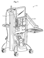
- FIGURE 1 is a diagrammatic representation of one embodiment of an ophthalmic surgical console 100.
- Surgical console 100 can include a swivel monitor 110 that has a touch screen.
- Swivel monitor 110 can be positioned in a variety of orientations for whoever needs to see the touch screen. Swivel monitor 110 can swing from side to side, as well as rotate and tilt.
- the touch screen may provide a graphical user interface ("GUI") that allows a user to interact with console 100.
- GUI graphical user interface
- Surgical console 100 also includes a connection panel used to connect various tools and consumables to surgical console 100.
- the connection panel can include, for example, a coagulation connector, balanced salt solution receiver, connectors for various hand pieces and a fluid management system ("FMS") or cassette receiver.
- Surgical console 100 can also include a variety of user friendly features, such as a foot pedal control (e.g., stored behind a panel of the console) and other features.
- a foot pedal control e.g., stored behind a panel of the console
- One of these features may be one or more illuminators 200 to provide visible (or other wavelengths) of light to an area undergoing examination or surgical procedure.
- Surgical console 100 is provided by way of example and embodiments of the present invention can be implemented with a variety of surgical systems.
- Example surgical systems in which various embodiments of the present invention can be used include, for example, the Constellation® Surgical Console, Series 2000® Legacy® cataract surgical system, the Accurus® 400VS surgical system, and the InfinitiTM Vision System surgical system available from Alcon Laboratories Inc. of Fort Worth, Texas. While embodiments of the invention may be discussed with reference to such surgical consoles, it will be apparent that embodiments of the present invention can be implemented in other suitable surgical systems or, in general, in any system where it may be desirable to provide illumination.
- FIGURE 2 shows in more detail an embodiment of an illuminator 200.
- illuminator 200 is a two port illuminator, having two ports 210a and 210b where light from light source 220 is focused onto the proximal end of an illumination delivery device (source of illumination), such as optic fiber 212, for delivery to its eventual destination (e.g. a location at the distal end of optic fiber 212).
- source of illumination such as optic fiber 212
- optical path corresponding to port 210a light from light source 220 reflected from spherical mirror 230a and light directly (meaning, in this case, that this light has not been reflected from spherical mirror 230a) from light source 220 is passed through collimating lens 240a, after which the light is reflected from cold mirror 250a (which may be at an angle of approximately 22.5 degrees), transmitted through hot mirror 260a and passed through attenuator 270a before being condensed onto optic fiber 212a by condensing lens 280a.
- the optical path corresponding to port 210b is substantially similar to that described with respect to port 210a and descriptions applicable to the optical path corresponding to port 210a may, in this particular embodiment, be similarly applied to the optical path corresponding to port 210b.
- light from light source 220 is filtered by selecting appropriate glass material or optical coatings for components for one or more components within the optical path of the light from light source 220 such that undesired wavelengths are removed from the light before it is condensed onto optic fiber 212.
- specific coatings may be placed on one or more components within the optical path based upon the component's position or function within the optical path.
- Dichroic coatings are an effective way of separating light in one wavelength band from light in another band by transmitting one wavelength and reflecting another.
- These dichroic coatings may comprise multiple layers of one or more materials chosen based on their material properties (e.g. refractive indices) and the properties of the substrate material (e.g. glass).
- the thickness or order in which these coatings are deposited on the optical component may be varied in order to achieve an effect on the transmittance or reflectance of the optical component.
- a dichroic coating operable to remove IR and UV may be applied to one or more reflective optics within the optical path of an illuminator while an absorptive/dichroic coating may be applied to the transmittive optics within the optical path.
- spherical mirror 230 and cold mirror 250 may comprise a glass substrate coated with a dichroic coating operable to transmit or absorb IR and UV wavelengths of light while reflecting visible wavelengths of light (though each of spherical mirrors 230 and cold mirror 250 may comprise different or unique substrates and coatings), while hot mirror 260 may have a glass substrate coated with a dichroic/absorptive coating to reflect or absorb UV and IR wavelengths and transmit visible wavelengths.
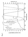
- line 300 represents the spectra of light source 220, which in one embodiment may be a substantially ozone free Xenon short arc lamp such as that made by Osram. Notice that this light source has significant emissions outside the spectrum of visible wavelengths (400-700nm).
- Line 310 represents the transmittive performance of the coating applied to both spherical mirror 230 and cold mirror 250, while line 320 represents the transmittive performance of the coating of hot mirror 260.
- FIGURE 4 depicts the properties of the embodiments of the respective coatings on a greater scale.
- the coating applied to spherical mirror 230 and cold mirror 250 results in the effective transmission of wavelengths of light substantially outside the visible spectrum while the coating applied to hot mirror 260 (represented by line 320) results in the transmission of light substantially within the visible spectrum.
- spherical mirror 230a may be coated with a dichroic coating operable to transmit (or absorb) IR and UV wavelengths of light while reflecting visible wavelengths of light as mentioned above, the light may be filtered using spherical mirror 230a, and thus light reflected from spherical mirror 230a may comprise light substantially within the visible wavelengths while out of band or undesired wavelengths (e.g.
- light not within the visible wavelengths may be absorbed or collected in out-of-band radiation dump 232a.
- light passing through collimating lens 240a may comprise a first component of light reflected from spherical mirror 230a from which wavelengths of light outside of the visible spectrum have been substantially removed (e.g. filtered) and a second component of light directly from light source 220 which still comprises wavelengths outside the visible spectrum. After passing through collimating lens 240a, then, the light is reflected from cold mirror 250a.
- cold mirror 250a may similarly be coated with a dichroic coating operable to transmit (or absorb) IR and UV wavelengths of light while reflecting visible wavelengths of light, the light may be filtered using cold mirror 250a and light reflected from cold mirror 250a may comprise light substantially within the visible wavelengths while remaining out of band wavelengths may be absorbed or collected in out of band radiation dump 252a. The light reflected from cold mirror 250a may then be passed through hot mirror 260a, which is coated with a dichroic/absorptive coating operable to reflect (or absorb) UV and IR wavelengths and transmit visible wavelengths.
- hot mirror 260a may additionally be tuned to meet any desired aphakic properties of illuminator 200.
- the use of a dichroic spherical mirror may prevent undesired wavelengths from re-imaging onto the bulb electrodes and decrease the amount of out-of band light that could be potentially absorbed into optical components in the optical path downstream.
- the operating temperature of any hot mirrors within the optical path may be reduced, reducing the likelihood of component failure or degradation.
- the amount of radiation absorbed by other components within the system may be reduced, reducing the heating or other stresses placed on these components.
- various specifications e.g., hazard specifications or the like
Landscapes
- Physics & Mathematics (AREA)
- General Physics & Mathematics (AREA)
- Optics & Photonics (AREA)
- Health & Medical Sciences (AREA)
- Surgery (AREA)
- Life Sciences & Earth Sciences (AREA)
- Nuclear Medicine, Radiotherapy & Molecular Imaging (AREA)
- Pathology (AREA)
- Oral & Maxillofacial Surgery (AREA)
- Engineering & Computer Science (AREA)
- Biomedical Technology (AREA)
- Heart & Thoracic Surgery (AREA)
- Medical Informatics (AREA)
- Molecular Biology (AREA)
- Animal Behavior & Ethology (AREA)
- General Health & Medical Sciences (AREA)
- Public Health (AREA)
- Veterinary Medicine (AREA)
- Optical Filters (AREA)
Abstract
Description
- The present invention relates to sources of illumination. More particularly, embodiments of the present invention relate to the removal of undesired wavelengths from light. Even more particularly, embodiments of the present invention relate to systems and methods for removing undesired wavelengths from light using mirrors.
- The human eye can suffer a number of maladies causing mild deterioration to complete loss of vision. While contact lenses and eyeglasses can compensate for some ailments, ophthalmic surgery is required for others. Generally, ophthalmic surgery is classified into posterior segment procedures, such as vitreoretinal surgery, and anterior segment procedures, such as cataract surgery. More recently, combined anterior and posterior segment procedures have been developed.
- The surgical instrumentation used for ophthalmic surgery can be specialized for anterior segment procedures or posterior segment procedures or support both. Such surgical instrumentation can comprise a Vitreoretinal and Cataract microsurgical console. Such a surgical console can provide a variety of functions depending on the surgical procedure and surgical instrumentation. For example, surgical consoles can expedite cataract surgeries (e.g. phacoemulsification procedures) by helping manage irrigation and aspiration flows into and out of a surgical site. Surgical consoles can also provide other functions, as will be known to those having skill in the art.
- Clearly seeing an area upon which a surgical procedures is being performed is obviously important. Therefore, microsurgical consoles typically provide a source of illumination, such that the source of illumination can be used to illuminate the area on which a procedure is being performed. These illuminators provide visible light from a light source through, for example, an optic fiber or the like.
- In many cases, the light source may generate wavelengths of light which are not useful for illumination (e.g., those other than visible light), such as ultraviolet (UV) or infrared (IR) light. These wavelengths may adversely affect the surgical system by, for example, causing a reduction in the lifetime of lamp electrodes, thermal and UV damage to the system optical components over time, decreased optical performance due to spherical and chromatic aberrations, beam steering, etc. More specifically, the illuminator bulb electrodes, due to absorbing this undesired radiation, will erode more quickly, the optics of the system may heat up significantly leading to reliability issues (i.e. thermal shock and cracking) in the optics as well as their optical coatings, and thermal expansion can induce spherical and chromatic aberrations in the optics of the system, further reducing the performance of the system. This is an undesirable effect because damage to the surgical system optics or their optical coatings can lead to a dangerous amount of light passing through the optics and into the eye, resulting in eye damage. Furthermore, unwanted UV or IR radiation that reaches the eye can potentially cause eye damage.
- In past illuminators the problem of reducing out of band emissions was addressed by placing a band pass mirror (also called a "hot mirror") in the optical path to absorb or reflect undesired wavelengths of light. However, no specific hardware or methods were put in place to eliminate undesired radiation at the illuminator optical source or from the optical train upstream of the hot mirror. Thus, during the operation of these prior art systems the hot mirror and the optics upstream of the hot mirror continued to heat to unacceptable levels. Therefore, there is a need for a system and method that can effectively and efficiently reduce or eliminate undesired wavelengths in light provided by a light source.
- Embodiments of the present invention provide an illumination system and method that can be utilized in conjunction with a surgical console and which are substantially safer, more durable and less expensive to operate than prior art systems and methods for providing illumination. One embodiment of the present invention includes a method for providing light to a source of illumination. The method can comprise the steps of: providing light from a light source wherein the light has two components, one component reflected from a mirror having a coating operable to reflect desired wavelengths of light and transmit undesired wavelengths and a second component provided directly from the light source (e.g. not reflected off the mirror). Other embodiments may provide other mirrors to further reduce the undesired wavelengths in the light provided through the source of illumination. For example, an additional coated mirror may be provided such that the light (e.g. both components) may be filtered using this mirror. One of these mirrors may be a hot mirror coated to reflect the desired wavelengths and transmit the undesired wavelengths.
- By removing undesired wavelengths of light, such as those that fall outside the visible spectrum or certain wavelengths of blue-light, embodiments of the present invention provide the advantage that the lifetime and reliability of components within the optical path of an illuminator may be extended by reducing the amount of radiation absorbed by components within the optical path while simultaneously improving the performance of the illuminator by reducing spherical and chromatic aberrations. By reducing or eliminating such problems in the optical path, the safety of illumination systems incorporating an embodiment of the present invention, especially in a surgical context, may be greatly improved.
- These, and other, aspects of the invention will be better appreciated and understood when considered in conjunction with the following description and the accompanying drawings. The following description, while indicating various embodiments of the invention and numerous specific details thereof, is given by way of illustration and not of limitation. Many substitutions, modifications, additions or rearrangements may be made within the scope of the invention, and the invention includes all such substitutions, modifications, additions or rearrangements.
- A more complete understanding of the present invention and the advantages thereof may be acquired by referring to the following description, taken in conjunction with the accompanying drawings in which like reference numbers indicate like features and wherein:
-
FIGURE 1 is a diagrammatic representation of one embodiment of a surgical console in accordance with the embodiments of this invention; -
FIGURE 2 is a representation of one embodiment of an illuminator in accordance with the embodiments of this invention; -
FIGURE 3 is a graphical representation of the operational ability of embodiments of various coatings; and -
FIGURE 4 is a graphical representation of the operational ability of embodiments of various coatings in accordance with this invention. - Preferred embodiments of the invention are illustrated in the FIGURES, like numerals being used to refer to like and corresponding parts of the various drawings.
- Vitreoretinal and Cataract microsurgical consoles can provide an illuminator. These illuminators provide visible light from a light source through, for example, an optic fiber or the like, and may be used to illuminate an area on which a procedure is being performed. The light source for these illuminators may generate wavelengths of light which are not useful for illumination (e.g., those other than visible light), such as ultraviolet (UV) or infrared (IR) light, or which may cause aphakic hazard weighted irradiance, such as certain wavelengths of blue light. These extraneous wavelengths may adversely affect the surgical system, including causing a reduction in the lifetime of certain components, decreased performance due to spherical and chromatic aberrations or other causes, etc. Damage to the optics or their optical coatings in a surgical setting can allow a dangerous amount of light to pass into the eye, resulting in eye damage. Furthermore, unwanted UV or IR radiation or blue light that reaches the eye can potentially cause eye damage. Thus, it is desirable that an illuminator, whether in a surgical console or a stand-alone device, effectively reduce or eliminate undesired wavelengths in the light that it provides.
- Embodiments of the present invention solve this problem by using one or more mirrors in the optical path of an illuminator. In a preferred embodiment, one or more cold mirrors in the optical path are coated such that they are operable to reflect light in the desired wavelengths (e.g. visible wavelengths), while transmitting other wavelengths of light (e.g. IR, UV or selected wavelengths of blue light). Thus, as light from a light source is reflected off these cold mirrors, undesired wavelengths of light may be substantially removed from the light before it is utilized to illuminate an area. In other embodiments, one or more hot mirrors mirror may also be provided in the optical path, wherein these hot mirrors are coated such that they are operable to transmit the desired wavelengths of light and reflect or absorb undesired wavelengths. Thus, by transmitting the light through these hot mirrors additional undesired wavelengths may be removed from the light (relative to utilizing no mirrors, or cold mirrors alone) before the light is used to illuminate an area.
-
FIGURE 1 is a diagrammatic representation of one embodiment of an ophthalmicsurgical console 100.Surgical console 100 can include aswivel monitor 110 that has a touch screen. Swivelmonitor 110 can be positioned in a variety of orientations for whoever needs to see the touch screen. Swivelmonitor 110 can swing from side to side, as well as rotate and tilt. The touch screen may provide a graphical user interface ("GUI") that allows a user to interact withconsole 100. -
Surgical console 100 also includes a connection panel used to connect various tools and consumables tosurgical console 100. The connection panel can include, for example, a coagulation connector, balanced salt solution receiver, connectors for various hand pieces and a fluid management system ("FMS") or cassette receiver.Surgical console 100 can also include a variety of user friendly features, such as a foot pedal control (e.g., stored behind a panel of the console) and other features. One of these features may be one ormore illuminators 200 to provide visible (or other wavelengths) of light to an area undergoing examination or surgical procedure. -
Surgical console 100 is provided by way of example and embodiments of the present invention can be implemented with a variety of surgical systems. Example surgical systems in which various embodiments of the present invention can be used include, for example, the Constellation® Surgical Console, Series 2000® Legacy® cataract surgical system, the Accurus® 400VS surgical system, and the Infiniti™ Vision System surgical system available from Alcon Laboratories Inc. of Fort Worth, Texas. While embodiments of the invention may be discussed with reference to such surgical consoles, it will be apparent that embodiments of the present invention can be implemented in other suitable surgical systems or, in general, in any system where it may be desirable to provide illumination. - As discussed above,
surgical console 100 may provideilluminators 200.FIGURE 2 shows in more detail an embodiment of anilluminator 200. As shown inFIGURE 2 ,illuminator 200 is a two port illuminator, having twoports light source 220 is focused onto the proximal end of an illumination delivery device (source of illumination), such as optic fiber 212, for delivery to its eventual destination (e.g. a location at the distal end of optic fiber 212). More particularly, with respect to the optical path corresponding toport 210a, light fromlight source 220 reflected fromspherical mirror 230a and light directly (meaning, in this case, that this light has not been reflected fromspherical mirror 230a) fromlight source 220 is passed throughcollimating lens 240a, after which the light is reflected fromcold mirror 250a (which may be at an angle of approximately 22.5 degrees), transmitted throughhot mirror 260a and passed throughattenuator 270a before being condensed ontooptic fiber 212a by condensinglens 280a. Note that the optical path corresponding toport 210b is substantially similar to that described with respect toport 210a and descriptions applicable to the optical path corresponding to port 210a may, in this particular embodiment, be similarly applied to the optical path corresponding toport 210b. - As mentioned above, it may be desirable to remove undesired wavelengths from light delivered to
optic fiber 212a, especially those wavelengths of light that fall substantially within the UV and IR spectrums. To achieve this, in one embodiment of the invention, light fromlight source 220 is filtered by selecting appropriate glass material or optical coatings for components for one or more components within the optical path of the light fromlight source 220 such that undesired wavelengths are removed from the light before it is condensed onto optic fiber 212. - More specifically, in one embodiment, specific coatings may be placed on one or more components within the optical path based upon the component's position or function within the optical path. Dichroic coatings are an effective way of separating light in one wavelength band from light in another band by transmitting one wavelength and reflecting another. These dichroic coatings may comprise multiple layers of one or more materials chosen based on their material properties (e.g. refractive indices) and the properties of the substrate material (e.g. glass). The thickness or order in which these coatings are deposited on the optical component may be varied in order to achieve an effect on the transmittance or reflectance of the optical component. Thus, a dichroic coating operable to remove IR and UV may be applied to one or more reflective optics within the optical path of an illuminator while an absorptive/dichroic coating may be applied to the transmittive optics within the optical path.
- The use of such coatings may be better elucidated with reference to
illuminator 200 depicted inFIGURE 2 . In one embodiment, spherical mirror 230 and cold mirror 250 may comprise a glass substrate coated with a dichroic coating operable to transmit or absorb IR and UV wavelengths of light while reflecting visible wavelengths of light (though each of spherical mirrors 230 and cold mirror 250 may comprise different or unique substrates and coatings), while hot mirror 260 may have a glass substrate coated with a dichroic/absorptive coating to reflect or absorb UV and IR wavelengths and transmit visible wavelengths. - The respective properties of these coatings may be better understood with reference to the graphs of
FIGURES 3 and4 which depict the properties of embodiments of the respective coatings of the optical components within the optical path ofilluminator 200. With reference specifically toFIGURE 3 ,line 300 represents the spectra oflight source 220, which in one embodiment may be a substantially ozone free Xenon short arc lamp such as that made by Osram. Notice that this light source has significant emissions outside the spectrum of visible wavelengths (400-700nm).Line 310 represents the transmittive performance of the coating applied to both spherical mirror 230 and cold mirror 250, whileline 320 represents the transmittive performance of the coating of hot mirror 260. Notice that the coating applied to spherical mirror 230 and cold mirror 250 (represented by line 310) results in the effective transmission of wavelengths of light substantially outside the visible spectrum while the coating applied to hot mirror 260 (represented by line 320) results in the transmission of light substantially within the visible spectrum. - The efficacy of these respective coatings may be illustrated in more detail with reference to
FIGURE 4 which depicts the properties of the embodiments of the respective coatings on a greater scale. Again, notice how the coating applied to spherical mirror 230 and cold mirror 250 (represented by line 310) results in the effective transmission of wavelengths of light substantially outside the visible spectrum while the coating applied to hot mirror 260 (represented by line 320) results in the transmission of light substantially within the visible spectrum. - The effect of the various coated components within the optical path may be explained with reference back to
FIGURE 2 . Referring to the optical path corresponding withport 210a, light directly fromlight source 220 and light reflected fromspherical mirror 230a is passed throughcollimating lens 240a. However, asspherical mirror 230a may be coated with a dichroic coating operable to transmit (or absorb) IR and UV wavelengths of light while reflecting visible wavelengths of light as mentioned above, the light may be filtered usingspherical mirror 230a, and thus light reflected fromspherical mirror 230a may comprise light substantially within the visible wavelengths while out of band or undesired wavelengths (e.g. light not within the visible wavelengths) may be absorbed or collected in out-of-band radiation dump 232a. Thus, light passing throughcollimating lens 240a may comprise a first component of light reflected fromspherical mirror 230a from which wavelengths of light outside of the visible spectrum have been substantially removed (e.g. filtered) and a second component of light directly fromlight source 220 which still comprises wavelengths outside the visible spectrum. After passing throughcollimating lens 240a, then, the light is reflected fromcold mirror 250a. - As
cold mirror 250a may similarly be coated with a dichroic coating operable to transmit (or absorb) IR and UV wavelengths of light while reflecting visible wavelengths of light, the light may be filtered usingcold mirror 250a and light reflected fromcold mirror 250a may comprise light substantially within the visible wavelengths while remaining out of band wavelengths may be absorbed or collected in out ofband radiation dump 252a. The light reflected fromcold mirror 250a may then be passed throughhot mirror 260a, which is coated with a dichroic/absorptive coating operable to reflect (or absorb) UV and IR wavelengths and transmit visible wavelengths. Thus, by filtering the light usinghot mirror 260a, any residual wavelengths of light not within the visible spectrum are reflected byhot mirror 260a and absorbed or collected in out ofband radiation dump 252a while visible wavelengths are transmitted throughhot mirror 260a and attenuator 270 before being condensed ontooptical fiber 212a by condensinglens 280a. In one embodiment,hot mirror 260a may additionally be tuned to meet any desired aphakic properties ofilluminator 200. - Thus, by using various coated optical components within an optical path to remove undesired wavelengths of light a number of advantages may be achieved. Namely, the use of a dichroic spherical mirror may prevent undesired wavelengths from re-imaging onto the bulb electrodes and decrease the amount of out-of band light that could be potentially absorbed into optical components in the optical path downstream. By reducing the amount of out-of-band light at various points in the optical path the operating temperature of any hot mirrors within the optical path may be reduced, reducing the likelihood of component failure or degradation. Similarly, by absorbing undesired wavelengths of light transmitted or reflected by the various mirrors, the amount of radiation absorbed by other components within the system may be reduced, reducing the heating or other stresses placed on these components. Furthermore, by applying different coatings based upon the type of light source utilized in a particular embodiment of illuminator, various specifications (e.g., hazard specifications or the like) may be obtained.
- Although the present invention has been described in detail herein with reference to the illustrated embodiments, it should be understood that the description is by way of example only and is not to be construed in a limiting sense. It is to be further understood, therefore, that numerous changes in the details of the embodiment of this invention and additional embodiments of this invention will be apparent, and may be made by, persons of ordinary skill in the art having reference to this description. For example, thought embodiments of the invention have been described in conjunction with a two port illuminator having a spherical mirror, a cold mirror and a hot mirror it will be understood that embodiments of the present invention may apply equally well to illuminators with more or fewer ports or more or fewer spherical, cold or hot mirrors. It is contemplated that all such changes and additional embodiments are within scope of the invention as claimed below.
Claims (35)
- A method for removing undesired wavelengths of light, comprising:providing light from a light source (220) to a source of illumination (212), the light having a first component and a second component, the first component provided directly from the light source; andfiltering the second component of light with a first mirror (230), wherein the first mirror has a coating operable to reject light of undesired wavelengths.
- The method of claim 1, wherein the coating of the first mirror is operable to reflect light in desired wavelengths and transmit light of undesired wavelengths.
- The method of claim 2, wherein the first mirror (230) is a spherical mirror
- The method of claim 3, wherein the coating of the first mirror (230) is a dichroic coating.
- The method of claim 4, further comprising absorbing the undesired wavelengths of light transmitted by the first mirror (230) in a first radiation dump (232).
- The method of claim 1, further comprising filtering the light using a second mirror (250), wherein the second mirror has a coating operable to reject light of the undesired wavelengths.
- The method of claim 6, wherein the coating of the second mirror (250) is operable to reflect light in the desired wavelengths and transmit light of the undesired wavelengths.
- The method of claim 7, wherein the coating of the second mirror (250) is a dichroic coating.
- The method of claim 8, wherein the second mirror (250) is at an angle of approximately 22.5 degrees.
- The method of claim 9, further comprising absorbing the undesired wavelengths of light transmitted by the second mirror (250) in a second radiation dump (252).
- The method of claim 6, further comprising filtering the light with third mirror (260), the third mirror having a coating operable to reject light of the undesired wavelengths.
- The method of claim 11, wherein the coating of the third mirror (260) is operable to reflect light in the undesired wavelengths and transmit light in the desired wavelengths.
- The method of claim12, wherein the coating of the third mirror (260) is a dichroic and absorptive coating.
- The method of claim 13, further comprising absorbing the undesired wavelengths of light reflected by the third mirror (260) in the second radiation dump (252).
- The method of claim 11, further comprising passing the light reflected from the first mirror (230) through a collimating lens (240) before filtering the light with the second mirror (250).
- The method of claim 15, wherein the light is filtered with the second mirror (250) before it is filtered with the third mirror (260).
- The method of claim 16, further comprising condensing the light onto the source of illumination (212) using a condensing lens (280).
- A system, comprising:a light source (220);a first mirror (230) having a coating operable to reject light of undesired wavelengths; anda source of illumination (212), wherein source of illumination is operable to provide light from the light source, the light having a first component and a second component, the first component provided directly from the light source and the second component filtered with the first mirror.
- The system of claim 18, wherein the coating of the first mirror (230) is operable to reflect light in desired wavelengths and transmit light of undesired wavelengths.
- The system of claim 19, wherein the first mirror (230) is a spherical mirror.
- The system of claim 20, wherein the coating of the first mirror (230) is a dichroic coating.
- The system of claim 21, further comprising a first radiation dump (232) operable to absorb the undesired wavelengths of light transmitted by the first mirror (230).
- The system of claim 18, further comprising a second mirror (250) having a coating operable to reject light of the undesired wavelengths wherein the light is filtered using the second mirror.
- The system of claim 23, wherein the coating of the second mirror (250) is operable to reflect light in the desired wavelengths and transmit light of the undesired wavelengths wherein the light is filtered using the second mirror.
- The system of claim 24, wherein the coating of the second mirror (250) is a dichroic coating.
- The system of claim 25, wherein the second mirror (250) is at an angle of approximately 22.5 degrees.
- The system of claim 26, further comprising a second radiation dump (252) operable to absorb the undesired wavelengths of light transmitted by the second mirror (250).
- The system of claim 23, further comprising a third mirror (260) having a coating operable to reject light of the undesired wavelengths, wherein the light is filtered by the third mirror.
- The system of claim 28, wherein the coating of the third mirror (260) is operable to reflect light in the undesired wavelengths and transmit light in the desired wavelengths.
- The system of claim 29, wherein the coating of the third mirror (260) is a dichroic and absorptive coating.
- The system of claim 30, wherein the undesired wavelengths of light reflected by the third mirror (260) are absorbed in the second radiation dump (252).
- The system of claim 28, further comprising a collimating lens, wherein the light is passed through the collimating lens (240) before it is filtered with the second mirror (250).
- The system of claim 32, wherein the light is filtered with the second mirror (250) before it is filtered with the third mirror (260).
- The system of claim 33, further comprising a condensing lens (280) operable to condense the light onto the source of illumination (212).
- An illuminator, comprising:a light source (220);a first optical path, the first optical path, comprisinga first source of illumination (212a),a first mirror (230a) wherein the first mirror is spherical and has a coating operable to reflect light of visible wavelengths and transmit or absorb light of IR and UV wavelengths,a second mirror (250a) having a coating operable to reflect light of visible wavelengths and transmit or absorb light of IR and UV wavelengths,a third mirror (260a) having a coating operable to reflect or absorb light in the IR and UV wavelengths and transmit light of visible wavelengths, wherein the source of illumination is operable to provide light from the light source, the light having a first component and a second component, the first component provided directly from the light source and the second component filtered with the first spherical mirror before the light is filtered using the second mirror and the third mirror,a first radiation dump (232a) operable to absorb the light transmitted by the first spherical mirror, anda second radiation dump (252a) operable to absorb the light transmitted by the second mirror and reflected by the third mirror; anda second optical path, the second optical path, comprisinga second source of illumination (212b),a fourth mirror (230b) wherein the fourth mirror is spherical and has a coating operable to reflect light in the IR and UV wavelengths and transmit light of visible wavelengths,a fifth mirror (250b) having a coating operable to reflect light in the IR and UV wavelengths and transmit light of visible wavelengths,a sixth mirror (260b) having a coating operable to reflect light in the IR and UV wavelengths and transmit light of visible wavelengths, wherein the second source of illumination is operable to provide light from the light source, the light having a first component and a second component, the first component provided directly from the light source and the second component filtered with the fourth spherical mirror before the light is filtered using the fifth mirror and the sixth mirror,a third radiation dump (232b) operable to absorb the light transmitted by the fourth spherical mirror, anda fourth radiation dump (252b) operable to absorb the light transmitted by the fifth mirror and reflected by the sixth mirror.
Applications Claiming Priority (1)
| Application Number | Priority Date | Filing Date | Title |
|---|---|---|---|
| US11/626,015 US20080175002A1 (en) | 2007-01-23 | 2007-01-23 | System and method for the removal of undesired wavelengths from light |
Publications (1)
| Publication Number | Publication Date |
|---|---|
| EP1949846A1 true EP1949846A1 (en) | 2008-07-30 |
Family
ID=39367007
Family Applications (1)
| Application Number | Title | Priority Date | Filing Date |
|---|---|---|---|
| EP08100713A Withdrawn EP1949846A1 (en) | 2007-01-23 | 2008-01-21 | System and method for the removal of undesired wavelengths from light |
Country Status (5)
| Country | Link |
|---|---|
| US (1) | US20080175002A1 (en) |
| EP (1) | EP1949846A1 (en) |
| JP (1) | JP2008181128A (en) |
| AU (1) | AU2008200351A1 (en) |
| CA (1) | CA2618097A1 (en) |
Families Citing this family (13)
| Publication number | Priority date | Publication date | Assignee | Title |
|---|---|---|---|---|
| JP2010530075A (en) * | 2007-03-20 | 2010-09-02 | クロマ テクノロジー コーポレイション | light source |
| US20120305076A1 (en) * | 2008-05-19 | 2012-12-06 | Tyler Sims | Lens systems for solar energy solutions |
| US20120325199A1 (en) * | 2008-05-19 | 2012-12-27 | Tyler Sims | Lens systems for solar energy solutions |
| US20100318074A1 (en) * | 2009-06-10 | 2010-12-16 | Bruno Dacquay | Ophthalmic endoillumination using low-power laser light |
| WO2011075206A1 (en) * | 2009-12-17 | 2011-06-23 | Alcon Research, Ltd. | Photonic lattice leds for ophthalmic illumination |
| US20110148304A1 (en) * | 2009-12-22 | 2011-06-23 | Artsyukhovich Alexander N | Thermoelectric cooling for increased brightness in a white light l.e.d. illuminator |
| US9314374B2 (en) | 2010-03-19 | 2016-04-19 | Alcon Research, Ltd. | Stroboscopic ophthalmic illuminator |
| WO2012030505A1 (en) * | 2010-08-30 | 2012-03-08 | Alcon Research, Ltd. | Led illuminator |
| US8573801B2 (en) | 2010-08-30 | 2013-11-05 | Alcon Research, Ltd. | LED illuminator |
| US9696467B2 (en) | 2014-01-31 | 2017-07-04 | Corning Incorporated | UV and DUV expanded cold mirrors |
| US20160128557A1 (en) * | 2014-11-06 | 2016-05-12 | Novartis Ag | Apparatus for removing infrared (ir) light from an ophthalmic illumination system |
| US10188481B2 (en) * | 2015-12-17 | 2019-01-29 | Novartis Ag | Beam guide for ophthalmic surgical illumination |
| US11172560B2 (en) | 2016-08-25 | 2021-11-09 | Alcon Inc. | Ophthalmic illumination system with controlled chromaticity |
Citations (4)
| Publication number | Priority date | Publication date | Assignee | Title |
|---|---|---|---|---|
| DE1904924A1 (en) * | 1969-01-31 | 1970-07-30 | Karl Kohler | Lighting device for the generation of two bundles of light parallel with their central axes |
| US20040150793A1 (en) * | 2003-01-30 | 2004-08-05 | Sean Chang | Illumination system for a projector |
| EP1662313A2 (en) * | 2004-11-30 | 2006-05-31 | Barco N.V. | Improved architecture for a projector |
| EP1908395A2 (en) * | 2006-10-05 | 2008-04-09 | Alcon, Inc. | Ophthalmic illuminator |
Family Cites Families (2)
| Publication number | Priority date | Publication date | Assignee | Title |
|---|---|---|---|---|
| US5042894A (en) * | 1990-03-05 | 1991-08-27 | Swemer Gerry E | Fiber optic lighting system |
| JP2005004131A (en) * | 2003-06-16 | 2005-01-06 | Seiko Epson Corp | Light source device and projector |
-
2007
- 2007-01-23 US US11/626,015 patent/US20080175002A1/en not_active Abandoned
-
2008
- 2008-01-21 EP EP08100713A patent/EP1949846A1/en not_active Withdrawn
- 2008-01-21 CA CA002618097A patent/CA2618097A1/en not_active Abandoned
- 2008-01-23 AU AU2008200351A patent/AU2008200351A1/en not_active Abandoned
- 2008-01-23 JP JP2008012648A patent/JP2008181128A/en active Pending
Patent Citations (4)
| Publication number | Priority date | Publication date | Assignee | Title |
|---|---|---|---|---|
| DE1904924A1 (en) * | 1969-01-31 | 1970-07-30 | Karl Kohler | Lighting device for the generation of two bundles of light parallel with their central axes |
| US20040150793A1 (en) * | 2003-01-30 | 2004-08-05 | Sean Chang | Illumination system for a projector |
| EP1662313A2 (en) * | 2004-11-30 | 2006-05-31 | Barco N.V. | Improved architecture for a projector |
| EP1908395A2 (en) * | 2006-10-05 | 2008-04-09 | Alcon, Inc. | Ophthalmic illuminator |
Also Published As
| Publication number | Publication date |
|---|---|
| CA2618097A1 (en) | 2008-07-23 |
| US20080175002A1 (en) | 2008-07-24 |
| AU2008200351A1 (en) | 2008-08-07 |
| JP2008181128A (en) | 2008-08-07 |
Similar Documents
| Publication | Publication Date | Title |
|---|---|---|
| US20080175002A1 (en) | System and method for the removal of undesired wavelengths from light | |
| US8223447B2 (en) | Color compensating retinal safety filter | |
| US7252661B2 (en) | Method and system for patient optical fixation | |
| AU2008269044B2 (en) | Ophthalmic endoilluminator with variable-wedge rotating-disk beam attenuator | |
| AU2008275551B2 (en) | Ophthalmic endoilluminator with hybrid lens | |
| AU2008254458B2 (en) | Variable-wedge rotating-disk beam attenuator for ophthalmic endoilluminator | |
| US9829692B2 (en) | Optical observation unit and method for ensuring an unchanging illumination intensity when changing the color temperature of the illumination | |
| AU2010325048A1 (en) | Single-fiber multi-spot laser probe for ophthalmic endoillumination | |
| US9849029B2 (en) | Ophthalmic surgical system with moveable light filter | |
| US20240288619A1 (en) | Optical fiber having an expanded light pattern | |
| JP4267278B2 (en) | Illumination device for simultaneous illumination from two different directions | |
| US20080269728A1 (en) | Active Lamp Alignment for Fiber Optic Illuminators | |
| CN103091823B (en) | Illumination device for a stereomicroscope, in particular a surgical microscope | |
| JP6863982B2 (en) | Beam guide for eye surgery lighting | |
| US10806536B2 (en) | Physician-safe illumination in ophthalmic surgeries | |
| KR101890039B1 (en) | Slit lamp |
Legal Events
| Date | Code | Title | Description |
|---|---|---|---|
| PUAI | Public reference made under article 153(3) epc to a published international application that has entered the european phase |
Free format text: ORIGINAL CODE: 0009012 |
|
| AK | Designated contracting states |
Kind code of ref document: A1 Designated state(s): AT BE BG CH CY CZ DE DK EE ES FI FR GB GR HR HU IE IS IT LI LT LU LV MC MT NL NO PL PT RO SE SI SK TR |
|
| AX | Request for extension of the european patent |
Extension state: AL BA MK RS |
|
| 17P | Request for examination filed |
Effective date: 20080901 |
|
| 17Q | First examination report despatched |
Effective date: 20081002 |
|
| AKX | Designation fees paid |
Designated state(s): AT BE BG CH CY CZ DE DK EE ES FI FR GB GR HR HU IE IS IT LI LT LU LV MC MT NL NO PL PT RO SE SI SK TR |
|
| RAP1 | Party data changed (applicant data changed or rights of an application transferred) |
Owner name: ALCON, INC. |
|
| STAA | Information on the status of an ep patent application or granted ep patent |
Free format text: STATUS: THE APPLICATION IS DEEMED TO BE WITHDRAWN |
|
| 18D | Application deemed to be withdrawn |
Effective date: 20100803 |