EP1949748B1 - Reflex loudspeaker structure - Google Patents
Reflex loudspeaker structure Download PDFInfo
- Publication number
- EP1949748B1 EP1949748B1 EP06794143.5A EP06794143A EP1949748B1 EP 1949748 B1 EP1949748 B1 EP 1949748B1 EP 06794143 A EP06794143 A EP 06794143A EP 1949748 B1 EP1949748 B1 EP 1949748B1
- Authority
- EP
- European Patent Office
- Prior art keywords
- loudspeaker
- reflex
- construction
- loudspeaker construction
- chamber
- Prior art date
- Legal status (The legal status is an assumption and is not a legal conclusion. Google has not performed a legal analysis and makes no representation as to the accuracy of the status listed.)
- Not-in-force
Links
Images


Classifications
-
- H—ELECTRICITY
- H04—ELECTRIC COMMUNICATION TECHNIQUE
- H04R—LOUDSPEAKERS, MICROPHONES, GRAMOPHONE PICK-UPS OR LIKE ACOUSTIC ELECTROMECHANICAL TRANSDUCERS; ELECTRIC HEARING AIDS; PUBLIC ADDRESS SYSTEMS
- H04R1/00—Details of transducers, loudspeakers or microphones
- H04R1/20—Arrangements for obtaining desired frequency or directional characteristics
- H04R1/22—Arrangements for obtaining desired frequency or directional characteristics for obtaining desired frequency characteristic only
- H04R1/28—Transducer mountings or enclosures modified by provision of mechanical or acoustic impedances, e.g. resonator, damping means
- H04R1/2807—Enclosures comprising vibrating or resonating arrangements
- H04R1/2815—Enclosures comprising vibrating or resonating arrangements of the bass reflex type
- H04R1/2819—Enclosures comprising vibrating or resonating arrangements of the bass reflex type for loudspeaker transducers
-
- H—ELECTRICITY
- H04—ELECTRIC COMMUNICATION TECHNIQUE
- H04R—LOUDSPEAKERS, MICROPHONES, GRAMOPHONE PICK-UPS OR LIKE ACOUSTIC ELECTROMECHANICAL TRANSDUCERS; ELECTRIC HEARING AIDS; PUBLIC ADDRESS SYSTEMS
- H04R1/00—Details of transducers, loudspeakers or microphones
- H04R1/20—Arrangements for obtaining desired frequency or directional characteristics
- H04R1/22—Arrangements for obtaining desired frequency or directional characteristics for obtaining desired frequency characteristic only
- H04R1/28—Transducer mountings or enclosures modified by provision of mechanical or acoustic impedances, e.g. resonator, damping means
- H04R1/2807—Enclosures comprising vibrating or resonating arrangements
- H04R1/2815—Enclosures comprising vibrating or resonating arrangements of the bass reflex type
- H04R1/2823—Vents, i.e. ports, e.g. shape thereof or tuning thereof with damping material
- H04R1/2826—Vents, i.e. ports, e.g. shape thereof or tuning thereof with damping material for loudspeaker transducers
Definitions
- the present invention relates to a reflex loudspeaker construction according to the preamble of Claim 1.
- the invention is used particularly in connection with bass loudspeakers to create a so-called sub-woofer loudspeaker, in connection with a loudspeaker system.
- the most important demands set for a loudspeaker enclosure at low operating frequencies relate to an ability to withstand pressure differences with the least possible deformations (stiffness), and a freedom from structural resonance.
- the enclosure is made from flat sheets, which if necessary are supported and stiffened inside the enclosure.
- One principle for an enclosure when reproducing low frequencies is a bass-reflex enclosure.
- a bass-reflex enclosure In it, besides an opening for the loudspeaker element, there is also a second opening, to which a tube is often attached.
- the air in the tube creates an acoustic inductance (mass), while the air inside the enclosure for its part creates a capacitance (spring), the resonance frequency of this combination being dimensioned to operate with the loudspeaker enclosure.
- the combination is resonant, so that the resonance circuit loads the loudspeaker element. The motion deviation of the element is then small and most of the radiation takes place through the reflex opening.
- the resonance frequency of the combination When seeking to reproduce very low frequencies, the resonance frequency of the combination must be lowered, which takes place by increasing either the volume of the enclosure, or the acoustic mass of the quantity of air in the reflex channel. A large enclosure size is often a drawback, and is therefore avoided, thus unavoidably lengthening the reflex channel. Because at the resonance frequency radiation thus takes place through the reflex channel, the desired acoustic power will affect the flow velocity of the air in the tube. If the flow velocity in the tube becomes too great, the flow will become turbulent, causing extraneous sounds and compression. The minimum cross-sectional surface of the tube will therefore also depend on the desired acoustic power.
- a drawback of traditional reflex loudspeakers has been their large size and weight. This has become a problem, especially in portable operation.
- GB patent application 2411539 and US2002/085730 disclose a briefcase equipped with a loudspeaker, which briefcase when closed acts as a loudspeaker enclosure. Compared to reflex loudspeakers, closed enclosures are not as efficient as reflex loudspeakers. This leads to a large power consumption, or alternatively to a modest acoustic output power.
- US 6073770 discloses a briefcase having a shock absorbing function.
- the present invention is intended to eliminate the defects of the state of the art disclosed above and for this purpose create an entirely new type of reflex loudspeaker construction.
- the invention is based on forming the reflex loudspeaker in a openable structure, for example, a briefcase. Locations for auxiliary loudspeakers, which are typically used to produce the uppermost frequencies of human hearing, are reserved in the acoustic space of the loudspeaker. The auxiliary loudspeakers are also used to create the desired properties in stereo or multi-channel operation.
- One application of the invention is thus a portable sound-reproduction apparatus.
- the openable loudspeaker construction is a briefcase, the handle of which acts as a means for locking the loudspeaker enclosure and sealing it in the operating position.
- the loudspeaker is equipped with an amplifier.
- the reflex loudspeaker according to the invention is characterized by what is stated in the characterizing portion of Claim 1.
- a sound-reproduction apparatus intended for portable use can be made very small, but nevertheless of high quality. Particularly the reproduction of low sounds can be implemented with high quality and with good efficiency.
- the loudspeakers for the other ranges of audible sound can be conveniently placed inside the reflex loudspeaker.
- the sealing that is important to the operation of the loudspeaker can be ensured with the aid of a locking arrangement of the handle structure.
- the construction is further optimized by the fact that the reflex channel is part of the structure that stiffens the loudspeaker unit. Turbulence is minimized due to the spiral, gently shaped reflex channel while this in turn reduces extraneous sounds and compression.
- it is possible to achieve solutions that are very economical in terms of manufacturing technique because in the loudspeaker construction there are typically only 2 - 3 important structural components in addition to the loudspeaker element.
- the bass reflex loudspeaker construction 1 is divided into a cover component 2 and a base component 3.
- the loudspeaker element 7 is attached to the base component 3.
- the location of the loudspeaker element 7 means that, in the operating situation, it is mechanically protected under the loudspeaker construction 1.
- the handle 10 too is attached to the base component 3.
- the handle 10 is hinged to the base component by means of pins 11.
- a locking slot 9, which in the closed position of the loudspeaker construction 1 tightens onto the cover's 2 locking pin 12, is formed in the handle component 10.
- An amplifier 8, preferably enclosed in a sealed case, is also located in the base component.
- a loudspeaker chamber 30 the volume of which is an important dimensioning parameter for a reflex loudspeaker, is formed inside the closed construction.
- Figure 3 shows more details of the handle's 10 locking mechanism, which consists of a slot 9, onto which the locking pin 12 of the cover locks.
- the pin moves forwards in the slot 9.
- the right-hand edge of the slot 9 is arranged to be closer to the attachment pin 11 than the left-hand edge, so that when the handle is rotated counterclockwise, the cover component 2 tightens towards the base component 3, thus sealing the loudspeaker construction.
- the slot 9 is thus slightly spiral relative to the attachment pin 11.
- Figure 3 also shows the connectors 13, which typically comprise connectors for the auxiliary loudspeakers 4 and also a connector for an external power supply.
- Figure 5 shows the position of the handle 10, in which the slot 9 receives the locking pin 12 of the cover.
- Figure 8 in turn shows the operating position of the loudspeaker construction 1, in which the handle 10 has pressed the cover component 2 shut with the slot 9.
- the handle 10 also acts as a support and provides a free acoustic space for the loudspeaker element 7.
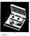
- Figure 9 shows a construction according to the invention, in which the amplifier component 8 is shown without a cover.
- the location of the loudspeaker element 7 can be in either the cover 2 or the base component 3.
- the handle component 10 can be attached to either component.
- the amplifier 8 be attached to either component.
- the reflex tube too can be moved to either part in the construction which can be opened.
- the location construction shown in Figures 1 - 9 offers some advantages. By means of the component location shown, the cover structure can be made simple while dividing the reflex tube between both parts achieves a large tube diameter.
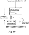
- the reflex enclosure of the loudspeaker element can be illustrated by a mass-spring system, which depicts qualitatively the operating principle of the loudspeaker.
- the reflect tube 5 built in the briefcase enclosure 1 consists of a Helmholtz resonator with the air volume of the loudspeaker chamber 30.
- the resonance arises from the effect of the acoustic air mass 21 of the tube and the series resonance circuit created by the acoustic compliance of the air volume of the loudspeaker chamber 30 of the enclosure. Close to the resonance frequency, the Helmholtz resonator amplifies the back radiation produced by the loudspeaker element.
- the enclosure-tube system 30, 21 is subject to resonance at a frequency, which, as is known, can be derived from the air volume of the enclosure's loudspeaker chamber 30, the diameter of the tube 5, and its length.
- f 0 c 2 ⁇ A LV in which f 0 is the resonance frequency, c is the speed of sound, A is the cross-sectional area of the tube, L is the length of the tube, and V is the volume of the enclosure.
- the internal volume of the briefcase sub-woofer 1 is determined on the basis of practice, as it is desired that the external dimensions of the loudspeaker will correspond to those of a conventional briefcase.
- the net volume of the loudspeaker chamber 30 thus remains 3.8 litres, when the volume of the amplifier and the resonance tube are deducted from the rest of the internal volume.
- the tube 5 can be described as an acoustic transfer line, which transports a plane wave. At the mouth 6 of the reflex tube 5, the discontinuity of the volume velocity causes resonance.
- the other detrimental resonances of the tube are harmonic multiples of the lowest resonance frequency.
- the satellite loudspeakers (auxiliary loudspeakers 4) to be connected to the briefcase sub-woofer set a requirement for the upper limit (about 250 Hz) of the reproduction band of the sub-woofer.
- the length of the reflex tube is selected to be as long as possible, but nevertheless such that the first detrimental resonance arises only above the reproduction band of the sub-woofer.
- the length of the tube is selected as 48 cm, in which case the first resonance arises at the frequency 357 Hz.
- a suitable compromise is sought between the surface area of the tube 5 and the tuning frequency of the enclosure.
- the cross-sectional surface area of the tube 5 must be sufficiently large for turbulence sounds not to arise.
- an increase in the surface area will mean increasing the length of the tube, if it is wished not to alter the tuning frequency.
- 14 cm 2 is selected as the cross-sectional surface area of the reflex tube.
- 48 Hz is obtained as the tuning frequency of the briefcase sub-woofer.
- the loudspeaker construction according to Figure 1 - 9 can be either an independent so-called sub-woofer intended only for bass reproduction, or alternatively part of a loudspeaker solution covering the entire audio frequency range.
- the loudspeaker solution according to the invention can also include an amplifier.
- the parts 2 and 3 of the loudspeaker construction can also be entirely detachable from each other, with the aid of two locking handles or similar.
- the term repeatedly detachable without dismantling the parts 2 and 3 of the loudspeaker construction refers, for example, to hinge or catch attachments.
- the main components of the loudspeaker construction 1 can preferably be manufactured, for example, from plastic using the injection-moulding technique.
- structures manufactured from aluminium are also advantageous, on account of their lightness and stiffness.
- the cover 2 and the base part 3 are referred in the aforementioned texts and Claims only to the co-ordinates of the figures. Naturally the solutions of the figures can, according to the invention, also be applied to other positions.
- auxiliary loudspeakers can be greater than 2, of course in that case the internal space of the system must be designed correspondingly.
- the system according to the invention can also contain an integrated sound source, such as an MP3 player, a CD player, or a mobile station equipped with music properties.
- an integrated sound source such as an MP3 player, a CD player, or a mobile station equipped with music properties.
- the data communications connections between the components of the device according to the invention can be either wired or wireless.
- the auxiliary loudspeakers 4 can communicate with the main apparatus wirelessly, for example, using Bluetooth or WLAN protocols.
- an infrared connection is also possible.
Landscapes
- Health & Medical Sciences (AREA)
- Otolaryngology (AREA)
- Physics & Mathematics (AREA)
- Engineering & Computer Science (AREA)
- Acoustics & Sound (AREA)
- Signal Processing (AREA)
- Details Of Audible-Bandwidth Transducers (AREA)
- Obtaining Desirable Characteristics In Audible-Bandwidth Transducers (AREA)
Description
- The present invention relates to a reflex loudspeaker construction according to the preamble of
Claim 1. - The invention is used particularly in connection with bass loudspeakers to create a so-called sub-woofer loudspeaker, in connection with a loudspeaker system.
- The most important demands set for a loudspeaker enclosure at low operating frequencies relate to an ability to withstand pressure differences with the least possible deformations (stiffness), and a freedom from structural resonance. Usually the enclosure is made from flat sheets, which if necessary are supported and stiffened inside the enclosure.
- One principle for an enclosure when reproducing low frequencies is a bass-reflex enclosure. In it, besides an opening for the loudspeaker element, there is also a second opening, to which a tube is often attached. The air in the tube creates an acoustic inductance (mass), while the air inside the enclosure for its part creates a capacitance (spring), the resonance frequency of this combination being dimensioned to operate with the loudspeaker enclosure. At low frequencies, the combination is resonant, so that the resonance circuit loads the loudspeaker element. The motion deviation of the element is then small and most of the radiation takes place through the reflex opening. When seeking to reproduce very low frequencies, the resonance frequency of the combination must be lowered, which takes place by increasing either the volume of the enclosure, or the acoustic mass of the quantity of air in the reflex channel. A large enclosure size is often a drawback, and is therefore avoided, thus unavoidably lengthening the reflex channel. Because at the resonance frequency radiation thus takes place through the reflex channel, the desired acoustic power will affect the flow velocity of the air in the tube. If the flow velocity in the tube becomes too great, the flow will become turbulent, causing extraneous sounds and compression. The minimum cross-sectional surface of the tube will therefore also depend on the desired acoustic power. When a greater acoustic power is desired, the cross-sectional surface is increased, but at the same time the tube becomes longer. A straight long tube will no longer fit inside the enclosure and is usually bent into various angles, but the sharp bends cause turbulence even at low flow velocities. Electro-technical solutions for the dimensioning of reflex loudspeakers and the related problems are described widely in the literature and disclosed in, among others, European patent
EP 0 322 686 . - A drawback of traditional reflex loudspeakers has been their large size and weight. This has become a problem, especially in portable operation.
-
GB patent application 2411539 US2002/085730 disclose a briefcase equipped with a loudspeaker, which briefcase when closed acts as a loudspeaker enclosure. Compared to reflex loudspeakers, closed enclosures are not as efficient as reflex loudspeakers. This leads to a large power consumption, or alternatively to a modest acoustic output power.US 6073770 discloses a briefcase having a shock absorbing function. - The present invention is intended to eliminate the defects of the state of the art disclosed above and for this purpose create an entirely new type of reflex loudspeaker construction.
- The invention is based on forming the reflex loudspeaker in a openable structure, for example, a briefcase. Locations for auxiliary loudspeakers, which are typically used to produce the uppermost frequencies of human hearing, are reserved in the acoustic space of the loudspeaker. The auxiliary loudspeakers are also used to create the desired properties in stereo or multi-channel operation.
- One application of the invention is thus a portable sound-reproduction apparatus.
- According to one preferred embodiment of the invention, the openable loudspeaker construction is a briefcase, the handle of which acts as a means for locking the loudspeaker enclosure and sealing it in the operating position.
- According to one preferred embodiment of the invention, the loudspeaker is equipped with an amplifier.
- More specifically, the reflex loudspeaker according to the invention is characterized by what is stated in the characterizing portion of
Claim 1. - Considerable advantages are gained with the aid of the invention.
- A sound-reproduction apparatus intended for portable use can be made very small, but nevertheless of high quality. Particularly the reproduction of low sounds can be implemented with high quality and with good efficiency. During transportation, the loudspeakers for the other ranges of audible sound can be conveniently placed inside the reflex loudspeaker.
- In a preferred embodiment of the invention, the sealing that is important to the operation of the loudspeaker can be ensured with the aid of a locking arrangement of the handle structure.
- The construction is further optimized by the fact that the reflex channel is part of the structure that stiffens the loudspeaker unit. Turbulence is minimized due to the spiral, gently shaped reflex channel while this in turn reduces extraneous sounds and compression. In addition, in several variations according to the invention it is possible to achieve solutions that are very economical in terms of manufacturing technique, because in the loudspeaker construction there are typically only 2 - 3 important structural components in addition to the loudspeaker element.
- In the following, the invention is examined with the aid of examples of applications according to the accompanying drawings.
-
Figure 1 shows a perspective view of one opened reflex loudspeaker according to the invention, seen from the front and at an angle. -
Figure 2 shows a side top view of the loudspeaker according toFigure 1 . -
Figure 3 shows a side view of the reflex loudspeaker according toFigure 1 , when it is closed. -
Figure 4a shows a front view of the loudspeaker according toFigure 1 . -
Figure 4b shows a top view of the loudspeaker according toFigure 1 . -
Figure 5 shows a schematic perspective view of a second loudspeaker according to the invention, in the opened position. -
Figure 6 shows a perspective view of the loudspeaker according toFigure 5 , in the closed position. -
Figure 7 shows a side perspective view of the loudspeaker according toFigure 5 , in the closed position. -
Figure 8 shows a side perspective view of the loudspeaker according toFigure 5 , closed and locked in its operating position with the aid of the handle. -
Figure 9 shows a perspective view of a third loudspeaker construction according to the invention, when opened. -
Figure 10 shows schematically the elements used for modelling a reflex loudspeaker. - In the application, the following terminology will be used, together with their reference numbers:
- 1
- reflex loudspeaker construction
- 2
- cover part
- 3
- base part
- 4
- auxiliary loudspeakers
- 5
- reflex channel
- 6
- reflex opening
- 7
- loudspeaker element
- 8
- amplifier
- 9
- securing slot
- 10
- handle
- 11
- handle attachment point
- 12
- cover locking pin
- 13
- connectors
- 14
- hinges
- 20
- moving mass of the loudspeaker element
- 21
- acoustic mass of the tube
- 22
- cubic capacity of the enclosure
- 23
- suspension of the cone
- 30
- loudspeaker chamber
- According to
Figure 1 , the bassreflex loudspeaker construction 1 is divided into acover component 2 and abase component 3. Theloudspeaker element 7 is attached to thebase component 3. The location of theloudspeaker element 7 means that, in the operating situation, it is mechanically protected under theloudspeaker construction 1. Thehandle 10 too is attached to thebase component 3. Thehandle 10 is hinged to the base component by means ofpins 11. A lockingslot 9, which in the closed position of theloudspeaker construction 1 tightens onto the cover's 2locking pin 12, is formed in thehandle component 10. Anamplifier 8, preferably enclosed in a sealed case, is also located in the base component. Also located in thebase component 3 is part of thereflex tube 5, which in the closed position of theloudspeaker construction 1, however, consists of a combination of the structures of thebase component 3 and the cover component, and terminates in thereflex opening 6. Spaces are also reserved in thebase component 3 forauxiliary loudspeakers 4. A light locking, which will hold theauxiliary loudspeakers 4 in place during transport, can also be combined with the spaces. When the auxiliary loudspeakers are removed from their places, aloudspeaker chamber 30, the volume of which is an important dimensioning parameter for a reflex loudspeaker, is formed inside the closed construction. - The following are a few example dimensions with the marking of
Figures 2 - 4b :dimension a of the reflex tube: 124 mm loudspeaker construction 1 width b: 339 mm auxiliary loudspeaker width c: 82 mm reflex tube width d: 21 mm auxiliary loudspeakers' n height e: 127 mm loudspeaker construction 1 thickness f: 80 mm loudspeaker construction depth g: 256 mm loudspeaker construction with handle h: 320.5 mm -
Figure 3 shows more details of the handle's 10 locking mechanism, which consists of aslot 9, onto which thelocking pin 12 of the cover locks. When the handle is rotated counterclockwise in the direction ofFigure 3 , the pin moves forwards in theslot 9. The right-hand edge of theslot 9 is arranged to be closer to theattachment pin 11 than the left-hand edge, so that when the handle is rotated counterclockwise, thecover component 2 tightens towards thebase component 3, thus sealing the loudspeaker construction. Theslot 9 is thus slightly spiral relative to theattachment pin 11.Figure 3 also shows theconnectors 13, which typically comprise connectors for theauxiliary loudspeakers 4 and also a connector for an external power supply. -
Figure 5 shows the position of thehandle 10, in which theslot 9 receives the lockingpin 12 of the cover.Figure 8 in turn shows the operating position of theloudspeaker construction 1, in which thehandle 10 has pressed thecover component 2 shut with theslot 9. Thehandle 10 also acts as a support and provides a free acoustic space for theloudspeaker element 7. - An alternative construction to the solution according to
Figure 5 is one in which when viewed from the handle component, there is a pin in thehandle 10, is a pin located on the end of an arm behind theattachment point 11, which acts with the corresponding slot structure of the second part, functionally in the same way as the construction ofFigure 5 . - It will be obvious to one versed in the art, that the locations of the said tightening mechanisms can vary from the cover component to the base component, as long as the operating principle of the tightening remains the same.
-
Figure 9 shows a construction according to the invention, in which theamplifier component 8 is shown without a cover. - Within the scope of the invention, the location of the
loudspeaker element 7 can be in either thecover 2 or thebase component 3. Similarly, thehandle component 10 can be attached to either component. Also theamplifier 8 be attached to either component. The reflex tube too can be moved to either part in the construction which can be opened. The location construction shown inFigures 1 - 9 offers some advantages. By means of the component location shown, the cover structure can be made simple while dividing the reflex tube between both parts achieves a large tube diameter. - In the following, the dimensioning of the reflect enclosure is described with reference to
Figure 10 . - The reflex enclosure of the loudspeaker element can be illustrated by a mass-spring system, which depicts qualitatively the operating principle of the loudspeaker.
- The
reflect tube 5 built in thebriefcase enclosure 1 consists of a Helmholtz resonator with the air volume of theloudspeaker chamber 30. The resonance arises from the effect of theacoustic air mass 21 of the tube and the series resonance circuit created by the acoustic compliance of the air volume of theloudspeaker chamber 30 of the enclosure. Close to the resonance frequency, the Helmholtz resonator amplifies the back radiation produced by the loudspeaker element. The enclosure-tube system loudspeaker chamber 30, the diameter of thetube 5, and its length.
- The internal volume of the
briefcase sub-woofer 1 is determined on the basis of practice, as it is desired that the external dimensions of the loudspeaker will correspond to those of a conventional briefcase. The net volume of theloudspeaker chamber 30 thus remains 3.8 litres, when the volume of the amplifier and the resonance tube are deducted from the rest of the internal volume. - When selecting the length of the
reflex tube 5, the functionally detrimental resonances have to be taken into consideration. Thetube 5 can be described as an acoustic transfer line, which transports a plane wave. At themouth 6 of thereflex tube 5, the discontinuity of the volume velocity causes resonance. - The lowest detrimental resonance of a tube equipped with an infinite flange arises at the frequency

reflex tube 5, and R is the radius of the reflex tube. The other detrimental resonances of the tube are harmonic multiples of the lowest resonance frequency. The satellite loudspeakers (auxiliary loudspeakers 4) to be connected to the briefcase sub-woofer set a requirement for the upper limit (about 250 Hz) of the reproduction band of the sub-woofer. The length of the reflex tube is selected to be as long as possible, but nevertheless such that the first detrimental resonance arises only above the reproduction band of the sub-woofer. The length of the tube is selected as 48 cm, in which case the first resonance arises at the frequency 357 Hz. - Finally, in dimensioning a suitable compromise is sought between the surface area of the
tube 5 and the tuning frequency of the enclosure. The cross-sectional surface area of thetube 5 must be sufficiently large for turbulence sounds not to arise. On the other hand, an increase in the surface area will mean increasing the length of the tube, if it is wished not to alter the tuning frequency. 14 cm2 is selected as the cross-sectional surface area of the reflex tube. Thus 48 Hz is obtained as the tuning frequency of the briefcase sub-woofer. - The loudspeaker construction according to
Figure 1 - 9 can be either an independent so-called sub-woofer intended only for bass reproduction, or alternatively part of a loudspeaker solution covering the entire audio frequency range. - Typically, the loudspeaker solution according to the invention can also include an amplifier.
- Even though the examples describe only one
loudspeaker element 7 attached to theloudspeaker construction 1, there can also be several, within the scope of the invention. - The
parts - In the present application, the term repeatedly detachable without dismantling the
parts - In terms of manufacturing technique, the main components of the
loudspeaker construction 1 can preferably be manufactured, for example, from plastic using the injection-moulding technique. - Within the scope of the invention, structures manufactured from aluminium are also advantageous, on account of their lightness and stiffness.
- The
cover 2 and thebase part 3 are referred in the aforementioned texts and Claims only to the co-ordinates of the figures. Naturally the solutions of the figures can, according to the invention, also be applied to other positions. - Naturally, the number of auxiliary loudspeakers can be greater than 2, of course in that case the internal space of the system must be designed correspondingly.
- The system according to the invention can also contain an integrated sound source, such as an MP3 player, a CD player, or a mobile station equipped with music properties.
- The data communications connections between the components of the device according to the invention can be either wired or wireless. Thus, for example the
auxiliary loudspeakers 4 can communicate with the main apparatus wirelessly, for example, using Bluetooth or WLAN protocols. According to the invention an infrared connection is also possible.
Claims (10)
- Portable reflex loudspeaker construction (1, 2, 3), which comprises- a loudspeaker chamber (30) forming a structure that is delimited by the reflex loudspeaker construction (1, 2, 3),- a reflex channel (5) connected to the loudspeaker chamber (30), which connects the loudspeaker chamber (30) to external space of the reflex loudspeaker construction (1, 2, 3), and- at least one loudspeaker element (7) connected to the reflex loudspeaker construction (1, 2, 3), which loudspeaker element (7) forms part of the structure delimiting the loudspeaker chamber (30),characterized in that- the reflex loudspeaker construction (1, 2, 3) is divided into a cover component (2) and a base component (3), which can be repeatedly detached at least partly from each other in order to use the loudspeaker chamber (30) as a transportation space, and- the reflex channel (5) is formed as two halves, one in each of said cover and base component of the reflex loudspeaker construction (1).
- Reflex loudspeaker construction (1, 2, 3) according to Claim 1, characterized in that the loudspeaker construction (1) forms a briefcase structure, in an operating state the inner part acts as a loudspeaker chamber (30) and in a transportation state as the storage and attachment space of auxiliary loudspeakers (4).
- Reflex loudspeaker construction (1, 2, 3) according to Claim 1 or 2, characterized in that its cover component (2) is hinged to its base component (3).
- Reflex loudspeaker construction (1, 2, 3) according to Claim 1 or 2, characterized in that the cover component (2) can be connected to its base component (3) by a catch attachment.
- Reflex loudspeaker construction (1, 2, 3) according to any of the above Claims, characterized in that the construction comprises means (10, 11, 9, 12) for sealing the loudspeaker construction in the operating situation.
- Reflex loudspeaker construction (1, 2, 3) according to Claim 5, characterized in that it comprises a construction (9) fitted to a handle (10), which when rotated tightens the loudspeaker construction (1, 2, 3) to seal it for the operating situation.
- Reflex loudspeaker construction (1, 2, 3) according to Claim 6, characterized in that locking apparatus comprises a spiral groove (9), in order to tighten a pin-like counter-piece (12).
- Reflex loudspeaker construction (1, 2, 3) according to any of the above Claims, characterized in that the amplifier (8), loudspeaker element (7), and handle (10) are located in the same component (3) in the reflex loudspeaker construction (1, 2, 3).
- Reflex loudspeaker construction (1, 2, 3) according to any of the above Claims, characterized in that in the operating situation the handle structure (10) detaches from the base of the base component (3), to create a free acoustic radiation space for the loudspeaker element (7).
- Reflex loudspeaker construction (1, 2, 3) according to any of the above Claims, characterized in that it forms a portable sound-reproduction apparatus.
Applications Claiming Priority (2)
| Application Number | Priority Date | Filing Date | Title |
|---|---|---|---|
| FI20051001A FI122126B (en) | 2005-10-05 | 2005-10-05 | Refleksikaiutinrakenne |
| PCT/FI2006/050426 WO2007039671A1 (en) | 2005-10-05 | 2006-10-04 | Reflex loudspeaker structure |
Publications (3)
| Publication Number | Publication Date |
|---|---|
| EP1949748A1 EP1949748A1 (en) | 2008-07-30 |
| EP1949748A4 EP1949748A4 (en) | 2010-02-24 |
| EP1949748B1 true EP1949748B1 (en) | 2017-06-21 |
Family
ID=35185144
Family Applications (1)
| Application Number | Title | Priority Date | Filing Date |
|---|---|---|---|
| EP06794143.5A Not-in-force EP1949748B1 (en) | 2005-10-05 | 2006-10-04 | Reflex loudspeaker structure |
Country Status (7)
| Country | Link |
|---|---|
| US (1) | US8150085B2 (en) |
| EP (1) | EP1949748B1 (en) |
| JP (1) | JP5254797B2 (en) |
| CN (2) | CN104967954A (en) |
| ES (1) | ES2634226T3 (en) |
| FI (1) | FI122126B (en) |
| WO (1) | WO2007039671A1 (en) |
Families Citing this family (8)
| Publication number | Priority date | Publication date | Assignee | Title |
|---|---|---|---|---|
| FI125235B (en) * | 2012-04-02 | 2015-07-31 | Genelec Oy | Loudspeakers and manufacturing process thereof |
| CN103051351B (en) * | 2012-11-01 | 2014-12-03 | 深圳市欧标实业发展有限公司 | Detachable and washable interphone for dustproof structure of loudspeaker |
| WO2015123658A1 (en) | 2014-02-14 | 2015-08-20 | Sonic Blocks, Inc. | Modular quick-connect a/v system and methods thereof |
| US20150326960A1 (en) * | 2014-02-18 | 2015-11-12 | Prescient Audio Mfg Llc | Miniature low profile speaker and case assembly |
| US9462361B2 (en) * | 2014-05-19 | 2016-10-04 | Logitech Europe S.A. | Sealed audio speaker design |
| FR3029727B1 (en) * | 2014-12-03 | 2018-01-26 | Sagemcom Broadband Sas | SUBWOOFER WITH STORAGE COMPARTMENT |
| CN107547992A (en) * | 2016-06-29 | 2018-01-05 | 宏碁股份有限公司 | Low-frequency extended loudspeaker and electronic device using same |
| CN111050255B (en) * | 2019-12-28 | 2021-10-12 | 陕西师范大学 | Receiving transducer with adjustable working frequency |
Family Cites Families (21)
| Publication number | Priority date | Publication date | Assignee | Title |
|---|---|---|---|---|
| US3687221A (en) * | 1971-03-08 | 1972-08-29 | Michel Paul Rene Bonnard | Sound reproduction acoustic enclosure |
| JPS5643984U (en) * | 1979-09-14 | 1981-04-21 | ||
| JP2605321B2 (en) | 1987-12-28 | 1997-04-30 | ヤマハ株式会社 | Sound equipment |
| US5046104A (en) * | 1989-11-30 | 1991-09-03 | Cambridge Soundworks, Inc. | Loudspeaker system |
| US5004105A (en) * | 1990-03-16 | 1991-04-02 | Tommyca Freadman | Packaging arrangement for transporting audio system components to and from an outdoor marine site |
| US5092424A (en) * | 1990-12-03 | 1992-03-03 | Bose Corporation | Electroacoustical transducing with at least three cascaded subchambers |
| US5176281A (en) * | 1991-09-20 | 1993-01-05 | Woodstream Corporation | Tackle box with lid-latching handle and removable carrying case |
| JPH05123213A (en) | 1991-10-11 | 1993-05-21 | Nifco Inc | Hand baggage case with reverse opening preventive mechanism |
| US5533097A (en) * | 1992-02-26 | 1996-07-02 | Motorola, Inc. | Portable communication system comprising a local and wide area communication units which can store a communication when the wide area communication system is not available |
| JPH0627956A (en) * | 1992-07-06 | 1994-02-04 | Casio Comput Co Ltd | Electronic musical instrument |
| FR2737074A1 (en) | 1995-07-21 | 1997-01-24 | Carlebach Yvan | Manufacturing process for portable acoustic container for loudspeaker - involves modifying standard liquid plastic container circular hole front and inserting loudspeaker |
| US6073770A (en) * | 1997-12-17 | 2000-06-13 | Park; Sang Jun | Briefcase having shock-absorbing function |
| JP3055558U (en) * | 1998-07-03 | 1999-01-22 | 義明 梁島 | Handbag with speaker |
| DE20019525U1 (en) * | 2000-11-17 | 2001-01-04 | Holland, Bert E., Ringwood | Briefcase or carrying case with integrated speaker system |
| FI112909B (en) * | 2001-02-19 | 2004-01-30 | Genelec Oy | Reflector speaker construction and method for providing the same |
| DE60335079D1 (en) * | 2003-04-22 | 2011-01-05 | Thomson Licensing | Electronic device with loudspeaker |
| JP2005033513A (en) * | 2003-07-14 | 2005-02-03 | Sharp Electronica Espana Sa | Speaker device and video display device |
| JP2005051605A (en) * | 2003-07-30 | 2005-02-24 | Sony Corp | Sound equipment |
| WO2005053355A2 (en) | 2003-10-30 | 2005-06-09 | New Transducers Limited | Carry case |
| GB2411539A (en) | 2004-02-27 | 2005-08-31 | Bevan Eric Lester | Travelling case with inbuilt speaker unit |
| JP4306627B2 (en) * | 2005-03-09 | 2009-08-05 | ソニー株式会社 | Bass reflex type speaker device, speaker box and image display device |
-
2005
- 2005-10-05 FI FI20051001A patent/FI122126B/en active IP Right Grant
-
2006
- 2006-10-04 US US12/083,077 patent/US8150085B2/en not_active Expired - Fee Related
- 2006-10-04 JP JP2008534036A patent/JP5254797B2/en not_active Expired - Fee Related
- 2006-10-04 CN CN201510103468.8A patent/CN104967954A/en active Pending
- 2006-10-04 ES ES06794143.5T patent/ES2634226T3/en active Active
- 2006-10-04 CN CNA2006800453880A patent/CN101322433A/en active Pending
- 2006-10-04 EP EP06794143.5A patent/EP1949748B1/en not_active Not-in-force
- 2006-10-04 WO PCT/FI2006/050426 patent/WO2007039671A1/en not_active Ceased
Non-Patent Citations (1)
| Title |
|---|
| None * |
Also Published As
| Publication number | Publication date |
|---|---|
| FI20051001A0 (en) | 2005-10-05 |
| FI122126B (en) | 2011-08-31 |
| US8150085B2 (en) | 2012-04-03 |
| FI20051001L (en) | 2007-04-06 |
| EP1949748A4 (en) | 2010-02-24 |
| WO2007039671A1 (en) | 2007-04-12 |
| JP2009512262A (en) | 2009-03-19 |
| US20090268934A1 (en) | 2009-10-29 |
| CN104967954A (en) | 2015-10-07 |
| ES2634226T3 (en) | 2017-09-27 |
| JP5254797B2 (en) | 2013-08-07 |
| EP1949748A1 (en) | 2008-07-30 |
| CN101322433A (en) | 2008-12-10 |
Similar Documents
| Publication | Publication Date | Title |
|---|---|---|
| US9232030B2 (en) | Amplifying cover for a portable audio device | |
| AU588168B2 (en) | Speaker adapted to corner-loaded installation | |
| US7778431B2 (en) | Sound enhancing stands for portable audio devices | |
| EP1577880A2 (en) | An audio system comprising a waveguide having an audio source at one end and an acoustic driver at another end | |
| CN202949552U (en) | Acoustic generator | |
| TWI500333B (en) | Speaker having a horizontal former | |
| CN210157378U (en) | Speaker housing and mobile device having the same | |
| JPH01254096A (en) | Acoustic equipment | |
| US8150085B2 (en) | Reflex loudspeaker structure | |
| GB2477020A (en) | Autoaugmented speaker bass reflex port is compliantly mounted to speaker baffle | |
| TW201136330A (en) | Speaker | |
| JPH05260579A (en) | Woofer device for television receiver | |
| US8489214B2 (en) | Dock without a power source for digital devices | |
| US7454030B2 (en) | Subwoofer with cascaded linear array of drivers | |
| JP3611854B2 (en) | Speaker system | |
| EP1452066B1 (en) | Bass-reflex loudspeaker system and method of manufacturing the same | |
| US4196790A (en) | Acoustic transducer having multiple frequency resonance | |
| CN101052237B (en) | Integrated built-in speaker with conduit | |
| US20050175206A1 (en) | Loudspeaker assembly having a folded bifurcated vent tube | |
| WO2008033579A2 (en) | Speaker system for portable multimedia player | |
| JP3086270B2 (en) | Speaker box | |
| JP2005260625A (en) | Speaker instrument | |
| JPH1066184A (en) | Speaker system | |
| CN1939088A (en) | Distributed acoustic cabinet | |
| JP3816016B2 (en) | Bass reflex type speaker device |
Legal Events
| Date | Code | Title | Description |
|---|---|---|---|
| PUAI | Public reference made under article 153(3) epc to a published international application that has entered the european phase |
Free format text: ORIGINAL CODE: 0009012 |
|
| 17P | Request for examination filed |
Effective date: 20080328 |
|
| AK | Designated contracting states |
Kind code of ref document: A1 Designated state(s): AT BE BG CH CY CZ DE DK EE ES FI FR GB GR HU IE IS IT LI LT LU LV MC NL PL PT RO SE SI SK TR |
|
| A4 | Supplementary search report drawn up and despatched |
Effective date: 20100125 |
|
| 17Q | First examination report despatched |
Effective date: 20100409 |
|
| DAX | Request for extension of the european patent (deleted) | ||
| GRAJ | Information related to disapproval of communication of intention to grant by the applicant or resumption of examination proceedings by the epo deleted |
Free format text: ORIGINAL CODE: EPIDOSDIGR1 |
|
| GRAP | Despatch of communication of intention to grant a patent |
Free format text: ORIGINAL CODE: EPIDOSNIGR1 |
|
| GRAP | Despatch of communication of intention to grant a patent |
Free format text: ORIGINAL CODE: EPIDOSNIGR1 |
|
| INTG | Intention to grant announced |
Effective date: 20170313 |
|
| RIN1 | Information on inventor provided before grant (corrected) |
Inventor name: MARTIKAINEN, ILPO |
|
| GRAS | Grant fee paid |
Free format text: ORIGINAL CODE: EPIDOSNIGR3 |
|
| GRAA | (expected) grant |
Free format text: ORIGINAL CODE: 0009210 |
|
| AK | Designated contracting states |
Kind code of ref document: B1 Designated state(s): AT BE BG CH CY CZ DE DK EE ES FI FR GB GR HU IE IS IT LI LT LU LV MC NL PL PT RO SE SI SK TR |
|
| REG | Reference to a national code |
Ref country code: GB Ref legal event code: FG4D |
|
| REG | Reference to a national code |
Ref country code: CH Ref legal event code: EP |
|
| REG | Reference to a national code |
Ref country code: IE Ref legal event code: FG4D |
|
| REG | Reference to a national code |
Ref country code: AT Ref legal event code: REF Ref document number: 903899 Country of ref document: AT Kind code of ref document: T Effective date: 20170715 |
|
| REG | Reference to a national code |
Ref country code: DE Ref legal event code: R096 Ref document number: 602006052853 Country of ref document: DE |
|
| REG | Reference to a national code |
Ref country code: ES Ref legal event code: FG2A Ref document number: 2634226 Country of ref document: ES Kind code of ref document: T3 Effective date: 20170927 |
|
| REG | Reference to a national code |
Ref country code: FR Ref legal event code: PLFP Year of fee payment: 12 |
|
| REG | Reference to a national code |
Ref country code: NL Ref legal event code: MP Effective date: 20170621 |
|
| PG25 | Lapsed in a contracting state [announced via postgrant information from national office to epo] |
Ref country code: LT Free format text: LAPSE BECAUSE OF FAILURE TO SUBMIT A TRANSLATION OF THE DESCRIPTION OR TO PAY THE FEE WITHIN THE PRESCRIBED TIME-LIMIT Effective date: 20170621 Ref country code: GR Free format text: LAPSE BECAUSE OF FAILURE TO SUBMIT A TRANSLATION OF THE DESCRIPTION OR TO PAY THE FEE WITHIN THE PRESCRIBED TIME-LIMIT Effective date: 20170922 |
|
| REG | Reference to a national code |
Ref country code: LT Ref legal event code: MG4D |
|
| REG | Reference to a national code |
Ref country code: AT Ref legal event code: MK05 Ref document number: 903899 Country of ref document: AT Kind code of ref document: T Effective date: 20170621 |
|
| PG25 | Lapsed in a contracting state [announced via postgrant information from national office to epo] |
Ref country code: BG Free format text: LAPSE BECAUSE OF FAILURE TO SUBMIT A TRANSLATION OF THE DESCRIPTION OR TO PAY THE FEE WITHIN THE PRESCRIBED TIME-LIMIT Effective date: 20170921 Ref country code: SE Free format text: LAPSE BECAUSE OF FAILURE TO SUBMIT A TRANSLATION OF THE DESCRIPTION OR TO PAY THE FEE WITHIN THE PRESCRIBED TIME-LIMIT Effective date: 20170621 Ref country code: LV Free format text: LAPSE BECAUSE OF FAILURE TO SUBMIT A TRANSLATION OF THE DESCRIPTION OR TO PAY THE FEE WITHIN THE PRESCRIBED TIME-LIMIT Effective date: 20170621 Ref country code: NL Free format text: LAPSE BECAUSE OF FAILURE TO SUBMIT A TRANSLATION OF THE DESCRIPTION OR TO PAY THE FEE WITHIN THE PRESCRIBED TIME-LIMIT Effective date: 20170621 |
|
| PG25 | Lapsed in a contracting state [announced via postgrant information from national office to epo] |
Ref country code: SK Free format text: LAPSE BECAUSE OF FAILURE TO SUBMIT A TRANSLATION OF THE DESCRIPTION OR TO PAY THE FEE WITHIN THE PRESCRIBED TIME-LIMIT Effective date: 20170621 Ref country code: CZ Free format text: LAPSE BECAUSE OF FAILURE TO SUBMIT A TRANSLATION OF THE DESCRIPTION OR TO PAY THE FEE WITHIN THE PRESCRIBED TIME-LIMIT Effective date: 20170621 Ref country code: EE Free format text: LAPSE BECAUSE OF FAILURE TO SUBMIT A TRANSLATION OF THE DESCRIPTION OR TO PAY THE FEE WITHIN THE PRESCRIBED TIME-LIMIT Effective date: 20170621 Ref country code: RO Free format text: LAPSE BECAUSE OF FAILURE TO SUBMIT A TRANSLATION OF THE DESCRIPTION OR TO PAY THE FEE WITHIN THE PRESCRIBED TIME-LIMIT Effective date: 20170621 Ref country code: AT Free format text: LAPSE BECAUSE OF FAILURE TO SUBMIT A TRANSLATION OF THE DESCRIPTION OR TO PAY THE FEE WITHIN THE PRESCRIBED TIME-LIMIT Effective date: 20170621 |
|
| PG25 | Lapsed in a contracting state [announced via postgrant information from national office to epo] |
Ref country code: PL Free format text: LAPSE BECAUSE OF FAILURE TO SUBMIT A TRANSLATION OF THE DESCRIPTION OR TO PAY THE FEE WITHIN THE PRESCRIBED TIME-LIMIT Effective date: 20170621 Ref country code: IS Free format text: LAPSE BECAUSE OF FAILURE TO SUBMIT A TRANSLATION OF THE DESCRIPTION OR TO PAY THE FEE WITHIN THE PRESCRIBED TIME-LIMIT Effective date: 20171021 |
|
| REG | Reference to a national code |
Ref country code: DE Ref legal event code: R097 Ref document number: 602006052853 Country of ref document: DE |
|
| PLBE | No opposition filed within time limit |
Free format text: ORIGINAL CODE: 0009261 |
|
| STAA | Information on the status of an ep patent application or granted ep patent |
Free format text: STATUS: NO OPPOSITION FILED WITHIN TIME LIMIT |
|
| PG25 | Lapsed in a contracting state [announced via postgrant information from national office to epo] |
Ref country code: DK Free format text: LAPSE BECAUSE OF FAILURE TO SUBMIT A TRANSLATION OF THE DESCRIPTION OR TO PAY THE FEE WITHIN THE PRESCRIBED TIME-LIMIT Effective date: 20170621 |
|
| 26N | No opposition filed |
Effective date: 20180322 |
|
| PG25 | Lapsed in a contracting state [announced via postgrant information from national office to epo] |
Ref country code: MC Free format text: LAPSE BECAUSE OF FAILURE TO SUBMIT A TRANSLATION OF THE DESCRIPTION OR TO PAY THE FEE WITHIN THE PRESCRIBED TIME-LIMIT Effective date: 20170621 |
|
| REG | Reference to a national code |
Ref country code: CH Ref legal event code: PL |
|
| REG | Reference to a national code |
Ref country code: IE Ref legal event code: MM4A |
|
| PG25 | Lapsed in a contracting state [announced via postgrant information from national office to epo] |
Ref country code: CH Free format text: LAPSE BECAUSE OF NON-PAYMENT OF DUE FEES Effective date: 20171031 Ref country code: LU Free format text: LAPSE BECAUSE OF NON-PAYMENT OF DUE FEES Effective date: 20171004 Ref country code: LI Free format text: LAPSE BECAUSE OF NON-PAYMENT OF DUE FEES Effective date: 20171031 |
|
| REG | Reference to a national code |
Ref country code: BE Ref legal event code: MM Effective date: 20171031 |
|
| PG25 | Lapsed in a contracting state [announced via postgrant information from national office to epo] |
Ref country code: SI Free format text: LAPSE BECAUSE OF FAILURE TO SUBMIT A TRANSLATION OF THE DESCRIPTION OR TO PAY THE FEE WITHIN THE PRESCRIBED TIME-LIMIT Effective date: 20170621 Ref country code: BE Free format text: LAPSE BECAUSE OF NON-PAYMENT OF DUE FEES Effective date: 20171031 |
|
| REG | Reference to a national code |
Ref country code: FR Ref legal event code: PLFP Year of fee payment: 13 |
|
| PG25 | Lapsed in a contracting state [announced via postgrant information from national office to epo] |
Ref country code: IE Free format text: LAPSE BECAUSE OF NON-PAYMENT OF DUE FEES Effective date: 20171004 |
|
| PG25 | Lapsed in a contracting state [announced via postgrant information from national office to epo] |
Ref country code: HU Free format text: LAPSE BECAUSE OF FAILURE TO SUBMIT A TRANSLATION OF THE DESCRIPTION OR TO PAY THE FEE WITHIN THE PRESCRIBED TIME-LIMIT; INVALID AB INITIO Effective date: 20061004 |
|
| PG25 | Lapsed in a contracting state [announced via postgrant information from national office to epo] |
Ref country code: CY Free format text: LAPSE BECAUSE OF NON-PAYMENT OF DUE FEES Effective date: 20170621 |
|
| PGFP | Annual fee paid to national office [announced via postgrant information from national office to epo] |
Ref country code: DE Payment date: 20191021 Year of fee payment: 14 Ref country code: FI Payment date: 20191011 Year of fee payment: 14 |
|
| PGFP | Annual fee paid to national office [announced via postgrant information from national office to epo] |
Ref country code: IT Payment date: 20191028 Year of fee payment: 14 Ref country code: ES Payment date: 20191122 Year of fee payment: 14 Ref country code: FR Payment date: 20191028 Year of fee payment: 14 |
|
| PG25 | Lapsed in a contracting state [announced via postgrant information from national office to epo] |
Ref country code: TR Free format text: LAPSE BECAUSE OF FAILURE TO SUBMIT A TRANSLATION OF THE DESCRIPTION OR TO PAY THE FEE WITHIN THE PRESCRIBED TIME-LIMIT Effective date: 20170621 |
|
| PGFP | Annual fee paid to national office [announced via postgrant information from national office to epo] |
Ref country code: GB Payment date: 20191021 Year of fee payment: 14 |
|
| PG25 | Lapsed in a contracting state [announced via postgrant information from national office to epo] |
Ref country code: PT Free format text: LAPSE BECAUSE OF FAILURE TO SUBMIT A TRANSLATION OF THE DESCRIPTION OR TO PAY THE FEE WITHIN THE PRESCRIBED TIME-LIMIT Effective date: 20170621 |
|
| REG | Reference to a national code |
Ref country code: DE Ref legal event code: R119 Ref document number: 602006052853 Country of ref document: DE |
|
| REG | Reference to a national code |
Ref country code: FI Ref legal event code: MAE |
|
| GBPC | Gb: european patent ceased through non-payment of renewal fee |
Effective date: 20201004 |
|
| PG25 | Lapsed in a contracting state [announced via postgrant information from national office to epo] |
Ref country code: DE Free format text: LAPSE BECAUSE OF NON-PAYMENT OF DUE FEES Effective date: 20210501 Ref country code: FR Free format text: LAPSE BECAUSE OF NON-PAYMENT OF DUE FEES Effective date: 20201031 Ref country code: FI Free format text: LAPSE BECAUSE OF NON-PAYMENT OF DUE FEES Effective date: 20201004 |
|
| PG25 | Lapsed in a contracting state [announced via postgrant information from national office to epo] |
Ref country code: GB Free format text: LAPSE BECAUSE OF NON-PAYMENT OF DUE FEES Effective date: 20201004 |
|
| PG25 | Lapsed in a contracting state [announced via postgrant information from national office to epo] |
Ref country code: IT Free format text: LAPSE BECAUSE OF NON-PAYMENT OF DUE FEES Effective date: 20201004 |
|
| REG | Reference to a national code |
Ref country code: ES Ref legal event code: FD2A Effective date: 20220120 |
|
| PG25 | Lapsed in a contracting state [announced via postgrant information from national office to epo] |
Ref country code: ES Free format text: LAPSE BECAUSE OF NON-PAYMENT OF DUE FEES Effective date: 20201005 |