EP1949402B1 - Lamp device and radiation source assembly as well as water disinfection system comprising such lamp device - Google Patents
Lamp device and radiation source assembly as well as water disinfection system comprising such lamp device Download PDFInfo
- Publication number
- EP1949402B1 EP1949402B1 EP06761095A EP06761095A EP1949402B1 EP 1949402 B1 EP1949402 B1 EP 1949402B1 EP 06761095 A EP06761095 A EP 06761095A EP 06761095 A EP06761095 A EP 06761095A EP 1949402 B1 EP1949402 B1 EP 1949402B1
- Authority
- EP
- European Patent Office
- Prior art keywords
- lamp device
- elongate electrical
- electrical connector
- device defined
- longitudinal axis
- Prior art date
- Legal status (The legal status is an assumption and is not a legal conclusion. Google has not performed a legal analysis and makes no representation as to the accuracy of the status listed.)
- Active
Links
Images



Classifications
-
- A—HUMAN NECESSITIES
- A61—MEDICAL OR VETERINARY SCIENCE; HYGIENE
- A61L—METHODS OR APPARATUS FOR STERILISING MATERIALS OR OBJECTS IN GENERAL; DISINFECTION, STERILISATION OR DEODORISATION OF AIR; CHEMICAL ASPECTS OF BANDAGES, DRESSINGS, ABSORBENT PADS OR SURGICAL ARTICLES; MATERIALS FOR BANDAGES, DRESSINGS, ABSORBENT PADS OR SURGICAL ARTICLES
- A61L2/00—Disinfection or sterilisation of materials or objects, in general; Accessories therefor
- A61L2/02—Disinfection or sterilisation of materials or objects, in general; Accessories therefor using physical processes
- A61L2/08—Radiation
- A61L2/10—Ultraviolet [UV] radiation
-
- C—CHEMISTRY; METALLURGY
- C02—TREATMENT OF WATER, WASTE WATER, SEWAGE, OR SLUDGE
- C02F—TREATMENT OF WATER, WASTE WATER, SEWAGE, OR SLUDGE
- C02F1/00—Treatment of water, waste water, or sewage
- C02F1/30—Treatment of water, waste water, or sewage by irradiation
- C02F1/32—Treatment of water, waste water, or sewage by irradiation with ultraviolet light
- C02F1/325—Irradiation devices or lamp constructions
-
- H—ELECTRICITY
- H01—ELECTRIC ELEMENTS
- H01J—ELECTRIC DISCHARGE TUBES OR DISCHARGE LAMPS
- H01J5/00—Details relating to vessels or to leading-in conductors common to two or more basic types of discharge tubes or lamps
- H01J5/50—Means forming part of the tube or lamps for the purpose of providing electrical connection to it
-
- H—ELECTRICITY
- H01—ELECTRIC ELEMENTS
- H01J—ELECTRIC DISCHARGE TUBES OR DISCHARGE LAMPS
- H01J5/00—Details relating to vessels or to leading-in conductors common to two or more basic types of discharge tubes or lamps
- H01J5/50—Means forming part of the tube or lamps for the purpose of providing electrical connection to it
- H01J5/54—Means forming part of the tube or lamps for the purpose of providing electrical connection to it supported by a separate part, e.g. base
- H01J5/56—Shape of the separate part
-
- H—ELECTRICITY
- H01—ELECTRIC ELEMENTS
- H01R—ELECTRICALLY-CONDUCTIVE CONNECTIONS; STRUCTURAL ASSOCIATIONS OF A PLURALITY OF MUTUALLY-INSULATED ELECTRICAL CONNECTING ELEMENTS; COUPLING DEVICES; CURRENT COLLECTORS
- H01R33/00—Coupling devices specially adapted for supporting apparatus and having one part acting as a holder providing support and electrical connection via a counterpart which is structurally associated with the apparatus, e.g. lamp holders; Separate parts thereof
- H01R33/05—Two-pole devices
- H01R33/06—Two-pole devices with two current-carrying pins, blades or analogous contacts, having their axes parallel to each other
- H01R33/08—Two-pole devices with two current-carrying pins, blades or analogous contacts, having their axes parallel to each other for supporting tubular fluorescent lamp
- H01R33/0809—Two-pole devices with two current-carrying pins, blades or analogous contacts, having their axes parallel to each other for supporting tubular fluorescent lamp having contacts on one side only
-
- H—ELECTRICITY
- H01—ELECTRIC ELEMENTS
- H01R—ELECTRICALLY-CONDUCTIVE CONNECTIONS; STRUCTURAL ASSOCIATIONS OF A PLURALITY OF MUTUALLY-INSULATED ELECTRICAL CONNECTING ELEMENTS; COUPLING DEVICES; CURRENT COLLECTORS
- H01R33/00—Coupling devices specially adapted for supporting apparatus and having one part acting as a holder providing support and electrical connection via a counterpart which is structurally associated with the apparatus, e.g. lamp holders; Separate parts thereof
- H01R33/965—Dustproof, splashproof, drip-proof, waterproof, or flameproof holders
-
- H—ELECTRICITY
- H01—ELECTRIC ELEMENTS
- H01R—ELECTRICALLY-CONDUCTIVE CONNECTIONS; STRUCTURAL ASSOCIATIONS OF A PLURALITY OF MUTUALLY-INSULATED ELECTRICAL CONNECTING ELEMENTS; COUPLING DEVICES; CURRENT COLLECTORS
- H01R33/00—Coupling devices specially adapted for supporting apparatus and having one part acting as a holder providing support and electrical connection via a counterpart which is structurally associated with the apparatus, e.g. lamp holders; Separate parts thereof
- H01R33/97—Holders with separate means to prevent loosening of the coupling or unauthorised removal of apparatus held
-
- C—CHEMISTRY; METALLURGY
- C02—TREATMENT OF WATER, WASTE WATER, SEWAGE, OR SLUDGE
- C02F—TREATMENT OF WATER, WASTE WATER, SEWAGE, OR SLUDGE
- C02F2201/00—Apparatus for treatment of water, waste water or sewage
- C02F2201/002—Construction details of the apparatus
- C02F2201/004—Seals, connections
Definitions
- the present invention relates to a lamp device. In another of its aspects, the present invention relates to a radiation source assembly. In yet another of its aspects, the present invention relates to a water disinfection system.
- Fluid treatment systems such as water disinfection systems are generally known in the art.
- a low pressure discharge lamp includes a bulb with a pair of closed ends, and a pair of bases attached to the ends of the bulb, respectively.
- Each base has a cylindrical base body into which the end of bulb is inserted, and a pair of receiving terminals electrically connected to an electrode in the bulb and protruding from the base body in a direction perpendicular to the axis of the bulb.
- Document JP-A-62 115 625 discloses a base for tubular bulb.
- a first member is formed through integral molding of the bottom of the bulb base, namely a bottom face and a terminal face upstanding from said bottom face.
- the terminal face is provided with four contact terminal pins projecting so that they may pierce the terminal face, while said pins being electrically connected to an external socket.
- UV radiation ultraviolet radiation
- Such prior art fluid treatment systems employ an ultraviolet radiation lamp to emit radiation of a particular wavelength or range of wavelengths (usually between 185 and 400 nm) to kill, sterilize and/or prevent replication of microorganisms (bacteria, viruses, pathogens and the like) that may be present in the fluid.
- a particular wavelength or range of wavelengths usually between 185 and 400 nm
- Conventional ultraviolet radiation lamps include low pressure lamps, medium pressure lamps, low pressure high output lamps and the like.
- the electrical connection pins are elongate and are disposed such that the axes of the pins are parallel with the longitudinal axes of radiation lamp.
- the electrical connection is made by pushing an end cap or other connection base on to the pins in a direction parallel to the longitudinal axis of the radiation lamp.
- the radiation lamp is immersed in a flow of water and turbulence created within that water treatment system invariably imparts a vibratory motion to the lamps which frequently results in lamps being vibrated or shaken loose of its electrical connection base or socket thereby causing the lamps to be rendered completely or intermittently inoperative.
- the water being treated may not be fully disinfected.
- the present invention provides a lamp device according to claim 1.
- the present invention relates to a radiation source assembly comprising such a lamp device, together with a radiation transparent protective sleeve.
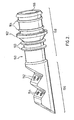
- FIG. 1-8 there is shown in detail the electrical connection portion of a radiation lamp and/or the connection thereof to a complementary base unit. The remaining detail of the lamp is not shown for easier understanding. However, those of skill in the art will readily recognize how the specific connection shown in the Figures can be implemented in a lamp design by reference to the various prior art patents referred to above.
- first electrical base unit 100 and a second electrical base unit 150.
- First electrical connection base unit 100 comprises a housing 102.
- An end portion 104 of unit 100 comprises a first pair of electrical connectors 106 and a second pair of electrical connectors 108.
- In portion 104 comprises an undulating shape having a series of peaks 110 and valleys 112. Electrical connectors 106,108 are connected to wire or other suitable electrical conveyance (not shown) disposed within housing 102 which is than connected to the radiation-emitting cavity of a lamp in a conventional manner.
- base unit 150 comprises a first pair of electrical receptacles 152 and a second pair of electrical receptacles 154. These receptacles are disposed at a first end portion 156 of base unit 150. Disposed at another end portion 158 of base unit 150 is a sealing system which functions in a manner similar to that described in United States patents 4,872,980 and 5,006,244 referred to above. Specifically, end portion 158 comprises a pair of annular seals 160 that serve to seal the interior of a radiation transparent protective sleeve ( Figure 4 ) placed over the radiation lamp.
- stop portion 162 that serves as stop for the open end of protective sleeves surrounding the lamp.
- Portion 158 further comprises a pair of annular seals 164 that serve to seal against water ingress into the frame of a module in which the lamp is placed (again, reference can be made to United States patent 4,872,980 and 5,006,244 for further details on the function of the seals).
- Electrical receptacles 152,154 are wired in a conventional manner with the electrical wires or other electrical conveyance emerging from an aperture 166 in end portion 158 connection unit 150.
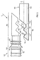
- base units 100 and 150 When it is desired to engage base unit 100 with base unit 150, the base units are aligned as shown in Figure 3 and moved with respect to one another in the direction of arrow C.
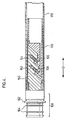
- the engaged components are shown in Figure 4 and a radiation transparent protective sleeve 170 encases the connected units 100 and 150.
- a radiation transparent protective sleeve 170 encases the connected units 100 and 150.
- the connection will withstand vibration forces conveyed to the radiation lamp.
- base unit 100 will not separate from base unit 150 in a direction of arrow D, particularly when radiation transparent protective sleeve 170 is disposed over the connection.
- Figures 5-8 there is illustrated a second embodiment of the preferred invention.
- reference numerals will be used wherein the last two digits correspond to the same relevance appearing in Figures 1-4 and the first numeral will be "2" in Figures 5-8 instead of "1" in Figures 1-4 .
- the embodiment illustrated in Figures 5-8 comprises electrical connectors 206,208 that are angled away ( ⁇ ) from the radiation-emitting cavity.
- the cross-sectional shape base unit 200 in Figures 5-8 comprises a single valley 212 instead of the pair of valleys 112 in the embodiment illustrated in Figures 1-4 .
- cross-sectional shape base unit 200 in Figures 5-8 comprises a single peak 210 instead of the pair of valleys 110 in the embodiment illustrated in Figures 1-4 .
- the embodiment shown in Figures 5-8 may be used in a manner similar to that described above with respect to Figures 1-4 .
Landscapes
- Health & Medical Sciences (AREA)
- Life Sciences & Earth Sciences (AREA)
- Environmental & Geological Engineering (AREA)
- Water Supply & Treatment (AREA)
- General Health & Medical Sciences (AREA)
- Public Health (AREA)
- Veterinary Medicine (AREA)
- Toxicology (AREA)
- Hydrology & Water Resources (AREA)
- Engineering & Computer Science (AREA)
- Epidemiology (AREA)
- Animal Behavior & Ethology (AREA)
- Chemical & Material Sciences (AREA)
- Organic Chemistry (AREA)
- Physical Water Treatments (AREA)
- Apparatus For Disinfection Or Sterilisation (AREA)
- Arrangement Of Elements, Cooling, Sealing, Or The Like Of Lighting Devices (AREA)
- Led Device Packages (AREA)
- Resistance Heating (AREA)
- Non-Portable Lighting Devices Or Systems Thereof (AREA)
Abstract
Description
- In one of its aspects, the present invention relates to a lamp device. In another of its aspects, the present invention relates to a radiation source assembly. In yet another of its aspects, the present invention relates to a water disinfection system.
- Fluid treatment systems such as water disinfection systems are generally known in the art.
- See, for example, one or more of the following United States patents:
-
Re36,896 , -
3,418,370 , -
4,482,809 , -
4,872,980 , -
5,006,244 , -
5,471,063 , -
5,504,355 , -
5,538,210 , -
6,342,188 , -
6,500,346 , -
6,507,028 , -
6,646,269 , -
6,674,084 , -
6,803,586 , and 6,863,078. - Document
EP-A-0 281 079 discloses a low pressure discharge lamp includes a bulb with a pair of closed ends, and a pair of bases attached to the ends of the bulb, respectively. Each base has a cylindrical base body into which the end of bulb is inserted, and a pair of receiving terminals electrically connected to an electrode in the bulb and protruding from the base body in a direction perpendicular to the axis of the bulb. - Document
JP-A-62 115 625 - Many of the above-identified United States patents teach fluid treatment systems that employ ultraviolet (UV) radiation to kill, sterilize and/or prevent replication of microorganisms (bacteria, viruses, pathogens and the like) that may be present in the fluid.
- Generally, such prior art fluid treatment systems employ an ultraviolet radiation lamp to emit radiation of a particular wavelength or range of wavelengths (usually between 185 and 400 nm) to kill, sterilize and/or prevent replication of microorganisms (bacteria, viruses, pathogens and the like) that may be present in the fluid.
- Conventional ultraviolet radiation lamps include low pressure lamps, medium pressure lamps, low pressure high output lamps and the like.
- In more recent years, it has become conventional to use such ultraviolet lamps configured to have all of the electrical connections disposed at one end of the lamp. See, for example,
Figures 2-8 of United States patent4,700,101 [Ellner et al. (Ellner)] andFigures 1 ,2 and4 of United States patent5,166,527 [Solymar]. - As can be seen from the prior art radiation lamps taught by Ellner and Solymar, the electrical connection pins are elongate and are disposed such that the axes of the pins are parallel with the longitudinal axes of radiation lamp. In other words, the electrical connection is made by pushing an end cap or other connection base on to the pins in a direction parallel to the longitudinal axis of the radiation lamp.
- The problem with this approach is that in many applications, the radiation lamp is immersed in a flow of water and turbulence created within that water treatment system invariably imparts a vibratory motion to the lamps which frequently results in lamps being vibrated or shaken loose of its electrical connection base or socket thereby causing the lamps to be rendered completely or intermittently inoperative. When such an event occurs, the water being treated may not be fully disinfected.
- More recently, the prior art has attempted to address this problem by using a relatively complicated mechanical connection (e.g., a so-called "push-and-twist" connection) to secure the lamp to the connection base. See, for example, United States patent
5,422,487 [Sauska et al (Sauska)] and United States patent6,884,103 [Kovacs ]. The problem with these approaches is the complexity of the mechanical connection between the lamp and the base unit requiring the use of springs, specialized connection lugs and the like. Further, a connection system which is predicated on a dual motion system such that pushing and twisting gives rise to a higher incidents of lamp breakage and other damage to the module by field personal. - Accordingly, there remains the need in the art for a lamp device, particularly a radiation lamp, which will provide a reliable electric connection on the one hand, yet be relatively inexpensive, uncomplicated and simple to implement on the other hand.
- It is an object of the present invention to obviate or mitigate at least one of the above-mentioned disadvantages of the prior art.
- Accordingly, in one of its aspects, the present invention provides a lamp device according to claim 1.
- In another of its aspects, the present invention relates to a radiation source assembly comprising such a lamp device, together with a radiation transparent protective sleeve.
- Other aspects of the present invention relate to water disinfection systems incorporating the above lamp device, and radiation source assembly, respectively.
- Embodiments of the present invention will be described with reference to the accompanying drawings, wherein like reference numerals denote like parts, and in which:
-
Figures 1-4 illustrate components of a first preferred embodiment of the present lamp device; and -
Figures 5-8 illustrate portions of a second preferred embodiment of the present lamp device. - Preferred embodiments of the present invention will be described below with reference to
Figures 1-8 . InFigures 1-8 , there is shown in detail the electrical connection portion of a radiation lamp and/or the connection thereof to a complementary base unit. The remaining detail of the lamp is not shown for easier understanding. However, those of skill in the art will readily recognize how the specific connection shown in the Figures can be implemented in a lamp design by reference to the various prior art patents referred to above. - With reference to
Figures 1-4 , there is illustrated a firstelectrical base unit 100 and a secondelectrical base unit 150. - First electrical
connection base unit 100 comprises ahousing 102. Anend portion 104 ofunit 100 comprises a first pair ofelectrical connectors 106 and a second pair ofelectrical connectors 108. - In
portion 104 comprises an undulating shape having a series ofpeaks 110 andvalleys 112. Electrical connectors 106,108 are connected to wire or other suitable electrical conveyance (not shown) disposed withinhousing 102 which is than connected to the radiation-emitting cavity of a lamp in a conventional manner. - With particular reference to
Figure 2 , there is illustrated an enlarged view ofbase unit 150. As shown,base unit 150 comprises a first pair ofelectrical receptacles 152 and a second pair ofelectrical receptacles 154. These receptacles are disposed at afirst end portion 156 ofbase unit 150. Disposed at anotherend portion 158 ofbase unit 150 is a sealing system which functions in a manner similar to that described in United States patents4,872,980 and5,006,244 referred to above. Specifically,end portion 158 comprises a pair ofannular seals 160 that serve to seal the interior of a radiation transparent protective sleeve (Figure 4 ) placed over the radiation lamp. - Also disposed on
end portion 158 is astop portion 162 that serves as stop for the open end of protective sleeves surrounding the lamp. -
- Electrical receptacles 152,154 are wired in a conventional manner with the electrical wires or other electrical conveyance emerging from an
aperture 166 inend portion 158connection unit 150. - With particular reference to
Figure 3 , it will be seen that whenbase unit 100 is connected to the remaining components of the radiation lamp, there will be a longitudinal axes shown at line A throughbase unit 100 and the remainder of the lamp. Further, it will be seen that electrical connector 106,108 are elongate and have a longitudinal axis through line B. An important feature of this preferred embodiment is that line B is non-parallel with respect to line A. In other words, the longitudinal axes through electrical connectors 106,108 is in a non-parallel relationship with the longitudinal axes throughbase unit 100 and the remainder of the radiation lamp. In the specific embodiment shown, electrical connectors 106,108 are disposed at an acute angle α toward the radiation-emitting cavity (not shown) of the lamp. - When it is desired to engage
base unit 100 withbase unit 150, the base units are aligned as shown inFigure 3 and moved with respect to one another in the direction of arrow C. The engaged components are shown inFigure 4 and a radiation transparentprotective sleeve 170 encases theconnected units Figure 4 , the connection will withstand vibration forces conveyed to the radiation lamp. Specifically,base unit 100 will not separate frombase unit 150 in a direction of arrow D, particularly when radiation transparentprotective sleeve 170 is disposed over the connection. - With reference to
Figures 5-8 , there is illustrated a second embodiment of the preferred invention. In the description ofFigures 5-8 , reference numerals will be used wherein the last two digits correspond to the same relevance appearing inFigures 1-4 and the first numeral will be "2" inFigures 5-8 instead of "1" inFigures 1-4 . Thus, it will be seen that a first major difference between the two embodiments is that the embodiment illustrated inFigures 5-8 comprises electrical connectors 206,208 that are angled away (β) from the radiation-emitting cavity. Another difference is that the cross-sectionalshape base unit 200 inFigures 5-8 comprises asingle valley 212 instead of the pair ofvalleys 112 in the embodiment illustrated inFigures 1-4 . Yet another difference is that the cross-sectionalshape base unit 200 inFigures 5-8 comprises asingle peak 210 instead of the pair ofvalleys 110 in the embodiment illustrated inFigures 1-4 . Otherwise, the embodiment shown inFigures 5-8 may be used in a manner similar to that described above with respect toFigures 1-4 . - While this invention has been described with reference to illustrative embodiments and examples, the description is not intended to be construed in a limiting sense. Thus, various modifications of the illustrative embodiments, as well as other embodiments of the invention, will be apparent to persons skilled in the art upon reference to this description. For example, it is possible to reverse the arrangement of electrical connectors and electrical receptacles in the illustrated embodiments - i.e., the electrical connectors would be disposed in electrical connection base unit 150,250 and the electrical receptacles would be disposed in electrical connection base unit 100,200. Also, it is possible to have a mixture of electrical connectors and electrical receptacles on electrical connection base unit 100,200 and a complementary mixture of electrical connectors and electrical receptacles on electrical connection base unit 150,250. Yet another modification of the illustrated embodiments relates to the use of electrical connection bases that, in cross-section contain no peaks or valleys. It is therefore contemplated that the appended claims will cover any such modifications or embodiments.
Claims (16)
- A lamp device comprising an elongated radiation emitting cavity having a longitudinal axis (A), a first elongate electrical connector (106) and a second elongate electrical connector (108), each of the first elongate electrical connector and the second elongate connector being:(i) non-parallel with respect to the longitudinal axis, and(ii) disposed in a base portion (104) at one end of the lamp device,characterized in that the first elongate electrical connector and the second elongate connector are disposed at an acute angle (α, β) with respect to the longitudinal axis (A).
- The lamp device defined in Claim 2, wherein the first elongate electrical connector and the second elongate electrical connector are substantially parallel with respect to one another.
- The lamp device defined in any one of Claims 1-2, wherein the first elongate electrical connector and the second elongate connector are in a spaced relationship along the longitudinal axis.
- The lamp device defined in any one of Claims 1-2, wherein the first elongate electrical connector and the second elongate electrical connector are aligned in a spaced relationship along the longitudinal axis.
- The lamp device defined in Claim 4, wherein a cross-section of the base portion containing the longitudinal axis comprises an undulating shape.
- The lamp device defined in Claim 4, wherein a cross-section of the base portion containing the longitudinal axis comprises at least one peak and at least one valley.
- The lamp device defined in Claim 6, wherein the first elongate electrical connector and the second elongate electrical connector are offset with regard to the at least one peak or the at least one valley.
- The lamp device defined in Claim 6, wherein the first elongate electrical connector and the second elongate electrical connector are offset with regard to both of the at least one peak and the at least one valley.
- The lamp device defined in Claim 4, wherein a cross-section of the base portion containing the longitudinal axis comprises a single peak and a single valley.
- The lamp device defined in any one of Claims 1-9, wherein both of the first elongate electrical connector and the second elongate electrical connector comprises a male portion of a male-female connection system.
- The lamp device defined in any one of Claims 1-10, comprising a pair of first elongate electrical connectors and a pair of second elongate electrical connectors.
- The lamp device defined in Claim 11, wherein the pair of first elongate electrical connectors are in substantial alignment along a line orthogonal to the longitudinal axis.
- The lamp device defined in Claim 11, wherein the pair of second elongate electrical connectors are in substantial alignment along a line orthogonal to the longitudinal axis.
- The lamp device defined in Claim 11, wherein the pair of first elongate electrical connectors and the pair of second elongate electrical connectors are in substantial alignment along a line orthogonal to the longitudinal axis.
- A radiation source assembly comprising the lamp device defined in any one of Claims 1-14, together with a radiation transparent protective sleeve.
- A water disinfection system comprising the lamp device defined in any one of Claims 1-14.
Applications Claiming Priority (2)
| Application Number | Priority Date | Filing Date | Title |
|---|---|---|---|
| US69350205P | 2005-06-24 | 2005-06-24 | |
| PCT/CA2006/001040 WO2006136026A1 (en) | 2005-06-24 | 2006-06-27 | Radiation lamp and radiation source module incorporating same |
Publications (3)
| Publication Number | Publication Date |
|---|---|
| EP1949402A1 EP1949402A1 (en) | 2008-07-30 |
| EP1949402A4 EP1949402A4 (en) | 2010-03-17 |
| EP1949402B1 true EP1949402B1 (en) | 2011-04-13 |
Family
ID=37570070
Family Applications (1)
| Application Number | Title | Priority Date | Filing Date |
|---|---|---|---|
| EP06761095A Active EP1949402B1 (en) | 2005-06-24 | 2006-06-27 | Lamp device and radiation source assembly as well as water disinfection system comprising such lamp device |
Country Status (10)
| Country | Link |
|---|---|
| EP (1) | EP1949402B1 (en) |
| CN (1) | CN101228606B (en) |
| AT (1) | ATE505805T1 (en) |
| AU (1) | AU2006261548B2 (en) |
| CA (1) | CA2613147C (en) |
| DE (1) | DE602006021339D1 (en) |
| ES (1) | ES2364965T3 (en) |
| PT (1) | PT1949402E (en) |
| RU (1) | RU2430445C2 (en) |
| WO (1) | WO2006136026A1 (en) |
Families Citing this family (10)
| Publication number | Priority date | Publication date | Assignee | Title |
|---|---|---|---|---|
| US7569981B1 (en) | 2005-02-22 | 2009-08-04 | Light Sources, Inc. | Ultraviolet germicidal lamp base and socket |
| CA2630609C (en) * | 2005-11-22 | 2020-04-07 | Trojan Technologies Inc. | Radiation lamp and radiation source module incorporating same |
| US8021189B2 (en) | 2006-02-27 | 2011-09-20 | Light Sources Inc. | Ultraviolet lamp for use in water purifiers |
| US7795813B2 (en) * | 2006-02-27 | 2010-09-14 | Light Sources, Inc. | Ultraviolet lamp for use in water purifiers |
| US7604505B2 (en) | 2006-02-27 | 2009-10-20 | Light Sources, Inc. | Ultraviolet lamp for use in water purifiers |
| US8040032B2 (en) | 2006-09-25 | 2011-10-18 | Lightsources Inc. | Smooth action, spring loaded, twist locking, radial lugged safety connector for lamp |
| US7661977B2 (en) | 2006-09-25 | 2010-02-16 | Light Sources, Inc. | Snap-lock connector |
| WO2008039448A2 (en) | 2006-09-25 | 2008-04-03 | Lightsources Inc. | Snap-lock connector |
| US9062870B2 (en) | 2013-05-10 | 2015-06-23 | Caldesso, Llc | UV bulb configuration |
| CN104092178B (en) * | 2014-06-27 | 2016-08-24 | 国家电网公司 | A kind of cable connector attachment structure |
Family Cites Families (10)
| Publication number | Priority date | Publication date | Assignee | Title |
|---|---|---|---|---|
| US4700101A (en) | 1985-02-07 | 1987-10-13 | Sidney Ellner | Elongated tubular lamp construction |
| JPS62115625A (en) * | 1985-11-15 | 1987-05-27 | Toshiba Corp | Base for tubular bulb |
| EP0281079A3 (en) * | 1987-03-05 | 1990-06-27 | Kabushiki Kaisha Toshiba | Low pressure discharge lamp |
| US5166527A (en) | 1991-12-09 | 1992-11-24 | Puroflow Incorporated | Ultraviolet lamp for use in water purifiers |
| US5422487A (en) * | 1994-07-27 | 1995-06-06 | Light Sources, Inc. | Waste water purification system with complementary interlocking germicidal lamp and socket construction |
| US6254252B1 (en) * | 1999-05-14 | 2001-07-03 | Osram Sylvania Inc. | Lamp and lamp base assembly |
| US6488510B2 (en) * | 2001-03-21 | 2002-12-03 | Long-Beam Enterprise Co., Ltd. | Rotary-plug wall lamp |
| US20020168881A1 (en) * | 2001-05-11 | 2002-11-14 | Cun-Yu Hwang | Omnidirectionally adjustable wall lamp plug |
| RU2236060C1 (en) * | 2002-12-25 | 2004-09-10 | Закрытое акционерное общество Научно-производственный центр "СОЛИТОН-НТТ" | Gas-discharge ultraviolet radiation source |
| FR2855511B1 (en) * | 2003-06-02 | 2006-06-16 | Otv Sa | DEVICE FOR DISINFECTING WATER BY ULTRAVIOLET RADIATION |
-
2006
- 2006-06-27 DE DE602006021339T patent/DE602006021339D1/en active Active
- 2006-06-27 AT AT06761095T patent/ATE505805T1/en not_active IP Right Cessation
- 2006-06-27 CN CN2006800226158A patent/CN101228606B/en active Active
- 2006-06-27 WO PCT/CA2006/001040 patent/WO2006136026A1/en not_active Ceased
- 2006-06-27 PT PT06761095T patent/PT1949402E/en unknown
- 2006-06-27 RU RU2008102161/07A patent/RU2430445C2/en not_active IP Right Cessation
- 2006-06-27 ES ES06761095T patent/ES2364965T3/en active Active
- 2006-06-27 CA CA2613147A patent/CA2613147C/en active Active
- 2006-06-27 AU AU2006261548A patent/AU2006261548B2/en not_active Ceased
- 2006-06-27 EP EP06761095A patent/EP1949402B1/en active Active
Also Published As
| Publication number | Publication date |
|---|---|
| CN101228606B (en) | 2012-03-21 |
| ATE505805T1 (en) | 2011-04-15 |
| CA2613147A1 (en) | 2006-12-28 |
| PT1949402E (en) | 2011-07-08 |
| AU2006261548A1 (en) | 2006-12-28 |
| CA2613147C (en) | 2013-11-26 |
| RU2008102161A (en) | 2009-07-27 |
| DE602006021339D1 (en) | 2011-05-26 |
| CN101228606A (en) | 2008-07-23 |
| EP1949402A1 (en) | 2008-07-30 |
| ES2364965T3 (en) | 2011-09-19 |
| EP1949402A4 (en) | 2010-03-17 |
| AU2006261548B2 (en) | 2012-08-09 |
| RU2430445C2 (en) | 2011-09-27 |
| WO2006136026A1 (en) | 2006-12-28 |
Similar Documents
| Publication | Publication Date | Title |
|---|---|---|
| US8167654B2 (en) | Radiation lamp and radiation source module incorporating same | |
| EP2070164B9 (en) | Snap-lock connector | |
| US7604505B2 (en) | Ultraviolet lamp for use in water purifiers | |
| US8021189B2 (en) | Ultraviolet lamp for use in water purifiers | |
| US8040032B2 (en) | Smooth action, spring loaded, twist locking, radial lugged safety connector for lamp | |
| US12183569B2 (en) | UV radiation source assembly | |
| CA2613147C (en) | Radiation lamp and radiation source module incorporating same | |
| US7795813B2 (en) | Ultraviolet lamp for use in water purifiers | |
| US9895457B2 (en) | Radiation lamp and radiation source module incorporating same |
Legal Events
| Date | Code | Title | Description |
|---|---|---|---|
| PUAI | Public reference made under article 153(3) epc to a published international application that has entered the european phase |
Free format text: ORIGINAL CODE: 0009012 |
|
| 17P | Request for examination filed |
Effective date: 20080130 |
|
| AK | Designated contracting states |
Kind code of ref document: A1 Designated state(s): AT BE BG CH CY CZ DE DK EE ES FI FR GB GR HU IE IS IT LI LT LU LV MC NL PL PT RO SE SI SK TR |
|
| DAX | Request for extension of the european patent (deleted) | ||
| A4 | Supplementary search report drawn up and despatched |
Effective date: 20100216 |
|
| R17P | Request for examination filed (corrected) |
Effective date: 20080130 |
|
| 17Q | First examination report despatched |
Effective date: 20080130 |
|
| GRAP | Despatch of communication of intention to grant a patent |
Free format text: ORIGINAL CODE: EPIDOSNIGR1 |
|
| RIC1 | Information provided on ipc code assigned before grant |
Ipc: H01J 61/36 20060101ALI20101027BHEP Ipc: H01J 5/50 20060101AFI20101027BHEP Ipc: F21V 23/06 20060101ALI20101027BHEP Ipc: A61L 2/10 20060101ALI20101027BHEP |
|
| RTI1 | Title (correction) |
Free format text: LAMP DEVICE AND RADIATION SOURCE ASSEMBLY AS WELL AS WATER DISINFECTION SYSTEM COMPRISING SUCH LAMP DEVICE |
|
| GRAS | Grant fee paid |
Free format text: ORIGINAL CODE: EPIDOSNIGR3 |
|
| GRAA | (expected) grant |
Free format text: ORIGINAL CODE: 0009210 |
|
| AK | Designated contracting states |
Kind code of ref document: B1 Designated state(s): AT BE BG CH CY CZ DE DK EE ES FI FR GB GR HU IE IS IT LI LT LU LV MC NL PL PT RO SE SI SK TR |
|
| REG | Reference to a national code |
Ref country code: GB Ref legal event code: FG4D |
|
| REG | Reference to a national code |
Ref country code: CH Ref legal event code: EP |
|
| REG | Reference to a national code |
Ref country code: IE Ref legal event code: FG4D |
|
| REF | Corresponds to: |
Ref document number: 602006021339 Country of ref document: DE Date of ref document: 20110526 Kind code of ref document: P |
|
| REG | Reference to a national code |
Ref country code: DE Ref legal event code: R096 Ref document number: 602006021339 Country of ref document: DE Effective date: 20110526 |
|
| REG | Reference to a national code |
Ref country code: PT Ref legal event code: SC4A Free format text: AVAILABILITY OF NATIONAL TRANSLATION Effective date: 20110630 |
|
| REG | Reference to a national code |
Ref country code: NL Ref legal event code: VDEP Effective date: 20110413 |
|
| REG | Reference to a national code |
Ref country code: ES Ref legal event code: FG2A Ref document number: 2364965 Country of ref document: ES Kind code of ref document: T3 Effective date: 20110919 |
|
| LTIE | Lt: invalidation of european patent or patent extension |
Effective date: 20110413 |
|
| PG25 | Lapsed in a contracting state [announced via postgrant information from national office to epo] |
Ref country code: SE Free format text: LAPSE BECAUSE OF FAILURE TO SUBMIT A TRANSLATION OF THE DESCRIPTION OR TO PAY THE FEE WITHIN THE PRESCRIBED TIME-LIMIT Effective date: 20110413 Ref country code: LT Free format text: LAPSE BECAUSE OF FAILURE TO SUBMIT A TRANSLATION OF THE DESCRIPTION OR TO PAY THE FEE WITHIN THE PRESCRIBED TIME-LIMIT Effective date: 20110413 |
|
| PG25 | Lapsed in a contracting state [announced via postgrant information from national office to epo] |
Ref country code: FI Free format text: LAPSE BECAUSE OF FAILURE TO SUBMIT A TRANSLATION OF THE DESCRIPTION OR TO PAY THE FEE WITHIN THE PRESCRIBED TIME-LIMIT Effective date: 20110413 Ref country code: GR Free format text: LAPSE BECAUSE OF FAILURE TO SUBMIT A TRANSLATION OF THE DESCRIPTION OR TO PAY THE FEE WITHIN THE PRESCRIBED TIME-LIMIT Effective date: 20110714 Ref country code: BE Free format text: LAPSE BECAUSE OF FAILURE TO SUBMIT A TRANSLATION OF THE DESCRIPTION OR TO PAY THE FEE WITHIN THE PRESCRIBED TIME-LIMIT Effective date: 20110413 Ref country code: CY Free format text: LAPSE BECAUSE OF FAILURE TO SUBMIT A TRANSLATION OF THE DESCRIPTION OR TO PAY THE FEE WITHIN THE PRESCRIBED TIME-LIMIT Effective date: 20110413 Ref country code: IS Free format text: LAPSE BECAUSE OF FAILURE TO SUBMIT A TRANSLATION OF THE DESCRIPTION OR TO PAY THE FEE WITHIN THE PRESCRIBED TIME-LIMIT Effective date: 20110813 Ref country code: LV Free format text: LAPSE BECAUSE OF FAILURE TO SUBMIT A TRANSLATION OF THE DESCRIPTION OR TO PAY THE FEE WITHIN THE PRESCRIBED TIME-LIMIT Effective date: 20110413 Ref country code: SI Free format text: LAPSE BECAUSE OF FAILURE TO SUBMIT A TRANSLATION OF THE DESCRIPTION OR TO PAY THE FEE WITHIN THE PRESCRIBED TIME-LIMIT Effective date: 20110413 Ref country code: AT Free format text: LAPSE BECAUSE OF FAILURE TO SUBMIT A TRANSLATION OF THE DESCRIPTION OR TO PAY THE FEE WITHIN THE PRESCRIBED TIME-LIMIT Effective date: 20110413 |
|
| PG25 | Lapsed in a contracting state [announced via postgrant information from national office to epo] |
Ref country code: NL Free format text: LAPSE BECAUSE OF FAILURE TO SUBMIT A TRANSLATION OF THE DESCRIPTION OR TO PAY THE FEE WITHIN THE PRESCRIBED TIME-LIMIT Effective date: 20110413 |
|
| PG25 | Lapsed in a contracting state [announced via postgrant information from national office to epo] |
Ref country code: CZ Free format text: LAPSE BECAUSE OF FAILURE TO SUBMIT A TRANSLATION OF THE DESCRIPTION OR TO PAY THE FEE WITHIN THE PRESCRIBED TIME-LIMIT Effective date: 20110413 Ref country code: EE Free format text: LAPSE BECAUSE OF FAILURE TO SUBMIT A TRANSLATION OF THE DESCRIPTION OR TO PAY THE FEE WITHIN THE PRESCRIBED TIME-LIMIT Effective date: 20110413 |
|
| REG | Reference to a national code |
Ref country code: CH Ref legal event code: PL |
|
| PLBE | No opposition filed within time limit |
Free format text: ORIGINAL CODE: 0009261 |
|
| STAA | Information on the status of an ep patent application or granted ep patent |
Free format text: STATUS: NO OPPOSITION FILED WITHIN TIME LIMIT |
|
| PG25 | Lapsed in a contracting state [announced via postgrant information from national office to epo] |
Ref country code: DK Free format text: LAPSE BECAUSE OF FAILURE TO SUBMIT A TRANSLATION OF THE DESCRIPTION OR TO PAY THE FEE WITHIN THE PRESCRIBED TIME-LIMIT Effective date: 20110413 Ref country code: RO Free format text: LAPSE BECAUSE OF FAILURE TO SUBMIT A TRANSLATION OF THE DESCRIPTION OR TO PAY THE FEE WITHIN THE PRESCRIBED TIME-LIMIT Effective date: 20110413 Ref country code: PL Free format text: LAPSE BECAUSE OF FAILURE TO SUBMIT A TRANSLATION OF THE DESCRIPTION OR TO PAY THE FEE WITHIN THE PRESCRIBED TIME-LIMIT Effective date: 20110413 Ref country code: SK Free format text: LAPSE BECAUSE OF FAILURE TO SUBMIT A TRANSLATION OF THE DESCRIPTION OR TO PAY THE FEE WITHIN THE PRESCRIBED TIME-LIMIT Effective date: 20110413 |
|
| 26N | No opposition filed |
Effective date: 20120116 |
|
| PG25 | Lapsed in a contracting state [announced via postgrant information from national office to epo] |
Ref country code: CH Free format text: LAPSE BECAUSE OF NON-PAYMENT OF DUE FEES Effective date: 20110630 Ref country code: LI Free format text: LAPSE BECAUSE OF NON-PAYMENT OF DUE FEES Effective date: 20110630 |
|
| REG | Reference to a national code |
Ref country code: DE Ref legal event code: R097 Ref document number: 602006021339 Country of ref document: DE Effective date: 20120116 |
|
| PGFP | Annual fee paid to national office [announced via postgrant information from national office to epo] |
Ref country code: IE Payment date: 20120612 Year of fee payment: 7 |
|
| PGFP | Annual fee paid to national office [announced via postgrant information from national office to epo] |
Ref country code: PT Payment date: 20110630 Year of fee payment: 7 |
|
| PG25 | Lapsed in a contracting state [announced via postgrant information from national office to epo] |
Ref country code: MC Free format text: LAPSE BECAUSE OF NON-PAYMENT OF DUE FEES Effective date: 20110630 |
|
| PG25 | Lapsed in a contracting state [announced via postgrant information from national office to epo] |
Ref country code: LU Free format text: LAPSE BECAUSE OF NON-PAYMENT OF DUE FEES Effective date: 20110627 |
|
| PG25 | Lapsed in a contracting state [announced via postgrant information from national office to epo] |
Ref country code: BG Free format text: LAPSE BECAUSE OF FAILURE TO SUBMIT A TRANSLATION OF THE DESCRIPTION OR TO PAY THE FEE WITHIN THE PRESCRIBED TIME-LIMIT Effective date: 20110713 |
|
| PGFP | Annual fee paid to national office [announced via postgrant information from national office to epo] |
Ref country code: DE Payment date: 20130619 Year of fee payment: 8 |
|
| PGFP | Annual fee paid to national office [announced via postgrant information from national office to epo] |
Ref country code: FR Payment date: 20130624 Year of fee payment: 8 |
|
| PG25 | Lapsed in a contracting state [announced via postgrant information from national office to epo] |
Ref country code: TR Free format text: LAPSE BECAUSE OF FAILURE TO SUBMIT A TRANSLATION OF THE DESCRIPTION OR TO PAY THE FEE WITHIN THE PRESCRIBED TIME-LIMIT Effective date: 20110413 |
|
| PG25 | Lapsed in a contracting state [announced via postgrant information from national office to epo] |
Ref country code: HU Free format text: LAPSE BECAUSE OF FAILURE TO SUBMIT A TRANSLATION OF THE DESCRIPTION OR TO PAY THE FEE WITHIN THE PRESCRIBED TIME-LIMIT Effective date: 20110413 |
|
| REG | Reference to a national code |
Ref country code: PT Ref legal event code: MM4A Free format text: LAPSE DUE TO NON-PAYMENT OF FEES Effective date: 20131227 |
|
| PG25 | Lapsed in a contracting state [announced via postgrant information from national office to epo] |
Ref country code: PT Free format text: LAPSE BECAUSE OF NON-PAYMENT OF DUE FEES Effective date: 20131227 |
|
| REG | Reference to a national code |
Ref country code: IE Ref legal event code: MM4A |
|
| PG25 | Lapsed in a contracting state [announced via postgrant information from national office to epo] |
Ref country code: IE Free format text: LAPSE BECAUSE OF NON-PAYMENT OF DUE FEES Effective date: 20130627 |
|
| PGFP | Annual fee paid to national office [announced via postgrant information from national office to epo] |
Ref country code: IT Payment date: 20140611 Year of fee payment: 9 Ref country code: ES Payment date: 20140611 Year of fee payment: 9 |
|
| REG | Reference to a national code |
Ref country code: DE Ref legal event code: R119 Ref document number: 602006021339 Country of ref document: DE |
|
| REG | Reference to a national code |
Ref country code: FR Ref legal event code: ST Effective date: 20150227 |
|
| REG | Reference to a national code |
Ref country code: DE Ref legal event code: R119 Ref document number: 602006021339 Country of ref document: DE Effective date: 20150101 |
|
| PG25 | Lapsed in a contracting state [announced via postgrant information from national office to epo] |
Ref country code: DE Free format text: LAPSE BECAUSE OF NON-PAYMENT OF DUE FEES Effective date: 20150101 |
|
| PG25 | Lapsed in a contracting state [announced via postgrant information from national office to epo] |
Ref country code: FR Free format text: LAPSE BECAUSE OF NON-PAYMENT OF DUE FEES Effective date: 20140630 |
|
| PG25 | Lapsed in a contracting state [announced via postgrant information from national office to epo] |
Ref country code: IT Free format text: LAPSE BECAUSE OF NON-PAYMENT OF DUE FEES Effective date: 20150627 |
|
| REG | Reference to a national code |
Ref country code: ES Ref legal event code: FD2A Effective date: 20160801 |
|
| PG25 | Lapsed in a contracting state [announced via postgrant information from national office to epo] |
Ref country code: ES Free format text: LAPSE BECAUSE OF NON-PAYMENT OF DUE FEES Effective date: 20150628 |
|
| PGFP | Annual fee paid to national office [announced via postgrant information from national office to epo] |
Ref country code: GB Payment date: 20250618 Year of fee payment: 20 |