EP1949207B1 - Input-device movement to cursor movement correlator - Google Patents
Input-device movement to cursor movement correlator Download PDFInfo
- Publication number
- EP1949207B1 EP1949207B1 EP06771772.8A EP06771772A EP1949207B1 EP 1949207 B1 EP1949207 B1 EP 1949207B1 EP 06771772 A EP06771772 A EP 06771772A EP 1949207 B1 EP1949207 B1 EP 1949207B1
- Authority
- EP
- European Patent Office
- Prior art keywords
- movement
- cursor
- remote computer
- detecting
- parameter
- Prior art date
- Legal status (The legal status is an assumption and is not a legal conclusion. Google has not performed a legal analysis and makes no representation as to the accuracy of the status listed.)
- Active
Links
Images


Classifications
-
- G—PHYSICS
- G06—COMPUTING OR CALCULATING; COUNTING
- G06F—ELECTRIC DIGITAL DATA PROCESSING
- G06F3/00—Input arrangements for transferring data to be processed into a form capable of being handled by the computer; Output arrangements for transferring data from processing unit to output unit, e.g. interface arrangements
- G06F3/01—Input arrangements or combined input and output arrangements for interaction between user and computer
- G06F3/03—Arrangements for converting the position or the displacement of a member into a coded form
- G06F3/033—Pointing devices displaced or positioned by the user, e.g. mice, trackballs, pens or joysticks; Accessories therefor
- G06F3/038—Control and interface arrangements therefor, e.g. drivers or device-embedded control circuitry
Definitions
- the present invention relates to a method and system for correlating the movement of an input device at a first location with the movement of a cursor of a remote computer at a second location, remote from the first location, and, in one embodiment, to the correlation of the virtual movement of a mouse device at a keyboard, video and mouse (KVM) switch with at least one acceleration setting associated with the remote computer.
- KVM keyboard, video and mouse
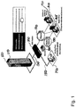
- FIG 1 illustrates a known configuration for a digital keyboard, video and mouse (KVM) switch 100, such as a DSR 1020, 2020, 4020 or 8020 available from Avocent Corp., the assignee of the present application.
- the KVM switch 100 is illustratively connected to a computer 110 (e.g., a blade server) in a rack housing 120 via a communications medium 130, such as at least one CAT-5 cable.
- the KVM switch 100 may alternatively be coupled to a stand-alone computer (not shown) using the same type of communications medium 130.
- a user such as a system administrator, can control the computer 110 utilizing a series of human interfaces.
- the first interface that can control the computer 110 is a direct-link keyboard/video/mouse configuration 140 that is directly connected to corresponding keyboard, video and mouse ports (see Fig. 2 ) of the KVM switch 100.
- the user is typically within normal cable lengths of the KVM switch 100.
- the KVM ports of the KVM switch 100 may alternatively be coupled to another KVM switch as part of a cascade of KVM switches.
- the second interface that can control the computer 110 is a control computer 160 that is connected to the KVM switch 100 indirectly via a network 170, such as an Ethernet-based packet switched network.
- the control computer 160 may also connect to the KVM switch 100 via a telephone network 180 utilizing at least one modem 185.
- the control computer 160 is a general purpose computer (such as might be running one of the Microsoft WindowsTM Operating Systems (e.g., XP, 2000, ME, 98 or 95)) that also includes a control program for interacting with the KVM switch 100.
- the control program may include the DSViewTM family of software (e.g., DSView 2 and DSView 3) available from Avocent Corp. Using such a control program, the user is able to utilize a local input device 190 (e.g., a mouse, a trackball or a tablet) to interact with the video being received from the remote computer 110.
- a local input device 190 e.g., a mouse, a trackball or a
- the third interface that can be used to control the computer 110 is a browser-based computer 165 which utilizes a web-browser (e.g., Internet ExplorerTM by Microsoft or Mozilla FirefoxTM).
- the browser-based computer 165 may connect to the KVM switch 100 via either a network 170 or via a telephone network 180 utilizing at least one modem 185.
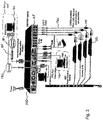
- FIG. 2 illustrates in greater detail the connections of a known KVM switch 100.
- the KVM switch 100 connects a user (e.g., via a direct-link keyboard/video/mouse configuration 140, or at either control computer 160 or browser-based computer 165) to up to thirty-two remote computers 110 via communications media 130 connected to the remote network ports 135.
- a circuit such as a DSRIQ 115
- the digital signals keyboard and mouse
- the video signals are placed on separate twisted pair wires (one R, G, B signal per wire pair) within a single cable.
- DSRIQs available from Avocent include DSRIQ-PS2, -PS2L, -USB, -USB2 and -VSN.
- a cursor that provides the most rapid feedback to the user is the cursor that is generated at the local computer, i.e., at control computer 160.
- the movement of local cursor may not, and often does not, correspond to how the cursor of the remote computer 110 reacts to the same movements, depending on at least one configurable movement parameter.
- the MouseSpeed registry entry will be non-zero, such as 1 or 2.
- the MouseSpeed entry is set to one ("1").
- the MouseThreshold1 and MouseThreshold2 entries are set to 7 and 0, respectively.
- the MouseSpeed can be set to two ("2") with corresponding values for MouseThreshold1 and MouseThreshold2 in order to enable medium and high acceleration, respectively.
- the threshold entries indicate at what level of movement the movement is accelerated. "MouseThreshold2" specifies a mouse speed that triggers accelerated cursor movement. If, within the interval between mouse interrupts, the mouse moves by more than the number of units specified in the value of this entry, the system can accelerate the cursor. When accelerated, the cursor moves more than one unit for each one-unit movement of the mouse. The amount of acceleration depends on the value of MouseSpeed. If the value of MouseSpeed is 1 or 2, cursor speed doubles when the mouse speed reaches MouseThreshold1. If the value of MouseSpeed is 2, cursor speed quadruples when the mouse speed reaches MouseThreshold2.
- MouseSensitivity is set via the "Pointer Speed" setting on the Mouse Control Panel GUI. If MouseSensitivity is set to a value of zero (the lowest value which can be set through the Mouse Control Panel GUI is one - setting it to zero requires editing or programmatic manipulation of the registry), and "Enhance Pointer Precision" is not checked, then under Windows XP the registry entries cause the cursor to move in a manner identical to Windows 2000. If MouseSensitivity is set to a non-zero value, and if "Enhance Pointer Precision” is not checked, then MouseSensitivity acts as a multiplier on mouse input. When “Enhance Pointer Precision” is checked the cursor moves in a manner as described in Pointer Ballistics for Windows XP.
- xset takes two parameters: the acceleration value and the threshold value. With those two settings the mouse moves on a 1:1 basis until the threshold value is reached at which point it then moves by the multiple specified by the acceleration value.
- xset command into a file that gets run at startup, such as /etc/rc.local the mouse settings can be set each time Linux is started.
- US Patent Publication No. 2002/083098 describes a cursor position calculator utilizing an onMouseMove event handler to obtain the position of a mouse cursor that is used for remote pointer synchronization between two collaborating systems, potentially utilizing different browsers.
- the synchronization does not, however, utilize predictive position-independent movement calculations.
- US Patent Publication No. 2004/0215743 describes prompting a user to synchronize the client mouse and the host mouse if it detects that they are no longer synchronized and automatically synchronizing periodically. The synchronization does not, however, utilize predictive position-independent movement calculations.
- US Patent Publication No. 2005/0007344 describes utilizing absolute mouse cursor positioning to synchronize a virtual mouse cursor with a physical mouse cursor. The synchronization does not, however, utilize predictive position-independent movement calculations.
- US Patent Publication No. 2005/0104852 describes an emulation device generating pointer position data representing a position of a second pointing device based on first pointer position data received from a first pointing device. It does not, however, describe synchronization utilizing predictive position-independent movement calculations.
- One embodiment of the present invention is achieved by utilizing a KVM switch that generates the first and second movement information, described above, in order to simulate the movement of an input device, such as a mouse.
- a KVM switch By utilizing the KVM switch to perform the movement, a user does not have to be trained to properly move the mouse in the fashion that enables the configurable movement parameter(s) to be determined.
- control computer executes the software described above as having been run on the KVM switch to determine the value(s) of the configurable movement parameter(s).
- the KVM switch can provide to the user a series of prompts (e.g., audio or visual) that specify how the input device is to be moved, and when, so that the user can move the input device in a fashion that will enable the KVM switch to determine the value(s) of the configurable movement parameter(s).
- a series of prompts e.g., audio or visual
- the methodology of the present invention can be divided into two general portions: (1) determining a shape of the cursor on the remote system and (2) determining how that cursor moves under various conditions which are effected by the at least one configurable movement parameter set on the remote computer.
- the user identifies (e.g., from a menu or a series of pictures or via a keyboard selection) the shape of a cursor where the cursor on the remote machine is known a priori to be one of the shapes presented to or selectable by the user.
- a user may identify the cursor (e.g., by drawing a square, circle or other shape around it) so that the shape of the cursor need not be known a priori.
- the shape of the cursor is automatically determined, e.g., as shown in Figure 3 .
- the shape of the cursor is determined by a procedure starting with step 300 and ending with step 380.
- the cursor of the input device e.g., a mouse, a trackball, a graphics tablet or similar device
- the cursor of the input device is moved to a known location.
- a location may be selected a priori (e.g., it is always the upper left-hand corner of the display), or it may be determined at run-time (e.g., by determining a seemingly least obstructed or cluttered area).
- a location that appears most like a solid color or other background image is selected by capturing and storing a frame of video and processing the frame.
- One such method would be to determine a region with the smallest variation.
- a corner region as the variation between the position of the local cursor and the remote cursor may be reduced in the corners since the remote computer typically will not allow the cursor to move beyond the corners. If the region to which the cursor is to be moved is not at an extremity, then the cursor may be moved to the designated position in a fashion (e.g., slowly enough) that the configurable movement parameter does not effect the movement of the cursor. This may or may not require first moving the local and remote cursors to a known extremity to synchronize them and then moving the cursors towards the known location.
- control passes to step 320, where a sample of video is stored for an initial area surrounding the known location.
- Control passes to step 330 where the cursor is moved out of the initial area stored for the video sampling step of step 320.
- Control then passes to step 340 where the video image of the initial area is again stored, this time without the cursor being within the initial area.
- Step 350 then calculates the difference between the two images, e.g., by performing a subtraction or an exclusive-OR of the two images and determining where the image has changed.
- steps 310 to 340 can be reversed such that the video is first stored while the cursor is kept out of the initial area and then video of the initial area is subsequently stored after the cursor has been moved to the known location.
- Step 350 which calculates the difference between the two stored images would still obtain the shape of the cursor by reversing the order that the difference is calculated in or by reversing the result of the difference calculation.
- an entire video frame may be stored in steps 320 and 340 but the difference between the two stored images need only be processed in the portion of the frame corresponding to the initial area (i.e., the area where the cursor is moved in and out or out and in).
- Control then passes to step 360. If the method is configured to try to obtain the shape of the cursor in a single execution of steps 310 to 350, then the number of samples necessary is selected to be one and control passes from step 360 to step 370. However, if the number of samples to be obtained is more than one, then control would pass from step 360 to step 310 so that the process of steps 310 to 350 can be repeated.
- step 360 passes control to step 370 where the shape of the cursor is determined.
- the shapes of the differences determined by step 350 may be compared against a series of known cursor shapes, and if a high enough correlation exists, the shape of the cursor will be selected as being one of the predefined shapes.
- the shapes of the differences are averaged to produce an image (e.g., a bitmap) of the predicted shape of the cursor, such as when the cursor is a non-standard cursor.
- the cursor shape selection process ends with step 380.
- the initial area for which the video is stored or where the stored frame is processed need not be the same for each iteration of steps 320-340.
- the initial location may be the upper left-hand corner for the first iteration of steps 320-340, and then it may be the lower righthand corner for the second iteration of steeps 320-340.
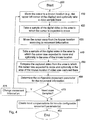
- step 380 the process of determining the correlation with the configurable movement parameter then continues with Figure 4 .
- the process starts with step 400 and ends with step 490.
- control passes to step 410 the cursor is moved to a known location (again, either selected a priori or at run time).
- the video around the initial cursor position optionally may be stored as well, e.g., in order to verify that the cursor has actually moved out as expected. However, as noted, it is optional.
- step 420 a sample of the video in the area to which the cursor is expected to move is stored. As would be appreciated by one of ordinary skill in the art, the order of the video storing of steps 410 and 420 may be reversed without departing from the scope of the invention.
- the cursor is then moved from its initial position according to movement information (either physical or virtual as described in greater detail below).
- step 440 video is stored from the area in which the cursor is expected to move and is optionally stored from the initial area.
- step 450 the stored video from steps 420 and 440 are examined to determine to where the cursor actually moved according to the movement information.
- the movement information is applied to each of a series of possible values to determine a series of predicted locations.
- the stored video is then compared to see to which of the predicted locations the cursor appears to have gone. This is done by removing the portions of the stored image(s) that have not changed and pattern matching with the shape of the cursor obtained in step 380. Based on the results of the comparison(s), the configurable movement parameter is determined in step 460.
- step 470 it is determined if more samples are needed. If so, control passes to step 475. If more samples are not needed, control passes to step 480. More than one sample may be needed in cases where the configurable movement parameter depends on multiple conditions or movements. More than one sample may also be necessary when there are multiple configurable movement conditions, e.g., an x-axis acceleration parameter and a y-axis acceleration parameter. Similarly, more than one sample may be necessary when one wishes to use a statistically significant number of samples to reduce the likelihood of making an incorrect correlation.
- the movement information need not be a single movement, e.g., from point A to point B, but instead may be a series of movements that take a known (relative or absolute) path but which are sufficient to distinguish one potential value of the at least one configurable movement parameter from another.
- the movement information may also include timing information about how long one or more movements along a path must take or in how many increments the movements must be made.
- the present invention may utilize movement information which describes a path including: a series of slow moving small movements followed by a series of faster moving movements of greater size and last followed by a series of even faster movements of even greater size.
- any time the cursor on the local computer is moved the amount it was moved will be programmatically modified to compensate for the acceleration that will occur on the target system. Movements of 1 unit are typically not accelerated since that would preclude fine movements, so multiple movements of 1 unit timed to the target's known update rate can be done. Unfortunately, the update rate at which commands can be sent to the target is relatively slow so 1 unit movements should not be continuously used, unless update rate command speed processing can be improved.
- characteristics i.e., characteristics
- the system and method receive a single movement and convert the movement into plural movements which are sent to the remote computer, wherein at least two of the plural movements will be modified on the remote computer using different translations.
- the two cursors will stay synchronized.
- the user may move the cursor on the local computer and have confidence that the cursor on the remote system will be moved to the exact same location.
- the local computer may still have to ensure that input device movements are only translated and sent to the remote computer when the cursor movement is actually within the local computer's image of the remote computer. For example, if the local computer is able to show the remote computer's video image in a window that takes up less than the full screen of the local computer, then only those movements within the window are translated and sent to the remote computer. However, this can be done by determining when the cursor on the local computer enters and leaves the window corresponding to the image of the remote computer.
- FIG. 5 and 6 two simulated screenshots illustrate the process of Figure 4 at a high-level.
- Figures 5 and 6 assume that the method of Figure 3 detected that the shape of the cursor on the remote computer 110 is an arrow.
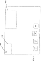
- the cursor 500 is then moved to a known location or initial region 510, illustrated as the upper left-hand corner of the screen.
- Figure 5 further illustrates that the size of the initial region 510 in which the cursor 500 starts need not be the same size (or shape) as the final region 520 in which the cursor 500 ends up.
- the present invention may elect to avoid those regions, by either automatic avoidance or via manual selection.
- Figure 6 illustrates how the method of the present invention moves the cursor 500 from the initial region 510 to the final region 520.
- Figure 6 also illustrates three predicted values for the final location of the cursor, depending on three possible values for the configurable movement parameter(s).
- the present invention detects that predicted cursors 600a and 600b at their respective locations are not as good as predicted cursor 600c at its location since predicted cursor 600c is the closest to the actual final location of cursor 500. While the illustrated example shows movement of the cursor in only a single direction, the present invention also includes movement in multiple directions.
- the present invention further includes performing fine adjustments to determine if there is a predicted cursor that is close to the predicted locations.
- variations of each of the locations are selected (e.g., in either increasing or decreasing distances from the originally predicted positions) and comparisons are made to determine if the cursor 500 is located at one of these adjusted positions. For example, if one of the predicted positions was (600, 50), then the fine adjustment procedure may check at (600, 50) ⁇ (i,i) for increasing values of "i".
- the present invention upon not finding the cursor 500 near any of the predicted locations, can additionally begin a comparison in a larger, modified final region (not shown) or even for every pixel of the stored image.
- the present invention alternatively can also ask the user to identify where the cursor is.
- the present invention may utilize a confidence value that represents how much of the cursor must match before a predicted cursor 600 can be declared a match for the actual cursor 500.
- a confidence level can be set to values such as 95%, 90% or 85% and may depend on the noise in the video acquisition process.
- the actual shape of the cursor is not utilized. Rather the system and method of the present invention simply track locations where there are changes in small areas. If it is determined that changes before and after the cursor movement correspond to possible predicted movements, then the method and/or system or the user may determine that a match exists for the at least one configurable movement parameter.
- the present invention may utilize plural frames of stored video to detect candidate regions in which changes are occurring while there is no movement from the input device. Such changes may be detected by differences between stored frames. Regions with such changes may also be avoided. Alternatively, user input may be requested to identify suitable or unsuitable candidate regions for the initial and final regions 510 and 520.
- the system of the present invention may additionally include code or circuitry to block or queue incoming input device commands destined for the remote computer 110 that is currently being configured.
- the present invention may additionally include code or circuitry to detect when input device movement occurred during the candidate selection and simply discard frames stored during movement. The candidate region selection process could then restart once input device movement stopped.
- the present invention can be implemented in a variety of different embodiments.
- the invention is fully or substantially automatic.
- the method of determining the correlation between movement corresponding to an input device and a value of at least one configurable movement parameter is performed inside a KVM switch 100.
- one or both of the methods of Figures 3 and 4 are performed inside the KVM switch 100.
- the method may be executed at any of a number of times.
- the method for detecting the remote configurable movement parameter may occur the first time that a computer is connected to the KVM switch 100.
- the KVM switch 100 is notified that the setting(s) of a new remote computer 110 is/are to be determined.
- the KVM switch 100 can begin the process of determining the at least one configurable movement parameter by generating movement information representing virtual input device movement. That is, the KVM switch 100 generates movement information that would be the same as what the input device would generate to move the cursor along the path(s) that is/are desired for step 430 of Figure 4 .
- the KVM switch 100 may further control the timing of the movements, if necessary, as well as the size of each movement in order to achieve the desired cursor motion.
- the KVM switch 100 will also generate movement information to move the cursor along multiple paths or at multiple speeds if necessary to determine each of the at least one configurable movement parameters.
- the KVM switch 100 may then store the value of the determined parameter in the memory (see 720 of Figure 7 ) of the KVM switch 100 so that the determination process need not be repeated when the user switches the KVM switch 100 to another remote computer (not shown) and then back to the remote computer 110 for which the parameter(s) was/were already determined.
- the KVM switch 100 freezes or blanks the video displayed to the user so that the user is not confused to see the cursor of the input device moving without the user actually moving the input device.
- the KVM switch 100 may also (1) display a message to the user that identifies the ongoing process and/or (2) disable or queue further input from the input device until the determination process is complete.
- the user may see the ongoing process, optionally with a message overlaid over the original video. Again the input from the input device may be disabled or queued.
- the method of the present invention may be re-run subsequently to determine a new value of the parameter.
- the re-running may be triggered through the use of a hot-key, a menu item, a selectable mouse movement pattern, a stand-alone program or any other means by which a command may be sent to the KVM switch 100 which would reinitiate the determination process.
- the determination process may be run each time that the KVM switch 100 switches to display a video output of a remote computer 110 or periodically (e.g., once a day when the KVM switch 100 first switches to the remote computer 110 for the day/period or at other times triggered by a timer (see 710 of Figure 7 )).
- the present invention may also include the ability to specify, e.g., via an on-screen display, what type of computer the remote computer 110 is such that the configurable movement parameter will be (initially) assumed to be the same for all such computers of that type.
- the type of operating system of the remote computer 110 may be specified so that the system does not bother using predicted values which are incompatible or unsupported by the remote computer 110.
- each remote computer 110 may be provided to the KVM switch 100 such that the KVM switch 100 can query a remote information source (e.g., a database) which contains the current or last known value of the configurable movement parameter.
- a remote information source e.g., a database
- the KVM switch 100 would also store the value of the configurable movement parameter(s) in the remote database after they are determined.
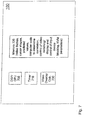
- FIG. 7 illustrates an exemplary which has been modified to include computer code and/or circuitry for implementing the method of the present invention.
- the KVM switch 100 includes a DSP/CPU 705 for performing the calculations of the method described above.
- the DSP / CPU 705 may be either a DSP, or a CPU or both, and may be either dedicated to the correlation calculation or shared with other functions that need to be performed inside the KVM switch 100, such as controlling the functions normally found within the DSR family (e.g., DSR 1020, 2020, 4020 and 8020) of products.
- the illustrated KVM switch 100 further includes a timer for periodically triggering the correlation process when the KVM switch 100 is so configured.
- the computer code may include, but is not limited to, code to determine the cursor shape, code to perform the correlation (including code to autonomously generate the movement information), code to control switching of video and/or display depending on what, if anything, a user is to see during a correlation or cursor determination process.
- the memory 720 may also include code to block or queue input from the input device as described above.
- the illustrated KVM switch 100 may further include a video overlay circuit 730 if such a circuit is needed to generate overlaid video.
- the KVM switch 100 performs configuration of the remote computer 110 while the user is interacting with a second remote computer (not shown). That is, the KVM switch 100 is autonomously performing the correlation of the present invention, including generating and transmitting movement information to a first computer and receiving back video from the first computer, while simultaneously sending to the user video from a second computer.
- the control computer 160 identifies to the KVM switch 100 which regions the KVM switch 100 should use for initial and final regions 510 and 520. Alternatively, the control computer 160 identifies to the KVM switch 100 what the shape of the cursor is such that the KVM switch 100 does not have to perform that calculation.
- the video from remote computer 110 is received by and analyzed by the control computer 160 to determine the changes in the video as a result of the virtual or simulated movements of the input device under the control of the KVM switch 100.
- the control computer 160 is configured to send to the remote computer 110 the movement information representing movements along the path(s) necessary to determine the at least one configurable movement parameter.
- the above-described software or circuitry of the control computer 160 used to generate the movement information is replaced with software or circuitry to prompt the user to perform the movements of the cursor as necessary to determine the at least one configurable movement parameter.
- Such prompts may be audio or visual or both.
- the software of control computer 160 can display a starting location and an ending location between which the cursor should be moved. In such a configuration, the software or circuitry can verify that the local cursor is moved as instructed and/or as necessary and may restart the movement process if not.
- the present invention may avoid the use of graphical pattern matching and replace it with user input.
- a screen such as shown in Figure 6 is presented to the user after the movement information (generated by any one of the KVM switch 100, the control computer 160 or the user) is sent to the remote computer 110.
- the user After being presented with such a screen showing each of the predicted cursor locations, the user would identify to the KVM switch 100 or the control computer 160 which of the predicted cursor positions was the closest, and the predicted value(s) used to generate that closest position would be stored as the configurable movement parameter.
- Such a user-based feedback process can be repeated a number of times to obtain further refinements or to make sure the proper value is selected.
- the present invention may provide direct control over which of the possible values is expected to be the configurable movement parameter.
- the user informs the KVM switch 100 or the control computer 160 which of the candidate values to use, and the KVM switch 100 or the control computer 160 begins providing the correction associated with that candidate value.
- the user can determine if the local and remote cursors are losing synchronization. If so, the user can elect to use a different candidate value.
- the system i.e., KVM switch 100 or the control computer 160
- the user would then resynchronize the local and remote cursors (e.g., by moving them both to a known location), and then the system would begin providing the correction associated with that new candidate value. The user could repeat this process until he/she had selected the candidate value which provided the best synchronization.
- the user interface to the system i.e., KVM switch 100 or the control computer 160
- the method is performed without adding any additional software to the remote computer such that the process is as unobtrusive and/or system independent as possible.
- a computer program product includes a computer readable medium with instructions embedded therein for causing a processor (CPU, GPU, DSP or configurable processor), acting as a controller, to perform the method(s) described above.
- a controller circuit coordinates and/or performs the method steps of the present invention.
Landscapes
- Engineering & Computer Science (AREA)
- General Engineering & Computer Science (AREA)
- Theoretical Computer Science (AREA)
- Human Computer Interaction (AREA)
- Physics & Mathematics (AREA)
- General Physics & Mathematics (AREA)
- User Interface Of Digital Computer (AREA)
- Position Input By Displaying (AREA)
- Digital Computer Display Output (AREA)
Description
- The present invention relates to a method and system for correlating the movement of an input device at a first location with the movement of a cursor of a remote computer at a second location, remote from the first location, and, in one embodiment, to the correlation of the virtual movement of a mouse device at a keyboard, video and mouse (KVM) switch with at least one acceleration setting associated with the remote computer.
-
Figure 1 illustrates a known configuration for a digital keyboard, video and mouse (KVM)switch 100, such as a DSR 1020, 2020, 4020 or 8020 available from Avocent Corp., the assignee of the present application. TheKVM switch 100 is illustratively connected to a computer 110 (e.g., a blade server) in a rack housing 120 via a communications medium 130, such as at least one CAT-5 cable. TheKVM switch 100 may alternatively be coupled to a stand-alone computer (not shown) using the same type of communications medium 130. A user, such as a system administrator, can control thecomputer 110 utilizing a series of human interfaces. - The first interface that can control the
computer 110 is a direct-link keyboard/video/mouse configuration 140 that is directly connected to corresponding keyboard, video and mouse ports (seeFig. 2 ) of theKVM switch 100. In order to use the first interface, the user is typically within normal cable lengths of theKVM switch 100. Alternatively, the KVM ports of theKVM switch 100 may alternatively be coupled to another KVM switch as part of a cascade of KVM switches. - The second interface that can control the
computer 110 is acontrol computer 160 that is connected to theKVM switch 100 indirectly via anetwork 170, such as an Ethernet-based packet switched network. Thecontrol computer 160 may also connect to theKVM switch 100 via atelephone network 180 utilizing at least onemodem 185. Thecontrol computer 160 is a general purpose computer (such as might be running one of the Microsoft Windows™ Operating Systems (e.g., XP, 2000, ME, 98 or 95)) that also includes a control program for interacting with theKVM switch 100. The control program may include the DSView™ family of software (e.g., DSView 2 and DSView 3) available from Avocent Corp. Using such a control program, the user is able to utilize a local input device 190 (e.g., a mouse, a trackball or a tablet) to interact with the video being received from theremote computer 110. - The third interface that can be used to control the
computer 110 is a browser-basedcomputer 165 which utilizes a web-browser (e.g., Internet Explorer™ by Microsoft or Mozilla Firefox™). The browser-basedcomputer 165, like thecontrol computer 160, may connect to theKVM switch 100 via either anetwork 170 or via atelephone network 180 utilizing at least onemodem 185. -
Figure 2 illustrates in greater detail the connections of a knownKVM switch 100. In the illustrated embodiment, theKVM switch 100 connects a user (e.g., via a direct-link keyboard/video/mouse configuration 140, or at either controlcomputer 160 or browser-based computer 165) to up to thirty-tworemote computers 110 via communications media 130 connected to theremote network ports 135. Using a circuit such as a DSRIQ 115, the digital signals (keyboard and mouse) are combined into a single digital protocol for transmission across communications media 130, and the video signals are placed on separate twisted pair wires (one R, G, B signal per wire pair) within a single cable. Commercially available DSRIQs available from Avocent include DSRIQ-PS2, -PS2L, -USB, -USB2 and -VSN. - One problem associated with the above-noted configurations is that when a user of the
control computer 160 utilizes theinput device 190, a cursor that provides the most rapid feedback to the user is the cursor that is generated at the local computer, i.e., atcontrol computer 160. The movement of local cursor, however, may not, and often does not, correspond to how the cursor of theremote computer 110 reacts to the same movements, depending on at least one configurable movement parameter. - Under the Windows™ Operating System, it is possible to establish acceleration parameters that effect how the physical movement of an input device is converted into movement of the cursor on the display. In particular, registry entries (such as "MouseSpeed") can be created and subsequently read that control the acceleration of the mouse as it moves. Table I below illustrates the acceleration parameters that can be set under the Windows 2000 Operating System.
Table I Acceleration Setting on Mouse Control Panel GUI MouseSpeed registry entry MouseThrehold1 registry entry MouseThreshold2 registry entry None 0 0 0 Low 1 7 0 Medium 2 4 12 High 2 4 6 - According to Table I, when the MouseSpeed registry entry is set to a value of zero ("0"), no acceleration modifications are made to mouse movements. This corresponds to the setting normally set when using known KVM switches 100 to avoid the mismatch (or lack of synchronization) between the local cursor movement and the remote cursor movement. However, this setting can be reset by a user that is unfamiliar with the consequences, such that a mismatch occurs. Moreover, a
computer 110 to be connected to aKVM switch 100 may be factory set to have a non-zero value set for "MouseSpeed" such that there may be a mismatch even when thecomputer 110 is first connected to theKVM switch 100. - If acceleration is enabled, then the MouseSpeed registry entry will be non-zero, such as 1 or 2. When the
remote computer 110 is set to use Low Acceleration, then the MouseSpeed entry is set to one ("1"). Under that configuration, the MouseThreshold1 and MouseThreshold2 entries are set to 7 and 0, respectively. - Similarly, the MouseSpeed can be set to two ("2") with corresponding values for MouseThreshold1 and MouseThreshold2 in order to enable medium and high acceleration, respectively.
- The threshold entries indicate at what level of movement the movement is accelerated. "MouseThreshold2" specifies a mouse speed that triggers accelerated cursor movement. If, within the interval between mouse interrupts, the mouse moves by more than the number of units specified in the value of this entry, the system can accelerate the cursor. When accelerated, the cursor moves more than one unit for each one-unit movement of the mouse. The amount of acceleration depends on the value of MouseSpeed. If the value of MouseSpeed is 1 or 2, cursor speed doubles when the mouse speed reaches MouseThreshold1. If the value of MouseSpeed is 2, cursor speed quadruples when the mouse speed reaches MouseThreshold2.
- Under Windows XP, registry entries are identical to Windows 2000 with the addition of a MouseSensitivity entry. If "Enhance Pointer Precision" is checked in the Mouse Control Panel GUI values used for the registry entries are as shown in Table II.
Table II Enhance Pointer Precision MouseSpeed registry entry MouseThrehold1 registre entry MouseThreshold2 registry entry Not Checked 0 0 0 Checked 1 6 10 - MouseSensitivity is set via the "Pointer Speed" setting on the Mouse Control Panel GUI. If MouseSensitivity is set to a value of zero (the lowest value which can be set through the Mouse Control Panel GUI is one - setting it to zero requires editing or programmatic manipulation of the registry), and "Enhance Pointer Precision" is not checked, then under Windows XP the registry entries cause the cursor to move in a manner identical to Windows 2000. If MouseSensitivity is set to a non-zero value, and if "Enhance Pointer Precision" is not checked, then MouseSensitivity acts as a multiplier on mouse input. When "Enhance Pointer Precision" is checked the cursor moves in a manner as described in Pointer Ballistics for Windows XP.
- Under Windows NT, the MouseSpeed registry entries are set as described below in Table III.
Table III Speed Setting on Mouse Control Panel GUI MouseSpeed registry entry MouseThrehold1 registry entry MouseThreshold2 registry entry Slow (slider fully left) 0 0 0 Slider +1 tick mark Slider +1 tick mark from left 1 10 0 Slider +2 tick marks from left 1 7 0 Slider +3 tick marks from left 1 4 0 Slider +4 tick marks from left 2 4 12 Slider +5 tick marks from left 2 4 9 Fast (slider fully right) 2 4 6 - Under Linux, the user can set the mouse acceleration through a Linux utility called xset. xset takes two parameters: the acceleration value and the threshold value. With those two settings the mouse moves on a 1:1 basis until the threshold value is reached at which point it then moves by the multiple specified by the acceleration value. By putting the xset command into a file that gets run at startup, such as /etc/rc.local the mouse settings can be set each time Linux is started.
-
US Patent Publication No. 2002/083098 describes a cursor position calculator utilizing an onMouseMove event handler to obtain the position of a mouse cursor that is used for remote pointer synchronization between two collaborating systems, potentially utilizing different browsers. The synchronization does not, however, utilize predictive position-independent movement calculations. -
US Patent Publication No. 2004/0215743 describes prompting a user to synchronize the client mouse and the host mouse if it detects that they are no longer synchronized and automatically synchronizing periodically. The synchronization does not, however, utilize predictive position-independent movement calculations. -
US Patent Publication No. 2005/0007344 describes utilizing absolute mouse cursor positioning to synchronize a virtual mouse cursor with a physical mouse cursor. The synchronization does not, however, utilize predictive position-independent movement calculations. -
US Patent Publication No. 2005/0104852 describes an emulation device generating pointer position data representing a position of a second pointing device based on first pointer position data received from a first pointing device. It does not, however, describe synchronization utilizing predictive position-independent movement calculations. - It is an object of the present invention to detect a correlation of input device movements, sent from a first location, with at least one configurable movement parameter set on a remote computer at a second location remote from the first location, wherein the method includes: (a) sending first movement information from the first location to the remote computer at the second location, the first movement information corresponding to a first movement of the input device; (b) tracking a resulting movement of a cursor of the remote computer at the second location in response to the remote computer having received the first movement information and utilized the at least one configurable movement parameter; (c) calculating predicted movements utilizing at least two possible values for the at least one configurable movement parameter; and (d) determining which of the at least two possible values provides the predicted movement most closely matching the resulting movement of the cursor.
- One embodiment of the present invention is achieved by utilizing a KVM switch that generates the first and second movement information, described above, in order to simulate the movement of an input device, such as a mouse. By utilizing the KVM switch to perform the movement, a user does not have to be trained to properly move the mouse in the fashion that enables the configurable movement parameter(s) to be determined.
- In yet another embodiment, the control computer executes the software described above as having been run on the KVM switch to determine the value(s) of the configurable movement parameter(s).
- In an alternate embodiment, the KVM switch can provide to the user a series of prompts (e.g., audio or visual) that specify how the input device is to be moved, and when, so that the user can move the input device in a fashion that will enable the KVM switch to determine the value(s) of the configurable movement parameter(s).
- The following description, given with respect to the attached drawings, may be better understood with reference to the non-limiting examples of the drawings, wherein:
-
Figure 1 is a high-level diagram representing a known configuration for using a keyboard/video/mouse (KVM) switch; -
Figure 2 is a connection-level diagram representing various connections of a known KVM switch; -
Figure 3 is a flowchart showing a method of detecting a cursor shape as part of the present invention which may be incorporated into and performed by the KVM switches ofFigures 1 and2 or which may be incorporated into and performed by computers connected to the KVM switches ofFigures 1 and2 ; -
Figure 4 is a flowchart showing a method of detecting a correlation between movement of an input device and at least configurable movement parameter set on a remote computer according to the present invention; -
Figure 5 is a simulated screenshot showing a cursor in an initial area of a remote desktop with a second area designated as the area to which the cursor will ultimately be moved; -
Figure 6 is a simulated screenshot showing the remote desktop ofFigure 5 after the cursor has been moved according to the invention and with three predicted locations for the cursor according to three different predicted values for the at least one configurable movement parameter(s); and -
Figure 7 is a block diagram of an illustrative embodiment of a KVM switch according to the present invention. - As described herein, the methodology of the present invention can be divided into two general portions: (1) determining a shape of the cursor on the remote system and (2) determining how that cursor moves under various conditions which are effected by the at least one configurable movement parameter set on the remote computer. In the simplest configuration of the first portion, the user identifies (e.g., from a menu or a series of pictures or via a keyboard selection) the shape of a cursor where the cursor on the remote machine is known a priori to be one of the shapes presented to or selectable by the user. Alternatively, a user may identify the cursor (e.g., by drawing a square, circle or other shape around it) so that the shape of the cursor need not be known a priori.
- In a more complicated configuration of the first portion, the shape of the cursor is automatically determined, e.g., as shown in
Figure 3 . In the implementation ofFigure 3 , the shape of the cursor is determined by a procedure starting withstep 300 and ending withstep 380. When control passes to step 310, the cursor of the input device (e.g., a mouse, a trackball, a graphics tablet or similar device) is moved to a known location. Such a location may be selected a priori (e.g., it is always the upper left-hand corner of the display), or it may be determined at run-time (e.g., by determining a seemingly least obstructed or cluttered area). In the case of determining the location at run-time, a location that appears most like a solid color or other background image is selected by capturing and storing a frame of video and processing the frame. One such method would be to determine a region with the smallest variation. - It may be preferable to select a corner region as the variation between the position of the local cursor and the remote cursor may be reduced in the corners since the remote computer typically will not allow the cursor to move beyond the corners. If the region to which the cursor is to be moved is not at an extremity, then the cursor may be moved to the designated position in a fashion (e.g., slowly enough) that the configurable movement parameter does not effect the movement of the cursor. This may or may not require first moving the local and remote cursors to a known extremity to synchronize them and then moving the cursors towards the known location.
- Once the cursor has been moved to the known location, control then passes to step 320, where a sample of video is stored for an initial area surrounding the known location. Control then passes to step 330 where the cursor is moved out of the initial area stored for the video sampling step of
step 320. Control then passes to step 340 where the video image of the initial area is again stored, this time without the cursor being within the initial area. Step 350 then calculates the difference between the two images, e.g., by performing a subtraction or an exclusive-OR of the two images and determining where the image has changed. - As would be appreciated by one of ordinary skill in the art, steps 310 to 340 can be reversed such that the video is first stored while the cursor is kept out of the initial area and then video of the initial area is subsequently stored after the cursor has been moved to the known location. Step 350 which calculates the difference between the two stored images would still obtain the shape of the cursor by reversing the order that the difference is calculated in or by reversing the result of the difference calculation. As would also be evident to one of ordinary skill in the art, an entire video frame may be stored in
steps - Control then passes to step 360. If the method is configured to try to obtain the shape of the cursor in a single execution of
steps 310 to 350, then the number of samples necessary is selected to be one and control passes fromstep 360 to step 370. However, if the number of samples to be obtained is more than one, then control would pass fromstep 360 to step 310 so that the process ofsteps 310 to 350 can be repeated. - Once a sufficient number of samples have been taken, step 360 passes control to step 370 where the shape of the cursor is determined. In one embodiment, the shapes of the differences determined by
step 350 may be compared against a series of known cursor shapes, and if a high enough correlation exists, the shape of the cursor will be selected as being one of the predefined shapes. In an alternate embodiment, the shapes of the differences are averaged to produce an image (e.g., a bitmap) of the predicted shape of the cursor, such as when the cursor is a non-standard cursor. However, in all cases, after a cursor shape has been determined or selected, the cursor shape selection process ends withstep 380. - As would be appreciated by one of ordinary skill in the art, the initial area for which the video is stored or where the stored frame is processed need not be the same for each iteration of steps 320-340. For example, the initial location may be the upper left-hand corner for the first iteration of steps 320-340, and then it may be the lower righthand corner for the second iteration of steeps 320-340.
- Using the result of
step 380, the process of determining the correlation with the configurable movement parameter then continues withFigure 4 . The process starts withstep 400 and ends withstep 490. When control passes to step 410, the cursor is moved to a known location (again, either selected a priori or at run time). The video around the initial cursor position optionally may be stored as well, e.g., in order to verify that the cursor has actually moved out as expected. However, as noted, it is optional. Instep 420, a sample of the video in the area to which the cursor is expected to move is stored. As would be appreciated by one of ordinary skill in the art, the order of the video storing ofsteps step 430, the cursor is then moved from its initial position according to movement information (either physical or virtual as described in greater detail below). Instep 440, video is stored from the area in which the cursor is expected to move and is optionally stored from the initial area. - In
step 450, the stored video fromsteps step 380. Based on the results of the comparison(s), the configurable movement parameter is determined instep 460. - In
step 470, it is determined if more samples are needed. If so, control passes to step 475. If more samples are not needed, control passes to step 480. More than one sample may be needed in cases where the configurable movement parameter depends on multiple conditions or movements. More than one sample may also be necessary when there are multiple configurable movement conditions, e.g., an x-axis acceleration parameter and a y-axis acceleration parameter. Similarly, more than one sample may be necessary when one wishes to use a statistically significant number of samples to reduce the likelihood of making an incorrect correlation. - As would be appreciated by one of ordinary skill in the art, the movement information need not be a single movement, e.g., from point A to point B, but instead may be a series of movements that take a known (relative or absolute) path but which are sufficient to distinguish one potential value of the at least one configurable movement parameter from another. Moreover, the movement information may also include timing information about how long one or more movements along a path must take or in how many increments the movements must be made. For example, the present invention may utilize movement information which describes a path including: a series of slow moving small movements followed by a series of faster moving movements of greater size and last followed by a series of even faster movements of even greater size.
- In one such case, with reference to Table I above, with one movement of eight units it is possible to tell if no acceleration is turned on or if low acceleration is turned on (if those are the only possible values). In the case of no acceleration, the remote cursor would have moved eight units in response to the local eight unit move. However, in the case of low acceleration, the remote cursor would have moved sixteen units in response to the local eight unit move. Thus, by determining whether the movement was closer to eight or sixteen, the present invention can select the more appropriate configurable movement parameter.
- If more than just "none" and "low" accelerations are possible, then additional movements may be necessary to distinguish between the other possible values also. For example, by moving the cursor at least four units and less than six units, it can be determined if medium or high acceleration is on by seeing if the remote cursor's move is double the local cursor's move. If not, then the local cursor can be moved eight units at that point to see if low or no acceleration is turned on. If the 4 or 5 unit move reveals that medium or high acceleration is turned on, then the cursor can be moved six or more units but less than 12 units to see if the movement quadruples. If so, then "high" acceleration is turned on; otherwise "medium" acceleration is turned on.
- Once the acceleration rate of the cursor on the remote computer is known, any time the cursor on the local computer is moved the amount it was moved will be programmatically modified to compensate for the acceleration that will occur on the target system. Movements of 1 unit are typically not accelerated since that would preclude fine movements, so multiple movements of 1 unit timed to the target's known update rate can be done. Unfortunately, the update rate at which commands can be sent to the target is relatively slow so 1 unit movements should not be continuously used, unless update rate command speed processing can be improved.
- The method and system of the present invention receive movement information and, using the determined at least one configurable movement parameter, convert the movement information into a set of one or more substituted movements, potentially each with its own characteristic such that the position of the cursor on the remote system matches the position of the cursor on the local system. For example, if the input device moves 35 units on the local system and the mouse acceleration thresholds (i.e., characteristics) are set to MouseThreshold1=4 and MouseThreshold2=6, then the present invention would send a movement of 8, which would be quadrupled because it exceeds MouseThreshold2, and another movement of 3, which would not be doubled or quadrupled because it does not exceed either of the thresholds (characteristics). Together the two movements would produce a movement on the remote computer of 8*4 + 3 = 35 which is the same as the original movement, and thus the two mouse cursors stay in synchronization. Generally, when applicable, the system and method receive a single movement and convert the movement into plural movements which are sent to the remote computer, wherein at least two of the plural movements will be modified on the remote computer using different translations.
- Since the cursor on the local computer is moved a known amount, and the cursor on the remote system is moved the same amount through the use of the programmatic modification of the cursor movement amounts, then the two cursors (local and remote) will stay synchronized. By staying synchronized the user may move the cursor on the local computer and have confidence that the cursor on the remote system will be moved to the exact same location. (The local computer may still have to ensure that input device movements are only translated and sent to the remote computer when the cursor movement is actually within the local computer's image of the remote computer. For example, if the local computer is able to show the remote computer's video image in a window that takes up less than the full screen of the local computer, then only those movements within the window are translated and sent to the remote computer. However, this can be done by determining when the cursor on the local computer enters and leaves the window corresponding to the image of the remote computer.)
- Turning to
Figures 5 and6 , two simulated screenshots illustrate the process ofFigure 4 at a high-level.Figures 5 and6 assume that the method ofFigure 3 detected that the shape of the cursor on theremote computer 110 is an arrow. Thecursor 500 is then moved to a known location orinitial region 510, illustrated as the upper left-hand corner of the screen.Figure 5 further illustrates that the size of theinitial region 510 in which thecursor 500 starts need not be the same size (or shape) as thefinal region 520 in which thecursor 500 ends up. As can also be seen, there are locations on the remote desktop that include icons (illustrated as icons 1-4) which could make poorer candidates for theinitial region 510 orfinal region 520. Thus, the present invention may elect to avoid those regions, by either automatic avoidance or via manual selection. -
Figure 6 illustrates how the method of the present invention moves thecursor 500 from theinitial region 510 to thefinal region 520.Figure 6 also illustrates three predicted values for the final location of the cursor, depending on three possible values for the configurable movement parameter(s). By using graphical pattern matching, the present invention detects that predictedcursors cursor 500. While the illustrated example shows movement of the cursor in only a single direction, the present invention also includes movement in multiple directions. - As can be seen from
Figure 6 , it is possible that none of the predictedcursors 600a-600c actually align exactly with thecursor 500 in thefinal region 520. In such a case, the present invention further includes performing fine adjustments to determine if there is a predicted cursor that is close to the predicted locations. In an implementation of one such method, variations of each of the locations are selected (e.g., in either increasing or decreasing distances from the originally predicted positions) and comparisons are made to determine if thecursor 500 is located at one of these adjusted positions. For example, if one of the predicted positions was (600, 50), then the fine adjustment procedure may check at (600, 50) ±(i,i) for increasing values of "i". Starting at i=1, those positions would include (599, 49), (599, 50), (599, 51), (600, 49), (600, 51), (601,49), (601, 50), (601, 51). If ±(i,i) for i=1 failed to find a cursor match at any of the originally predicted locations, then the value of "i" would be reset to i=2 and the calculations repeated. The value of "i" would be increased up to a threshold at which point the system may determine that it does not know how to compensate for the change. - Alternatively, instead of staying within the
final region 520, the present invention, upon not finding thecursor 500 near any of the predicted locations, can additionally begin a comparison in a larger, modified final region (not shown) or even for every pixel of the stored image. The present invention alternatively can also ask the user to identify where the cursor is. - It is also possible that due to sampling errors when the image was created the
cursor 500 is not exactly the same shape as the determined cursor fromFigure 3 . In such a case, to avoid a detection failure, the present invention may utilize a confidence value that represents how much of the cursor must match before a predicted cursor 600 can be declared a match for theactual cursor 500. Such a confidence level can be set to values such as 95%, 90% or 85% and may depend on the noise in the video acquisition process. - In yet another embodiment of the present invention, the actual shape of the cursor is not utilized. Rather the system and method of the present invention simply track locations where there are changes in small areas. If it is determined that changes before and after the cursor movement correspond to possible predicted movements, then the method and/or system or the user may determine that a match exists for the at least one configurable movement parameter.
- When detecting initial and
final regions final regions - To ensure that movement of the input device does not interfere with the detection of suitable candidate regions, the system of the present invention may additionally include code or circuitry to block or queue incoming input device commands destined for the
remote computer 110 that is currently being configured. Alternatively, the present invention may additionally include code or circuitry to detect when input device movement occurred during the candidate selection and simply discard frames stored during movement. The candidate region selection process could then restart once input device movement stopped. - While described generally above, the present invention can be implemented in a variety of different embodiments. In a first embodiment, the invention is fully or substantially automatic. In this embodiment, the method of determining the correlation between movement corresponding to an input device and a value of at least one configurable movement parameter is performed inside a
KVM switch 100. In such an embodiment, one or both of the methods ofFigures 3 and4 are performed inside theKVM switch 100. - The method may be executed at any of a number of times. For example, the method for detecting the remote configurable movement parameter may occur the first time that a computer is connected to the
KVM switch 100. In such a configuration, theKVM switch 100 is notified that the setting(s) of a newremote computer 110 is/are to be determined. Once theremote computer 110 has booted to its configuration in which the cursor is to be tracked, theKVM switch 100 can begin the process of determining the at least one configurable movement parameter by generating movement information representing virtual input device movement. That is, theKVM switch 100 generates movement information that would be the same as what the input device would generate to move the cursor along the path(s) that is/are desired forstep 430 ofFigure 4 . TheKVM switch 100 may further control the timing of the movements, if necessary, as well as the size of each movement in order to achieve the desired cursor motion. TheKVM switch 100 will also generate movement information to move the cursor along multiple paths or at multiple speeds if necessary to determine each of the at least one configurable movement parameters. - The
KVM switch 100 may then store the value of the determined parameter in the memory (see 720 ofFigure 7 ) of theKVM switch 100 so that the determination process need not be repeated when the user switches theKVM switch 100 to another remote computer (not shown) and then back to theremote computer 110 for which the parameter(s) was/were already determined. - In one implementation of such a method being performed by a
KVM switch 100, theKVM switch 100 freezes or blanks the video displayed to the user so that the user is not confused to see the cursor of the input device moving without the user actually moving the input device. In such an embodiment, theKVM switch 100 may also (1) display a message to the user that identifies the ongoing process and/or (2) disable or queue further input from the input device until the determination process is complete. Alternatively, the user may see the ongoing process, optionally with a message overlaid over the original video. Again the input from the input device may be disabled or queued. - Given that a user may select to reconfigure the at least one movement parameter after the value of the parameter has been stored in the memory of the
KVM switch 100, the method of the present invention may be re-run subsequently to determine a new value of the parameter. The re-running may be triggered through the use of a hot-key, a menu item, a selectable mouse movement pattern, a stand-alone program or any other means by which a command may be sent to theKVM switch 100 which would reinitiate the determination process. In yet further embodiments, the determination process may be run each time that theKVM switch 100 switches to display a video output of aremote computer 110 or periodically (e.g., once a day when theKVM switch 100 first switches to theremote computer 110 for the day/period or at other times triggered by a timer (see 710 ofFigure 7 )). - The present invention may also include the ability to specify, e.g., via an on-screen display, what type of computer the
remote computer 110 is such that the configurable movement parameter will be (initially) assumed to be the same for all such computers of that type. Alternatively, the type of operating system of theremote computer 110 may be specified so that the system does not bother using predicted values which are incompatible or unsupported by theremote computer 110. - Alternatively, the identity of each
remote computer 110 may be provided to theKVM switch 100 such that theKVM switch 100 can query a remote information source (e.g., a database) which contains the current or last known value of the configurable movement parameter. Such an embodiment may be especially helpful in disaster recovery environments so that the determined values can be quickly recovered in case of a failure of theKVM switch 100. In such an embodiment, theKVM switch 100 would also store the value of the configurable movement parameter(s) in the remote database after they are determined. -
Figure 7 illustrates an exemplary which has been modified to include computer code and/or circuitry for implementing the method of the present invention. TheKVM switch 100 includes a DSP/CPU 705 for performing the calculations of the method described above. The DSP/CPU 705 may be either a DSP, or a CPU or both, and may be either dedicated to the correlation calculation or shared with other functions that need to be performed inside theKVM switch 100, such as controlling the functions normally found within the DSR family (e.g., DSR 1020, 2020, 4020 and 8020) of products. The illustratedKVM switch 100 further includes a timer for periodically triggering the correlation process when theKVM switch 100 is so configured. It also includes amemory 720 for holding received video frames, cursor shapes (both predicted as well as a library of known shapes), predicted values, KVM configuration values (e.g., the names of remote computers and their determined configurable movement parameters, if known) and computer code. The computer code may include, but is not limited to, code to determine the cursor shape, code to perform the correlation (including code to autonomously generate the movement information), code to control switching of video and/or display depending on what, if anything, a user is to see during a correlation or cursor determination process. Thememory 720 may also include code to block or queue input from the input device as described above. The illustratedKVM switch 100 may further include avideo overlay circuit 730 if such a circuit is needed to generate overlaid video. - In yet a further embodiment, the
KVM switch 100 performs configuration of theremote computer 110 while the user is interacting with a second remote computer (not shown). That is, theKVM switch 100 is autonomously performing the correlation of the present invention, including generating and transmitting movement information to a first computer and receiving back video from the first computer, while simultaneously sending to the user video from a second computer. - In an alterative configuration for the present invention, at least a portion of the above-described functionality is moved from being implemented on the
KVM switch 100 to being implemented on the local computer. In one such configuration, thecontrol computer 160 identifies to theKVM switch 100 which regions theKVM switch 100 should use for initial andfinal regions control computer 160 identifies to theKVM switch 100 what the shape of the cursor is such that theKVM switch 100 does not have to perform that calculation. - In yet another embodiment, the video from
remote computer 110 is received by and analyzed by thecontrol computer 160 to determine the changes in the video as a result of the virtual or simulated movements of the input device under the control of theKVM switch 100. In a further embodiment of the present invention, thecontrol computer 160 is configured to send to theremote computer 110 the movement information representing movements along the path(s) necessary to determine the at least one configurable movement parameter. - In a more user-centric embodiment, the above-described software or circuitry of the
control computer 160 used to generate the movement information is replaced with software or circuitry to prompt the user to perform the movements of the cursor as necessary to determine the at least one configurable movement parameter. Such prompts may be audio or visual or both. For example, the software ofcontrol computer 160 can display a starting location and an ending location between which the cursor should be moved. In such a configuration, the software or circuitry can verify that the local cursor is moved as instructed and/or as necessary and may restart the movement process if not. - In another user-centric embodiment, the present invention may avoid the use of graphical pattern matching and replace it with user input. In such an embodiment, a screen such as shown in
Figure 6 is presented to the user after the movement information (generated by any one of theKVM switch 100, thecontrol computer 160 or the user) is sent to theremote computer 110. After being presented with such a screen showing each of the predicted cursor locations, the user would identify to theKVM switch 100 or thecontrol computer 160 which of the predicted cursor positions was the closest, and the predicted value(s) used to generate that closest position would be stored as the configurable movement parameter. Such a user-based feedback process can be repeated a number of times to obtain further refinements or to make sure the proper value is selected. - In another user-centric embodiment, the present invention may provide direct control over which of the possible values is expected to be the configurable movement parameter. In such an embodiment, the user informs the
KVM switch 100 or thecontrol computer 160 which of the candidate values to use, and theKVM switch 100 or thecontrol computer 160 begins providing the correction associated with that candidate value. As the user moves the cursor around, the user can determine if the local and remote cursors are losing synchronization. If so, the user can elect to use a different candidate value. The system (i.e.,KVM switch 100 or the control computer 160) or the user would then resynchronize the local and remote cursors (e.g., by moving them both to a known location), and then the system would begin providing the correction associated with that new candidate value. The user could repeat this process until he/she had selected the candidate value which provided the best synchronization. - The above description has been provided based on the assumption that the configurable movement parameters to be selected from were known a priori. However, future versions of operating systems may provide alternate values for the parameters of Tables I-III above. As a result, the
KVM switch 100 and thecontrol computer 160 may be equipped with the ability to receive updates of those tables, either from local or remote sources. Moreover, their software may be created to include the ability to "fine tune" parameters in the tables or create new table entries. In such an embodiment, the user interface to the system (i.e.,KVM switch 100 or the control computer 160) would include menus or hot-keys to (1) select which of the various entries in the tables are to be updated and (2) adjust (e.g., increment or decrement) the values in the selected entries such that the new or updated entries can be used as predicted values. - In at least one embodiment of the present invention, the method is performed without adding any additional software to the remote computer such that the process is as unobtrusive and/or system independent as possible.
- While the method above has been described as a method, performed in a KVM switch or on a computer, the functionality of the method can be implemented in software (either operating at a single location or in a distributed fashion), in hardware (e.g., in an ASIC, FPGA, printed circuit-board), and in a combination of any of the above. In a computer-implemented method, a computer program product includes a computer readable medium with instructions embedded therein for causing a processor (CPU, GPU, DSP or configurable processor), acting as a controller, to perform the method(s) described above. In a hardware-based implementation, a controller circuit coordinates and/or performs the method steps of the present invention.
- While the above description has been given with respect to particular examples, one of ordinary skill in the art will appreciate that other variations are possible which would still fall within the scope of the appended claims.
Claims (20)
- A method of detecting a correlation of input device movements, sent from a first location (140, 160, 165), with at least one configurable movement parameter set on a remote computer (110) at a second location remote from the first location, the method comprising:a transmitter transmitting first movement information from the first location to the remote computer at the second location, the first movement information corresponding to a first movement of the input device; a memory storing a resulting movement of a cursor (500) of the remote computer at the second location in response to the remote computer having received the first movement information and utilized the at least one configurable movement parameter; a controller calculating predicted movements (600a, 600b, 600c) utilizing at least two possible values for the at least one configurable movement parameter; and
the controller determining which of the at least two possible values provides the predicted movement most closely matching the resulting movement of the cursor. - The method of detecting as claimed in claim 1, wherein the at least one movement parameter is an acceleration parameter.
- The method of detecting as claimed in claim 2, wherein the acceleration parameter comprises a registry entry.
- The method of detecting as claimed in claim 3, wherein the registry entry is a MouseSpeed registry entry.
- The method of detecting as claimed in claim 1, wherein the method is performed at a keyboard/video/mouse (KVM) switch.
- The method of detecting as claimed in claim 5, wherein the steps of sending the first and second movement information comprises:generating the first and second movement information internally to the KVM switch without requiring physical movement of the input device.
- The method of detecting as claimed in claim 5, further comprising:receiving a command frown at least one of a keyboard and a mouse local to a user; andtriggering the KVM switch to perform the sending, tracking, calculating and determining steps in response to the received command.
- The method of detecting as claimed in claim 7, wherein the command comprises a hot-key.
- The method of detecting as claimed in claim 7, wherein the command is triggered by the selection of a menu item.
- The method of detecting as claimed in claim 7, wherein the command comprises a predetermined input device movement.
- The method of detecting as claimed in claim 1, wherein the steps of sending, tracking, calculating and determining are repeated more than once to reduce errors based on unexpected changes in video output of the remote computer
- The method of detecting as claimed in claim 1, further comprising determining a shape of a cursor as displayed on the remote computer, wherein the step of tracking the resulting movement comprises tracking a resulting movement of the cursor having the determined shape.
- The method of detecting as claimed in claim 12, wherein determining the shape of the cursor comprises performing a computer-based pattern matching operation.
- The method of detecting as claimed in claim 12, wherein determining the shape of the cursor comprises requesting a user to select a cursor shape from a library of cursor shapes.
- The method of detecting as claimed in claim 5, wherein the KVM switch performs the determining step for the remote computer while displaying to a user the video output of a computer other than the remote computer.
- The method of detecting as claimed in claim 5, wherein the KVM switch performs the determining step for the remote computer while displaying to a user a frozen video image of the remote computer so that movements of the cursor on the remote computer are not seen.
- The method of detecting as claimed in claim 1, further comprising applying a compensation to subsequent movement information to cause a local cursor to remain synchronized with a remote cursor of the remote computer which is utilizing the at least one configurable movement parameter.
- The method of detecting as claimed in claim 1, wherein the calculating predicted movements utilizing at least two possible values for the at least one configurable movement parameter comprises displaying to a user cursor positions indicative of the predicted movements when utilizing the at least two possible values for the at least one configurable movement parameter
- The method of detecting as claimed in claim 1, further comprising:sending second movement information from the first location to the remote computer at the second location, the second movement information corresponding to a second movement of the input device;tracking a resulting second movement of the cursor of the remote computer at the second location in response to the remote computer having received the second movement information and utilized a second parameter of the at least one configurable movement parameter;calculating predicted movement utilizing at least two possible values for the second parameter of the at least one configurable movement parameter; anddetermining which of the at least two possible values for the second parameter of the at least one configurable movement parameter provides the predicted movement most closely matching the resulting second movement of the cursor.
- A system comprising:a movement generator for generating first movement information corresponding to a movement of the input device;a transmitter for transmitting the first movement information from the first location (140, 160, 165) to the remote computer (110) at the second location;a memory for storing a resulting movement of a cursor (500) of the remote computer at the second location in response to the remote computer having received the first movement information and utilized the at least one configurable movement parameter; anda controller for (i) calculating predicted movements (600a, 600b, 600c) utilizing at least two possible values for the at least one configurable movement parameter and (ii) determining which of the at least two possible values provides the predicted movement most closely matching the resulting movement of the cursor.
Applications Claiming Priority (2)
| Application Number | Priority Date | Filing Date | Title |
|---|---|---|---|
| US11/250,406 US8319728B2 (en) | 2005-10-17 | 2005-10-17 | Input-device movement to cursor movement correlator |
| PCT/US2006/021181 WO2007046879A2 (en) | 2005-10-17 | 2006-05-30 | Input-device movement to cursor movement correlator |
Publications (3)
| Publication Number | Publication Date |
|---|---|
| EP1949207A2 EP1949207A2 (en) | 2008-07-30 |
| EP1949207A4 EP1949207A4 (en) | 2012-12-12 |
| EP1949207B1 true EP1949207B1 (en) | 2018-04-18 |
Family
ID=37947737
Family Applications (1)
| Application Number | Title | Priority Date | Filing Date |
|---|---|---|---|
| EP06771772.8A Active EP1949207B1 (en) | 2005-10-17 | 2006-05-30 | Input-device movement to cursor movement correlator |
Country Status (7)
| Country | Link |
|---|---|
| US (1) | US8319728B2 (en) |
| EP (1) | EP1949207B1 (en) |
| CA (1) | CA2626223A1 (en) |
| IL (1) | IL190922A (en) |
| MY (1) | MY140415A (en) |
| TW (1) | TW200717290A (en) |
| WO (1) | WO2007046879A2 (en) |
Families Citing this family (28)
| Publication number | Priority date | Publication date | Assignee | Title |
|---|---|---|---|---|
| US20060085253A1 (en) * | 2004-10-18 | 2006-04-20 | Matthew Mengerink | Method and system to utilize a user network within a network-based commerce platform |
| US20070200858A1 (en) * | 2006-02-28 | 2007-08-30 | Aten International Co., Ltd | KVM switch and a computer switching method |
| US8706560B2 (en) | 2011-07-27 | 2014-04-22 | Ebay Inc. | Community based network shopping |
| TWI313820B (en) * | 2006-09-08 | 2009-08-21 | Quanta Comp Inc | Method for operating host in hot key way in certralized computer system |
| US8373655B2 (en) * | 2007-01-05 | 2013-02-12 | Apple Inc. | Adaptive acceleration of mouse cursor |
| US7913178B2 (en) | 2007-01-31 | 2011-03-22 | Ebay Inc. | Method and system for collaborative and private sessions |
| US9024878B2 (en) * | 2007-02-16 | 2015-05-05 | Emulex Corporation | Hardware cursor snooping |
| US8214452B2 (en) * | 2007-07-30 | 2012-07-03 | Hewlett-Packard Development Company, L.P. | Monitoring of windows on computers |
| US20090172199A1 (en) * | 2007-12-28 | 2009-07-02 | Aten International Co., Ltd. | Method and system for calibrating response of pointer with respect to mouse |
| US9071843B2 (en) * | 2009-02-26 | 2015-06-30 | Microsoft Technology Licensing, Llc | RDP bitmap hash acceleration using SIMD instructions |
| US8954538B2 (en) * | 2009-11-17 | 2015-02-10 | Broadcom Corporation | Method and system for reducing latency for interactive content for complete internet anywhere |
| US9292161B2 (en) * | 2010-03-24 | 2016-03-22 | Microsoft Technology Licensing, Llc | Pointer tool with touch-enabled precise placement |
| US11012480B2 (en) * | 2010-09-13 | 2021-05-18 | Jeffrey W. Mankoff | Modifying signal associations in complex computing networks |
| US12328346B2 (en) | 2010-09-13 | 2025-06-10 | Jeffrey W. Mankoff | Modifying signal associations in complex computing networks |
| JP5259683B2 (en) * | 2010-11-19 | 2013-08-07 | 株式会社東芝 | Server apparatus and program |
| US9317196B2 (en) | 2011-08-10 | 2016-04-19 | Microsoft Technology Licensing, Llc | Automatic zooming for text selection/cursor placement |
| US9335910B2 (en) * | 2012-04-23 | 2016-05-10 | Tandem Diabetes Care, Inc. | System and method for reduction of inadvertent activation of medical device during manipulation |
| US9292108B2 (en) | 2012-06-28 | 2016-03-22 | Dell Products Lp | Systems and methods for remote mouse pointer management |
| GB2518206B (en) * | 2013-09-13 | 2021-03-31 | Realvnc Ltd | System and method for remote computer control |
| US10122585B2 (en) * | 2014-03-06 | 2018-11-06 | Dell Products, Lp | System and method for providing U-space aligned intelligent VLAN and port mapping |
| KR102329124B1 (en) * | 2015-01-05 | 2021-11-19 | 삼성전자주식회사 | Image display apparatus and method for displaying image |
| WO2016179436A1 (en) * | 2015-05-05 | 2016-11-10 | Colorado Code Craft Patent Holdco Llc | Ultra-low latency remote application access |
| US11883202B2 (en) | 2015-09-22 | 2024-01-30 | Medtronic, Inc. | System and method for interacting with an implantable medical device |
| US10307600B2 (en) | 2015-09-22 | 2019-06-04 | Medtronic, Inc. | System and method for interacting with an implantable medical device |
| US11768545B2 (en) | 2017-04-05 | 2023-09-26 | Fibernet Ltd. | Secured KVM switching device with unidirectional communications |
| IL265789B2 (en) | 2019-04-02 | 2025-04-01 | Fibernet Ltd | Device for secure video streaming |
| IL266118B2 (en) | 2019-04-17 | 2023-08-01 | Fibernet Ltd | Device for secure unidirectional audio transmission |
| TWI792712B (en) * | 2021-11-24 | 2023-02-11 | 宏正自動科技股份有限公司 | Cursor marking method and switching device |
Family Cites Families (21)
| Publication number | Priority date | Publication date | Assignee | Title |
|---|---|---|---|---|
| US5410681A (en) * | 1991-11-20 | 1995-04-25 | Apple Computer, Inc. | Interpreter for performing remote testing of computer systems |
| JP3019178B2 (en) * | 1993-05-27 | 2000-03-13 | インターナショナル・ビジネス・マシーンズ・コーポレイション | Screen display sharing system |
| CA2140164A1 (en) * | 1994-01-27 | 1995-07-28 | Kenneth R. Robertson | System and method for computer cursor control |
| US5786805A (en) * | 1996-12-27 | 1998-07-28 | Barry; Edwin Franklin | Method and apparatus for improving object selection on a computer display by providing cursor control with a sticky property |
| US6304895B1 (en) * | 1997-08-22 | 2001-10-16 | Apex Inc. | Method and system for intelligently controlling a remotely located computer |
| JP3627791B2 (en) * | 1998-08-10 | 2005-03-09 | 富士通株式会社 | Other terminal operation device |
| EP1116086B1 (en) * | 1998-09-22 | 2007-02-21 | Avocent Huntsville Corporation | System for accessing personal computers remotely |
| US6343260B1 (en) * | 1999-01-19 | 2002-01-29 | Sun Microsystems, Inc. | Universal serial bus test system |
| US6392675B1 (en) * | 1999-02-24 | 2002-05-21 | International Business Machines Corporation | Variable speed cursor movement |
| US6829726B1 (en) * | 2000-03-06 | 2004-12-07 | Pc-Doctor, Inc. | Method and system for testing a universal serial bus within a computing device |
| JP3852742B2 (en) * | 2000-11-02 | 2006-12-06 | インターナショナル・ビジネス・マシーンズ・コーポレーション | Information processing system, terminal device, information processing method, and storage medium |
| US6904389B2 (en) * | 2001-03-06 | 2005-06-07 | Hewlett-Packard Development Company, L.P. | Remote computer testing |
| US6907581B2 (en) * | 2001-04-03 | 2005-06-14 | Ramot At Tel Aviv University Ltd. | Method and system for implicitly resolving pointing ambiguities in human-computer interaction (HCI) |
| US7162407B2 (en) * | 2001-12-03 | 2007-01-09 | Ms1-Microsoft Corporation | Testing a host's support for peripheral devices |
| JP4601895B2 (en) * | 2002-09-26 | 2010-12-22 | 富士通コンポーネント株式会社 | Switching device and computer system |
| US20040215743A1 (en) * | 2003-03-04 | 2004-10-28 | Soronti, Inc. | Mouse synchronization for virtual presence architecture (VPA) |
| JP4246528B2 (en) * | 2003-03-26 | 2009-04-02 | 富士通コンポーネント株式会社 | Selector |
| US8881023B2 (en) * | 2003-07-07 | 2014-11-04 | Avocent Utah | Methods and apparatus for synchronizing virtual and physical mouse pointers on remote KVM systems |
| US7379031B2 (en) * | 2003-11-18 | 2008-05-27 | Hewlett-Packard Development Company, L.P. | Generating pointer position data from position data of a pointing device of a remote console |
| US7155653B2 (en) * | 2004-08-02 | 2006-12-26 | Comcast Cable Holdings, Llc | System and method for testing electronic device performance |
| US20090172199A1 (en) * | 2007-12-28 | 2009-07-02 | Aten International Co., Ltd. | Method and system for calibrating response of pointer with respect to mouse |
-
2005
- 2005-10-17 US US11/250,406 patent/US8319728B2/en active Active
-
2006
- 2006-05-30 WO PCT/US2006/021181 patent/WO2007046879A2/en not_active Ceased
- 2006-05-30 CA CA002626223A patent/CA2626223A1/en not_active Abandoned
- 2006-05-30 EP EP06771772.8A patent/EP1949207B1/en active Active
- 2006-06-06 TW TW095120040A patent/TW200717290A/en unknown
- 2006-07-06 MY MYPI20063232A patent/MY140415A/en unknown
-
2008
- 2008-04-17 IL IL190922A patent/IL190922A/en not_active IP Right Cessation
Non-Patent Citations (1)
| Title |
|---|
| None * |
Also Published As
| Publication number | Publication date |
|---|---|
| TW200717290A (en) | 2007-05-01 |
| EP1949207A2 (en) | 2008-07-30 |
| CA2626223A1 (en) | 2007-04-26 |
| WO2007046879A2 (en) | 2007-04-26 |
| IL190922A0 (en) | 2009-09-22 |
| EP1949207A4 (en) | 2012-12-12 |
| MY140415A (en) | 2009-12-31 |
| US20070085825A1 (en) | 2007-04-19 |
| IL190922A (en) | 2013-02-28 |
| US8319728B2 (en) | 2012-11-27 |
| WO2007046879A3 (en) | 2007-11-15 |
Similar Documents
| Publication | Publication Date | Title |
|---|---|---|
| US8319728B2 (en) | Input-device movement to cursor movement correlator | |
| EP3073285B1 (en) | Methods and apparatus for providing a snapshot truthing system for a tracker | |
| US10698068B2 (en) | System and method for synchronizing tracking points | |
| CN113632135B (en) | System and method for low-latency, high-performance pose fusion | |
| US20150244911A1 (en) | System and method for human computer interaction | |
| RU2751130C1 (en) | Method for coordinate alignment of coordinate systems used by computer-generated reality apparatus and tactile sensation transmission apparatus | |
| CN111462174B (en) | Multiple target tracking methods, devices and electronic equipment | |
| CN112200167B (en) | Image recognition method, device, equipment and storage medium | |
| EP2629182B1 (en) | System and method for sample rate adaption | |
| US9939957B2 (en) | Method and associated controller for adaptively adjusting touch control threshold | |
| CN112148160B (en) | Floating window display method and device, electronic equipment and computer readable storage medium | |
| US20180040296A1 (en) | Operating method, related touch display device and related semiconductor device | |
| JP6033899B2 (en) | Provide single action multi-mode interface | |
| WO2016124146A1 (en) | Display device camouflage/recovery system and control method | |
| CN114327201B (en) | Cloud mobile phone control method and device and computer equipment | |
| CN112000272A (en) | Keyboard panel layout adjusting method and device, electronic equipment and storage medium | |
| CN111773674B (en) | Instruction processing method in game and electronic equipment | |
| US20240001222A1 (en) | Computer system and peripheral input device | |
| EP2454647B2 (en) | System, method and computer program for operating a plurality of computing devices | |
| CN114020223B (en) | Method, device and computer-readable medium for adjusting display parameters of a display screen | |
| US9761009B2 (en) | Motion tracking device control systems and methods | |
| WO2016015279A1 (en) | Processing method for inputting information and mobile terminal | |
| US9971425B2 (en) | Dynamic device sensitivity control | |
| US9026618B2 (en) | System and method for expanding PC-based software capabilities | |
| WO2026098777A1 (en) | Pose updating in extended reality systems |
Legal Events
| Date | Code | Title | Description |
|---|---|---|---|
| PUAI | Public reference made under article 153(3) epc to a published international application that has entered the european phase |
Free format text: ORIGINAL CODE: 0009012 |
|
| 17P | Request for examination filed |
Effective date: 20080513 |
|
| AK | Designated contracting states |
Kind code of ref document: A2 Designated state(s): AT BE BG CH CY CZ DE DK EE ES FI FR GB GR HU IE IS IT LI LT LU LV MC NL PL PT RO SE SI SK TR |
|
| DAX | Request for extension of the european patent (deleted) | ||
| A4 | Supplementary search report drawn up and despatched |
Effective date: 20121112 |
|
| RIC1 | Information provided on ipc code assigned before grant |
Ipc: G06F 3/033 20060101AFI20121106BHEP |
|
| RAP1 | Party data changed (applicant data changed or rights of an application transferred) |
Owner name: AVOCENT HUNTSVILLE, LLC |
|
| RAP1 | Party data changed (applicant data changed or rights of an application transferred) |
Owner name: AVOCENT HUNTSVILLE, LLC |
|
| REG | Reference to a national code |
Ref country code: DE Ref legal event code: R079 Ref document number: 602006055177 Country of ref document: DE Free format text: PREVIOUS MAIN CLASS: G06F0003033000 Ipc: G06F0003038000 |
|
| RIC1 | Information provided on ipc code assigned before grant |
Ipc: G06F 3/038 20130101AFI20170914BHEP |
|
| GRAP | Despatch of communication of intention to grant a patent |
Free format text: ORIGINAL CODE: EPIDOSNIGR1 |
|
| INTG | Intention to grant announced |
Effective date: 20171109 |
|
| GRAS | Grant fee paid |
Free format text: ORIGINAL CODE: EPIDOSNIGR3 |
|
| GRAA | (expected) grant |
Free format text: ORIGINAL CODE: 0009210 |
|
| AK | Designated contracting states |
Kind code of ref document: B1 Designated state(s): AT BE BG CH CY CZ DE DK EE ES FI FR GB GR HU IE IS IT LI LT LU LV MC NL PL PT RO SE SI SK TR |
|
| REG | Reference to a national code |
Ref country code: GB Ref legal event code: FG4D |
|
| REG | Reference to a national code |
Ref country code: CH Ref legal event code: EP |
|
| REG | Reference to a national code |
Ref country code: AT Ref legal event code: REF Ref document number: 991151 Country of ref document: AT Kind code of ref document: T Effective date: 20180515 |
|
| REG | Reference to a national code |
Ref country code: IE Ref legal event code: FG4D |
|
| REG | Reference to a national code |
Ref country code: DE Ref legal event code: R096 Ref document number: 602006055177 Country of ref document: DE |
|
| REG | Reference to a national code |
Ref country code: FR Ref legal event code: PLFP Year of fee payment: 13 |
|
| REG | Reference to a national code |
Ref country code: NL Ref legal event code: MP Effective date: 20180418 |
|
| REG | Reference to a national code |
Ref country code: LT Ref legal event code: MG4D |
|
| PG25 | Lapsed in a contracting state [announced via postgrant information from national office to epo] |
Ref country code: NL Free format text: LAPSE BECAUSE OF FAILURE TO SUBMIT A TRANSLATION OF THE DESCRIPTION OR TO PAY THE FEE WITHIN THE PRESCRIBED TIME-LIMIT Effective date: 20180418 |
|
| PG25 | Lapsed in a contracting state [announced via postgrant information from national office to epo] |
Ref country code: SE Free format text: LAPSE BECAUSE OF FAILURE TO SUBMIT A TRANSLATION OF THE DESCRIPTION OR TO PAY THE FEE WITHIN THE PRESCRIBED TIME-LIMIT Effective date: 20180418 Ref country code: ES Free format text: LAPSE BECAUSE OF FAILURE TO SUBMIT A TRANSLATION OF THE DESCRIPTION OR TO PAY THE FEE WITHIN THE PRESCRIBED TIME-LIMIT Effective date: 20180418 Ref country code: BG Free format text: LAPSE BECAUSE OF FAILURE TO SUBMIT A TRANSLATION OF THE DESCRIPTION OR TO PAY THE FEE WITHIN THE PRESCRIBED TIME-LIMIT Effective date: 20180718 Ref country code: FI Free format text: LAPSE BECAUSE OF FAILURE TO SUBMIT A TRANSLATION OF THE DESCRIPTION OR TO PAY THE FEE WITHIN THE PRESCRIBED TIME-LIMIT Effective date: 20180418 Ref country code: LT Free format text: LAPSE BECAUSE OF FAILURE TO SUBMIT A TRANSLATION OF THE DESCRIPTION OR TO PAY THE FEE WITHIN THE PRESCRIBED TIME-LIMIT Effective date: 20180418 Ref country code: PL Free format text: LAPSE BECAUSE OF FAILURE TO SUBMIT A TRANSLATION OF THE DESCRIPTION OR TO PAY THE FEE WITHIN THE PRESCRIBED TIME-LIMIT Effective date: 20180418 |
|
| PG25 | Lapsed in a contracting state [announced via postgrant information from national office to epo] |
Ref country code: GR Free format text: LAPSE BECAUSE OF FAILURE TO SUBMIT A TRANSLATION OF THE DESCRIPTION OR TO PAY THE FEE WITHIN THE PRESCRIBED TIME-LIMIT Effective date: 20180719 Ref country code: LV Free format text: LAPSE BECAUSE OF FAILURE TO SUBMIT A TRANSLATION OF THE DESCRIPTION OR TO PAY THE FEE WITHIN THE PRESCRIBED TIME-LIMIT Effective date: 20180418 |
|
| REG | Reference to a national code |
Ref country code: CH Ref legal event code: PL |
|
| REG | Reference to a national code |
Ref country code: AT Ref legal event code: MK05 Ref document number: 991151 Country of ref document: AT Kind code of ref document: T Effective date: 20180418 |
|
| PG25 | Lapsed in a contracting state [announced via postgrant information from national office to epo] |
Ref country code: PT Free format text: LAPSE BECAUSE OF FAILURE TO SUBMIT A TRANSLATION OF THE DESCRIPTION OR TO PAY THE FEE WITHIN THE PRESCRIBED TIME-LIMIT Effective date: 20180820 |
|
| REG | Reference to a national code |
Ref country code: DE Ref legal event code: R097 Ref document number: 602006055177 Country of ref document: DE |
|
| REG | Reference to a national code |
Ref country code: BE Ref legal event code: MM Effective date: 20180531 |
|
| PG25 | Lapsed in a contracting state [announced via postgrant information from national office to epo] |
Ref country code: MC Free format text: LAPSE BECAUSE OF FAILURE TO SUBMIT A TRANSLATION OF THE DESCRIPTION OR TO PAY THE FEE WITHIN THE PRESCRIBED TIME-LIMIT Effective date: 20180418 Ref country code: RO Free format text: LAPSE BECAUSE OF FAILURE TO SUBMIT A TRANSLATION OF THE DESCRIPTION OR TO PAY THE FEE WITHIN THE PRESCRIBED TIME-LIMIT Effective date: 20180418 Ref country code: CZ Free format text: LAPSE BECAUSE OF FAILURE TO SUBMIT A TRANSLATION OF THE DESCRIPTION OR TO PAY THE FEE WITHIN THE PRESCRIBED TIME-LIMIT Effective date: 20180418 Ref country code: EE Free format text: LAPSE BECAUSE OF FAILURE TO SUBMIT A TRANSLATION OF THE DESCRIPTION OR TO PAY THE FEE WITHIN THE PRESCRIBED TIME-LIMIT Effective date: 20180418 Ref country code: SK Free format text: LAPSE BECAUSE OF FAILURE TO SUBMIT A TRANSLATION OF THE DESCRIPTION OR TO PAY THE FEE WITHIN THE PRESCRIBED TIME-LIMIT Effective date: 20180418 Ref country code: AT Free format text: LAPSE BECAUSE OF FAILURE TO SUBMIT A TRANSLATION OF THE DESCRIPTION OR TO PAY THE FEE WITHIN THE PRESCRIBED TIME-LIMIT Effective date: 20180418 Ref country code: DK Free format text: LAPSE BECAUSE OF FAILURE TO SUBMIT A TRANSLATION OF THE DESCRIPTION OR TO PAY THE FEE WITHIN THE PRESCRIBED TIME-LIMIT Effective date: 20180418 |
|
| RAP2 | Party data changed (patent owner data changed or rights of a patent transferred) |
Owner name: VERTIV IT SYSTEMS, INC. |
|
| REG | Reference to a national code |
Ref country code: DE Ref legal event code: R082 Ref document number: 602006055177 Country of ref document: DE Representative=s name: PATENTANWAELTE TER SMITTEN EBERLEIN-VAN HOOF R, DE Ref country code: DE Ref legal event code: R081 Ref document number: 602006055177 Country of ref document: DE Owner name: VERTIV IT SYSTEMS INC., WILMINGTON, US Free format text: FORMER OWNER: AVOCENT HUNTSVILLE, LLC, HUNTSVILLE, ALA., US Ref country code: DE Ref legal event code: R082 Ref document number: 602006055177 Country of ref document: DE Representative=s name: TERPATENT PATENTANWAELTE TER SMITTEN EBERLEIN-, DE |
|
| REG | Reference to a national code |
Ref country code: GB Ref legal event code: 732E Free format text: REGISTERED BETWEEN 20190124 AND 20190130 Ref country code: IE Ref legal event code: MM4A |
|
| PLBE | No opposition filed within time limit |
Free format text: ORIGINAL CODE: 0009261 |
|
| STAA | Information on the status of an ep patent application or granted ep patent |
Free format text: STATUS: NO OPPOSITION FILED WITHIN TIME LIMIT |
|
| PG25 | Lapsed in a contracting state [announced via postgrant information from national office to epo] |
Ref country code: CH Free format text: LAPSE BECAUSE OF NON-PAYMENT OF DUE FEES Effective date: 20180531 Ref country code: LI Free format text: LAPSE BECAUSE OF NON-PAYMENT OF DUE FEES Effective date: 20180531 |
|
| 26N | No opposition filed |
Effective date: 20190121 |
|
| PG25 | Lapsed in a contracting state [announced via postgrant information from national office to epo] |
Ref country code: LU Free format text: LAPSE BECAUSE OF NON-PAYMENT OF DUE FEES Effective date: 20180530 |
|
| PG25 | Lapsed in a contracting state [announced via postgrant information from national office to epo] |
Ref country code: IE Free format text: LAPSE BECAUSE OF NON-PAYMENT OF DUE FEES Effective date: 20180530 |
|
| PG25 | Lapsed in a contracting state [announced via postgrant information from national office to epo] |
Ref country code: SI Free format text: LAPSE BECAUSE OF FAILURE TO SUBMIT A TRANSLATION OF THE DESCRIPTION OR TO PAY THE FEE WITHIN THE PRESCRIBED TIME-LIMIT Effective date: 20180418 Ref country code: BE Free format text: LAPSE BECAUSE OF NON-PAYMENT OF DUE FEES Effective date: 20180531 |
|
| REG | Reference to a national code |
Ref country code: DE Ref legal event code: R082 Ref document number: 602006055177 Country of ref document: DE Representative=s name: TERPATENT PARTGMBB, DE Ref country code: DE Ref legal event code: R082 Ref document number: 602006055177 Country of ref document: DE Representative=s name: TERPATENT PATENTANWAELTE TER SMITTEN EBERLEIN-, DE |
|
| PG25 | Lapsed in a contracting state [announced via postgrant information from national office to epo] |
Ref country code: TR Free format text: LAPSE BECAUSE OF FAILURE TO SUBMIT A TRANSLATION OF THE DESCRIPTION OR TO PAY THE FEE WITHIN THE PRESCRIBED TIME-LIMIT Effective date: 20180418 |
|
| PG25 | Lapsed in a contracting state [announced via postgrant information from national office to epo] |
Ref country code: HU Free format text: LAPSE BECAUSE OF FAILURE TO SUBMIT A TRANSLATION OF THE DESCRIPTION OR TO PAY THE FEE WITHIN THE PRESCRIBED TIME-LIMIT; INVALID AB INITIO Effective date: 20060530 |
|
| PG25 | Lapsed in a contracting state [announced via postgrant information from national office to epo] |
Ref country code: CY Free format text: LAPSE BECAUSE OF FAILURE TO SUBMIT A TRANSLATION OF THE DESCRIPTION OR TO PAY THE FEE WITHIN THE PRESCRIBED TIME-LIMIT Effective date: 20180418 |
|
| PG25 | Lapsed in a contracting state [announced via postgrant information from national office to epo] |
Ref country code: IS Free format text: LAPSE BECAUSE OF FAILURE TO SUBMIT A TRANSLATION OF THE DESCRIPTION OR TO PAY THE FEE WITHIN THE PRESCRIBED TIME-LIMIT Effective date: 20180818 |
|
| P01 | Opt-out of the competence of the unified patent court (upc) registered |
Effective date: 20230621 |
|
| REG | Reference to a national code |
Ref country code: GB Ref legal event code: 732E Free format text: REGISTERED BETWEEN 20250313 AND 20250319 |
|
| PGFP | Annual fee paid to national office [announced via postgrant information from national office to epo] |
Ref country code: DE Payment date: 20250529 Year of fee payment: 20 |
|
| PGFP | Annual fee paid to national office [announced via postgrant information from national office to epo] |
Ref country code: GB Payment date: 20250527 Year of fee payment: 20 |
|
| PGFP | Annual fee paid to national office [announced via postgrant information from national office to epo] |
Ref country code: IT Payment date: 20250521 Year of fee payment: 20 |
|
| PGFP | Annual fee paid to national office [announced via postgrant information from national office to epo] |
Ref country code: FR Payment date: 20250526 Year of fee payment: 20 |
|
| REG | Reference to a national code |
Ref country code: DE Ref legal event code: R081 Ref document number: 602006055177 Country of ref document: DE Owner name: VERTIV CORPORATION, WESTERVILLE, US Free format text: FORMER OWNER: VERTIV IT SYSTEMS INC., WILMINGTON, DE, US |