EP1948931B1 - Electromagnetic pump with control system - Google Patents
Electromagnetic pump with control system Download PDFInfo
- Publication number
- EP1948931B1 EP1948931B1 EP06813000A EP06813000A EP1948931B1 EP 1948931 B1 EP1948931 B1 EP 1948931B1 EP 06813000 A EP06813000 A EP 06813000A EP 06813000 A EP06813000 A EP 06813000A EP 1948931 B1 EP1948931 B1 EP 1948931B1
- Authority
- EP
- European Patent Office
- Prior art keywords
- pump
- pump according
- control system
- control
- designed
- Prior art date
- Legal status (The legal status is an assumption and is not a legal conclusion. Google has not performed a legal analysis and makes no representation as to the accuracy of the status listed.)
- Active
Links
Images
Classifications
-
- F—MECHANICAL ENGINEERING; LIGHTING; HEATING; WEAPONS; BLASTING
- F04—POSITIVE - DISPLACEMENT MACHINES FOR LIQUIDS; PUMPS FOR LIQUIDS OR ELASTIC FLUIDS
- F04B—POSITIVE-DISPLACEMENT MACHINES FOR LIQUIDS; PUMPS
- F04B43/00—Machines, pumps, or pumping installations having flexible working members
- F04B43/0009—Special features
- F04B43/0081—Special features systems, control, safety measures
-
- F—MECHANICAL ENGINEERING; LIGHTING; HEATING; WEAPONS; BLASTING
- F04—POSITIVE - DISPLACEMENT MACHINES FOR LIQUIDS; PUMPS FOR LIQUIDS OR ELASTIC FLUIDS
- F04B—POSITIVE-DISPLACEMENT MACHINES FOR LIQUIDS; PUMPS
- F04B43/00—Machines, pumps, or pumping installations having flexible working members
- F04B43/02—Machines, pumps, or pumping installations having flexible working members having plate-like flexible members, e.g. diaphragms
- F04B43/04—Pumps having electric drive
-
- G—PHYSICS
- G05—CONTROLLING; REGULATING
- G05B—CONTROL OR REGULATING SYSTEMS IN GENERAL; FUNCTIONAL ELEMENTS OF SUCH SYSTEMS; MONITORING OR TESTING ARRANGEMENTS FOR SUCH SYSTEMS OR ELEMENTS
- G05B15/00—Systems controlled by a computer
- G05B15/02—Systems controlled by a computer electric
-
- H—ELECTRICITY
- H01—ELECTRIC ELEMENTS
- H01H—ELECTRIC SWITCHES; RELAYS; SELECTORS; EMERGENCY PROTECTIVE DEVICES
- H01H51/00—Electromagnetic relays
- H01H51/02—Non-polarised relays
- H01H51/04—Non-polarised relays with single armature; with single set of ganged armatures
- H01H51/12—Armature is movable between two limit positions of rest and is moved in both directions due to the energisation of one or the other of two electromagnets without the storage of energy to effect the return movement
-
- H—ELECTRICITY
- H02—GENERATION; CONVERSION OR DISTRIBUTION OF ELECTRIC POWER
- H02K—DYNAMO-ELECTRIC MACHINES
- H02K11/00—Structural association of dynamo-electric machines with electric components or with devices for shielding, monitoring or protection
- H02K11/20—Structural association of dynamo-electric machines with electric components or with devices for shielding, monitoring or protection for measuring, monitoring, testing, protecting or switching
- H02K11/21—Devices for sensing speed or position, or actuated thereby
- H02K11/22—Optical devices
-
- H—ELECTRICITY
- H02—GENERATION; CONVERSION OR DISTRIBUTION OF ELECTRIC POWER
- H02K—DYNAMO-ELECTRIC MACHINES
- H02K33/00—Motors with reciprocating, oscillating or vibrating magnet, armature or coil system
- H02K33/02—Motors with reciprocating, oscillating or vibrating magnet, armature or coil system with armatures moved one way by energisation of a single coil system and returned by mechanical force, e.g. by springs
- H02K33/10—Motors with reciprocating, oscillating or vibrating magnet, armature or coil system with armatures moved one way by energisation of a single coil system and returned by mechanical force, e.g. by springs wherein the alternate energisation and de-energisation of the single coil system is effected or controlled by movement of the armatures
-
- H—ELECTRICITY
- H02—GENERATION; CONVERSION OR DISTRIBUTION OF ELECTRIC POWER
- H02K—DYNAMO-ELECTRIC MACHINES
- H02K33/00—Motors with reciprocating, oscillating or vibrating magnet, armature or coil system
- H02K33/12—Motors with reciprocating, oscillating or vibrating magnet, armature or coil system with armatures moving in alternate directions by alternate energisation of two coil systems
-
- F—MECHANICAL ENGINEERING; LIGHTING; HEATING; WEAPONS; BLASTING
- F04—POSITIVE - DISPLACEMENT MACHINES FOR LIQUIDS; PUMPS FOR LIQUIDS OR ELASTIC FLUIDS
- F04B—POSITIVE-DISPLACEMENT MACHINES FOR LIQUIDS; PUMPS
- F04B13/00—Pumps specially modified to deliver fixed or variable measured quantities
-
- F—MECHANICAL ENGINEERING; LIGHTING; HEATING; WEAPONS; BLASTING
- F04—POSITIVE - DISPLACEMENT MACHINES FOR LIQUIDS; PUMPS FOR LIQUIDS OR ELASTIC FLUIDS
- F04B—POSITIVE-DISPLACEMENT MACHINES FOR LIQUIDS; PUMPS
- F04B2201/00—Pump parameters
- F04B2201/02—Piston parameters
- F04B2201/0201—Position of the piston
-
- F—MECHANICAL ENGINEERING; LIGHTING; HEATING; WEAPONS; BLASTING
- F04—POSITIVE - DISPLACEMENT MACHINES FOR LIQUIDS; PUMPS FOR LIQUIDS OR ELASTIC FLUIDS
- F04B—POSITIVE-DISPLACEMENT MACHINES FOR LIQUIDS; PUMPS
- F04B2203/00—Motor parameters
- F04B2203/04—Motor parameters of linear electric motors
- F04B2203/0402—Voltage
-
- F—MECHANICAL ENGINEERING; LIGHTING; HEATING; WEAPONS; BLASTING
- F04—POSITIVE - DISPLACEMENT MACHINES FOR LIQUIDS; PUMPS FOR LIQUIDS OR ELASTIC FLUIDS
- F04B—POSITIVE-DISPLACEMENT MACHINES FOR LIQUIDS; PUMPS
- F04B49/00—Control, e.g. of pump delivery, or pump pressure of, or safety measures for, machines, pumps, or pumping installations, not otherwise provided for, or of interest apart from, groups F04B1/00 - F04B47/00
- F04B49/06—Control using electricity
- F04B49/065—Control using electricity and making use of computers
Definitions
- the present invention relates to an electromagnetic driven pump according to the preamble of claim 1.
- Electromagnetic pumps that apply pressure or negative pressure are found in a large variety of variations and sizes and are used in many different applications, everything from large industrial pumps to very small pumps for medical purposes.
- the diverse areas of use for electromagnetic pumps such as membrane pumps results in a plethora of requirements put upon the performance of such pumps.
- a significant problem for buyers of membrane pumps is that the supply of pumps from manufacturers is to a large degree standardized to just a few different models, largely because pump manufacturers seek economies of scale in their production.
- the limited diversity of pumps means that there exists a need for more efficient control systems. This would allow manufacturers to satisfy specific user needs in a much better way and thereby reduce costs as well as improve the performance of products that contain a pump.
- membrane pumps are driven with the aid of one or more electromagnets.
- An electromagnet produces a back and forth movement that for example causes the membrane to produce a pumping movement
- An advantage with electromagnetic driven membrane pumps is that they are more closely coupled to the membrane which renders it possible for example to vary the length of stroke, which can not be accomplished by membrane pumps powered by rotating motors with an eccentric.
- electromagnetic pumps are comprised of very few details which make them inexpensive to manufacture. Electromagnetic pumps are still less common despite this because of several problems that result in the fact that an electromagnet is not obviously better at powering a membrane pump compared with a rotating motor.
- a significant problem with electromagnetic driven pumps is that they are difficult to gear up for higher pressure without introducing lever that entail more details and additional friction.
- Electromagnetic pumps are therefore often pre-set to a certain pressure that can not be changed, which in turn is often a problem because this results in significant limitations.
- Still another problem with electromagnetic pumps is that they are more complicated to control than pumps with a rotating motor and they often can only be controlled by the amount of voltage.
- the performance of the pump depends a lot on if the surrounding pressure for some reason changes. This means that one must measure pressure or flow or both with good precision and in many applications this is necessary in order to control the pump. This increases the cost and complexity of the system. Yet another problem is when several pumps must be coordinated in order to attain a common result, such as the mixing of gases. This creates very complex systems with several flow meters, pressure meters and valves. It is also a problem to acquire a control system that is completely free from calibration and that is not affected by operation and aging.
- EP 0 211 474 A1 discloses a control circuit for controlling the supply of electric current to the solenoid windings of a solenoid operated diaphragm pump.
- This control circuit comprises a position sensor including a first optical receiver, which is arranged to receive light from a first optical transmitter, and a second optical receiver, which is arranged to receive light from a second optical transmitter.
- Switches included in the control circuit are switched off when the light signals between the first transmitter and the first receiver and between the second transmitter and the second receiver are interrupted by a moving part of the pump, which in its turn implies that the current supply to the solenoid windings is interrupted. This defines the terminal position of the forward stroke.
- the light between the second transmitter and the second receiver and between the first transmitter and the first receiver is progressively uninterrupted by a progressive return of the moving part.
- the current supply to the solenoid windings is switched on when the moving part has reached such a position that light from the second transmitter is received by the second receiver and light from the first transmitter is received by the first receiver, which defines the terminal position of the return stroke.
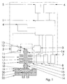
- Figure 1 shows a pump according to the first executed form of the present invention.
- a control system is shown according to the present invention.
- the system is driven by an electric power source that provides control voltage and supplies the system, via a voltage reader 5, with the energy needed to drive the system.
- the system consists of at least one microprocessor 1 that gathers all the data, stores the data, computes the data and sends the data onward. Data is gathered from at least one position sensor.
- the control system also contains at least one temperature sensor 4, at least one electric current meter 9 (ammeter) and at least one voltage measurer 8 (voltmeter). In alternative embodiments additional variations of the sensors may be utilized.
- the gathered data from the sensors are computed by the microprocessor and thereafter control signals are sent to an electric circuit 7 which in turn controls the electromagnets power supply.
- the electromagnets affect in turn a moving part whose position and movement is detected by at least one position sensor that preferably consists of at least one optical transmitter 2 that sends out light to at least one optical receiver 3.
- the control system also contains a network interface 6 that allows for several pumps to be controlled and/or for their cooperation with each other.
- the control system is designed to control several different types of electromagnetic driven pumps.
- the control system is used to control an electromagnetic driven membrane pump.
- the example should not be seen as a limitation on patent protection for a control system in accordance with the present invention because the control system is essentially designed to be used for all electromagnetic driven pumps.
- the membrane pump consists of a gable 22 that also contains circular hose connections.
- the gable 22 is joined together with a flange 20.
- a clack valve check valve, non-return valve, one-way valve or other device for preventing backflow
- a membrane 18 is clamped between the flange 20 and an additional flange 19. This provides for the formation of a pump chamber between the membrane and flange 20 with an intake and an outlet.
- An axle (the moving part) 12 is connected (fastened) to the membrane.
- the axle is suspended in slide bearings 14 and is designed to move in an axial direction.
- the axle has a wider part 17 that stretches out in radial direction.
- the wider part 17 can attract either of the two circular electromagnets 15 or 16 that surround the axle.
- the electromagnet attracts the axle's wider part 17 by the axle's wider part moving closer to the electromagnet because of the magnetic field formed by the electromagnet.
- an oscillating pumping movement can be established in an axial direction.
- one of the electromagnets can be replaced by a spring.
- the axial movement of the moving part that is created by the electromagnets' emitted magnetic field comes to different extent, at position 13 on the axle (the moving part) to obstruct the light sent from the optical transmitter 2 to the optical receiver 3.
- the moving part will in all positions to some extent always shade the light between the optical receiver and the optical transmitter.
- the obstructed light results in a shadow which size can be measured as analogous voltage at the receiver.
- the analogous voltage results in that the positioning optical sensor will have unlimited resolution.
- the optical receiver measures all light within all the wavelengths it is sensitive to, thus light can come from other directions and other sources and not just from the transmitter of the optical receiver.
- the optical transmitter is turned on and off with a very high frequency intensity so that the system can often control how much light that actually comes from the optical transmitter.
- an optical transmitter and an optical receiver are chosen that together have a light width (the width of the emitted or received cone of light) comprised of the distance between 10 to 11 that is larger than the pump's stroke length.
- a longer stroke length can however be measured by making a conic end on the axle (the moving part), but this however results in higher precision requirements on the axle's suspension so that no radial play occurs which the system might then misinterpret as an axial movement.
- the system has a temperature sensor 4 to compensate for possible changes (temperature drifting) in the electromagnet and the optical positioning sensor.
- the system also includes a function for automatic calibration of measurements to compensate for possible sources of error in the optical measurement of the moving part's position.
- the source of errors in the optical measurements could be caused by for example aging and wear during the operation of the pump.
- the automatic calibration is achieved by a mechanically well defined zero position or by means of the electromagnets mechanically setting the pump in its turning positions and thereafter optically measuring and updating the information on where the turning positions are expressed with the optical system's indication of position.
- the system is in this way protected from for example aging, operation or filth that with time could create differences in the analogous values measured on the optical receiver. In this way the whole chain from the operation of the optical transmitter to the reception of the optical receiver is calibrated.
- the control system for the pump receives its power via a voltmeter 5.
- the operational voltage's level also functions as control information for the pump, and in this way it becomes compatible with pumps operated by regular electrical direct-current (DC) motors, which are the most common existing type of pumps on the market today.
- DC direct-current
- the pump receives an external incoming voltage of six volts when connected to the voltmeter 5.
- the same voltage is parallelly connected to the microprocessor 1 at which it will turn on.
- the microprocessor begins by measuring the temperature of the system in order to use the temperature to compensate for possible measurement errors that originate from temperature. This takes place continuously in the software and is not mentioned further in this description.
- the microprocessor causes the optical transmitter to flash with a frequency of preferably 10 kHz.
- the microprocessor activates thereafter electromagnet 15 .
- the electromagnet pulls the pump's axle (moving part) in an axial direction toward the electromagnet 15 until the moving part reaches its turning position where it mechanically links with the electromagnet. Thereafter the microprocessor measures the voltage at the optical receiver 3. The voltage is both measured when the optical transmitter is turned on and off. The microprocessor calculates the differences in voltage and stores it in the memory as a defined turning position for the pump. The same procedure is executed for the other turning position by first deactivating electromagnet 15 and instead activating electromagnet 16. The microprocessor now knows both end positions of the pump and can thereby avoid striking against the turning positions. The microprocessor will now continuously measure the size of the shadow to continuously control exactly where between the turning positions the axle is found.
- the microprocessor measures the voltmeter 5 which shows six volts.
- the microprocessor has for example earlier been programmed that an incoming voltage of six volts gives a full stroke length and a stroke frequency of 6 Hz.
- the microprocessor has in this example been preprogrammed to recognize that the incoming voltage in volts indicates the stroke frequency.
- the microprocessor then causes the axle to oscillate by alternately activating the electromagnets back and forth. It uses the optical positioning sensor to change direction in time so that the pump avoids sinking its end points which would cause wear and tear.
- the adjustment of speed can for example be regulated with higher voltage to the electromagnet.
- the method used in this preferred solution is that by using an essentially higher frequency than the pump's speed, interrupt, turn off and on, the voltage coming in as voltage control, six volts in this case, with the aid of the electrical circuit 7 that controls the power supply to the electromagnet. It is therefore possible to minimize the number of components in the design and to avoid regulation of the voltage and therefore it is also possible to avoid energy losses in form of voltage drops in the control electronics 7.
- the operation voltage can also be kept constant and the pump can instead be controlled through the network interface 6 with the existing communication/network protocol that the pump has.
- the network interface is designed so that several control system can be controlled together and cooperate with each other and with other external sensors and systems. This allows for pumps to be controlled together to cooperate with each other, and also with other external sensors and systems. Through cooperation between several control system larger pumps can be operated by several or larger electromagnets. By using the network interface several pumps can work in parallel with the aim that they can together produce a larger flow. Even connecting in series provides a satisfactory effect for improving pressure performance. Parallel coupled pumps can through the control system's network interface work time delayed to compensate flow ripples through by letting the first pump pump out when the second pump pumps in. More than two pumps even out the ripples further. A further effect of network functionality is that the same bus can control several pumps with less electronics and connections.
- the network interface can also be wireless.
- the control system can also calculate from the pressure the pump generates. Somewhat simplified the method for measuring pressure is described according to the following.
- the size of the acceleration, in the direction that the electromagnet pulls the moving part, is a measure in the difference in force between the force that the electromagnet produces to pull the membrane and the counter-force that pulls the membrane in the opposite direction which stems from the positive pressure or negative pressure found in the pump chamber.
- control system can also be used to measure the pump's flow by way of flow performance/stroke at different pressures is measured and stored in the pump during production.
- the control system is used to control the pump in conjunction with dosage.
- the pump can dose because the flow performance/stroke at every specific pressure is known from calibration during production.
- the pumped volume the number of strokes* flow performance per stroke at the specific pressure.
- the control system can also be used to control the pump during the mixing of different mediums.
- the pump's flow measuring function together with the network function can be used to create a very simple and functional system that can with high precision mix different mediums.
- the control system can be used to gear up the pump.
- the pump can pump at full stroke length and later, when it is needed, reduce the stroke length and oscillate close to the operating electromagnet. This will achieve a significantly larger force to operate the membrane at which the emitted pressure can gear up.
Landscapes
- Engineering & Computer Science (AREA)
- General Engineering & Computer Science (AREA)
- Mechanical Engineering (AREA)
- Physics & Mathematics (AREA)
- Power Engineering (AREA)
- Electromagnetism (AREA)
- General Physics & Mathematics (AREA)
- Automation & Control Theory (AREA)
- Microelectronics & Electronic Packaging (AREA)
- Computer Hardware Design (AREA)
- Reciprocating Pumps (AREA)
- Control Of Positive-Displacement Pumps (AREA)
Description
- The present invention relates to an electromagnetic driven pump according to the preamble of
claim 1. - Electromagnetic pumps that apply pressure or negative pressure are found in a large variety of variations and sizes and are used in many different applications, everything from large industrial pumps to very small pumps for medical purposes. The diverse areas of use for electromagnetic pumps such as membrane pumps results in a plethora of requirements put upon the performance of such pumps. A significant problem for buyers of membrane pumps is that the supply of pumps from manufacturers is to a large degree standardized to just a few different models, largely because pump manufacturers seek economies of scale in their production. The limited diversity of pumps means that there exists a need for more efficient control systems. This would allow manufacturers to satisfy specific user needs in a much better way and thereby reduce costs as well as improve the performance of products that contain a pump. Today there is a lack of good quality, simple, standardized, low maintenance and inexpensive control systems for electromagnetic pumps.
- It is quite common that membrane pumps are driven with the aid of one or more electromagnets. An electromagnet produces a back and forth movement that for example causes the membrane to produce a pumping movement An advantage with electromagnetic driven membrane pumps is that they are more closely coupled to the membrane which renders it possible for example to vary the length of stroke, which can not be accomplished by membrane pumps powered by rotating motors with an eccentric. Furthermore, electromagnetic pumps are comprised of very few details which make them inexpensive to manufacture. Electromagnetic pumps are still less common despite this because of several problems that result in the fact that an electromagnet is not obviously better at powering a membrane pump compared with a rotating motor. A significant problem with electromagnetic driven pumps is that they are difficult to gear up for higher pressure without introducing lever that entail more details and additional friction. Yet another problem is that it is difficult to optimize electromagnetic pumps to turn precisely at their closing position without hitting the bottom of the pump. Hitting the bottom results in a shorter life span and turning to early results in poorer pressure performance. Electromagnetic pumps are therefore often pre-set to a certain pressure that can not be changed, which in turn is often a problem because this results in significant limitations. Still another problem with electromagnetic pumps is that they are more complicated to control than pumps with a rotating motor and they often can only be controlled by the amount of voltage.
- Additional problems that exist originate from the actual implementation and use of pumps. During the use of oscillating pumps such as electromagnetic pumps and pumps with rotating motors with eccentrics, oscillations are created in pressure and flow. These are in many cases unwanted and can for example disturb measuring sensors which measure the pumped medium. So called air capacitors, a large vessel or volume, are often used to even out the flow in order to minimize the disrupting oscillation. This is not however always a good solution because they take into use a lot of space and the pumped medium risks being mixed in these vessels before the medium finally reaches the gas sensor. This reduces for example the sensitivity and the response time of the measuring system. Another problem with the use of pumps is that flow is affected by how high the pressure is in the system. It is often desired that flow and pressure be constant. The performance of the pump depends a lot on if the surrounding pressure for some reason changes. This means that one must measure pressure or flow or both with good precision and in many applications this is necessary in order to control the pump. This increases the cost and complexity of the system. Yet another problem is when several pumps must be coordinated in order to attain a common result, such as the mixing of gases. This creates very complex systems with several flow meters, pressure meters and valves. It is also a problem to acquire a control system that is completely free from calibration and that is not affected by operation and aging.
- Because of the above mentioned problems systems and products that include pumps often give rise to very intricate designs comprised of many details making production very costly.
- In the document
US-A-4015912 , representing the closest prior art, optical sensors are used for securing that the pump does not reach its closing position by digitally reading a logical one or logical zero in order to stop or start the electromagnet, however this solution differs greatly from the solution described herein because their solution lacks information on what happens during all the remaining time that is comprised of the time the movable part is in all the other positions than just the two closing positions that are read. Nor does it have an incremental disbandment which is necessary for freely being able to vary the increments stroke for stroke during the time the pump pumps. It was suggested that a hole which can be moved with the aid of a thread be used for variable increments. Patent documentUS 6,616,413 describes a sensor-based control system that automatically adjusts the resonance frequency of an electromagnetic pump through induction. -
EP 0 211 474 A1 discloses a control circuit for controlling the supply of electric current to the solenoid windings of a solenoid operated diaphragm pump. This control circuit comprises a position sensor including a first optical receiver, which is arranged to receive light from a first optical transmitter, and a second optical receiver, which is arranged to receive light from a second optical transmitter. Switches included in the control circuit are switched off when the light signals between the first transmitter and the first receiver and between the second transmitter and the second receiver are interrupted by a moving part of the pump, which in its turn implies that the current supply to the solenoid windings is interrupted. This defines the terminal position of the forward stroke. During the return stroke, the light between the second transmitter and the second receiver and between the first transmitter and the first receiver is progressively uninterrupted by a progressive return of the moving part. The current supply to the solenoid windings is switched on when the moving part has reached such a position that light from the second transmitter is received by the second receiver and light from the first transmitter is received by the first receiver, which defines the terminal position of the return stroke. - Even if existing electromagnetic driven membrane pumps many times achieve there purposes, none of these combine the advantages from both membrane pumps driven by a rotating motor and membrane pumps driven by electromagnets without any of the disadvantages entailed by both types. The purpose of the present invention is therefore to bring about a membrane pump which encompasses the advantages from the respective types of membrane pumps essentially without any of there disadvantages. This system differs greatly from the system described herein, because their system lacks the precision and accuracy needed to solve all the problems described herein and essentially aims to optimizing efficiency.
- All the earlier mentioned problems result in that there exists a great potential for improving control systems for electromagnetic pumps. By utilizing the wide controllability and very direct coupling to the power source of electromagnetic pumps, it is possible to solve all the above problems in an eloquent manner and greatly improve and increase the areas of use for electromagnetic pumps, compared to pumps with a rotating motor as well as currently existing electromagnetic pumps which lack the control system described herein.
- The invention will be described in detail in the following text with reference to the enclosed schematic drawing which shows, in an exemplifying purpose, the current preferred embodiment of the invention.
-
Figure 1 shows a pump according to the first executed form of the present invention. - With reference to
figure 1 a control system is shown according to the present invention. The system is driven by an electric power source that provides control voltage and supplies the system, via avoltage reader 5, with the energy needed to drive the system. The system consists of at least onemicroprocessor 1 that gathers all the data, stores the data, computes the data and sends the data onward. Data is gathered from at least one position sensor. Preferably the control system also contains at least onetemperature sensor 4, at least one electric current meter 9 (ammeter) and at least one voltage measurer 8 (voltmeter). In alternative embodiments additional variations of the sensors may be utilized. The gathered data from the sensors are computed by the microprocessor and thereafter control signals are sent to anelectric circuit 7 which in turn controls the electromagnets power supply. The electromagnets affect in turn a moving part whose position and movement is detected by at least one position sensor that preferably consists of at least oneoptical transmitter 2 that sends out light to at least oneoptical receiver 3. The control system also contains anetwork interface 6 that allows for several pumps to be controlled and/or for their cooperation with each other. - The control system is designed to control several different types of electromagnetic driven pumps. In the exemplifying design of
figure 1 the control system is used to control an electromagnetic driven membrane pump. The example should not be seen as a limitation on patent protection for a control system in accordance with the present invention because the control system is essentially designed to be used for all electromagnetic driven pumps. The membrane pump consists of a gable 22 that also contains circular hose connections. The gable 22 is joined together with a flange 20. In the space between the gable 22 and the flange 20 exist a schematic drawing of a clack valve (check valve, non-return valve, one-way valve or other device for preventing backflow) 21 which can be comprised of for the purpose appropriate type of clack valve. Amembrane 18 is clamped between the flange 20 and an additional flange 19. This provides for the formation of a pump chamber between the membrane and flange 20 with an intake and an outlet. An axle (the moving part) 12 is connected (fastened) to the membrane. The axle is suspended inslide bearings 14 and is designed to move in an axial direction. The axle has awider part 17 that stretches out in radial direction. Thewider part 17 can attract either of the twocircular electromagnets wider part 17 by the axle's wider part moving closer to the electromagnet because of the magnetic field formed by the electromagnet. Through alternately activating theelectromagnets - The axial movement of the moving part that is created by the electromagnets' emitted magnetic field comes to different extent, at
position 13 on the axle (the moving part) to obstruct the light sent from theoptical transmitter 2 to theoptical receiver 3. The moving part will in all positions to some extent always shade the light between the optical receiver and the optical transmitter. The obstructed light results in a shadow which size can be measured as analogous voltage at the receiver. The analogous voltage results in that the positioning optical sensor will have unlimited resolution. The optical receiver measures all light within all the wavelengths it is sensitive to, thus light can come from other directions and other sources and not just from the transmitter of the optical receiver. To remove these sources of disturbance, the optical transmitter is turned on and off with a very high frequency intensity so that the system can often control how much light that actually comes from the optical transmitter. Suitably, an optical transmitter and an optical receiver are chosen that together have a light width (the width of the emitted or received cone of light) comprised of the distance between 10 to 11 that is larger than the pump's stroke length. A longer stroke length can however be measured by making a conic end on the axle (the moving part), but this however results in higher precision requirements on the axle's suspension so that no radial play occurs which the system might then misinterpret as an axial movement. The system has atemperature sensor 4 to compensate for possible changes (temperature drifting) in the electromagnet and the optical positioning sensor. - The system also includes a function for automatic calibration of measurements to compensate for possible sources of error in the optical measurement of the moving part's position. The source of errors in the optical measurements could be caused by for example aging and wear during the operation of the pump. The automatic calibration is achieved by a mechanically well defined zero position or by means of the electromagnets mechanically setting the pump in its turning positions and thereafter optically measuring and updating the information on where the turning positions are expressed with the optical system's indication of position. The system is in this way protected from for example aging, operation or filth that with time could create differences in the analogous values measured on the optical receiver. In this way the whole chain from the operation of the optical transmitter to the reception of the optical receiver is calibrated.
- The control system for the pump receives its power via a
voltmeter 5. By measuring the operational voltage the system is powered by, the operational voltage's level also functions as control information for the pump, and in this way it becomes compatible with pumps operated by regular electrical direct-current (DC) motors, which are the most common existing type of pumps on the market today. It is very advantageous to replace different types of pumps with the controlled pump according to present invention if the need arises to replace other pumps in existing equipment. A description on how this works will be described below. - The pump (the control system) receives an external incoming voltage of six volts when connected to the
voltmeter 5. The same voltage is parallelly connected to themicroprocessor 1 at which it will turn on. The microprocessor begins by measuring the temperature of the system in order to use the temperature to compensate for possible measurement errors that originate from temperature. This takes place continuously in the software and is not mentioned further in this description. The microprocessor causes the optical transmitter to flash with a frequency of preferably 10 kHz. The microprocessor activates thereafterelectromagnet 15 . - The electromagnet pulls the pump's axle (moving part) in an axial direction toward the
electromagnet 15 until the moving part reaches its turning position where it mechanically links with the electromagnet. Thereafter the microprocessor measures the voltage at theoptical receiver 3. The voltage is both measured when the optical transmitter is turned on and off. The microprocessor calculates the differences in voltage and stores it in the memory as a defined turning position for the pump. The same procedure is executed for the other turning position by first deactivatingelectromagnet 15 and instead activatingelectromagnet 16. The microprocessor now knows both end positions of the pump and can thereby avoid striking against the turning positions. The microprocessor will now continuously measure the size of the shadow to continuously control exactly where between the turning positions the axle is found. With help from a so called linearity table the voltage differences can be translated to a specific position despite of that the size of the shadow is not totally linear in relation to the voltage differences. Then the microprocessor measures thevoltmeter 5 which shows six volts. The microprocessor has for example earlier been programmed that an incoming voltage of six volts gives a full stroke length and a stroke frequency of 6 Hz. The microprocessor has in this example been preprogrammed to recognize that the incoming voltage in volts indicates the stroke frequency. The microprocessor then causes the axle to oscillate by alternately activating the electromagnets back and forth. It uses the optical positioning sensor to change direction in time so that the pump avoids sinking its end points which would cause wear and tear. It will adjust the speed of the pump so that a frequency of 6 Hz is achieved. The adjustment of speed can for example be regulated with higher voltage to the electromagnet. The method used in this preferred solution, is that by using an essentially higher frequency than the pump's speed, interrupt, turn off and on, the voltage coming in as voltage control, six volts in this case, with the aid of theelectrical circuit 7 that controls the power supply to the electromagnet. It is therefore possible to minimize the number of components in the design and to avoid regulation of the voltage and therefore it is also possible to avoid energy losses in form of voltage drops in thecontrol electronics 7. - If the operation voltage for the control system in this case is raised to seven volts the system's control program will maintain the full stroke length but raise the stroke frequency to seven Hz accordingly. In this way it is possible to imitate a direct-current (DC) motor and thus have the possibility to replace existing direct-current (DC) driven pumps on the market. Changes in operation voltage can of course control other things than frequency. Frequency can be held constant and the stroke length can be controlled by the operation voltage. Furthermore the operation voltage can control the actual flow or pressure which will be described later herein. A linear pump function can then be achieved.
- The operation voltage can also be kept constant and the pump can instead be controlled through the
network interface 6 with the existing communication/network protocol that the pump has. The network interface is designed so that several control system can be controlled together and cooperate with each other and with other external sensors and systems. This allows for pumps to be controlled together to cooperate with each other, and also with other external sensors and systems. Through cooperation between several control system larger pumps can be operated by several or larger electromagnets. By using the network interface several pumps can work in parallel with the aim that they can together produce a larger flow. Even connecting in series provides a satisfactory effect for improving pressure performance. Parallel coupled pumps can through the control system's network interface work time delayed to compensate flow ripples through by letting the first pump pump out when the second pump pumps in. More than two pumps even out the ripples further. A further effect of network functionality is that the same bus can control several pumps with less electronics and connections. The network interface can also be wireless. - The control system can also calculate from the pressure the pump generates. Somewhat simplified the method for measuring pressure is described according to the following. The size of the acceleration, in the direction that the electromagnet pulls the moving part, is a measure in the difference in force between the force that the electromagnet produces to pull the membrane and the counter-force that pulls the membrane in the opposite direction which stems from the positive pressure or negative pressure found in the pump chamber.
- With the aid of the position sensor it is known where the moving part is, how fast it is moving and its acceleration at any given moment. The force that the electromagnet produces at every distance to the axel is already known by way of measuring (calibration). When the acceleration is measured and compared with the known force the formula A = F 1- F2 can be used to calculate the unknown force produced by the pressure in the pump. Later, when the force produced from the pressure is known it is possible to calculate the pressure's size with the formula P = F/A.
- Of course there are other factors which influence as for example friction in bearings, elasticity of the membrane, further elasticity, air resistance and temperature. However, the importance of these parameters will depend on how every pump is constructed, and this is why they are left out of this simplified description.
- Apart from earlier mentioned areas of use, the control system can also be used to measure the pump's flow by way of flow performance/stroke at different pressures is measured and stored in the pump during production. Thus the flow can be calculated with the aid of the formula, Flow = Stroke frequency * Flow performance at the specific pressure.
- The control system is used to control the pump in conjunction with dosage. The pump can dose because the flow performance/stroke at every specific pressure is known from calibration during production. The pumped volume = the number of strokes* flow performance per stroke at the specific pressure.
- The control system can also be used to control the pump during the mixing of different mediums. With the aid of the control system the pump's flow measuring function together with the network function can be used to create a very simple and functional system that can with high precision mix different mediums.
- The control system can be used to gear up the pump. The pump can pump at full stroke length and later, when it is needed, reduce the stroke length and oscillate close to the operating electromagnet. This will achieve a significantly larger force to operate the membrane at which the emitted pressure can gear up.
- Even if the preferred embodiment of the control system and the method for controlling the control system have been described in detail herein, variations and smaller changes within the scope of the invention may become known for those skilled in the art and all such cases will be considered to fall within the scope of the following claims.
Claims (20)
- An electromagnetic driven pump, as for example an electromagnetic driven membrane pump, which comprises a control system including at least one microprocessor (1) and at least one sensor, where the microprocessor controls the energy feed to at least one electromagnet (15, 16), at which changes in the emitted magnetic field causes at least one moving part (12) to perform an oscillating movement to achieve a pumping effect and at which at least one position sensor is placed to sense the position of the moving part (12) in the electromagnetic driven pump, characterized in that the position sensor includes at least one optical transmitter (2) and at least one optical receiver (3), that the moving part (12) of the pump shades the light between the transmitter and the receiver to an extent that the size of the shaded area depends on the moving part's position, and that the microprocessor (1) is set to continuously calculate, in relation to the size of the shaded area, the moving part's position from the size of the shadow which corresponds to the voltage at the optical receiver (3).
- A pump according to claim 1, characterized in that the moving part in all positions shades the light between the transmitter and receiver.
- A pump according to claim 1, characterized in that the microprocessor (1), for automatic calibration of the position sensor function, is designed to record the voltage from the optical receiver (3) with the moving part pulled by the electromagnet (15, 16) to at least one known position.
- A pump according to claims 1 or 2, characterized in that the optical transmitter (2) is designed to flash with at least 20 times higher frequency than the stroke frequency of the pump.
- A pump according to any of the previous claims, characterized in that sensors are set up to measure the pump's emitted pressure by measuring the moving part's (12) acceleration during the pump's stroke.
- A pump according to any of previous claims, characterized in that the microprocessor (1) is connected to at least one sensor (9) which is designed to record the current, that passes through the electromagnets (15, 16).
- A pump according to any of previous claims, characterized in that the microprocessor (1) is connected to at least one temperature sensor (4) in order to use measured temperature data for temperature compensation of the control system.
- A pump according to any of previous claims, characterized in that sensors are set up to measure flow with the aid of the known flow performance for each pump stroke at different pressures.
- A pump according to any of previous claims, characterized in that the microprocessor (1) is designed to be controlled by the incoming voltage level that is measured by a voltmeter (5).
- A pump according to any of previous claims, characterized in the control system being comprised of a function where the pump is driven with a constant frequency and the flow is varied with the moving part's (12) stroke length.
- A pump according to any of previous claims, characterized in that the control system is synchronized in time with external systems or sensors to control the pump to perform the pumping movement when it is most advantageous for the surrounding systems or sensors.
- A pump according to any of previous claims, characterized in that the control system comprises a function for control of the pump to produce single strokes of variable length.
- A pump according to any of the previous claims, characterized in that the microprocessor (1) is comprised of a network function (6) that renders it possible to join together several control systems.
- A pump according to claim 12, characterized in that the control system is designed to use flow measurement and the network function to control the pump during the mixing of gases.
- A pump according to claim 12, characterized in that the control system is designed to utilize the network function to cooperate with several control systems to drive larger pumps by use of several or larger electromagnets.
- A pump according to claim 12, characterized in that the control system is designed to use its network function to time delay the pump stroke between several connected pumps to even out flow ripples.
- A pump according to claim 12, characterized in that the control system is designed to use its network function to control several parallel coupled pumps to increase flow performance.
- A pump according to claim 12, characterized in that the control system is designed to use its network function to control the serial coupling of pumps to increase pressure performance.
- A pump according to any of previous claims, characterized in that the control system is designed to use flow measurement to control the pump with a linear function for flow proportional against the incoming voltage.
- A pump according to any of claims 1 - 17, characterized in that the control system is designed to use pressure measurement to control the pump with a linear function for pressure proportional against the incoming voltage.
Applications Claiming Priority (2)
| Application Number | Priority Date | Filing Date | Title |
|---|---|---|---|
| SE0502508A SE529328C2 (en) | 2005-11-15 | 2005-11-15 | Control system and method for controlling electromagnetically driven pumps |
| PCT/SE2006/001277 WO2007058579A1 (en) | 2005-11-15 | 2006-11-12 | Control system for electromagnetic pumps |
Publications (3)
| Publication Number | Publication Date |
|---|---|
| EP1948931A1 EP1948931A1 (en) | 2008-07-30 |
| EP1948931A4 EP1948931A4 (en) | 2011-07-20 |
| EP1948931B1 true EP1948931B1 (en) | 2012-10-17 |
Family
ID=38048892
Family Applications (1)
| Application Number | Title | Priority Date | Filing Date |
|---|---|---|---|
| EP06813000A Active EP1948931B1 (en) | 2005-11-15 | 2006-11-12 | Electromagnetic pump with control system |
Country Status (9)
| Country | Link |
|---|---|
| US (2) | US8807965B2 (en) |
| EP (1) | EP1948931B1 (en) |
| JP (1) | JP2009521635A (en) |
| KR (1) | KR101263854B1 (en) |
| CN (1) | CN101310109B (en) |
| DK (1) | DK1948931T3 (en) |
| ES (1) | ES2397855T3 (en) |
| SE (1) | SE529328C2 (en) |
| WO (1) | WO2007058579A1 (en) |
Families Citing this family (23)
| Publication number | Priority date | Publication date | Assignee | Title |
|---|---|---|---|---|
| SE529328C2 (en) * | 2005-11-15 | 2007-07-10 | Johan Stenberg | Control system and method for controlling electromagnetically driven pumps |
| SE532405C2 (en) * | 2008-05-02 | 2010-01-12 | Johan Stenberg | Pump system and method for determining a pressure value |
| WO2010069321A2 (en) | 2008-12-19 | 2010-06-24 | Stobbe Tech A/S | Electronically controlled diaphragm pump |
| EP2396547A1 (en) * | 2009-02-12 | 2011-12-21 | The Board Of Trustees Of The University Of Illinois | Magnetically driven micropump |
| CH702437A1 (en) * | 2009-12-23 | 2011-06-30 | Jean-Denis Rochat | Volumetric pump diaphragm alternative medical use. |
| DE102010003218A1 (en) * | 2010-03-24 | 2011-09-29 | Prominent Dosiertechnik Gmbh | Method for controlling and / or regulating a metering pump |
| US10589239B2 (en) * | 2010-07-07 | 2020-03-17 | Ge Healthcare Bio-Sciences Ab | Fluid mixing in a disposable fluid processing system |
| JP5624825B2 (en) * | 2010-07-29 | 2014-11-12 | 株式会社日立ハイテクノロジーズ | Liquid chromatograph pump and liquid chromatograph |
| RU2584806C2 (en) * | 2010-08-13 | 2016-05-20 | Конинклейке Филипс Электроникс Н.В. | System and method for delivery of pressurised breathing gas flow in airway of subject using stochastic fluctuations |
| US20150086386A1 (en) * | 2012-04-23 | 2015-03-26 | Siemens Healthcare Diagnostics Inc. | Multi-chamber pump apparatus, systems, and methods |
| CN202759406U (en) * | 2012-06-28 | 2013-02-27 | 控制技术有限公司 | Optimal switching system for frequency converter-driven multi-motor control system |
| US20140271275A1 (en) * | 2013-03-14 | 2014-09-18 | Tuthill Corporation | Variable Stroke Length Electrically Operated Diaphragm Pump |
| DE102013109412A1 (en) * | 2013-08-29 | 2015-03-05 | Prominent Gmbh | Method for improving metering profiles of positive displacement pumps |
| DE102013113351A1 (en) | 2013-12-03 | 2015-06-03 | Pfeiffer Vacuum Gmbh | Method for calibrating a membrane vacuum pump and membrane vacuum pump |
| CN104847960B (en) * | 2015-05-29 | 2017-06-13 | 浙江新控泵业有限公司 | Water pump with photoelectricity fluid sensor |
| DE102015210208A1 (en) | 2015-06-02 | 2016-12-08 | Gemü Gebr. Müller Apparatebau Gmbh & Co. Kommanditgesellschaft | Method for determining a state variable of a valve diaphragm of an electronically controlled and motor-driven diaphragm valve, and diaphragm valve system |
| US9360871B1 (en) * | 2015-10-07 | 2016-06-07 | Charles Jorgensen | Integrated fluid flow management apparatus |
| JP6892982B2 (en) | 2017-02-03 | 2021-06-23 | 応研精工株式会社 | Diaphragm pump |
| CN107366613A (en) * | 2017-08-17 | 2017-11-21 | 深圳华星恒泰泵阀有限公司 | A kind of pump of built-in photosensitive metering device |
| CN107339205A (en) * | 2017-08-17 | 2017-11-10 | 深圳华星恒泰泵阀有限公司 | A kind of pump of built-in Vibration induction metering device |
| CN113123946A (en) * | 2021-04-26 | 2021-07-16 | 长春工业大学 | A have valve resonance piezoelectric pump for agricultural sprinkling irrigation |
| DE102022126376A1 (en) * | 2022-10-11 | 2024-04-11 | Prominent Gmbh | Method for sensorless detection of the stroke execution in a magnetic pump |
| DE102024101605A1 (en) * | 2024-01-19 | 2025-07-24 | Knf Flodos Ag | Diaphragm pump and arrangement and method for conveying a fluid and associated control unit |
Family Cites Families (40)
| Publication number | Priority date | Publication date | Assignee | Title |
|---|---|---|---|---|
| US3411704A (en) * | 1966-09-26 | 1968-11-19 | Johnson Service Co | Pneumatic controller |
| US3610782A (en) * | 1969-10-06 | 1971-10-05 | Precision Control Products Cor | Controlled pump |
| US3864695A (en) * | 1972-09-25 | 1975-02-04 | Asahi Optical Co Ltd | Pen having vertical movement control |
| DE2414165A1 (en) * | 1974-03-23 | 1975-10-09 | Eberspaecher J | ELECTROMAGNETIC TRANSFER DEVICE FOR LIQUIDS |
| DE3202069C2 (en) * | 1982-01-23 | 1984-05-03 | Chemie Und Filter Gmbh, Verfahrenstechnik Kg, 6900 Heidelberg | "Diaphragm pump, especially metering pump" |
| US5047154A (en) * | 1983-03-10 | 1991-09-10 | C.P.C. Engineering Company | Method and apparatus for enhancing the flux rate of cross-flow filtration systems |
| DE3410529A1 (en) * | 1984-03-22 | 1985-10-03 | Fa. J. Eberspächer, 7300 Esslingen | CONTROL DEVICE FOR A DOSING PUMP |
| EP0211474A1 (en) * | 1985-05-07 | 1987-02-25 | Electronic Components Company Ltd | Control circuit for the reciprocating movement of a solenoid armature |
| FR2588319B1 (en) * | 1985-10-04 | 1987-12-04 | Milton Roy Dosapro | PROCESS FOR PRECISELY ESTABLISHING THE FLOW RATE OF A METERING PUMP AND METERING PUMP USING THE SAME |
| JP2529552B2 (en) * | 1986-07-18 | 1996-08-28 | 株式会社 長野計器製作所 | Control device for electromagnetic reciprocating pump |
| US4874299A (en) * | 1987-04-08 | 1989-10-17 | Life Loc, Inc. | High precision pump |
| US4749553A (en) * | 1987-04-08 | 1988-06-07 | Life Loc, Inc. | Breath alcohol detector with improved compensation for environmental variables |
| US4966533A (en) * | 1987-07-14 | 1990-10-30 | Kabushiki Kaisha Nagano Keiki Seisakusho | Vacuum pump with rotational sliding piston support |
| US5056036A (en) * | 1989-10-20 | 1991-10-08 | Pulsafeeder, Inc. | Computer controlled metering pump |
| CN2084524U (en) * | 1990-10-27 | 1991-09-11 | 朴凤浩 | Moving-coil electromagnetic diaphragm pump |
| US5017854A (en) * | 1990-10-29 | 1991-05-21 | Hughes Aircraft Company | Variable duty cycle pulse width modulated motor control system |
| US5259731A (en) * | 1991-04-23 | 1993-11-09 | Dhindsa Jasbir S | Multiple reciprocating pump system |
| CN2108895U (en) * | 1991-11-18 | 1992-07-01 | 北京信安高技术公司 | Linearity light bit shift sensor |
| US5257914A (en) * | 1992-06-24 | 1993-11-02 | Warren Rupp, Inc. | Electronic control interface for fluid powered diaphragm pump |
| US5641270A (en) * | 1995-07-31 | 1997-06-24 | Waters Investments Limited | Durable high-precision magnetostrictive pump |
| US5809157A (en) * | 1996-04-09 | 1998-09-15 | Victor Lavrov | Electromagnetic linear drive |
| US6616413B2 (en) | 1998-03-20 | 2003-09-09 | James C. Humpheries | Automatic optimizing pump and sensor system |
| DE59910632D1 (en) * | 1998-07-17 | 2004-11-04 | Bayerische Motoren Werke Ag | Method for controlling the movement of an armature of an electromagnetic actuator |
| US6174136B1 (en) * | 1998-10-13 | 2001-01-16 | Liquid Metronics Incorporated | Pump control and method of operating same |
| US6280147B1 (en) * | 1998-10-13 | 2001-08-28 | Liquid Metronics Incorporated | Apparatus for adjusting the stroke length of a pump element |
| CH693468A5 (en) * | 1998-12-16 | 2003-08-15 | Hera Rotterdam Bv | Method and apparatus for detecting or determining the position of edges. |
| US6535308B1 (en) * | 1999-02-12 | 2003-03-18 | Marconi Communications, Inc. | Method and apparatus for converting electrical signals and optical signals for bidirectional communication over a single optical fiber |
| DE19920181A1 (en) * | 1999-05-03 | 2000-11-09 | Fev Motorentech Gmbh | Method for controlling the armature impact speed on an electromagnetic actuator by means of a map-based regulation of the current supply |
| US6468042B2 (en) * | 1999-07-12 | 2002-10-22 | Danfoss Drives A/S | Method for regulating a delivery variable of a pump |
| JP3617413B2 (en) * | 2000-06-02 | 2005-02-02 | 日産自動車株式会社 | Control device for electromagnetically driven valve |
| JP4281257B2 (en) * | 2000-06-29 | 2009-06-17 | トヨタ自動車株式会社 | Engine valve drive control device |
| CN2481872Y (en) * | 2001-01-03 | 2002-03-13 | 汪良桥 | Electromagnetic diaphragm gasoline pump |
| JP4218261B2 (en) * | 2002-06-11 | 2009-02-04 | ダイキン工業株式会社 | Pumping unit |
| DE102005039237A1 (en) * | 2005-08-19 | 2007-02-22 | Prominent Dosiertechnik Gmbh | motor-driven metering |
| DE102005039772A1 (en) * | 2005-08-22 | 2007-03-08 | Prominent Dosiertechnik Gmbh | solenoid |
| SE529284C2 (en) * | 2005-11-14 | 2007-06-19 | Johan Stenberg | diaphragm Pump |
| SE529328C2 (en) * | 2005-11-15 | 2007-07-10 | Johan Stenberg | Control system and method for controlling electromagnetically driven pumps |
| SE532405C2 (en) * | 2008-05-02 | 2010-01-12 | Johan Stenberg | Pump system and method for determining a pressure value |
| US8708665B2 (en) * | 2008-05-02 | 2014-04-29 | Xavitech Ab | Membrane pump operating in both audible and inaudible frequency regions |
| WO2010128914A1 (en) * | 2009-05-08 | 2010-11-11 | Xavitech Ab | A membrane pump |
-
2005
- 2005-11-15 SE SE0502508A patent/SE529328C2/en not_active IP Right Cessation
-
2006
- 2006-11-12 US US12/085,089 patent/US8807965B2/en active Active
- 2006-11-12 KR KR1020087014554A patent/KR101263854B1/en not_active Expired - Fee Related
- 2006-11-12 ES ES06813000T patent/ES2397855T3/en active Active
- 2006-11-12 EP EP06813000A patent/EP1948931B1/en active Active
- 2006-11-12 CN CN2006800425804A patent/CN101310109B/en not_active Expired - Fee Related
- 2006-11-12 WO PCT/SE2006/001277 patent/WO2007058579A1/en not_active Ceased
- 2006-11-12 DK DK06813000.4T patent/DK1948931T3/en active
- 2006-11-12 JP JP2008539982A patent/JP2009521635A/en active Pending
-
2014
- 2014-07-01 US US14/321,216 patent/US9547293B2/en active Active
Also Published As
| Publication number | Publication date |
|---|---|
| CN101310109B (en) | 2011-07-06 |
| JP2009521635A (en) | 2009-06-04 |
| SE529328C2 (en) | 2007-07-10 |
| US8807965B2 (en) | 2014-08-19 |
| EP1948931A4 (en) | 2011-07-20 |
| SE0502508L (en) | 2007-05-16 |
| EP1948931A1 (en) | 2008-07-30 |
| ES2397855T3 (en) | 2013-03-11 |
| US9547293B2 (en) | 2017-01-17 |
| KR20080079260A (en) | 2008-08-29 |
| US20090047137A1 (en) | 2009-02-19 |
| WO2007058579A1 (en) | 2007-05-24 |
| CN101310109A (en) | 2008-11-19 |
| KR101263854B1 (en) | 2013-05-13 |
| DK1948931T3 (en) | 2013-02-04 |
| US20140316590A1 (en) | 2014-10-23 |
Similar Documents
| Publication | Publication Date | Title |
|---|---|---|
| US9547293B2 (en) | Control system for electromagnetic pumps | |
| KR101864806B1 (en) | Membrane vacuum pump | |
| US9316218B2 (en) | Method and apparatus for increasing compressed air efficiency in a pump | |
| US5012722A (en) | Floating coil servo valve | |
| US9158308B2 (en) | Apparatus using electronically-controlled valves | |
| CN107084107B (en) | Electronic sensing control swash plate type variable plunger pump and hydraulic plunger pump | |
| US20040234377A1 (en) | Dosing pump | |
| JP5185256B2 (en) | Method and apparatus for controlling fluid flow | |
| JP2013522537A (en) | Method for controlling and / or adjusting metering pump | |
| JP2018091862A (en) | System and method for regulating and measuring flow | |
| EP3513073A2 (en) | Displacement pump and control system | |
| CN206830394U (en) | An electronic sensor control swash plate type variable displacement plunger pump, hydraulic plunger pump | |
| EP0814270B1 (en) | Electric-to-pressure converters | |
| CN120140169A (en) | A digital hydraulic pump controlled by a high-speed switch valve bridge | |
| US10927834B2 (en) | Method of operating a lubricating device, lubricating device and compressor with such a lubricating device | |
| JP2007303416A (en) | Variable capacity compressor | |
| CN210003479U (en) | feedback control electro-hydraulic proportional variable axial plunger pump | |
| CN210509500U (en) | Constant power variable pump | |
| JP3618456B2 (en) | Liquid material supply device flow control mechanism | |
| Dahms et al. | B7. 3-Instrinsic Flow Control of a Piezo Membrane Pump | |
| CN121976945A (en) | A dynamic pump speed calibration device and method based on weighing feedback | |
| JPH1077962A (en) | Electromagnetic pump |
Legal Events
| Date | Code | Title | Description |
|---|---|---|---|
| PUAI | Public reference made under article 153(3) epc to a published international application that has entered the european phase |
Free format text: ORIGINAL CODE: 0009012 |
|
| 17P | Request for examination filed |
Effective date: 20080331 |
|
| AK | Designated contracting states |
Kind code of ref document: A1 Designated state(s): AT BE BG CH CY CZ DE DK EE ES FI FR GB GR HU IE IS IT LI LT LU LV MC NL PL PT RO SE SI SK TR |
|
| RAP1 | Party data changed (applicant data changed or rights of an application transferred) |
Owner name: XAVITECH AB |
|
| RIN1 | Information on inventor provided before grant (corrected) |
Inventor name: STENBERG, JOHAN |
|
| A4 | Supplementary search report drawn up and despatched |
Effective date: 20110617 |
|
| RIC1 | Information provided on ipc code assigned before grant |
Ipc: F04B 43/04 20060101AFI20070720BHEP Ipc: F04B 49/06 20060101ALI20110610BHEP Ipc: H02K 33/12 20060101ALI20110610BHEP Ipc: H01H 51/12 20060101ALI20110610BHEP Ipc: F04B 43/00 20060101ALI20110610BHEP |
|
| RIC1 | Information provided on ipc code assigned before grant |
Ipc: H02K 33/12 20060101ALI20120314BHEP Ipc: F04B 43/04 20060101AFI20120314BHEP Ipc: F04B 43/00 20060101ALI20120314BHEP Ipc: F04B 49/06 20060101ALI20120314BHEP Ipc: H01H 51/12 20060101ALI20120314BHEP |
|
| RTI1 | Title (correction) |
Free format text: ELECTROMAGNETIC PUMP WITH CONTROL SYSTEM |
|
| GRAP | Despatch of communication of intention to grant a patent |
Free format text: ORIGINAL CODE: EPIDOSNIGR1 |
|
| DAX | Request for extension of the european patent (deleted) | ||
| GRAS | Grant fee paid |
Free format text: ORIGINAL CODE: EPIDOSNIGR3 |
|
| GRAA | (expected) grant |
Free format text: ORIGINAL CODE: 0009210 |
|
| AK | Designated contracting states |
Kind code of ref document: B1 Designated state(s): AT BE BG CH CY CZ DE DK EE ES FI FR GB GR HU IE IS IT LI LT LU LV MC NL PL PT RO SE SI SK TR |
|
| REG | Reference to a national code |
Ref country code: GB Ref legal event code: FG4D |
|
| REG | Reference to a national code |
Ref country code: CH Ref legal event code: EP |
|
| REG | Reference to a national code |
Ref country code: IE Ref legal event code: FG4D |
|
| REG | Reference to a national code |
Ref country code: AT Ref legal event code: REF Ref document number: 580031 Country of ref document: AT Kind code of ref document: T Effective date: 20121115 |
|
| REG | Reference to a national code |
Ref country code: DE Ref legal event code: R096 Ref document number: 602006032546 Country of ref document: DE Effective date: 20121220 |
|
| REG | Reference to a national code |
Ref country code: CH Ref legal event code: NV Representative=s name: P&TS SA, CH |
|
| REG | Reference to a national code |
Ref country code: DK Ref legal event code: T3 |
|
| REG | Reference to a national code |
Ref country code: NL Ref legal event code: T3 |
|
| RAP2 | Party data changed (patent owner data changed or rights of a patent transferred) |
Owner name: XAVITECH AB |
|
| REG | Reference to a national code |
Ref country code: ES Ref legal event code: FG2A Ref document number: 2397855 Country of ref document: ES Kind code of ref document: T3 Effective date: 20130311 |
|
| REG | Reference to a national code |
Ref country code: AT Ref legal event code: MK05 Ref document number: 580031 Country of ref document: AT Kind code of ref document: T Effective date: 20121017 |
|
| REG | Reference to a national code |
Ref country code: LT Ref legal event code: MG4D |
|
| PG25 | Lapsed in a contracting state [announced via postgrant information from national office to epo] |
Ref country code: SE Free format text: LAPSE BECAUSE OF FAILURE TO SUBMIT A TRANSLATION OF THE DESCRIPTION OR TO PAY THE FEE WITHIN THE PRESCRIBED TIME-LIMIT Effective date: 20121017 Ref country code: IS Free format text: LAPSE BECAUSE OF FAILURE TO SUBMIT A TRANSLATION OF THE DESCRIPTION OR TO PAY THE FEE WITHIN THE PRESCRIBED TIME-LIMIT Effective date: 20130217 Ref country code: FI Free format text: LAPSE BECAUSE OF FAILURE TO SUBMIT A TRANSLATION OF THE DESCRIPTION OR TO PAY THE FEE WITHIN THE PRESCRIBED TIME-LIMIT Effective date: 20121017 Ref country code: LT Free format text: LAPSE BECAUSE OF FAILURE TO SUBMIT A TRANSLATION OF THE DESCRIPTION OR TO PAY THE FEE WITHIN THE PRESCRIBED TIME-LIMIT Effective date: 20121017 |
|
| PG25 | Lapsed in a contracting state [announced via postgrant information from national office to epo] |
Ref country code: PT Free format text: LAPSE BECAUSE OF FAILURE TO SUBMIT A TRANSLATION OF THE DESCRIPTION OR TO PAY THE FEE WITHIN THE PRESCRIBED TIME-LIMIT Effective date: 20130218 Ref country code: GR Free format text: LAPSE BECAUSE OF FAILURE TO SUBMIT A TRANSLATION OF THE DESCRIPTION OR TO PAY THE FEE WITHIN THE PRESCRIBED TIME-LIMIT Effective date: 20130118 Ref country code: SI Free format text: LAPSE BECAUSE OF FAILURE TO SUBMIT A TRANSLATION OF THE DESCRIPTION OR TO PAY THE FEE WITHIN THE PRESCRIBED TIME-LIMIT Effective date: 20121017 Ref country code: BE Free format text: LAPSE BECAUSE OF FAILURE TO SUBMIT A TRANSLATION OF THE DESCRIPTION OR TO PAY THE FEE WITHIN THE PRESCRIBED TIME-LIMIT Effective date: 20121017 Ref country code: LV Free format text: LAPSE BECAUSE OF FAILURE TO SUBMIT A TRANSLATION OF THE DESCRIPTION OR TO PAY THE FEE WITHIN THE PRESCRIBED TIME-LIMIT Effective date: 20121017 Ref country code: PL Free format text: LAPSE BECAUSE OF FAILURE TO SUBMIT A TRANSLATION OF THE DESCRIPTION OR TO PAY THE FEE WITHIN THE PRESCRIBED TIME-LIMIT Effective date: 20121017 Ref country code: CY Free format text: LAPSE BECAUSE OF FAILURE TO SUBMIT A TRANSLATION OF THE DESCRIPTION OR TO PAY THE FEE WITHIN THE PRESCRIBED TIME-LIMIT Effective date: 20121017 |
|
| PG25 | Lapsed in a contracting state [announced via postgrant information from national office to epo] |
Ref country code: AT Free format text: LAPSE BECAUSE OF FAILURE TO SUBMIT A TRANSLATION OF THE DESCRIPTION OR TO PAY THE FEE WITHIN THE PRESCRIBED TIME-LIMIT Effective date: 20121017 |
|
| PG25 | Lapsed in a contracting state [announced via postgrant information from national office to epo] |
Ref country code: CZ Free format text: LAPSE BECAUSE OF FAILURE TO SUBMIT A TRANSLATION OF THE DESCRIPTION OR TO PAY THE FEE WITHIN THE PRESCRIBED TIME-LIMIT Effective date: 20121017 Ref country code: BG Free format text: LAPSE BECAUSE OF FAILURE TO SUBMIT A TRANSLATION OF THE DESCRIPTION OR TO PAY THE FEE WITHIN THE PRESCRIBED TIME-LIMIT Effective date: 20130117 Ref country code: SK Free format text: LAPSE BECAUSE OF FAILURE TO SUBMIT A TRANSLATION OF THE DESCRIPTION OR TO PAY THE FEE WITHIN THE PRESCRIBED TIME-LIMIT Effective date: 20121017 Ref country code: EE Free format text: LAPSE BECAUSE OF FAILURE TO SUBMIT A TRANSLATION OF THE DESCRIPTION OR TO PAY THE FEE WITHIN THE PRESCRIBED TIME-LIMIT Effective date: 20121017 |
|
| REG | Reference to a national code |
Ref country code: IE Ref legal event code: MM4A |
|
| PLBE | No opposition filed within time limit |
Free format text: ORIGINAL CODE: 0009261 |
|
| STAA | Information on the status of an ep patent application or granted ep patent |
Free format text: STATUS: NO OPPOSITION FILED WITHIN TIME LIMIT |
|
| PG25 | Lapsed in a contracting state [announced via postgrant information from national office to epo] |
Ref country code: RO Free format text: LAPSE BECAUSE OF FAILURE TO SUBMIT A TRANSLATION OF THE DESCRIPTION OR TO PAY THE FEE WITHIN THE PRESCRIBED TIME-LIMIT Effective date: 20121017 |
|
| 26N | No opposition filed |
Effective date: 20130718 |
|
| PG25 | Lapsed in a contracting state [announced via postgrant information from national office to epo] |
Ref country code: IE Free format text: LAPSE BECAUSE OF NON-PAYMENT OF DUE FEES Effective date: 20121112 |
|
| REG | Reference to a national code |
Ref country code: DE Ref legal event code: R097 Ref document number: 602006032546 Country of ref document: DE Effective date: 20130718 |
|
| PG25 | Lapsed in a contracting state [announced via postgrant information from national office to epo] |
Ref country code: MC Free format text: LAPSE BECAUSE OF NON-PAYMENT OF DUE FEES Effective date: 20121130 Ref country code: TR Free format text: LAPSE BECAUSE OF FAILURE TO SUBMIT A TRANSLATION OF THE DESCRIPTION OR TO PAY THE FEE WITHIN THE PRESCRIBED TIME-LIMIT Effective date: 20121017 |
|
| PG25 | Lapsed in a contracting state [announced via postgrant information from national office to epo] |
Ref country code: LU Free format text: LAPSE BECAUSE OF NON-PAYMENT OF DUE FEES Effective date: 20121112 |
|
| PG25 | Lapsed in a contracting state [announced via postgrant information from national office to epo] |
Ref country code: HU Free format text: LAPSE BECAUSE OF FAILURE TO SUBMIT A TRANSLATION OF THE DESCRIPTION OR TO PAY THE FEE WITHIN THE PRESCRIBED TIME-LIMIT Effective date: 20061112 |
|
| REG | Reference to a national code |
Ref country code: FR Ref legal event code: PLFP Year of fee payment: 10 |
|
| REG | Reference to a national code |
Ref country code: FR Ref legal event code: PLFP Year of fee payment: 11 |
|
| REG | Reference to a national code |
Ref country code: FR Ref legal event code: PLFP Year of fee payment: 12 |
|
| PGFP | Annual fee paid to national office [announced via postgrant information from national office to epo] |
Ref country code: NL Payment date: 20181116 Year of fee payment: 13 |
|
| PGFP | Annual fee paid to national office [announced via postgrant information from national office to epo] |
Ref country code: SE Payment date: 20180927 Year of fee payment: 8 |
|
| PGFP | Annual fee paid to national office [announced via postgrant information from national office to epo] |
Ref country code: ES Payment date: 20181203 Year of fee payment: 13 Ref country code: FR Payment date: 20181121 Year of fee payment: 13 Ref country code: GB Payment date: 20181116 Year of fee payment: 13 Ref country code: CH Payment date: 20181119 Year of fee payment: 13 Ref country code: IT Payment date: 20181123 Year of fee payment: 13 |
|
| REG | Reference to a national code |
Ref country code: DK Ref legal event code: EBP Effective date: 20191130 |
|
| REG | Reference to a national code |
Ref country code: CH Ref legal event code: PL |
|
| REG | Reference to a national code |
Ref country code: NL Ref legal event code: MM Effective date: 20191201 |
|
| PG25 | Lapsed in a contracting state [announced via postgrant information from national office to epo] |
Ref country code: LI Free format text: LAPSE BECAUSE OF NON-PAYMENT OF DUE FEES Effective date: 20191130 Ref country code: CH Free format text: LAPSE BECAUSE OF NON-PAYMENT OF DUE FEES Effective date: 20191130 |
|
| GBPC | Gb: european patent ceased through non-payment of renewal fee |
Effective date: 20191112 |
|
| PG25 | Lapsed in a contracting state [announced via postgrant information from national office to epo] |
Ref country code: NL Free format text: LAPSE BECAUSE OF NON-PAYMENT OF DUE FEES Effective date: 20191201 |
|
| PG25 | Lapsed in a contracting state [announced via postgrant information from national office to epo] |
Ref country code: IT Free format text: LAPSE BECAUSE OF NON-PAYMENT OF DUE FEES Effective date: 20191112 Ref country code: FR Free format text: LAPSE BECAUSE OF NON-PAYMENT OF DUE FEES Effective date: 20191130 Ref country code: GB Free format text: LAPSE BECAUSE OF NON-PAYMENT OF DUE FEES Effective date: 20191112 Ref country code: DK Free format text: LAPSE BECAUSE OF NON-PAYMENT OF DUE FEES Effective date: 20191130 |
|
| REG | Reference to a national code |
Ref country code: ES Ref legal event code: FD2A Effective date: 20210527 |
|
| PG25 | Lapsed in a contracting state [announced via postgrant information from national office to epo] |
Ref country code: ES Free format text: LAPSE BECAUSE OF NON-PAYMENT OF DUE FEES Effective date: 20191113 |
|
| PGFP | Annual fee paid to national office [announced via postgrant information from national office to epo] |
Ref country code: DE Payment date: 20251118 Year of fee payment: 20 |