EP1948035B1 - Ventricular pump coupling - Google Patents
Ventricular pump coupling Download PDFInfo
- Publication number
- EP1948035B1 EP1948035B1 EP06817222.0A EP06817222A EP1948035B1 EP 1948035 B1 EP1948035 B1 EP 1948035B1 EP 06817222 A EP06817222 A EP 06817222A EP 1948035 B1 EP1948035 B1 EP 1948035B1
- Authority
- EP
- European Patent Office
- Prior art keywords
- seal member
- heart
- introducer
- wall
- locking mechanism
- Prior art date
- Legal status (The legal status is an assumption and is not a legal conclusion. Google has not performed a legal analysis and makes no representation as to the accuracy of the status listed.)
- Not-in-force
Links
Images







Classifications
-
- A—HUMAN NECESSITIES
- A61—MEDICAL OR VETERINARY SCIENCE; HYGIENE
- A61B—DIAGNOSIS; SURGERY; IDENTIFICATION
- A61B17/00—Surgical instruments, devices or methods
- A61B17/11—Surgical instruments, devices or methods for performing anastomosis; Buttons for anastomosis
-
- A—HUMAN NECESSITIES
- A61—MEDICAL OR VETERINARY SCIENCE; HYGIENE
- A61M—DEVICES FOR INTRODUCING MEDIA INTO, OR ONTO, THE BODY; DEVICES FOR TRANSDUCING BODY MEDIA OR FOR TAKING MEDIA FROM THE BODY; DEVICES FOR PRODUCING OR ENDING SLEEP OR STUPOR
- A61M60/00—Blood pumps; Devices for mechanical circulatory actuation; Balloon pumps for circulatory assistance
- A61M60/10—Location thereof with respect to the patient's body
- A61M60/122—Implantable pumps or pumping devices, i.e. the blood being pumped inside the patient's body
- A61M60/126—Implantable pumps or pumping devices, i.e. the blood being pumped inside the patient's body implantable via, into, inside, in line, branching on, or around a blood vessel
- A61M60/148—Implantable pumps or pumping devices, i.e. the blood being pumped inside the patient's body implantable via, into, inside, in line, branching on, or around a blood vessel in line with a blood vessel using resection or like techniques, e.g. permanent endovascular heart assist devices
-
- A—HUMAN NECESSITIES
- A61—MEDICAL OR VETERINARY SCIENCE; HYGIENE
- A61M—DEVICES FOR INTRODUCING MEDIA INTO, OR ONTO, THE BODY; DEVICES FOR TRANSDUCING BODY MEDIA OR FOR TAKING MEDIA FROM THE BODY; DEVICES FOR PRODUCING OR ENDING SLEEP OR STUPOR
- A61M60/00—Blood pumps; Devices for mechanical circulatory actuation; Balloon pumps for circulatory assistance
- A61M60/10—Location thereof with respect to the patient's body
- A61M60/122—Implantable pumps or pumping devices, i.e. the blood being pumped inside the patient's body
- A61M60/165—Implantable pumps or pumping devices, i.e. the blood being pumped inside the patient's body implantable in, on, or around the heart
- A61M60/178—Implantable pumps or pumping devices, i.e. the blood being pumped inside the patient's body implantable in, on, or around the heart drawing blood from a ventricle and returning the blood to the arterial system via a cannula external to the ventricle, e.g. left or right ventricular assist devices
-
- A—HUMAN NECESSITIES
- A61—MEDICAL OR VETERINARY SCIENCE; HYGIENE
- A61M—DEVICES FOR INTRODUCING MEDIA INTO, OR ONTO, THE BODY; DEVICES FOR TRANSDUCING BODY MEDIA OR FOR TAKING MEDIA FROM THE BODY; DEVICES FOR PRODUCING OR ENDING SLEEP OR STUPOR
- A61M60/00—Blood pumps; Devices for mechanical circulatory actuation; Balloon pumps for circulatory assistance
- A61M60/20—Type thereof
- A61M60/205—Non-positive displacement blood pumps
- A61M60/216—Non-positive displacement blood pumps including a rotating member acting on the blood, e.g. impeller
-
- A—HUMAN NECESSITIES
- A61—MEDICAL OR VETERINARY SCIENCE; HYGIENE
- A61M—DEVICES FOR INTRODUCING MEDIA INTO, OR ONTO, THE BODY; DEVICES FOR TRANSDUCING BODY MEDIA OR FOR TAKING MEDIA FROM THE BODY; DEVICES FOR PRODUCING OR ENDING SLEEP OR STUPOR
- A61M60/00—Blood pumps; Devices for mechanical circulatory actuation; Balloon pumps for circulatory assistance
- A61M60/80—Constructional details other than related to driving
- A61M60/855—Constructional details other than related to driving of implantable pumps or pumping devices
- A61M60/861—Connections or anchorings for connecting or anchoring pumps or pumping devices to parts of the patient's body
-
- A—HUMAN NECESSITIES
- A61—MEDICAL OR VETERINARY SCIENCE; HYGIENE
- A61M—DEVICES FOR INTRODUCING MEDIA INTO, OR ONTO, THE BODY; DEVICES FOR TRANSDUCING BODY MEDIA OR FOR TAKING MEDIA FROM THE BODY; DEVICES FOR PRODUCING OR ENDING SLEEP OR STUPOR
- A61M60/00—Blood pumps; Devices for mechanical circulatory actuation; Balloon pumps for circulatory assistance
- A61M60/80—Constructional details other than related to driving
- A61M60/855—Constructional details other than related to driving of implantable pumps or pumping devices
- A61M60/861—Connections or anchorings for connecting or anchoring pumps or pumping devices to parts of the patient's body
- A61M60/863—Apex rings
-
- A—HUMAN NECESSITIES
- A61—MEDICAL OR VETERINARY SCIENCE; HYGIENE
- A61B—DIAGNOSIS; SURGERY; IDENTIFICATION
- A61B17/00—Surgical instruments, devices or methods
- A61B17/0057—Implements for plugging an opening in the wall of a hollow or tubular organ, e.g. for sealing a vessel puncture or closing a cardiac septal defect
-
- A—HUMAN NECESSITIES
- A61—MEDICAL OR VETERINARY SCIENCE; HYGIENE
- A61B—DIAGNOSIS; SURGERY; IDENTIFICATION
- A61B17/00—Surgical instruments, devices or methods
- A61B17/00234—Surgical instruments, devices or methods for minimally invasive surgery
- A61B2017/00238—Type of minimally invasive operation
- A61B2017/00243—Type of minimally invasive operation cardiac
- A61B2017/00247—Making holes in the wall of the heart, e.g. laser Myocardial revascularization
-
- A—HUMAN NECESSITIES
- A61—MEDICAL OR VETERINARY SCIENCE; HYGIENE
- A61B—DIAGNOSIS; SURGERY; IDENTIFICATION
- A61B18/00—Surgical instruments, devices or methods for transferring non-mechanical forms of energy to or from the body
- A61B2018/00315—Surgical instruments, devices or methods for transferring non-mechanical forms of energy to or from the body for treatment of particular body parts
- A61B2018/00345—Vascular system
- A61B2018/00351—Heart
- A61B2018/00392—Transmyocardial revascularisation
Definitions
- This invention relates to a ventricular pump coupling device that provides a tight seal between the left ventricle of a heart and a conduit.
- Ventricular assist devices are mechanical devices that are used to assist or replace cardiac functions. These devices are capable of partially or completely replacing the functioning of a failing heart.
- the heart is located in the thoracic cavity and is generally partitioned into the left and right half. Each half consists of an atrium and a ventricle.
- the ventricles are described as the left ventricle or right ventricle.
- the atria are described as the left atrium and right atrium.
- the wall of each ventricle is comprised of three layers of tissue: the endocardium, the myocardium, and the epicardium.
- the endocardium is the tissue on the inner layer of the ventricle, while the epicardium is the tissue on the outer layer of the ventricle functioning as a protective layer.
- the myocardium is essentially the middle layer of tissue between the endocardium and epicardium.
- a connection In order to implement a ventricular assist device, a connection must be made to the left ventricle of the heart through the three layers of tissue, to enable blood flow to the ventricle cavity.
- connection to the left ventricle can be achieved through the use of a connection device.
- a connection such as screw-type connectors can be used, where the user must core a hole into the heart and place sutures around the hole to insert a cuff to be secured by suturing. A tube is then inserted into the sutured cuff and a tie-down may be required around the outer diameter of the cuff to hold the tube in place.
- the screw-type procedure damages the tissue layers of the left ventricle and may interfere with the contraction and functioning of the left ventricle.
- the procedure also requires that a portion of the myocardium be removed, which may affect the functioning of the heart.
- US 2005/0209502 A1 teaches a device for connecting a cardiac biventricular assist means disclosing different options of mounting and fixing insertion part in port of the septum.
- the document also discloses a receiving part that gets attached to the insertion part by means of sawtooth profiles on the receiving part and the insertion part.
- US 2004/0097993 A1 also gives an advanced anastomosis system, which discloses grommet designs with end side fittings.
- the end side fittings comprise an support device attached to a base, and petals compressible into a reduced diameter. Once the petals are inserted into a host vessel, the petals return towards their resting position, compressing the host vessel wall against the support device.
- the invention provides a device adapted for creating a sealed connection at an opening in a wall of a heart, comprising a conduit, having an end and a central axis in an axial direction for fluid to flow therethrough, a sleeve, a seal member attached to a first end of the sleeve, the seal member having a ribbed surface facing a second end of the sleeve, the sleeve being engaged with the conduit configured for moving between a folded position, wherein the ribbed surface is configured to be folded so as to pass through the opening of the wall of the heart, and radially away from the central axis to an open position wherein the seal member is configured to expand so that the seal member has a cross-dimension that is larger than a cross-dimension of the opening in the wall of the heart with the ribbed surface configured to face the inner wall of the heart and be positioned around the opening of the heart, and a clamp component to be positioned outside of the heart, the seal member and the clamp component being movable relative
- the device further comprises an introducer being secured for movement between first and second positions relative to the conduit, in the first position, the introducer maintaining the seal member in the folded position to allow for insertion of the seal member through the opening into the heart and, in the second position, the introducer allowing for expansion of the seal member so that the seal member has a cross-dimension that is larger than a cross-dimension of the opening in the wall of the heart.
- the introducer further has at least one segment at an angle relative to the central axis.
- the device also comprises a clamp component adapted to be positioned outside of the heart, wherein the clamp component has an epicardial seal piece having an inner and outer diameter adapted to engage the wall of the heart, a flange attached to the epicardial seal piece and a mounting piece attached to the flange, and a locking mechanism.
- the locking mechanism has a lock body that is attached to the mounting piece and radially movable in a radial direction from a position distant from the central axis to a position closer to the central axis, and means for moving the lock body in the radial direction, wherein the lock body engages an angled top surface of the intermediate segments to produce an axial force on the flange, wherein said radial movement of the lock body creates an axial force on the clamping component, the clamp component being configured to to produce a clamping force in the axial direction with the wall of the heart between the clamp component and the seal member so that a seal is created between the ribbed surface of the seal member and an inner wall of the heart.
- the seal member has a ribbed surface to engage the wall of the heart.
- the device may further comprise at least one expansion spring within the seal member to expand the seal member within the heart, wherein the seal member may be molded silicone having a biocompatible coating.
- the introducer may have retractable fingers, and may be rotatable into a locked position to prevent movement of the introducer in the axial direction relative to the conduit.
- the introducer may also be tapered on one end and may be slideably engaged with a stop on the seal member to prevent movement of the introducer in the axial direction relative to the conduit.
- the introducer may be selected from at least one of nitinol or stainless steel.
- the introducer may passively allow the seal member to expand to an open position, and may expand under a spring force.
- the device may further comprise a wire frame, plastic deformation of at least a portion of the wire frame causing expansion of the seal member. Movement of the conduit relative to the wire frame may cause deformation of the portion of the wire frame.
- the clamp component may have an epicardial seal piece having an inner and outer diameter to engage the wall of the heart, and may have a flange being attached to the epicardial seal piece.
- the clamp component may also have a mounting piece being attached to the flange, and the locking mechanism attached to the mounting piece.
- the locking mechanism may have a plurality of teeth to close the locking mechanism, the locking mechanism engaging the introducer and the flange to produce the axial clamping force.
- the locking mechanism may be polytetrafluoroethylene.
- the flange may have an outer diameter and an inner diameter having a plurality of teeth.
- a method for creating a sealed connection at an opening in a wall of a heart including inserting an introducer and a seal member, in a folded position, through an opening in the wall of the heart, expanding the seal member to an open position within the heart so that the seal member has a cross-dimension that is larger than a cross-dimension of the opening in the wall of the heart, and moving a clamp component relative to the seal member to create an axial clamping force with the wall of the heart between the clamp component and the seal member so that a seal is created between the seal member and the wall of the heart.
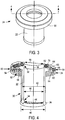
- Figures 3 and 4 illustrate the sleeve 22 and the seal member 24 of the ventricular pump coupling 20.
- the sleeve 22 has a center portion 3D, a first end 32 where the seal member 24 is attached, a second end 34 having a circumferential stop lip 36, and a central axis 38 substantially parallel to the center portion 30 of the sleeve 22.
- An outer diameter 40 of the circumferential stop lip 36 is greater than an outer diameter 42 of the center portion 30.
- an inner diameter 44 of the circumferential stop lip 36 is less than an inner diameter 46 of the center portion 30.
- An inner diameter 48 of the first end 32 of the sleeve 22 is slightly less than the inner diameter 46 of the center portion 30.
- the seal member 24 is attached to the first end 32 of the sleeve 22.
- the seal member 24 has a similar inner diameter to the first end 32 of the sleeve 22.
- the seal member 24 also has an outer diameter 50, and a central axis 38 that is coaxial with the central axis 38 of the sleeve 22.
- the seal member 24 and sleeve 22 are typically formed together from the same material in a single molding operation.
- the seal member 24 and sleeve 22 can be made of silicone or any other biocompatible material. A biocompatible coating can also be applied to the outer surface of the seal member 24.
- the seal member 24 has a ribbed surface 52 facing the second end 34 of the sleeve 22 for securing the seal member 24 position within a heart.
- the ribbed surface 52 of the seal member 24 has four circumferential grooves 54 forming the ribs.
- An individual rib has a first surface 56 substantially parallel to the central axis of the seal member and a second surface 58 angled relative to the central axis 38 of the seal member 24.
- the seal member 24 contains a first circumferential bore hole 60 within the seal member 24 in close proximity to the outer diameter 50 of the seal member 24, and a second circumferential bore hole 62 within the seal member 24 in close proximity to the inner diameter 48 of the seal member 24.
- First and second rectangular circumferential bores 64 and 66 are disposed between the first and second bore holes 60 and 62.
- the rectangular circumferential bores 64 and 66 are spaced apart from each other in a direction of the central axis 38.
- First and second circumferential coil springs 68 and 70 are disposed within each of the first and second circumferential bore holes 60 and 62 to actively expand the seal member 24 from a folded position to an open position.
- the introducer 26 is shown in an insertion position, the introducer 26 being made from laser-cut nitinol or stainless steel.
- the introducer 26 has a grip end 72, center portion 74, and an insertion end 76.
- the grip end 72 of the introducer 26 has a flared circumferential lip portion 78 having an inner diameter 80 and outer diameter 82.
- the lip portion 78 extends in a circumferentially radial direction perpendicular to a central axis 86 of the introducer 26, forming the outer diameter 82 of the grip end 72.
- the lip portion 78 curls slightly back in an inward direction toward the central axis 86 away from the outer diameter 82 of the grip end 72.
- the grip end 72 tapers inwardly from the lip portion 78 toward the center portion 74, having a constant inner diameter 84 less than the inner diameter 80 of the lip portion 78.
- the center portion 74 of the introducer 26 connects the grip end 72 to the insertion end 76.
- the insertion end 76 is comprised of a plurality of inwardly bent retractable fingers 88 extending from the center portion 74 of the introducer 26 in an axial direction.
- Each finger has a base segment 90, an intermediate segment 92, and a tip 94.
- the base segment 90 of a finger 88 is attached to the center portion 74 of the introducer 26 and is substantially parallel with the center portion 74.
- the intermediate segment 92 of a finger 88 is connected to the base segment 90 of the finger 88 at a first angle relative to the base segment 90 and center portion 74 of the introducer 26.
- the tip 94 of a finger 88 having a diameter and circular cross-section is positioned at an end of the intermediate segment 92.
- the plurality of fingers 88 and tips 94 in the aggregate form a circular arrangement having a diameter smaller than the inner diameter 84 of the center portion 74 of the introducer 26.
- the sleeve 22 of the seal member 24 is engaged with a conduit 96, made of titanium or any other relatively rigid material.
- the conduit 96 is inserted into the sleeve 22 in a co-axial relationship so that an inner wall 98 of the sleeve 22 and an outer wall 100 of the conduit 96 are engaged.
- the circumferential stop lip 36 engages the outer wall 100 of the conduit 96, through a friction fit, to prevent the sleeve 22 from sliding off the conduit 96.
- the introducer 26 is placed over the folded seal member 24 and sleeve 22 so that the introducer 26 is coaxial with the folded seal member 24 and sleeve 22.
- the grip end 72, center portion 74, and part of the fingers 88 surround the sleeve 22 of the seal member 24.
- the fingers 88 of the insertion end 76 of the introducer 26 engage the folded seal member 24 to prevent the circumferential coil springs 68 and 70 within the seal member 24 from expanding the folded seal member 24.
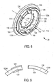
- the clamp component 28 is shown having an epicardial seal piece 104, a flange 106, a mounting piece 108, and a locking mechanism 110 all having a coaxial central axis 112 relative to one another.
- the epicardial seal piece 104 has an inner diameter 113 and an outer diameter 114 and is a polytetrafluoroethylene material or other biocompatible material suitable for suture.
- the flange 106 is made of stainless steel, or any other preferable material, and is attached to the epicardial seal piece 104 having an outer diameter 116 and an inner diameter 118 with a plurality of flange teeth 120.
- the inner diameter 118 of the flange 106 is substantially similar to the inner diameter 113 of the epicardial seal piece 104, so that top portions of the flange teeth 120 are substantially aligned with the inner diameter 113 of the epicardial seal piece 104.
- the rectangular-shaped mounting piece 108 is attached to the flange 106 by thermobonding or any other mechanical means, or may be bent out of a plane of the flange 106.
- the rectangular-shaped mounting piece 108 has two notches 122 and is slightly curved for easily attaching the locking mechanism 110.
- the locking mechanism 110 has a ratchet mechanism 124, rack teeth 126, and a lock body 128.
- the locking mechanism 110 can be polytetrafluoroethylene or any other suitable material.
- the lock body 128 has a circular shape with a rectangular cross-section.
- the lock body 128 has the ratchet mechanism 124 on one end 123 B and rack teeth 126 on the other end 123A.
- the rack teeth 126 are located on an inner circumferential surface of the lock body 128, with rack teeth 126 extending toward the central axis 112 of the clamp component 102.
- the ratchet mechanism 124 has ratchet teeth 130 facing radially outward from the central axis 112 to engage the rack teeth 126 when the rack teeth 126 are inserted into the ratchet mechanism 124.
- a force is provided to maintain the rack teeth 126 and the ratchet teeth 130 engaged with one another to provide a locking force.
- the diameter of the lock body 128 can be decreased by further movement of the rack teeth 126 into the ratchet mechanism 124.
- the decrease in diameter of the lock body 128 provides a clamping force on objects in contact with the lock body 128.
- the fully assembled coupling 20 has the seal member 24 and sleeve 22 attached to the end of the conduit 96, and the introducer 26 is located in a first position relative to the conduit 96, wherein the introducer 26 is placed over the seal member 24 to maintain the seal member 24 in a folded position.
- the clamp component 28 is then placed over the introducer 26 so that the clamp component 28, seal member 24, sleeve 22, and introducer 26 are coaxially arranged having a common central axis.
- an incision 132 is made in the wall of the left ventricle of the heart 134 before insertion of the fully assembled coupling connector 20.
- the insertion end 76 of the introducer 26 is aligned with the incision 132 made in the wall of the heart 134 prior to insertion into the heart 134.
- the tips 94 of the fingers 88 of the introducer 26 engage the incision 132 made in the heart 134, allowing for a majority of the fingers 88 and the folded seal member 24 to enter a left ventricle 136 upon a forward insertion movement.
- the introducer 26 is withdrawn to a second position in an axial direction away from the heart 134 and relative to the sleeve 22 and the conduit 96.
- the second position can be reached by a user applying an axial force to the grip end 72 of the introducer 26 to slide the introducer 26 to the second position until the introducer 26 engages the stop lip 36. Further movement of the introducer 26 is prevented by the stop lip 36, and the rigidity of the conduit that prevents inward deflection of the stop lip 36.
- the fingers 88 release the folded seal member 24, allowing the coil springs 68 and 70 embedded in the seal member 24 to expand from a folded position to an open position within the heart 134.
- the rib surface 52 of the seal member 24 engages an inner surface of the wall of the heart 134 upon expansion.
- the fingers 88 slide on the outer surface of the sleeve 22 of the seal member 24 to a final bent position.
- the fingers 88 then have a second angle between the intermediate segments 92 and base segments 90 of the fingers 88 that is less than the first angle between the intermediate segments 92 and base segments 90 in the first position of the introducer 26.
- the base segments 90 of the fingers 88 are no longer substantially parallel with the center portion 74 of the introducer 26.
- the base segments 90 of the fingers 88 now have an angle relative to the center portion 74 of the introducer 26.
- the fingers 88 form a triangular opening with the surface of the sleeve 22.
- the tips 94 are withdrawn from the left ventricle 136 of the heart 134, and are positioned between the flange 106 and the locking mechanism 110.
- the intermediate segments 92 extend at an angle relative to the central axis 86 of the introducer 26 from the tips 94 to a point away from the surface of the seal member sleeve 22, where the intermediate segment 92 connects to the base segment 90.
- the intermediate segments 92 also extend from the tips 94 in a direction away from the heart 134 at an angle relative to the central axis 86 of the introducer 26. A portion of each intermediate segment 92 is located under the locking mechanism 110 for engagement with the locking mechanism 110 when it is closed.
- the introducer 26 engages the stop lip 36 of the seal member 34 and sleeve 22 to prevent the introducer 26 from moving any further in the axial direction.
- the introducer 26 can also be rotated to a locked position to prevent axial movement when the introducer 26 has reached the second position.
- the locking mechanism 110 is then closed by inserting the rack teeth 126 into the ratchet mechanism 124 to decrease the diameter of the lock body 128.
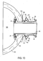
- the lock body 128 engages an angled top surface of the intermediate segments 92 to produce an axial force on the flange 106 and epicardial seal piece 104 in a direction of the heart 134.
- the axial force causes the wall of the left ventricle of the heart 134 to be clamped between the epicardial seal piece 104, located outside of the heart 134, and the ribbed surface 52 of the seal member 24, located inside of the left ventricle 136.
- the seal member 24 is in an open position within the left ventricle 136.
- the inner diameter 48 of the seal member 24 provides an opening for blood to flow into the left ventricle 136.
- the outer diameter 50 of the seal member 24 is greater than a cross-diameter of the incision 132 to ensure a tight seal.
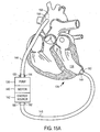
- a pump 138, motor 140, energy source 142, inflow tube 146, outflow tube 144, and connector 148 are provided for assisting a left ventricle of the heart 134.
- the pump 138 has an inlet 152 and an outlet 150, and the motor 140 is provided for driving the pump 138.
- the energy source 142 is also provided to operate the motor 140.
- the inflow tube 146 with a first end 162 and second end 160 are connected to the connector 148 to receive blood through the first end 162.
- the second end 160 of the inflow tube 146 is connected to the inlet 152 of the pump 138 to allow blood to flow to the pump 138 from the left ventricle 136.
- the outflow tube 144 also has a first end 156 and a second end 154.
- the first end 156 of the outflow tube 144 is connected to the outlet 156 of the pump 138, and the second end 154 of the outflow tube 144 is attached to the aorta 158 (the blood vessel leading out of the left ventricle 136).
- the outflow tube 144 receives blood from the outlet 150 of the pump 138 and delivers it to the aorta 158.
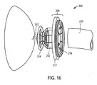
- Figure 16 illustrates a ventricular pump coupling 200, according to an alternative embodiment of the invention, including a sleeve 202, a seal member 204, a clamp component 208, and a conduit 210.
- the clamp component 208 includes an epicardial seal piece 212 and a flange 214.
- the flange 214 is formed together with and out of the same components as the sleeve 202 and the seal member 204.
- the epicardial seal piece 212 is then positioned over the seal member 204 and subsequently over the sleeve 202 until it contacts the flange 214.
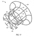
- Figure 17 illustrates a wire frame 216 forming part of the seal member 204, sleeve 202, and flange 214 shown in Figure 16 .
- the wire frame 216 includes a plurality (in this embodiment eight) of generally axially extending pieces 218, a plurality (in this embodiment two) of support rings 220, a plurality (in number, corresponding to the number of axially extending pieces 218) of distal clamping pieces 222, and a plurality (in number, equaling the number of axially extending pieces 218) of proximal clamping pieces 224.
- Each one of the axially extending pieces 218 is secured to both of the support rings 220, and the distal and proximal clamping pieces 222 and 224 are secured to the axially extending pieces 218.
- Each axially extending piece 218 is bent to have a respective sleeve piece 226, a respective flange piece 228, and a respective seal member piece 230.
- the seal member piece 230 has sections 232, 234, and 236.
- the section 232 extends toward a center line of the wire frame 216, the section 234 extends away from the center line, and the section 236 again extends toward the center line. Tips of the sections 236 almost contact one another.
- the distal clamping pieces 222 are secured at a location where the sections 234 and 236 meet. Although separated from one another, the distal clamping pieces 222 form a broken circle with a diameter that is only slightly larger than a diameter of one of the supporting rings 220.
- the proximal clamping pieces 224 are attached to ends of the flange pieces 228.
- the flange pieces 228 are curved outwardly, and the proximal clamping pieces 224 form a broken circle having a diameter that is much larger than a diameter formed by the distal clamping pieces 222.
- the wire frame 216 is typically made of stainless steel or another metal that is sufficiently rigid, but can be elastically or plastically deformed.
- the wire frame 216 is subsequently covered with a thin layer of silicone or other flexible and biocompatible material.
- the material typically has a thickness of between 0.2 and 1.0 mm.
- Another portion of the material and the sleeve pieces 226 form the sleeve 202 shown in Figure 16 .
- Another portion of the material together with the seal member pieces 230 form the seal member 204 shown in Figure 16 .
- the material forms only a small opening at tips of the sections 236 shown in Figure 17 .
- an incision 242 is formed in a wall of a heart, as was explained with reference to Figure 10 .
- the incision 242 is sufficiently large to allow for the seal member 204 and the sleeve 202 to be inserted into the heart.
- the epicardial seal piece 212 then contacts the outer wall of the heart.
- the conduit 210 is then inserted into the sleeve 202.
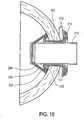
- Figure 18 illustrates movement of the seal member 204 after further insertion of the conduit 210.
- An outer diameter of the conduit 210 is larger than an opening provided by the sections 232. Movement of the conduit 210 to the left relative to the sleeve 202 moves the sections 232 out of the way so that they provide a larger opening for the conduit 210.
- the sections 234 and 236 rotate together with the sections 232 away from a center line of the conduit 210.
- the sections 234 rotate into contact with an inner surface of the wall of the heart. There is thus relative movement between the sections 234 and the flange 214 toward one another.
- the movement of the sections 234 toward the flange 214 enlarges a diameter of the seal member 204 and clamps the wall of the heart between the seal member 204 and the flange 214. Because the sections 236 rotate away from a center line of the conduit 210, the opening provided between tips of the sections 236 enlarges, to allow for blood to flow therethrough. Suturing can be provided to further secure the epicardial seal piece 212 to the wall of the heart.
Landscapes
- Health & Medical Sciences (AREA)
- Heart & Thoracic Surgery (AREA)
- Engineering & Computer Science (AREA)
- Life Sciences & Earth Sciences (AREA)
- Cardiology (AREA)
- General Health & Medical Sciences (AREA)
- Veterinary Medicine (AREA)
- Biomedical Technology (AREA)
- Public Health (AREA)
- Animal Behavior & Ethology (AREA)
- Mechanical Engineering (AREA)
- Anesthesiology (AREA)
- Hematology (AREA)
- Surgery (AREA)
- Molecular Biology (AREA)
- Medical Informatics (AREA)
- Nuclear Medicine, Radiotherapy & Molecular Imaging (AREA)
- Vascular Medicine (AREA)
- External Artificial Organs (AREA)
- Prostheses (AREA)
Description
- This invention relates to a ventricular pump coupling device that provides a tight seal between the left ventricle of a heart and a conduit.
- Ventricular assist devices are mechanical devices that are used to assist or replace cardiac functions. These devices are capable of partially or completely replacing the functioning of a failing heart.
- The heart is located in the thoracic cavity and is generally partitioned into the left and right half. Each half consists of an atrium and a ventricle. The ventricles are described as the left ventricle or right ventricle. Likewise, the atria are described as the left atrium and right atrium. The wall of each ventricle is comprised of three layers of tissue: the endocardium, the myocardium, and the epicardium. The endocardium is the tissue on the inner layer of the ventricle, while the epicardium is the tissue on the outer layer of the ventricle functioning as a protective layer. The myocardium is essentially the middle layer of tissue between the endocardium and epicardium.
- In order to implement a ventricular assist device, a connection must be made to the left ventricle of the heart through the three layers of tissue, to enable blood flow to the ventricle cavity.
- The connection to the left ventricle can be achieved through the use of a connection device. In one example, a connection such as screw-type connectors can be used, where the user must core a hole into the heart and place sutures around the hole to insert a cuff to be secured by suturing. A tube is then inserted into the sutured cuff and a tie-down may be required around the outer diameter of the cuff to hold the tube in place.
- One of the problems with this method is that the screw-type procedure is work-intensive and requires extensive suturing. Even when a cuff is sutured in place, there is no guarantee that the connection between the tube and the cuff is adequately sealed and reliable.
- Furthermore, the screw-type procedure damages the tissue layers of the left ventricle and may interfere with the contraction and functioning of the left ventricle. The procedure also requires that a portion of the myocardium be removed, which may affect the functioning of the heart.
- Further
US 2005/0209502 A1 teaches a device for connecting a cardiac biventricular assist means disclosing different options of mounting and fixing insertion part in port of the septum. The document also discloses a receiving part that gets attached to the insertion part by means of sawtooth profiles on the receiving part and the insertion part. -
US 2004/0097993 A1 also gives an advanced anastomosis system, which discloses grommet designs with end side fittings. The end side fittings comprise an support device attached to a base, and petals compressible into a reduced diameter. Once the petals are inserted into a host vessel, the petals return towards their resting position, compressing the host vessel wall against the support device. - The invention provides a device adapted for creating a sealed connection at an opening in a wall of a heart, comprising a conduit, having an end and a central axis in an axial direction for fluid to flow therethrough, a sleeve, a seal member attached to a first end of the sleeve, the seal member having a ribbed surface facing a second end of the sleeve, the sleeve being engaged with the conduit configured for moving between a folded position, wherein the ribbed surface is configured to be folded so as to pass through the opening of the wall of the heart, and radially away from the central axis to an open position wherein the seal member is configured to expand so that the seal member has a cross-dimension that is larger than a cross-dimension of the opening in the wall of the heart with the ribbed surface configured to face the inner wall of the heart and be positioned around the opening of the heart, and a clamp component to be positioned outside of the heart, the seal member and the clamp component being movable relative to one another to produce an axial clamping force with the wall of the heart between the clamp component and the seal member so that a seal is created between the seal member and the wall of the heart.
- The device further comprises an introducer being secured for movement between first and second positions relative to the conduit, in the first position, the introducer maintaining the seal member in the folded position to allow for insertion of the seal member through the opening into the heart and, in the second position, the introducer allowing for expansion of the seal member so that the seal member has a cross-dimension that is larger than a cross-dimension of the opening in the wall of the heart. The introducer further has at least one segment at an angle relative to the central axis.
- The device also comprises a clamp component adapted to be positioned outside of the heart, wherein the clamp component has an epicardial seal piece having an inner and outer diameter adapted to engage the wall of the heart, a flange attached to the epicardial seal piece and a mounting piece attached to the flange, and a locking mechanism.
- Further, the locking mechanism has a lock body that is attached to the mounting piece and radially movable in a radial direction from a position distant from the central axis to a position closer to the central axis, and means for moving the lock body in the radial direction, wherein the lock body engages an angled top surface of the intermediate segments to produce an axial force on the flange, wherein said radial movement of the lock body creates an axial force on the clamping component, the clamp component being configured to to produce a clamping force in the axial direction with the wall of the heart between the clamp component and the seal member so that a seal is created between the ribbed surface of the seal member and an inner wall of the heart.
- The seal member has a ribbed surface to engage the wall of the heart.
- The device may further comprise at least one expansion spring within the seal member to expand the seal member within the heart, wherein the seal member may be molded silicone having a biocompatible coating.
- The introducer may have retractable fingers, and may be rotatable into a locked position to prevent movement of the introducer in the axial direction relative to the conduit. The introducer may also be tapered on one end and may be slideably engaged with a stop on the seal member to prevent movement of the introducer in the axial direction relative to the conduit.
- The introducer may be selected from at least one of nitinol or stainless steel.
- The introducer may passively allow the seal member to expand to an open position, and may expand under a spring force.
- The device may further comprise a wire frame, plastic deformation of at least a portion of the wire frame causing expansion of the seal member. Movement of the conduit relative to the wire frame may cause deformation of the portion of the wire frame.
- The clamp component may have an epicardial seal piece having an inner and outer diameter to engage the wall of the heart, and may have a flange being attached to the epicardial seal piece. The clamp component may also have a mounting piece being attached to the flange, and the locking mechanism attached to the mounting piece.
- The locking mechanism may have a plurality of teeth to close the locking mechanism, the locking mechanism engaging the introducer and the flange to produce the axial clamping force. The locking mechanism may be polytetrafluoroethylene.
- The flange may have an outer diameter and an inner diameter having a plurality of teeth.
- It is further disclosed a method for creating a sealed connection at an opening in a wall of a heart, including inserting an introducer and a seal member, in a folded position, through an opening in the wall of the heart, expanding the seal member to an open position within the heart so that the seal member has a cross-dimension that is larger than a cross-dimension of the opening in the wall of the heart, and moving a clamp component relative to the seal member to create an axial clamping force with the wall of the heart between the clamp component and the seal member so that a seal is created between the seal member and the wall of the heart.
- The invention is described by way of examples with reference to the accompanying drawings, wherein:
-
Figure 1 is an perspective view of the ventricular pump coupling assembly, according to one embodiment of the invention; -
Figure 2 is a cross-sectional side view taken on 2-2 ofFigure 1 ; -
Figure 3 is a perspective view of a seal member forming part of the ventricular pump coupling; -
Figure 4 is a cross-sectional front view taken on 4-4 ofFigure 3 ; -
Figure 5 is a cross-sectional side view of an introducer forming part of the ventricular pump coupling; -
Figure 6 is a perspective view of the seal member, a sleeve, the introducer, and a conduit forming a partial assembly of the ventricular pump coupling; -
Figure 7 is a cross-sectional side view taken on 7-7 ofFigure 6 ; -
Figure 8 is a perspective view of a clamp component forming part of the ventricular pump coupling, wherein a locking mechanism is in an open position; -
Figure 9 illustrates a ratchet mechanism and rack teeth of the locking mechanism in an open position; -
Figure 10 is a perspective view of the ventricular pump coupling assembly before insertion into an incision in the heart; -
Figure 11 is a cross-sectional side view of the ventricular pump coupling assembly after insertion into an incision in the heart, with the introducer in a first position; -
Figure 12 is a cross-sectional side view similar toFigure 11 , illustrating the ventricular pump coupling assembly wherein the introducer is moved to a second position and the seal member is in an open position; -
Figure 13 is a cross-sectional side view similar toFigure 12 , illustrating the ventricular pump coupling assembly wherein the locking mechanism is closed and an axial force is produced; -
Figure 14 is a perspective view of the seal member in an open position within the left ventricle cavity of the heart; -
Figures 15A and15B are system drawings illustrating a device assisting the left ventricle of the heart; -
Figure 16 is a perspective view illustrating a ventricular pump coupling assembly, according to an alternative embodiment of the invention; -
Figure 17 is a perspective view illustrating a wire frame forming part of the coupling ofFigure 16 ; and -
Figure 18 illustrates how the coupling attaches to a wall of a heart. -
Figures 3 and 4 illustrate thesleeve 22 and theseal member 24 of theventricular pump coupling 20. Thesleeve 22 has a center portion 3D, afirst end 32 where theseal member 24 is attached, asecond end 34 having acircumferential stop lip 36, and acentral axis 38 substantially parallel to thecenter portion 30 of thesleeve 22. Anouter diameter 40 of thecircumferential stop lip 36 is greater than anouter diameter 42 of thecenter portion 30. Furthermore, aninner diameter 44 of thecircumferential stop lip 36 is less than aninner diameter 46 of thecenter portion 30. Aninner diameter 48 of thefirst end 32 of thesleeve 22 is slightly less than theinner diameter 46 of thecenter portion 30. - The
seal member 24 is attached to thefirst end 32 of thesleeve 22. Theseal member 24 has a similar inner diameter to thefirst end 32 of thesleeve 22. Theseal member 24 also has anouter diameter 50, and acentral axis 38 that is coaxial with thecentral axis 38 of thesleeve 22. Theseal member 24 andsleeve 22 are typically formed together from the same material in a single molding operation. Theseal member 24 andsleeve 22 can be made of silicone or any other biocompatible material. A biocompatible coating can also be applied to the outer surface of theseal member 24. - Referring to
Figure 4 , theseal member 24 has a ribbedsurface 52 facing thesecond end 34 of thesleeve 22 for securing theseal member 24 position within a heart. Theribbed surface 52 of theseal member 24 has fourcircumferential grooves 54 forming the ribs. An individual rib has afirst surface 56 substantially parallel to the central axis of the seal member and asecond surface 58 angled relative to thecentral axis 38 of theseal member 24. - Furthermore, as shown in
Figure 4 , theseal member 24 contains a firstcircumferential bore hole 60 within theseal member 24 in close proximity to theouter diameter 50 of theseal member 24, and a secondcircumferential bore hole 62 within theseal member 24 in close proximity to theinner diameter 48 of theseal member 24. First and second rectangular circumferential bores 64 and 66 are disposed between the first and second bore holes 60 and 62. The rectangular circumferential bores 64 and 66 are spaced apart from each other in a direction of thecentral axis 38. First and second circumferential coil springs 68 and 70 are disposed within each of the first and second circumferential bore holes 60 and 62 to actively expand theseal member 24 from a folded position to an open position. - As shown in
Figure 5 , theintroducer 26 is shown in an insertion position, theintroducer 26 being made from laser-cut nitinol or stainless steel. Theintroducer 26 has agrip end 72,center portion 74, and aninsertion end 76. Thegrip end 72 of theintroducer 26 has a flaredcircumferential lip portion 78 having aninner diameter 80 andouter diameter 82. Thelip portion 78 extends in a circumferentially radial direction perpendicular to acentral axis 86 of theintroducer 26, forming theouter diameter 82 of thegrip end 72. Thelip portion 78 curls slightly back in an inward direction toward thecentral axis 86 away from theouter diameter 82 of thegrip end 72. Thegrip end 72 tapers inwardly from thelip portion 78 toward thecenter portion 74, having a constantinner diameter 84 less than theinner diameter 80 of thelip portion 78. Thecenter portion 74 of theintroducer 26 connects thegrip end 72 to theinsertion end 76. - The
insertion end 76 is comprised of a plurality of inwardly bentretractable fingers 88 extending from thecenter portion 74 of theintroducer 26 in an axial direction. Each finger has abase segment 90, anintermediate segment 92, and atip 94. Thebase segment 90 of afinger 88 is attached to thecenter portion 74 of theintroducer 26 and is substantially parallel with thecenter portion 74. Theintermediate segment 92 of afinger 88 is connected to thebase segment 90 of thefinger 88 at a first angle relative to thebase segment 90 andcenter portion 74 of theintroducer 26. Thetip 94 of afinger 88 having a diameter and circular cross-section is positioned at an end of theintermediate segment 92. The plurality offingers 88 andtips 94 in the aggregate form a circular arrangement having a diameter smaller than theinner diameter 84 of thecenter portion 74 of theintroducer 26. - As shown in
Figure 6 , during assembly, thesleeve 22 of theseal member 24 is engaged with aconduit 96, made of titanium or any other relatively rigid material. As further shown inFigure 7 , theconduit 96 is inserted into thesleeve 22 in a co-axial relationship so that aninner wall 98 of thesleeve 22 and anouter wall 100 of theconduit 96 are engaged. Thecircumferential stop lip 36 engages theouter wall 100 of theconduit 96, through a friction fit, to prevent thesleeve 22 from sliding off theconduit 96. - The
introducer 26 is placed over the foldedseal member 24 andsleeve 22 so that theintroducer 26 is coaxial with the foldedseal member 24 andsleeve 22. Thegrip end 72,center portion 74, and part of thefingers 88 surround thesleeve 22 of theseal member 24. Thefingers 88 of theinsertion end 76 of theintroducer 26 engage the foldedseal member 24 to prevent the circumferential coil springs 68 and 70 within theseal member 24 from expanding the foldedseal member 24. - Referring to
Figure 8 , theclamp component 28 is shown having anepicardial seal piece 104, aflange 106, a mountingpiece 108, and alocking mechanism 110 all having a coaxialcentral axis 112 relative to one another. Theepicardial seal piece 104 has aninner diameter 113 and anouter diameter 114 and is a polytetrafluoroethylene material or other biocompatible material suitable for suture. Theflange 106 is made of stainless steel, or any other preferable material, and is attached to theepicardial seal piece 104 having anouter diameter 116 and aninner diameter 118 with a plurality offlange teeth 120. Theinner diameter 118 of theflange 106 is substantially similar to theinner diameter 113 of theepicardial seal piece 104, so that top portions of theflange teeth 120 are substantially aligned with theinner diameter 113 of theepicardial seal piece 104. - The rectangular-shaped
mounting piece 108 is attached to theflange 106 by thermobonding or any other mechanical means, or may be bent out of a plane of theflange 106. The rectangular-shapedmounting piece 108 has twonotches 122 and is slightly curved for easily attaching thelocking mechanism 110. - The
locking mechanism 110 has aratchet mechanism 124, rackteeth 126, and alock body 128. Thelocking mechanism 110 can be polytetrafluoroethylene or any other suitable material. Thelock body 128 has a circular shape with a rectangular cross-section. Thelock body 128 has theratchet mechanism 124 on oneend 123 B and rackteeth 126 on theother end 123A. Therack teeth 126 are located on an inner circumferential surface of thelock body 128, withrack teeth 126 extending toward thecentral axis 112 of the clamp component 102. - As shown in
Figure 9 , theratchet mechanism 124 has ratchetteeth 130 facing radially outward from thecentral axis 112 to engage therack teeth 126 when therack teeth 126 are inserted into theratchet mechanism 124. A force is provided to maintain therack teeth 126 and theratchet teeth 130 engaged with one another to provide a locking force. - When the
locking mechanism 110 is in a closed position with therack teeth 126 engaging theratchet mechanism 124, the diameter of thelock body 128 can be decreased by further movement of therack teeth 126 into theratchet mechanism 124. The decrease in diameter of thelock body 128 provides a clamping force on objects in contact with thelock body 128. - Referring again to
Figure 2 , the fully assembledcoupling 20 has theseal member 24 andsleeve 22 attached to the end of theconduit 96, and theintroducer 26 is located in a first position relative to theconduit 96, wherein
theintroducer 26 is placed over theseal member 24 to maintain theseal member 24 in a folded position. Theclamp component 28 is then placed over theintroducer 26 so that theclamp component 28,seal member 24,sleeve 22, andintroducer 26 are coaxially arranged having a common central axis. - In use, referring to
Figure 10 , anincision 132 is made in the wall of the left ventricle of theheart 134 before insertion of the fully assembledcoupling connector 20. Theinsertion end 76 of theintroducer 26 is aligned with theincision 132 made in the wall of theheart 134 prior to insertion into theheart 134. - As shown in
Figure 11 , thetips 94 of thefingers 88 of theintroducer 26 engage theincision 132 made in theheart 134, allowing for a majority of thefingers 88 and the foldedseal member 24 to enter aleft ventricle 136 upon a forward insertion movement. - A shown in
Figure 12 , theintroducer 26 is withdrawn to a second position in an axial direction away from theheart 134 and relative to thesleeve 22 and theconduit 96. The second position can be reached by a user applying an axial force to the grip end 72 of theintroducer 26 to slide theintroducer 26 to the second position until theintroducer 26 engages thestop lip 36. Further movement of theintroducer 26 is prevented by thestop lip 36, and the rigidity of the conduit that prevents inward deflection of thestop lip 36. - As the
introducer 26 is moved to the second position, thefingers 88 release the foldedseal member 24, allowing the coil springs 68 and 70 embedded in theseal member 24 to expand from a folded position to an open position within theheart 134. Therib surface 52 of theseal member 24 engages an inner surface of the wall of theheart 134 upon expansion. Thefingers 88 slide on the outer surface of thesleeve 22 of theseal member 24 to a final bent position. Thefingers 88 then have a second angle between theintermediate segments 92 andbase segments 90 of thefingers 88 that is less than the first angle between theintermediate segments 92 andbase segments 90 in the first position of theintroducer 26. Moreover, in the second position, thebase segments 90 of thefingers 88 are no longer substantially parallel with thecenter portion 74 of theintroducer 26. Thebase segments 90 of thefingers 88 now have an angle relative to thecenter portion 74 of theintroducer 26. - The
fingers 88 form a triangular opening with the surface of thesleeve 22. Thetips 94 are withdrawn from theleft ventricle 136 of theheart 134, and are positioned between theflange 106 and thelocking mechanism 110. Theintermediate segments 92 extend at an angle relative to thecentral axis 86 of theintroducer 26 from thetips 94 to a point away from the surface of theseal member sleeve 22, where theintermediate segment 92 connects to thebase segment 90. Theintermediate segments 92 also extend from thetips 94 in a direction away from theheart 134 at an angle relative to thecentral axis 86 of theintroducer 26. A portion of eachintermediate segment 92 is located under thelocking mechanism 110 for engagement with thelocking mechanism 110 when it is closed. - As mentioned, the
introducer 26 engages thestop lip 36 of theseal member 34 andsleeve 22 to prevent theintroducer 26 from moving any further in the axial direction. Theintroducer 26 can also be rotated to a locked position to prevent axial movement when theintroducer 26 has reached the second position. - As shown in
Figure 13 , after theintroducer 26 has reached the second position, thelocking mechanism 110 is then closed by inserting therack teeth 126 into theratchet mechanism 124 to decrease the diameter of thelock body 128. As the diameter of thelock body 128 decreases, thelock body 128 engages an angled top surface of theintermediate segments 92 to produce an axial force on theflange 106 andepicardial seal piece 104 in a direction of theheart 134. The axial force causes the wall of the left ventricle of theheart 134 to be clamped between theepicardial seal piece 104, located outside of theheart 134, and theribbed surface 52 of theseal member 24, located inside of theleft ventricle 136. - Referring to
Figure 14 , theseal member 24 is in an open position within theleft ventricle 136. Theinner diameter 48 of theseal member 24 provides an opening for blood to flow into theleft ventricle 136. Theouter diameter 50 of theseal member 24 is greater than a cross-diameter of theincision 132 to ensure a tight seal. - As shown in
Figures 15A and15B , apump 138,motor 140,energy source 142,inflow tube 146,outflow tube 144, andconnector 148 are provided for assisting a left ventricle of theheart 134. Thepump 138 has aninlet 152 and anoutlet 150, and themotor 140 is provided for driving thepump 138. Theenergy source 142 is also provided to operate themotor 140. Theinflow tube 146 with afirst end 162 andsecond end 160 are connected to theconnector 148 to receive blood through thefirst end 162. Thesecond end 160 of theinflow tube 146 is connected to theinlet 152 of thepump 138 to allow blood to flow to thepump 138 from theleft ventricle 136. - The
outflow tube 144 also has afirst end 156 and asecond end 154. Thefirst end 156 of theoutflow tube 144 is connected to theoutlet 156 of thepump 138, and thesecond end 154 of theoutflow tube 144 is attached to the aorta 158 (the blood vessel leading out of the left ventricle 136). Theoutflow tube 144 receives blood from theoutlet 150 of thepump 138 and delivers it to theaorta 158. -
Figure 16 illustrates aventricular pump coupling 200, according to an alternative embodiment of the invention, including asleeve 202, aseal member 204, aclamp component 208, and aconduit 210. - The
clamp component 208 includes anepicardial seal piece 212 and aflange 214. Theflange 214 is formed together with and out of the same components as thesleeve 202 and theseal member 204. Theepicardial seal piece 212 is then positioned over theseal member 204 and subsequently over thesleeve 202 until it contacts theflange 214. -
Figure 17 illustrates awire frame 216 forming part of theseal member 204,sleeve 202, andflange 214 shown inFigure 16 . Thewire frame 216 includes a plurality (in this embodiment eight) of generally axially extendingpieces 218, a plurality (in this embodiment two) of support rings 220, a plurality (in number, corresponding to the number of axially extending pieces 218) ofdistal clamping pieces 222, and a plurality (in number, equaling the number of axially extending pieces 218) ofproximal clamping pieces 224. Each one of theaxially extending pieces 218 is secured to both of the support rings 220, and the distal andproximal clamping pieces axially extending pieces 218. - Each axially extending
piece 218 is bent to have arespective sleeve piece 226, arespective flange piece 228, and a respectiveseal member piece 230. Theseal member piece 230 hassections section 232 extends toward a center line of thewire frame 216, thesection 234 extends away from the center line, and thesection 236 again extends toward the center line. Tips of thesections 236 almost contact one another. - The
distal clamping pieces 222 are secured at a location where thesections distal clamping pieces 222 form a broken circle with a diameter that is only slightly larger than a diameter of one of the supporting rings 220. - The
proximal clamping pieces 224 are attached to ends of theflange pieces 228. Theflange pieces 228 are curved outwardly, and theproximal clamping pieces 224 form a broken circle having a diameter that is much larger than a diameter formed by thedistal clamping pieces 222. - The
wire frame 216 is typically made of stainless steel or another metal that is sufficiently rigid, but can be elastically or plastically deformed. - The
wire frame 216 is subsequently covered with a thin layer of silicone or other flexible and biocompatible material. The material typically has a thickness of between 0.2 and 1.0 mm. A portion of the material, together with theflange pieces 228 andproximal clamping pieces 224, form theflange 214 shown inFigure 16 . Another portion of the material and thesleeve pieces 226 form thesleeve 202 shown inFigure 16 . Another portion of the material together with theseal member pieces 230 form theseal member 204 shown inFigure 16 . The material forms only a small opening at tips of thesections 236 shown inFigure 17 . - Referring again specifically to
Figure 16 , anincision 242 is formed in a wall of a heart, as was explained with reference toFigure 10 . Theincision 242 is sufficiently large to allow for theseal member 204 and thesleeve 202 to be inserted into the heart. Theepicardial seal piece 212 then contacts the outer wall of the heart. Theconduit 210 is then inserted into thesleeve 202. -
Figure 18 illustrates movement of theseal member 204 after further insertion of theconduit 210. An outer diameter of theconduit 210 is larger than an opening provided by thesections 232. Movement of theconduit 210 to the left relative to thesleeve 202 moves thesections 232 out of the way so that they provide a larger opening for theconduit 210. Thesections sections 232 away from a center line of theconduit 210. Thesections 234 rotate into contact with an inner surface of the wall of the heart. There is thus relative movement between thesections 234 and theflange 214 toward one another. The movement of thesections 234 toward theflange 214 enlarges a diameter of theseal member 204 and clamps the wall of the heart between theseal member 204 and theflange 214. Because thesections 236 rotate away from a center line of theconduit 210, the opening provided between tips of thesections 236 enlarges, to allow for blood to flow therethrough. Suturing can be provided to further secure theepicardial seal piece 212 to the wall of the heart. - While certain exemplary embodiments have been described and shown in the accompanying drawings, it is to be understood that such embodiments are merely illustrative and not restrictive of the current invention, and that this invention is not restricted to the specific constructions and arrangements shown and described since modifications may occur to those ordinarily skilled in the art.
Claims (12)
- A device (20) adapted for creating a sealed connection at an opening (132) in a wall of a heart (134), comprising:a conduit (96) having an end (32) and a central axis (38) in an axial direction for fluid to flow therethrough;a sleeve (22);a seal member (24) attached to a first end (32) of the sleeve (22), the seal member (24) having a ribbed surface (54) facing a second end (34) of the sleeve (22), the sleeve (22) being engaged with the conduit (96), the seal member (24) configured for moving between a folded position, wherein the ribbed surface (54) is configured to be folded so as to pass through the opening of the wall of the heart, and radially away from the central axis to an open position wherein the seal member (24) is configured to be expanded so that the seal member (24) has a cross-dimension that is larger than a cross-dimension of the opening in the wall of the heart (134) with the ribbed surface (54) configured to face the inner wall of the heart (134) and to be positioned around the opening of the wall of the heart (134);
an introducer (26) configured to be secured for movement between the first and second positions relative to the conduit (96), in the first position, the introducer configured for maintaining the seal member (24) in the folded position to allow for insertion of the seal member (24) through the opening in the wall of the heart (134) and, in the second position, the introducer (26) configured for allowing for expansion of the seal member (24) so that the seal member (24) has a cross-dimension that is larger than a cross-dimension of the opening in the wall of the heart (134),the introducer (26) having at least one segment (92) at an angle relative to the central axis (38);a clamp component (28) adapted to be positioned outside of the heart, wherein the clamp component (28) has an epicardial seal piece (104) having an inner (118) and outer (116) diameter adapted to engage the wall of the heart (134), a flange (106) attached to the epicardial seal piece (104) and a mounting piece (108) attached to the flange (106); anda locking mechanism (110),characterized in that the locking mechanism (110) has a lock body (128) that is attached to the mounting piece (108) and radially movable in a radial direction from a position distant from the central axis (38) to a position closer to the central axis (38), and means (120) for moving the lock body (128) in the radial direction, wherein the lock body (128) engages an angled top surface of the intermediate segments (92) to produce an axial force on the flange (106), wherein said radial movement of the lock body (128) creates an axial force on the clamp component (28), the clamp component (28) being configured to produce a clamping force in the axial direction with the wall of the heart (134) between the clamp component (28) and the seal member (24) so that a seal is created between the ribbed surface (54) of the seal member (24) and an inner wall of the heart (134). - A device as claimed in claim 1, further comprising at least one expansion spring (68, 70) within the seal member (24) adapted to expand the seal member (24) within the heart.
- A device as claimed in any one of claims 1 or 2, wherein the seal member (24) is molded silicone having a biocompatible coating.
- A device as claimed in any one of claims 1 to 3, wherein the introducer (26) has retractable fingers (88), wherein each finger (88) has a respective segment (92) at an angle relative to the central axis (38).
- A device as claimed in any one of claims 1 to 4, wherein the introducer (26) is rotatable into a locked position to prevent movement of the introducer (26) in the axial direction relative to the conduit (96).
- A device as claimed in any one of claims 1 to 5, wherein the introducer (26) is tapered on one end (94) and is slideably engaged with a stop (36) on the seal member (24) to prevent movement of the introducer (26) in the axial direction relative to the conduit (96).
- A device as claimed in any one of claims 1 to 6, wherein the introducer (26) is selected from at least one of nitinol or stainless steel.
- A device as claimed in any one of claims 1 to 7, wherein the introducer (26) is configured to passively allow the seal member (24) to expand to an open position.
- A device as claimed in claim 8, wherein the seal member (24) is configured to expand under a spring force.
- A device as claimed in any one of claims 1 to 9, wherein the locking mechanism has a plurality of teeth (120) to close the locking mechanism, the locking mechanism engaging the flange (106) to produce the radial movement of the locking mechanism causing the locking mechanism to produce the axial clamping force.
- A device as claimed in any one of claims 1 to 10, wherein the locking mechanism is polytetrafluoroethylene.
- A device as claimed in any one of claims 1 to 11, wherein the flange (106) has an outer diameter (114) and an inner diameter (113) having a plurality of teeth (120).
Applications Claiming Priority (3)
| Application Number | Priority Date | Filing Date | Title |
|---|---|---|---|
| US72844105P | 2005-10-19 | 2005-10-19 | |
| US11/582,721 US8343028B2 (en) | 2005-10-19 | 2006-10-17 | Ventricular pump coupling |
| PCT/US2006/041054 WO2007047933A2 (en) | 2005-10-19 | 2006-10-19 | Ventricular pump coupling |
Publications (3)
| Publication Number | Publication Date |
|---|---|
| EP1948035A2 EP1948035A2 (en) | 2008-07-30 |
| EP1948035A4 EP1948035A4 (en) | 2013-03-13 |
| EP1948035B1 true EP1948035B1 (en) | 2019-09-18 |
Family
ID=37963321
Family Applications (1)
| Application Number | Title | Priority Date | Filing Date |
|---|---|---|---|
| EP06817222.0A Not-in-force EP1948035B1 (en) | 2005-10-19 | 2006-10-19 | Ventricular pump coupling |
Country Status (5)
| Country | Link |
|---|---|
| US (2) | US8343028B2 (en) |
| EP (1) | EP1948035B1 (en) |
| AU (1) | AU2006304742B2 (en) |
| CA (1) | CA2626631C (en) |
| WO (1) | WO2007047933A2 (en) |
Families Citing this family (63)
| Publication number | Priority date | Publication date | Assignee | Title |
|---|---|---|---|---|
| US9138228B2 (en) | 2004-08-11 | 2015-09-22 | Emory University | Vascular conduit device and system for implanting |
| US7846123B2 (en) | 2007-04-24 | 2010-12-07 | Emory University | Conduit device and system for implanting a conduit device in a tissue wall |
| US8409228B2 (en) | 2008-06-06 | 2013-04-02 | Duane D. Blatter | Tissue management methods, apparatus, and systems |
| CA2725783C (en) * | 2008-06-19 | 2017-07-11 | Convatec Technologies Inc. | Ostomy appliances for directing effluent output |
| US8337465B2 (en) | 2009-01-29 | 2012-12-25 | Vital Access Corporation | Subcutaneous vascular access ports and related systems, methods, and implantation features |
| US11197952B2 (en) | 2009-01-29 | 2021-12-14 | Advent Access Pte. Ltd. | Vascular access ports and related methods |
| US9179901B2 (en) | 2009-01-29 | 2015-11-10 | Vital Access Corporation | Vascular access ports and related methods |
| US20110118833A1 (en) * | 2009-11-15 | 2011-05-19 | Thoratec Corporation | Attachment device and method |
| US20110118829A1 (en) * | 2009-11-15 | 2011-05-19 | Thoratec Corporation | Attachment device and method |
| WO2011069154A2 (en) * | 2009-12-05 | 2011-06-09 | Integrated Sensing Systems, Inc. | Delivery system, method, and anchor for medical implant placement |
| US8715300B2 (en) * | 2009-12-05 | 2014-05-06 | Integrated Sensing Systems, Inc. | Delivery system, method, and anchor for medical implant placement |
| US8152845B2 (en) * | 2009-12-30 | 2012-04-10 | Thoratec Corporation | Blood pump system with mounting cuff |
| CN103228300A (en) * | 2010-09-07 | 2013-07-31 | 保罗·A·斯彭斯 | Intubation Systems and Methods |
| WO2012051454A2 (en) | 2010-10-13 | 2012-04-19 | Thoratec Corporation | Pumping blood |
| AU2012211082B2 (en) | 2011-01-28 | 2015-11-05 | Apica Cardiovascular Limited | Systems for sealing a tissue wall puncture |
| AU2012212215B2 (en) | 2011-02-01 | 2015-07-30 | Emory University | Systems for implanting and using a conduit within a tissue wall |
| EP2677943B1 (en) | 2011-02-25 | 2016-08-31 | Thoratec Corporation | Coupling system for connecting a conduit to biological tissue |
| JP6039586B2 (en) | 2011-03-02 | 2016-12-07 | ソーラテック コーポレイション | Ventricular cuff |
| WO2013056131A1 (en) | 2011-10-13 | 2013-04-18 | Reichenbach Steven H | Pump and method for mixed flow blood pumping |
| US8579790B2 (en) | 2012-01-05 | 2013-11-12 | Thoratec Corporation | Apical ring for ventricular assist device |
| US9199019B2 (en) | 2012-08-31 | 2015-12-01 | Thoratec Corporation | Ventricular cuff |
| US9981076B2 (en) | 2012-03-02 | 2018-05-29 | Tc1 Llc | Ventricular cuff |
| EP2822614B1 (en) | 2012-03-05 | 2016-12-28 | Thoratec Corporation | Modular implantable medical pump |
| WO2013162741A1 (en) | 2012-04-23 | 2013-10-31 | Thoratec Corporation | Engagement device and method for deployment of anastomotic clips |
| DE102013208433A1 (en) * | 2012-05-25 | 2013-11-28 | Robert Bosch Gmbh | Power tool |
| EP2908880B1 (en) | 2012-10-16 | 2018-12-05 | Paul A. Spence | Devices for facilitating flow from the heart to a blood pump |
| WO2014117087A1 (en) * | 2013-01-25 | 2014-07-31 | Apica Cardiovascular Limited | Systems and methods for percutaneous access, stabilization and closure of organs |
| WO2014144085A1 (en) * | 2013-03-15 | 2014-09-18 | Apk Advanced Medical Technologies, Inc. | Devices, systems, and methods for implanting and using a connnector in a tissue wall |
| US9808283B2 (en) | 2013-12-04 | 2017-11-07 | Heartware, Inc. | Apparatus and methods for cutting an atrial wall |
| WO2015134944A1 (en) * | 2014-03-06 | 2015-09-11 | Thoratec Corporation | Ventricular cuff |
| WO2016053688A1 (en) | 2014-10-01 | 2016-04-07 | Heartware, Inc. | Backup controller system with updating |
| US10485909B2 (en) | 2014-10-31 | 2019-11-26 | Thoratec Corporation | Apical connectors and instruments for use in a heart wall |
| US10724534B2 (en) | 2014-11-26 | 2020-07-28 | Tc1 Llc | Pump and method for mixed flow blood pumping |
| US9821101B2 (en) | 2014-12-10 | 2017-11-21 | Heartware, Inc. | Cardiac pump implantation device and method |
| WO2016152465A1 (en) * | 2015-03-26 | 2016-09-29 | 株式会社小糸製作所 | Vehicular lamp device and lamp device system |
| EP3436105B1 (en) | 2016-03-30 | 2021-04-28 | Heartware, Inc. | Flanged heart tissue blocker |
| WO2018017716A1 (en) | 2016-07-21 | 2018-01-25 | Tc1 Llc | Rotary seal for cantilevered rotor pump and methods for axial flow blood pumping |
| US10660998B2 (en) | 2016-08-12 | 2020-05-26 | Tci Llc | Devices and methods for monitoring bearing and seal performance |
| US10894116B2 (en) | 2016-08-22 | 2021-01-19 | Tc1 Llc | Heart pump cuff |
| CN110267692B (en) * | 2016-09-19 | 2022-11-01 | 伊娃哈特股份有限公司 | Heart cannula |
| FR3059907B1 (en) * | 2016-12-09 | 2019-05-24 | Fineheart | DEVICE FOR ANCHORING WITHOUT SUTURING A HEART PUMP |
| US11235137B2 (en) | 2017-02-24 | 2022-02-01 | Tc1 Llc | Minimally invasive methods and devices for ventricular assist device implantation |
| EP3634528B1 (en) | 2017-06-07 | 2023-06-07 | Shifamed Holdings, LLC | Intravascular fluid movement devices, systems, and methods of use |
| US11511103B2 (en) | 2017-11-13 | 2022-11-29 | Shifamed Holdings, Llc | Intravascular fluid movement devices, systems, and methods of use |
| EP3746149B1 (en) | 2018-02-01 | 2025-08-06 | Shifamed Holdings, LLC | Intravascular blood pumps |
| FR3081333B1 (en) * | 2018-05-22 | 2020-06-05 | Fineheart | ANCHORING DEVICE FOR A HEART PUMP |
| DE102018208564A1 (en) | 2018-05-30 | 2019-12-05 | Kardion Gmbh | Controllable introducer sheath |
| DE102018208555A1 (en) | 2018-05-30 | 2019-12-05 | Kardion Gmbh | Apparatus for anchoring a cardiac assist system in a blood vessel, method of operation, and method of making a device and cardiac assist system |
| DE102018208537A1 (en) | 2018-05-30 | 2019-12-05 | Kardion Gmbh | Device for connecting a cardiac assist system to an insertion device and method for producing a device for connecting a cardiac assist system to an insertion device |
| DE102018211297A1 (en) | 2018-07-09 | 2020-01-09 | Kardion Gmbh | Cardiac support system and method for monitoring the integrity of a support structure of a cardiac support system |
| WO2020028537A1 (en) | 2018-07-31 | 2020-02-06 | Shifamed Holdings, Llc | Intravascaular blood pumps and methods of use |
| WO2020073047A1 (en) | 2018-10-05 | 2020-04-09 | Shifamed Holdings, Llc | Intravascular blood pumps and methods of use |
| WO2021011473A1 (en) | 2019-07-12 | 2021-01-21 | Shifamed Holdings, Llc | Intravascular blood pumps and methods of manufacture and use |
| US11654275B2 (en) | 2019-07-22 | 2023-05-23 | Shifamed Holdings, Llc | Intravascular blood pumps with struts and methods of use and manufacture |
| US12465748B2 (en) | 2019-08-07 | 2025-11-11 | Supira Medical, Inc. | Catheter blood pumps and collapsible pump housings |
| US11724089B2 (en) | 2019-09-25 | 2023-08-15 | Shifamed Holdings, Llc | Intravascular blood pump systems and methods of use and control thereof |
| WO2021062260A1 (en) | 2019-09-25 | 2021-04-01 | Shifamed Holdings, Llc | Catheter blood pumps and collapsible blood conduits |
| EP4501393A3 (en) | 2019-09-25 | 2025-04-09 | Shifamed Holdings, LLC | Catheter blood pumps and collapsible pump housings |
| EP4072650A4 (en) | 2019-12-11 | 2024-01-10 | Shifamed Holdings, LLC | DESCENDING AORTA AND VEINA CAVA BLOOD PUMPS |
| EP4077947A4 (en) | 2019-12-19 | 2024-01-10 | Shifamed Holdings, LLC | Intravascular blood pumps, motors, and fluid control |
| US12589237B2 (en) | 2020-11-20 | 2026-03-31 | Kardion Gmbh | Mechanical circulatory support system with guidewire aid |
| WO2022197725A1 (en) * | 2021-03-17 | 2022-09-22 | 3R Life Sciences Corporation | Sutureless inflow cannula assembly for connecting ventricular assist devices to human circulation |
| CN117482383B (en) * | 2024-01-02 | 2024-03-22 | 苏州同心医疗科技股份有限公司 | Ventricular connecting device |
Family Cites Families (13)
| Publication number | Priority date | Publication date | Assignee | Title |
|---|---|---|---|---|
| AU4679499A (en) | 1998-06-10 | 1999-12-30 | Advanced Bypass Technologies, Inc. | Thermal securing anastomosis systems |
| US6319231B1 (en) | 1999-02-12 | 2001-11-20 | Abiomed, Inc. | Medical connector |
| US20040097993A1 (en) | 2000-01-28 | 2004-05-20 | Whayne James G. | Advanced anastomosis systems |
| US20040236170A1 (en) | 2000-11-15 | 2004-11-25 | Ducksoo Kim | Method for surgically joining a ventricular assist device to the cardiovascular system of a living subject using a piercing introducer assembly |
| DE10119691A1 (en) * | 2001-04-20 | 2002-11-21 | Deutsch Zentr Luft & Raumfahrt | Left ventricular assist system |
| WO2003002181A2 (en) * | 2001-06-29 | 2003-01-09 | A.B. Korkor Medical, Inc. | Catheter introducer having an expandable tip |
| US8292908B2 (en) * | 2001-06-29 | 2012-10-23 | World Heart Corporation | Endoscopic cannulation apparatus and method |
| US7192433B2 (en) * | 2002-03-15 | 2007-03-20 | Oscor Inc. | Locking vascular introducer assembly with adjustable hemostatic seal |
| DE10214414B4 (en) * | 2002-03-30 | 2004-06-03 | Delia Schinkel-Fleitmann | Device for fixing a trocar, tube or catheter |
| DE10326128A1 (en) * | 2003-06-06 | 2005-01-05 | Universitätsklinikum Schleswig-Holstein | Connector for connecting back-up support systems |
| DE102004014337B4 (en) * | 2004-03-22 | 2012-03-15 | Deutsches Zentrum für Luft- und Raumfahrt e.V. | Device for connecting a device for biventricular support of a heart |
| US20050283193A1 (en) * | 2004-06-18 | 2005-12-22 | Radi Medical Systems Ab | Introducer guide |
| US7306623B2 (en) * | 2005-01-13 | 2007-12-11 | Medtronic Vascular, Inc. | Branch vessel graft design and deployment method |
-
2006
- 2006-10-17 US US11/582,721 patent/US8343028B2/en not_active Expired - Fee Related
- 2006-10-19 EP EP06817222.0A patent/EP1948035B1/en not_active Not-in-force
- 2006-10-19 AU AU2006304742A patent/AU2006304742B2/en not_active Ceased
- 2006-10-19 WO PCT/US2006/041054 patent/WO2007047933A2/en not_active Ceased
- 2006-10-19 CA CA2626631A patent/CA2626631C/en not_active Expired - Fee Related
-
2012
- 2012-09-14 US US13/619,767 patent/US8932197B2/en not_active Expired - Fee Related
Non-Patent Citations (1)
| Title |
|---|
| None * |
Also Published As
| Publication number | Publication date |
|---|---|
| EP1948035A2 (en) | 2008-07-30 |
| US20070106315A1 (en) | 2007-05-10 |
| AU2006304742B2 (en) | 2013-07-18 |
| EP1948035A4 (en) | 2013-03-13 |
| US8932197B2 (en) | 2015-01-13 |
| CA2626631C (en) | 2014-12-09 |
| US8343028B2 (en) | 2013-01-01 |
| CA2626631A1 (en) | 2007-04-26 |
| WO2007047933A3 (en) | 2007-09-27 |
| US20130012761A1 (en) | 2013-01-10 |
| WO2007047933A2 (en) | 2007-04-26 |
| AU2006304742A1 (en) | 2007-04-26 |
Similar Documents
| Publication | Publication Date | Title |
|---|---|---|
| CA2626631C (en) | Ventricular pump coupling | |
| EP2891502B1 (en) | Cannula insertion devices, systems, and methods including a compressible member | |
| KR102937655B1 (en) | A sutureless inflow cannula assembly for connecting ventricular assist devices to the human circulation. | |
| EP1683491B1 (en) | Anstomosis connector applicator | |
| US6726704B1 (en) | Advanced closure device | |
| JP5629576B2 (en) | Cannula for implantation in the atrium, and related system and method | |
| US6485496B1 (en) | Mechanical anastomosis system for hollow structures | |
| WO2000056227A1 (en) | Advanced closure device | |
| CN108136091B (en) | System for connecting blood pump to heart and housing for use in blood pump | |
| US20030191482A1 (en) | Mechanical anastomosis system for hollow structures | |
| US12232731B2 (en) | Method for making anastomoses between hollow structures via direct atrial access | |
| US20210346012A1 (en) | A clip for fixation of a medical implant to tissue | |
| US20190224450A1 (en) | Locking guide catheter hubs | |
| HK1133845B (en) | Cannula insertion devices, systems, and methods including a compressible member | |
| WO2018148646A1 (en) | Expandable percutaneous cannula |
Legal Events
| Date | Code | Title | Description |
|---|---|---|---|
| PUAI | Public reference made under article 153(3) epc to a published international application that has entered the european phase |
Free format text: ORIGINAL CODE: 0009012 |
|
| 17P | Request for examination filed |
Effective date: 20080513 |
|
| AK | Designated contracting states |
Kind code of ref document: A2 Designated state(s): AT BE BG CH CY CZ DE DK EE ES FI FR GB GR HU IE IS IT LI LT LU LV MC NL PL PT RO SE SI SK TR |
|
| DAX | Request for extension of the european patent (deleted) | ||
| A4 | Supplementary search report drawn up and despatched |
Effective date: 20130208 |
|
| RIC1 | Information provided on ipc code assigned before grant |
Ipc: A61M 1/10 20060101ALI20130204BHEP Ipc: A61B 17/08 20060101AFI20130204BHEP |
|
| RAP1 | Party data changed (applicant data changed or rights of an application transferred) |
Owner name: THORATEC CORPORATION |
|
| 17Q | First examination report despatched |
Effective date: 20160707 |
|
| STAA | Information on the status of an ep patent application or granted ep patent |
Free format text: STATUS: EXAMINATION IS IN PROGRESS |
|
| GRAP | Despatch of communication of intention to grant a patent |
Free format text: ORIGINAL CODE: EPIDOSNIGR1 |
|
| STAA | Information on the status of an ep patent application or granted ep patent |
Free format text: STATUS: GRANT OF PATENT IS INTENDED |
|
| INTG | Intention to grant announced |
Effective date: 20181120 |
|
| GRAJ | Information related to disapproval of communication of intention to grant by the applicant or resumption of examination proceedings by the epo deleted |
Free format text: ORIGINAL CODE: EPIDOSDIGR1 |
|
| STAA | Information on the status of an ep patent application or granted ep patent |
Free format text: STATUS: EXAMINATION IS IN PROGRESS |
|
| GRAP | Despatch of communication of intention to grant a patent |
Free format text: ORIGINAL CODE: EPIDOSNIGR1 |
|
| STAA | Information on the status of an ep patent application or granted ep patent |
Free format text: STATUS: GRANT OF PATENT IS INTENDED |
|
| INTC | Intention to grant announced (deleted) | ||
| INTG | Intention to grant announced |
Effective date: 20190403 |
|
| GRAS | Grant fee paid |
Free format text: ORIGINAL CODE: EPIDOSNIGR3 |
|
| RAP1 | Party data changed (applicant data changed or rights of an application transferred) |
Owner name: TC1 LLC |
|
| GRAA | (expected) grant |
Free format text: ORIGINAL CODE: 0009210 |
|
| STAA | Information on the status of an ep patent application or granted ep patent |
Free format text: STATUS: THE PATENT HAS BEEN GRANTED |
|
| AK | Designated contracting states |
Kind code of ref document: B1 Designated state(s): AT BE BG CH CY CZ DE DK EE ES FI FR GB GR HU IE IS IT LI LT LU LV MC NL PL PT RO SE SI SK TR |
|
| REG | Reference to a national code |
Ref country code: GB Ref legal event code: FG4D |
|
| REG | Reference to a national code |
Ref country code: CH Ref legal event code: EP |
|
| REG | Reference to a national code |
Ref country code: DE Ref legal event code: R096 Ref document number: 602006058608 Country of ref document: DE |
|
| REG | Reference to a national code |
Ref country code: AT Ref legal event code: REF Ref document number: 1180372 Country of ref document: AT Kind code of ref document: T Effective date: 20191015 |
|
| REG | Reference to a national code |
Ref country code: IE Ref legal event code: FG4D |
|
| REG | Reference to a national code |
Ref country code: NL Ref legal event code: MP Effective date: 20190918 |
|
| PG25 | Lapsed in a contracting state [announced via postgrant information from national office to epo] |
Ref country code: SE Free format text: LAPSE BECAUSE OF FAILURE TO SUBMIT A TRANSLATION OF THE DESCRIPTION OR TO PAY THE FEE WITHIN THE PRESCRIBED TIME-LIMIT Effective date: 20190918 Ref country code: FI Free format text: LAPSE BECAUSE OF FAILURE TO SUBMIT A TRANSLATION OF THE DESCRIPTION OR TO PAY THE FEE WITHIN THE PRESCRIBED TIME-LIMIT Effective date: 20190918 Ref country code: BG Free format text: LAPSE BECAUSE OF FAILURE TO SUBMIT A TRANSLATION OF THE DESCRIPTION OR TO PAY THE FEE WITHIN THE PRESCRIBED TIME-LIMIT Effective date: 20191218 Ref country code: LT Free format text: LAPSE BECAUSE OF FAILURE TO SUBMIT A TRANSLATION OF THE DESCRIPTION OR TO PAY THE FEE WITHIN THE PRESCRIBED TIME-LIMIT Effective date: 20190918 |
|
| REG | Reference to a national code |
Ref country code: LT Ref legal event code: MG4D |
|
| PG25 | Lapsed in a contracting state [announced via postgrant information from national office to epo] |
Ref country code: LV Free format text: LAPSE BECAUSE OF FAILURE TO SUBMIT A TRANSLATION OF THE DESCRIPTION OR TO PAY THE FEE WITHIN THE PRESCRIBED TIME-LIMIT Effective date: 20190918 Ref country code: GR Free format text: LAPSE BECAUSE OF FAILURE TO SUBMIT A TRANSLATION OF THE DESCRIPTION OR TO PAY THE FEE WITHIN THE PRESCRIBED TIME-LIMIT Effective date: 20191219 |
|
| REG | Reference to a national code |
Ref country code: AT Ref legal event code: MK05 Ref document number: 1180372 Country of ref document: AT Kind code of ref document: T Effective date: 20190918 |
|
| PG25 | Lapsed in a contracting state [announced via postgrant information from national office to epo] |
Ref country code: PT Free format text: LAPSE BECAUSE OF FAILURE TO SUBMIT A TRANSLATION OF THE DESCRIPTION OR TO PAY THE FEE WITHIN THE PRESCRIBED TIME-LIMIT Effective date: 20200120 Ref country code: PL Free format text: LAPSE BECAUSE OF FAILURE TO SUBMIT A TRANSLATION OF THE DESCRIPTION OR TO PAY THE FEE WITHIN THE PRESCRIBED TIME-LIMIT Effective date: 20190918 Ref country code: NL Free format text: LAPSE BECAUSE OF FAILURE TO SUBMIT A TRANSLATION OF THE DESCRIPTION OR TO PAY THE FEE WITHIN THE PRESCRIBED TIME-LIMIT Effective date: 20190918 Ref country code: ES Free format text: LAPSE BECAUSE OF FAILURE TO SUBMIT A TRANSLATION OF THE DESCRIPTION OR TO PAY THE FEE WITHIN THE PRESCRIBED TIME-LIMIT Effective date: 20190918 Ref country code: RO Free format text: LAPSE BECAUSE OF FAILURE TO SUBMIT A TRANSLATION OF THE DESCRIPTION OR TO PAY THE FEE WITHIN THE PRESCRIBED TIME-LIMIT Effective date: 20190918 Ref country code: IT Free format text: LAPSE BECAUSE OF FAILURE TO SUBMIT A TRANSLATION OF THE DESCRIPTION OR TO PAY THE FEE WITHIN THE PRESCRIBED TIME-LIMIT Effective date: 20190918 Ref country code: EE Free format text: LAPSE BECAUSE OF FAILURE TO SUBMIT A TRANSLATION OF THE DESCRIPTION OR TO PAY THE FEE WITHIN THE PRESCRIBED TIME-LIMIT Effective date: 20190918 Ref country code: AT Free format text: LAPSE BECAUSE OF FAILURE TO SUBMIT A TRANSLATION OF THE DESCRIPTION OR TO PAY THE FEE WITHIN THE PRESCRIBED TIME-LIMIT Effective date: 20190918 |
|
| PG25 | Lapsed in a contracting state [announced via postgrant information from national office to epo] |
Ref country code: CZ Free format text: LAPSE BECAUSE OF FAILURE TO SUBMIT A TRANSLATION OF THE DESCRIPTION OR TO PAY THE FEE WITHIN THE PRESCRIBED TIME-LIMIT Effective date: 20190918 Ref country code: IS Free format text: LAPSE BECAUSE OF FAILURE TO SUBMIT A TRANSLATION OF THE DESCRIPTION OR TO PAY THE FEE WITHIN THE PRESCRIBED TIME-LIMIT Effective date: 20200224 Ref country code: SK Free format text: LAPSE BECAUSE OF FAILURE TO SUBMIT A TRANSLATION OF THE DESCRIPTION OR TO PAY THE FEE WITHIN THE PRESCRIBED TIME-LIMIT Effective date: 20190918 |
|
| REG | Reference to a national code |
Ref country code: CH Ref legal event code: PL |
|
| REG | Reference to a national code |
Ref country code: DE Ref legal event code: R097 Ref document number: 602006058608 Country of ref document: DE |
|
| PLBE | No opposition filed within time limit |
Free format text: ORIGINAL CODE: 0009261 |
|
| STAA | Information on the status of an ep patent application or granted ep patent |
Free format text: STATUS: NO OPPOSITION FILED WITHIN TIME LIMIT |
|
| PG2D | Information on lapse in contracting state deleted |
Ref country code: IS |
|
| PG25 | Lapsed in a contracting state [announced via postgrant information from national office to epo] |
Ref country code: LU Free format text: LAPSE BECAUSE OF NON-PAYMENT OF DUE FEES Effective date: 20191019 Ref country code: CH Free format text: LAPSE BECAUSE OF NON-PAYMENT OF DUE FEES Effective date: 20191031 Ref country code: DK Free format text: LAPSE BECAUSE OF FAILURE TO SUBMIT A TRANSLATION OF THE DESCRIPTION OR TO PAY THE FEE WITHIN THE PRESCRIBED TIME-LIMIT Effective date: 20190918 Ref country code: LI Free format text: LAPSE BECAUSE OF NON-PAYMENT OF DUE FEES Effective date: 20191031 Ref country code: IS Free format text: LAPSE BECAUSE OF FAILURE TO SUBMIT A TRANSLATION OF THE DESCRIPTION OR TO PAY THE FEE WITHIN THE PRESCRIBED TIME-LIMIT Effective date: 20200119 |
|
| REG | Reference to a national code |
Ref country code: BE Ref legal event code: MM Effective date: 20191031 |
|
| 26N | No opposition filed |
Effective date: 20200619 |
|
| PG25 | Lapsed in a contracting state [announced via postgrant information from national office to epo] |
Ref country code: SI Free format text: LAPSE BECAUSE OF FAILURE TO SUBMIT A TRANSLATION OF THE DESCRIPTION OR TO PAY THE FEE WITHIN THE PRESCRIBED TIME-LIMIT Effective date: 20190918 Ref country code: BE Free format text: LAPSE BECAUSE OF NON-PAYMENT OF DUE FEES Effective date: 20191031 Ref country code: MC Free format text: LAPSE BECAUSE OF FAILURE TO SUBMIT A TRANSLATION OF THE DESCRIPTION OR TO PAY THE FEE WITHIN THE PRESCRIBED TIME-LIMIT Effective date: 20190918 |
|
| PG25 | Lapsed in a contracting state [announced via postgrant information from national office to epo] |
Ref country code: IE Free format text: LAPSE BECAUSE OF NON-PAYMENT OF DUE FEES Effective date: 20191019 Ref country code: FR Free format text: LAPSE BECAUSE OF NON-PAYMENT OF DUE FEES Effective date: 20191118 |
|
| PGFP | Annual fee paid to national office [announced via postgrant information from national office to epo] |
Ref country code: GB Payment date: 20200930 Year of fee payment: 15 |
|
| PGFP | Annual fee paid to national office [announced via postgrant information from national office to epo] |
Ref country code: DE Payment date: 20200916 Year of fee payment: 15 |
|
| PG25 | Lapsed in a contracting state [announced via postgrant information from national office to epo] |
Ref country code: CY Free format text: LAPSE BECAUSE OF FAILURE TO SUBMIT A TRANSLATION OF THE DESCRIPTION OR TO PAY THE FEE WITHIN THE PRESCRIBED TIME-LIMIT Effective date: 20190918 |
|
| PG25 | Lapsed in a contracting state [announced via postgrant information from national office to epo] |
Ref country code: HU Free format text: LAPSE BECAUSE OF FAILURE TO SUBMIT A TRANSLATION OF THE DESCRIPTION OR TO PAY THE FEE WITHIN THE PRESCRIBED TIME-LIMIT; INVALID AB INITIO Effective date: 20061019 |
|
| REG | Reference to a national code |
Ref country code: DE Ref legal event code: R119 Ref document number: 602006058608 Country of ref document: DE |
|
| PG25 | Lapsed in a contracting state [announced via postgrant information from national office to epo] |
Ref country code: TR Free format text: LAPSE BECAUSE OF FAILURE TO SUBMIT A TRANSLATION OF THE DESCRIPTION OR TO PAY THE FEE WITHIN THE PRESCRIBED TIME-LIMIT Effective date: 20190918 |
|
| GBPC | Gb: european patent ceased through non-payment of renewal fee |
Effective date: 20211019 |
|
| PG25 | Lapsed in a contracting state [announced via postgrant information from national office to epo] |
Ref country code: GB Free format text: LAPSE BECAUSE OF NON-PAYMENT OF DUE FEES Effective date: 20211019 Ref country code: DE Free format text: LAPSE BECAUSE OF NON-PAYMENT OF DUE FEES Effective date: 20220503 |
|
| P01 | Opt-out of the competence of the unified patent court (upc) registered |
Effective date: 20230616 |