EP1948013B1 - Identification means - Google Patents
Identification means Download PDFInfo
- Publication number
- EP1948013B1 EP1948013B1 EP06808449A EP06808449A EP1948013B1 EP 1948013 B1 EP1948013 B1 EP 1948013B1 EP 06808449 A EP06808449 A EP 06808449A EP 06808449 A EP06808449 A EP 06808449A EP 1948013 B1 EP1948013 B1 EP 1948013B1
- Authority
- EP
- European Patent Office
- Prior art keywords
- pump
- article
- pressure
- connector
- pressure waveform
- Prior art date
- Legal status (The legal status is an assumption and is not a legal conclusion. Google has not performed a legal analysis and makes no representation as to the accuracy of the status listed.)
- Not-in-force
Links
- 230000006835 compression Effects 0.000 claims abstract description 6
- 238000007906 compression Methods 0.000 claims abstract description 6
- 239000002245 particle Substances 0.000 claims 1
- 238000002560 therapeutic procedure Methods 0.000 abstract description 6
- 238000011144 upstream manufacturing Methods 0.000 abstract description 3
- 238000001514 detection method Methods 0.000 abstract 1
- 238000000034 method Methods 0.000 description 5
- 244000309466 calf Species 0.000 description 2
- 230000000977 initiatory effect Effects 0.000 description 2
- 239000000463 material Substances 0.000 description 2
- 102000029797 Prion Human genes 0.000 description 1
- 108091000054 Prion Proteins 0.000 description 1
- 238000009530 blood pressure measurement Methods 0.000 description 1
- 230000001419 dependent effect Effects 0.000 description 1
- 230000000694 effects Effects 0.000 description 1
- 230000008713 feedback mechanism Effects 0.000 description 1
- 239000002184 metal Substances 0.000 description 1
- 239000007787 solid Substances 0.000 description 1
- 210000000689 upper leg Anatomy 0.000 description 1
Images


Classifications
-
- A—HUMAN NECESSITIES
- A61—MEDICAL OR VETERINARY SCIENCE; HYGIENE
- A61B—DIAGNOSIS; SURGERY; IDENTIFICATION
- A61B17/00—Surgical instruments, devices or methods
- A61B17/12—Surgical instruments, devices or methods for ligaturing or otherwise compressing tubular parts of the body, e.g. blood vessels or umbilical cord
- A61B17/132—Tourniquets
- A61B17/135—Tourniquets inflatable
-
- A—HUMAN NECESSITIES
- A61—MEDICAL OR VETERINARY SCIENCE; HYGIENE
- A61B—DIAGNOSIS; SURGERY; IDENTIFICATION
- A61B90/00—Instruments, implements or accessories specially adapted for surgery or diagnosis and not covered by any of the groups A61B1/00 - A61B50/00, e.g. for luxation treatment or for protecting wound edges
- A61B90/90—Identification means for patients or instruments, e.g. tags
- A61B90/98—Identification means for patients or instruments, e.g. tags using electromagnetic means, e.g. transponders
-
- F—MECHANICAL ENGINEERING; LIGHTING; HEATING; WEAPONS; BLASTING
- F04—POSITIVE - DISPLACEMENT MACHINES FOR LIQUIDS; PUMPS FOR LIQUIDS OR ELASTIC FLUIDS
- F04B—POSITIVE-DISPLACEMENT MACHINES FOR LIQUIDS; PUMPS
- F04B49/00—Control, e.g. of pump delivery, or pump pressure of, or safety measures for, machines, pumps, or pumping installations, not otherwise provided for, or of interest apart from, groups F04B1/00 - F04B47/00
- F04B49/06—Control using electricity
- F04B49/065—Control using electricity and making use of computers
-
- A—HUMAN NECESSITIES
- A61—MEDICAL OR VETERINARY SCIENCE; HYGIENE
- A61B—DIAGNOSIS; SURGERY; IDENTIFICATION
- A61B17/00—Surgical instruments, devices or methods
- A61B2017/00477—Coupling
- A61B2017/00482—Coupling with a code
Definitions
- the present invention relates to a device supplying pressurised air to an inflatable article and in particular to means in such a device for identifying the article connected.
- the invention seeks to make improvements.
- the invention provides a pump supplying pressurised air to an inflatable article and means for identifying the article connected by way of a pressure waveform generated as the article is initially inflated as claimed in claim 1.
- the identification means is connected to a compression garment supplied with pressurised air from a pump.
- the identification means is connected to an inflatable support surface, such as a mattress or cushion.
- pressure recordings taken from a pressure sensor in the pump identify the garment or inflatable support surface connected to the pump.
- the identification means is located in the connector, such that as the air flows down the connection tubing and through the connector a pressure wave is mechanically generated and fed back upstream to the pressure sensor. As there are no wires in the system the technique will work with ordinary extension tubing.
- the identification means generates easily detectable pressure waveform shapes that are detected upstream by the pressure sensor in the pump and advantageously does not effect the inflation applied to the garment or similar article.
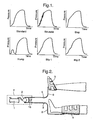
- FIG. 1 there are several waveform shapes that are generated, some examples illustrated in Figure 1 .
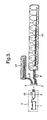
- a preferred embodiment of the invention applies the identification means to a compression garment and pump system as shown in Figure 2 .
- a compressor 1 forces air via a pressure control unit, for example a rotor and stator unit 2 to inflate the garments 3, 4 at the desired times and to the desired pressures appropriate to the therapy.
- the foot garment 3 is inflated to 130 mmHg for a short period of one second whilst the calf garments 4 (or thigh garment, not shown) are inflated to only 40 mmHg but the pressure is held for a longer period say, eight seconds.
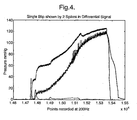
- the garments 3, 4 are each identified by very small steps generated in the waveform during inflation, the identification means in this example showing one step for the calf garment (see Figure 4 ) and two steps for the foot garment 3 (see Figure 5 ).
- Figure 6 shows the inflation of a foot garment without the identification means where only the initial spike of initiating inflation is seen without any of the differentiating steps thereafter.
- the identification means 9 creating the waveform steps can be located anywhere along the tubing and it may be advantageous to locate it at the end of the tubing where it joins to the garment or similar inflatable article as it will prevent non authorised use of the system.
- the identification means 9 is located within the connector in the preferred embodiment.
- the identification means consists of a main flat sheet valve 9 in the connector chamber 8 having several vents 10 to atmosphere and comprising the main flow path from the compressor 1 to the garment (s) 3, 4.
- the main flat sheet valve 9 has two sections 12 and 13 that are free to bend independently with a firmness dependent on the sheet material and the geometry of the valve. It also has a 'horseshoe' flap 11 that opens up under pressure allowing air flow into the garments 3, 4, as shown in Figure 8 .
- the air In use, upon initiation of inflation, the air travels into the.chamber 8 and then following the path of least resistance the air flows out of the vents 10 to atmosphere rather than into the garment(s) 3, 4.
- the sheet valve 9 that is open at a set mounting angle within the chamber 8 is forced shut by the air flowing around it.
- the horseshoe flap 11 is shut at this time so the air pushes the main valve 9 as if it were a single solid sheet.
- section 12 cuts off all the vents 10 to atmosphere, the pressure in the chamber 8 builds up and the horseshoe flap 11 opens allowing the garment 3, 4 to inflate as normal.
- the pump 7 initially inflates to detect either one or two steps, and depending on the number of steps detected, the pump provides the appropriate pre-set therapy. If the garments 3 or 4 are changed whilst the pump 7 is turned on it will detect the change in steps before complete inflation and change the therapies. If a standard connector is used then there are no steps detected apart from the initial spike as shown in Figure 6 and no therapy will be supplied by the pump. The steps are generated regardless of the length of tubing between the garments and the pump. The distance between the steps can be used to detect leaks or low pressure and therefore can be used as a feedback mechanism to set the correct inflation regime.
- the pump can be used to supply pressurised air to a support surface as shown in Figure 3 .
- the pump recognises the support surface by means of the steps detected during initial inflation.
- the pump will be pre-set to supply different inflation and deflation cycles and pressures as appropriate.
- the invention can be used where there is a requirement to automatically identify the article connected to a pump and apply the appropriate inflation regime with respect to the timings and pressure.
- the steps are generated before the article is inflated allowing the regime to be modified or stopped before the wrong therapy is applied.
- the geometry of the chamber, vents sizes, flap material and flap design all have an affect on the operation of the identifying means and the means can be tuned for any particular flow regime desired.
Landscapes
- Health & Medical Sciences (AREA)
- Life Sciences & Earth Sciences (AREA)
- Engineering & Computer Science (AREA)
- Surgery (AREA)
- General Health & Medical Sciences (AREA)
- Animal Behavior & Ethology (AREA)
- Nuclear Medicine, Radiotherapy & Molecular Imaging (AREA)
- Veterinary Medicine (AREA)
- Public Health (AREA)
- Biomedical Technology (AREA)
- Heart & Thoracic Surgery (AREA)
- Medical Informatics (AREA)
- Molecular Biology (AREA)
- Computer Hardware Design (AREA)
- Oral & Maxillofacial Surgery (AREA)
- Hematology (AREA)
- Reproductive Health (AREA)
- Vascular Medicine (AREA)
- Mechanical Engineering (AREA)
- General Engineering & Computer Science (AREA)
- Physics & Mathematics (AREA)
- Electromagnetism (AREA)
- Biophysics (AREA)
- Pathology (AREA)
- Massaging Devices (AREA)
- Orthopedics, Nursing, And Contraception (AREA)
- Control Of El Displays (AREA)
- Eye Examination Apparatus (AREA)
- Control Of Vending Devices And Auxiliary Devices For Vending Devices (AREA)
- Invalid Beds And Related Equipment (AREA)
Abstract
Description
- The present invention relates to a device supplying pressurised air to an inflatable article and in particular to means in such a device for identifying the article connected.
- Existing methods for identifying the article connected to a pump include RFIDs as well metal inserts located in the article connectors. The known methods are expensive and require additional connector parts to operate. It is also known to have identifying means in blood pressure measurement where a pressure waveforms is generated indicative of the cuff size being utilized (see
US500 3981 , closest prion art). - The invention seeks to make improvements.
- Accordingly, the invention provides a pump supplying pressurised air to an inflatable article and means for identifying the article connected by way of a pressure waveform generated as the article is initially inflated as claimed in
claim 1.
According to a preferred embodiment of the invention, the identification means is connected to a compression garment supplied with pressurised air from a pump. According to another preferred embodiment of the invention the identification means is connected to an inflatable support surface, such as a mattress or cushion. Preferably, pressure recordings taken from a pressure sensor in the pump identify the garment or inflatable support surface connected to the pump. Preferably, the identification means is located in the connector, such that as the air flows down the connection tubing and through the connector a pressure wave is mechanically generated and fed back upstream to the pressure sensor. As there are no wires in the system the technique will work with ordinary extension tubing. The identification means generates easily detectable pressure waveform shapes that are detected upstream by the pressure sensor in the pump and advantageously does not effect the inflation applied to the garment or similar article. - An example of the invention will now be described with reference to the accompanying drawings, in which:
-
Figure 1 shows a schematic representation of pressure waveforms generated by an identification means according to the invention; -
Figure 2 is a schematic representation of a preferred embodiment of the invention; -
Figure 3 is a schematic representation of another preferred embodiment of the invention; -
Figure 4 shows an identifying pressure wave according to the invention;, -
Figure 5 shows another identifying pressure wave according to the invention; -
Figure 6 shows a pressure wave of the prior art; -
Figure 7 shows the identification means according to the invention; -
Figure 8 shows a valve of the identification means; -
Figure 9 shows one connector according to the invention; and -
Figure 10 shows another connector according to the invention. - Referring to the Figures, there are several waveform shapes that are generated, some examples illustrated in
Figure 1 . A preferred embodiment of the invention applies the identification means to a compression garment and pump system as shown inFigure 2 . Acompressor 1 forces air via a pressure control unit, for example a rotor andstator unit 2 to inflate thegarments foot garment 3 is inflated to 130 mmHg for a short period of one second whilst the calf garments 4 (or thigh garment, not shown) are inflated to only 40 mmHg but the pressure is held for a longer period say, eight seconds. Thegarments Figure 4 ) and two steps for the foot garment 3 (seeFigure 5 ).Figure 6 shows the inflation of a foot garment without the identification means where only the initial spike of initiating inflation is seen without any of the differentiating steps thereafter. - The identification means 9 creating the waveform steps can be located anywhere along the tubing and it may be advantageous to locate it at the end of the tubing where it joins to the garment or similar inflatable article as it will prevent non authorised use of the system.
- As shown in
Figure 7 , the identification means 9 is located within the connector in the preferred embodiment. The identification means consists of a mainflat sheet valve 9 in theconnector chamber 8 havingseveral vents 10 to atmosphere and comprising the main flow path from thecompressor 1 to the garment (s) 3, 4. The mainflat sheet valve 9 has twosections flap 11 that opens up under pressure allowing air flow into thegarments Figure 8 . - In use, upon initiation of inflation, the air travels into the.
chamber 8 and then following the path of least resistance the air flows out of thevents 10 to atmosphere rather than into the garment(s) 3, 4. At the same time, thesheet valve 9 that is open at a set mounting angle within thechamber 8 is forced shut by the air flowing around it. Thehorseshoe flap 11 is shut at this time so the air pushes themain valve 9 as if it were a single solid sheet. In the one step connector (as shown inFigure 9 ) as themain valve 9 shuts,section 12 cuts off all thevents 10 to atmosphere, the pressure in thechamber 8 builds up and thehorseshoe flap 11 opens allowing thegarment - This results in a single step being produced in the waveform detected by the
pressure sensor 15 in thepump unit 7, as shown inFigure 4 . A very simple method to detect this step is to differentiate the signal and count the spikes, in this case two spikes for the one step. In the two step version not all thevents 10 to atmosphere are cut off bysection 12, it is only after the next stage whensection 13 is forced down that all thevents 10 to atmosphere are cut off and thehorseshoe flap 11 opens. This results in two steps in the waveforms and three spikes counted in the differential signal, as seen inFigure 5 . - The
pump 7 initially inflates to detect either one or two steps, and depending on the number of steps detected, the pump provides the appropriate pre-set therapy. If thegarments pump 7 is turned on it will detect the change in steps before complete inflation and change the therapies. If a standard connector is used then there are no steps detected apart from the initial spike as shown inFigure 6 and no therapy will be supplied by the pump. The steps are generated regardless of the length of tubing between the garments and the pump. The distance between the steps can be used to detect leaks or low pressure and therefore can be used as a feedback mechanism to set the correct inflation regime. - Instead of the
compression garments Figure 3 . The same procedure applies and the pump recognises the support surface by means of the steps detected during initial inflation. With respect to the mattresses and cushions, the pump will be pre-set to supply different inflation and deflation cycles and pressures as appropriate. Similarly, the invention can be used where there is a requirement to automatically identify the article connected to a pump and apply the appropriate inflation regime with respect to the timings and pressure. - The steps are generated before the article is inflated allowing the regime to be modified or stopped before the wrong therapy is applied.
- The geometry of the chamber, vents sizes, flap material and flap design all have an affect on the operation of the identifying means and the means can be tuned for any particular flow regime desired.
Claims (7)
- A pump (7) for supplying pressurised air to an inflatable article the pump comprising a connection tubing and a connector to the inflatable particle, means for identifying the article (9), the identifying means (9) generating a pressure waveform as the air flows through the connection tubing and connector as the article is initially inflated, the pressure waveform detected by a pressure seneor (15) in the pump and control means identifying the waveform to a particular article characterised in that the identifying means is a flat sheet valve, the valve interrupting the air flow to generate a pressure waveform detectable by the pressure sensor (15), the pressure waveform serving to identify the inflatable article.
- A pump as claimed in claim 1 characterised in that the valve includes a vent (10) to the atmosphere, wherein the vent is closed after a delay following the start of the inflation of the article.
- A pump as claimed in claim 1 characterised in that the valve includes two or more vents (10) to the atmosphere, wherein at least some of the vents (10) are closed in succession during the course of inflation of the article.
- A pump as claimed in any preceding claim characterised in that the identifying means is located in the connector connecting the article to the pump.
- A pump as claimed any preceding claim characterised in that the identifying means is located in the tubing connecting the article to the pump.
- A pump as claimed in any preceding claim characterised in that the article is an inflatable support surface.
- A pump as claimed in any preceding claim characterised in that the article is compression garment.
Applications Claiming Priority (2)
| Application Number | Priority Date | Filing Date | Title |
|---|---|---|---|
| GBGB0523249.1A GB0523249D0 (en) | 2005-11-15 | 2005-11-15 | Identification means |
| PCT/GB2006/004154 WO2007057639A1 (en) | 2005-11-15 | 2006-11-07 | Identification means |
Publications (2)
| Publication Number | Publication Date |
|---|---|
| EP1948013A1 EP1948013A1 (en) | 2008-07-30 |
| EP1948013B1 true EP1948013B1 (en) | 2011-10-19 |
Family
ID=35516955
Family Applications (1)
| Application Number | Title | Priority Date | Filing Date |
|---|---|---|---|
| EP06808449A Not-in-force EP1948013B1 (en) | 2005-11-15 | 2006-11-07 | Identification means |
Country Status (9)
| Country | Link |
|---|---|
| US (1) | US8235922B2 (en) |
| EP (1) | EP1948013B1 (en) |
| JP (1) | JP4896984B2 (en) |
| CN (1) | CN101309635A (en) |
| AT (1) | ATE529040T1 (en) |
| AU (1) | AU2006314267A1 (en) |
| CA (1) | CA2637328A1 (en) |
| GB (1) | GB0523249D0 (en) |
| WO (1) | WO2007057639A1 (en) |
Families Citing this family (29)
| Publication number | Priority date | Publication date | Assignee | Title |
|---|---|---|---|---|
| US9642759B2 (en) | 2007-04-13 | 2017-05-09 | Stryker Corporation | Patient support with universal energy supply system |
| DE102012110827A1 (en) * | 2012-11-12 | 2014-05-15 | Ulrich Gmbh & Co. Kg | Control device and control system for a tourniquet device |
| USD737328S1 (en) | 2013-06-17 | 2015-08-25 | Covidien Lp | Display screen with graphical user interface for venous refill detection |
| USD737327S1 (en) | 2013-06-17 | 2015-08-25 | Covidien Lp | Display screen with a transitional leak detection icon |
| USD760728S1 (en) | 2013-06-17 | 2016-07-05 | Covidien Lp | Display screen with graphical user interface for patient use meter reset |
| USD774057S1 (en) | 2013-06-17 | 2016-12-13 | Covidien Lp | Display screen with a graphical user interface for compliance monitoring |
| USD737855S1 (en) | 2013-06-17 | 2015-09-01 | Covidien Lp | Display screen with a transitional venous refill detection icon |
| US10071011B2 (en) | 2014-06-30 | 2018-09-11 | Kpr U.S., Llc | Compression garment inflation |
| US10667984B2 (en) | 2015-12-18 | 2020-06-02 | Stryker Corporation | Systems and methods for operating patient therapy devices |
| US11410771B2 (en) | 2017-06-01 | 2022-08-09 | Stryker Corporation | Patient care devices with open communication |
| US11173085B2 (en) | 2017-12-28 | 2021-11-16 | Stryker Corporation | Mattress cover for a mattress providing rotation therapy to a patient |
| US11246775B2 (en) | 2017-12-28 | 2022-02-15 | Stryker Corporation | Patient turning device for a patient support apparatus |
| USD877915S1 (en) | 2018-09-28 | 2020-03-10 | Stryker Corporation | Crib assembly |
| USD879966S1 (en) | 2018-09-28 | 2020-03-31 | Stryker Corporation | Crib assembly |
| USD888962S1 (en) | 2018-09-28 | 2020-06-30 | Stryker Corporation | Cover assembly for a patient support |
| USD888963S1 (en) | 2018-09-28 | 2020-06-30 | Stryker Corporation | Cover assembly for a patient support |
| USD888964S1 (en) | 2018-09-28 | 2020-06-30 | Stryker Corporation | Crib assembly for a patient support |
| USD977109S1 (en) | 2018-09-28 | 2023-01-31 | Stryker Corporation | Crib assembly for a patient support |
| US11219567B2 (en) | 2018-09-28 | 2022-01-11 | Stryker Corporation | Patient support |
| USD894956S1 (en) | 2018-10-31 | 2020-09-01 | Stryker Corporation | Display screen or portion thereof with graphical user interface |
| USD894226S1 (en) | 2018-10-31 | 2020-08-25 | Stryker Corporation | Display screen or portion thereof with graphical user interface |
| USD892159S1 (en) | 2018-10-31 | 2020-08-04 | Stryker Corporation | Display screen with animated graphical user interface |
| USD894957S1 (en) | 2018-10-31 | 2020-09-01 | Stryker Corporation | Display screen or portion thereof with graphical user interface |
| USD893543S1 (en) | 2018-10-31 | 2020-08-18 | Stryker Corporation | Display screen with graphical user interface |
| USD890914S1 (en) | 2018-10-31 | 2020-07-21 | Stryker Corporation | Pump |
| USD894223S1 (en) | 2018-10-31 | 2020-08-25 | Stryker Corporation | Display screen with animated graphical user interface |
| US12171533B2 (en) * | 2020-02-17 | 2024-12-24 | Zimmer, Inc. | Automatic cuff identification system and method |
| WO2022132013A1 (en) | 2020-12-18 | 2022-06-23 | Arjo IP Holding Aktiebolag | Fluid pressure control system, connector and coupling assembly |
| US12508191B2 (en) | 2021-10-13 | 2025-12-30 | Hill-Rom Services Pte. Ltd. | High frequency chest wall oscillation air pulse generator having pressure sensor for feedback control |
Family Cites Families (10)
| Publication number | Priority date | Publication date | Assignee | Title |
|---|---|---|---|---|
| US4501280A (en) * | 1983-04-06 | 1985-02-26 | Critikon, Inc. | Automatic identification of cuff size in automated blood pressure monitors |
| JPS6211431A (en) * | 1985-07-08 | 1987-01-20 | コーリン電子株式会社 | Method and apparatus for discriminating kind of cuff |
| FI80199C (en) * | 1988-07-08 | 1990-05-10 | Instrumentarium Oy | FOERFARANDE FOER INDIKERING AV MANSCHETTSTORLEKEN I EN BLODTRYCKSMAETARE OCH ETT VID INDIKERINGEN BEHOEVLIGT, STROEMNINGEN BEGRAENSANDE ORGAN. |
| FI84691C (en) * | 1989-03-17 | 1992-01-10 | Instrumentarium Oy | FOERFARANDE FOER IDENTIFIERING AV EN BLODTRYCKSMAETARES MANSETTYP. |
| JPH0667381B2 (en) * | 1989-05-24 | 1994-08-31 | テルモ株式会社 | Electronic blood pressure monitor |
| FI86504C (en) * | 1990-12-18 | 1992-09-10 | Instrumentarium Oy | FOERFARANDE FOER IDENTIFIERING AV EN NONINVASIV TRYCKMAETARES MANSCHETTTYP. |
| US5600654A (en) * | 1993-07-29 | 1997-02-04 | Lucent Technologies Inc. | Multiple call offering method for use with an analog station and an ISDN station that share a directory number |
| FI20012174L (en) * | 2001-11-09 | 2003-05-10 | Instrumentarium Oyj | Method and arrangement for identifying a measuring cuff |
| JP4602996B2 (en) * | 2004-02-23 | 2010-12-22 | タイコ・ヘルスケアー・グループ・エルピー | Fluid conduit connector device |
| JP2005261820A (en) * | 2004-03-22 | 2005-09-29 | Fukuda Denshi Co Ltd | Cuff type discrimination method and non-invasive blood pressure measuring device |
-
2005
- 2005-11-15 GB GBGB0523249.1A patent/GB0523249D0/en not_active Ceased
-
2006
- 2006-11-07 CN CNA2006800425876A patent/CN101309635A/en active Pending
- 2006-11-07 EP EP06808449A patent/EP1948013B1/en not_active Not-in-force
- 2006-11-07 JP JP2008540674A patent/JP4896984B2/en not_active Expired - Fee Related
- 2006-11-07 AU AU2006314267A patent/AU2006314267A1/en not_active Abandoned
- 2006-11-07 WO PCT/GB2006/004154 patent/WO2007057639A1/en not_active Ceased
- 2006-11-07 AT AT06808449T patent/ATE529040T1/en not_active IP Right Cessation
- 2006-11-07 US US12/093,724 patent/US8235922B2/en not_active Expired - Fee Related
- 2006-11-07 CA CA002637328A patent/CA2637328A1/en not_active Abandoned
Also Published As
| Publication number | Publication date |
|---|---|
| CA2637328A1 (en) | 2007-05-24 |
| ATE529040T1 (en) | 2011-11-15 |
| EP1948013A1 (en) | 2008-07-30 |
| JP2009515627A (en) | 2009-04-16 |
| GB0523249D0 (en) | 2005-12-21 |
| US20080281241A1 (en) | 2008-11-13 |
| WO2007057639A1 (en) | 2007-05-24 |
| AU2006314267A1 (en) | 2007-05-24 |
| US8235922B2 (en) | 2012-08-07 |
| JP4896984B2 (en) | 2012-03-14 |
| CN101309635A (en) | 2008-11-19 |
Similar Documents
| Publication | Publication Date | Title |
|---|---|---|
| US8235922B2 (en) | Identification means | |
| SG143164A1 (en) | Inflatable bed having a built-in electric air pump unit for inflating a mattress assembly | |
| WO2001068354A3 (en) | Inflator/sealer device for inflatable packaging cushion | |
| DE69504144D1 (en) | Device for inflating an inflatable restraint system | |
| KR102596382B1 (en) | compression garment conformability | |
| CN114668645B (en) | Air pressure massager and control method thereof | |
| EP1839963A3 (en) | An airbag for a motor vehicle | |
| CN104768456B (en) | Control device and control system for hemostat device | |
| WO2007002154A3 (en) | Medical fluid injection and inflation system | |
| DE69506202D1 (en) | Airbag flow regulating valve | |
| WO2009156817A8 (en) | Kit, with an improved gauge, for repairing and inflating inflatable articles, and relative method | |
| WO2007045646A3 (en) | Bleed air supply system and method to supply bleed air to an aircraft | |
| EP1447070A1 (en) | Seat with massaging apparatus and process for performing a massage | |
| WO2009013932A1 (en) | Airbag and airbag device | |
| AU5870098A (en) | Method and apparatus for quick inflating of an inflatable bag, particularly a supporting device bag, such as mattress | |
| CN206749596U (en) | A kind of automotive seat regulating system and automobile | |
| US10253893B2 (en) | Inflation valve seat with adjustable flow | |
| GB0225118D0 (en) | Providing an indication of the position of a valve member | |
| US20160331245A1 (en) | Semi-automatic sphygmomanometer system | |
| EP1072489A3 (en) | Inflation of tires with deoxygenated air | |
| AU2001266141A1 (en) | Leakage detection method for a pressurised medical appliance | |
| AU2006266569A8 (en) | Continuous positive airway pressure device | |
| WO2003022632A3 (en) | Vehicle restraint system | |
| TW200922542A (en) | Air bag massage device and method and program for controlling the same | |
| US20150088009A1 (en) | Semi-automatic sphygmomanometer system |
Legal Events
| Date | Code | Title | Description |
|---|---|---|---|
| PUAI | Public reference made under article 153(3) epc to a published international application that has entered the european phase |
Free format text: ORIGINAL CODE: 0009012 |
|
| 17P | Request for examination filed |
Effective date: 20080430 |
|
| AK | Designated contracting states |
Kind code of ref document: A1 Designated state(s): AT BE BG CH CY CZ DE DK EE ES FI FR GB GR HU IE IS IT LI LT LU LV MC NL PL PT RO SE SI SK TR |
|
| 17Q | First examination report despatched |
Effective date: 20090713 |
|
| GRAP | Despatch of communication of intention to grant a patent |
Free format text: ORIGINAL CODE: EPIDOSNIGR1 |
|
| DAX | Request for extension of the european patent (deleted) | ||
| GRAS | Grant fee paid |
Free format text: ORIGINAL CODE: EPIDOSNIGR3 |
|
| GRAA | (expected) grant |
Free format text: ORIGINAL CODE: 0009210 |
|
| AK | Designated contracting states |
Kind code of ref document: B1 Designated state(s): AT BE BG CH CY CZ DE DK EE ES FI FR GB GR HU IE IS IT LI LT LU LV MC NL PL PT RO SE SI SK TR |
|
| REG | Reference to a national code |
Ref country code: GB Ref legal event code: FG4D |
|
| REG | Reference to a national code |
Ref country code: CH Ref legal event code: EP |
|
| REG | Reference to a national code |
Ref country code: IE Ref legal event code: FG4D |
|
| REG | Reference to a national code |
Ref country code: DE Ref legal event code: R096 Ref document number: 602006025312 Country of ref document: DE Effective date: 20111222 |
|
| REG | Reference to a national code |
Ref country code: NL Ref legal event code: VDEP Effective date: 20111019 |
|
| LTIE | Lt: invalidation of european patent or patent extension |
Effective date: 20111019 |
|
| REG | Reference to a national code |
Ref country code: AT Ref legal event code: MK05 Ref document number: 529040 Country of ref document: AT Kind code of ref document: T Effective date: 20111019 |
|
| PG25 | Lapsed in a contracting state [announced via postgrant information from national office to epo] |
Ref country code: IS Free format text: LAPSE BECAUSE OF FAILURE TO SUBMIT A TRANSLATION OF THE DESCRIPTION OR TO PAY THE FEE WITHIN THE PRESCRIBED TIME-LIMIT Effective date: 20120219 Ref country code: BE Free format text: LAPSE BECAUSE OF FAILURE TO SUBMIT A TRANSLATION OF THE DESCRIPTION OR TO PAY THE FEE WITHIN THE PRESCRIBED TIME-LIMIT Effective date: 20111019 Ref country code: LT Free format text: LAPSE BECAUSE OF FAILURE TO SUBMIT A TRANSLATION OF THE DESCRIPTION OR TO PAY THE FEE WITHIN THE PRESCRIBED TIME-LIMIT Effective date: 20111019 |
|
| PG25 | Lapsed in a contracting state [announced via postgrant information from national office to epo] |
Ref country code: NL Free format text: LAPSE BECAUSE OF FAILURE TO SUBMIT A TRANSLATION OF THE DESCRIPTION OR TO PAY THE FEE WITHIN THE PRESCRIBED TIME-LIMIT Effective date: 20111019 Ref country code: GR Free format text: LAPSE BECAUSE OF FAILURE TO SUBMIT A TRANSLATION OF THE DESCRIPTION OR TO PAY THE FEE WITHIN THE PRESCRIBED TIME-LIMIT Effective date: 20120120 Ref country code: LV Free format text: LAPSE BECAUSE OF FAILURE TO SUBMIT A TRANSLATION OF THE DESCRIPTION OR TO PAY THE FEE WITHIN THE PRESCRIBED TIME-LIMIT Effective date: 20111019 Ref country code: SI Free format text: LAPSE BECAUSE OF FAILURE TO SUBMIT A TRANSLATION OF THE DESCRIPTION OR TO PAY THE FEE WITHIN THE PRESCRIBED TIME-LIMIT Effective date: 20111019 Ref country code: PT Free format text: LAPSE BECAUSE OF FAILURE TO SUBMIT A TRANSLATION OF THE DESCRIPTION OR TO PAY THE FEE WITHIN THE PRESCRIBED TIME-LIMIT Effective date: 20120220 Ref country code: SE Free format text: LAPSE BECAUSE OF FAILURE TO SUBMIT A TRANSLATION OF THE DESCRIPTION OR TO PAY THE FEE WITHIN THE PRESCRIBED TIME-LIMIT Effective date: 20111019 |
|
| PG25 | Lapsed in a contracting state [announced via postgrant information from national office to epo] |
Ref country code: CY Free format text: LAPSE BECAUSE OF FAILURE TO SUBMIT A TRANSLATION OF THE DESCRIPTION OR TO PAY THE FEE WITHIN THE PRESCRIBED TIME-LIMIT Effective date: 20111019 Ref country code: MC Free format text: LAPSE BECAUSE OF NON-PAYMENT OF DUE FEES Effective date: 20111130 |
|
| REG | Reference to a national code |
Ref country code: CH Ref legal event code: PL |
|
| PG25 | Lapsed in a contracting state [announced via postgrant information from national office to epo] |
Ref country code: BG Free format text: LAPSE BECAUSE OF FAILURE TO SUBMIT A TRANSLATION OF THE DESCRIPTION OR TO PAY THE FEE WITHIN THE PRESCRIBED TIME-LIMIT Effective date: 20120119 Ref country code: LI Free format text: LAPSE BECAUSE OF NON-PAYMENT OF DUE FEES Effective date: 20111130 Ref country code: SK Free format text: LAPSE BECAUSE OF FAILURE TO SUBMIT A TRANSLATION OF THE DESCRIPTION OR TO PAY THE FEE WITHIN THE PRESCRIBED TIME-LIMIT Effective date: 20111019 Ref country code: CZ Free format text: LAPSE BECAUSE OF FAILURE TO SUBMIT A TRANSLATION OF THE DESCRIPTION OR TO PAY THE FEE WITHIN THE PRESCRIBED TIME-LIMIT Effective date: 20111019 Ref country code: EE Free format text: LAPSE BECAUSE OF FAILURE TO SUBMIT A TRANSLATION OF THE DESCRIPTION OR TO PAY THE FEE WITHIN THE PRESCRIBED TIME-LIMIT Effective date: 20111019 Ref country code: DK Free format text: LAPSE BECAUSE OF FAILURE TO SUBMIT A TRANSLATION OF THE DESCRIPTION OR TO PAY THE FEE WITHIN THE PRESCRIBED TIME-LIMIT Effective date: 20111019 Ref country code: CH Free format text: LAPSE BECAUSE OF NON-PAYMENT OF DUE FEES Effective date: 20111130 |
|
| PLBE | No opposition filed within time limit |
Free format text: ORIGINAL CODE: 0009261 |
|
| STAA | Information on the status of an ep patent application or granted ep patent |
Free format text: STATUS: NO OPPOSITION FILED WITHIN TIME LIMIT |
|
| REG | Reference to a national code |
Ref country code: IE Ref legal event code: MM4A |
|
| PG25 | Lapsed in a contracting state [announced via postgrant information from national office to epo] |
Ref country code: PL Free format text: LAPSE BECAUSE OF FAILURE TO SUBMIT A TRANSLATION OF THE DESCRIPTION OR TO PAY THE FEE WITHIN THE PRESCRIBED TIME-LIMIT Effective date: 20111019 Ref country code: RO Free format text: LAPSE BECAUSE OF FAILURE TO SUBMIT A TRANSLATION OF THE DESCRIPTION OR TO PAY THE FEE WITHIN THE PRESCRIBED TIME-LIMIT Effective date: 20111019 Ref country code: IT Free format text: LAPSE BECAUSE OF FAILURE TO SUBMIT A TRANSLATION OF THE DESCRIPTION OR TO PAY THE FEE WITHIN THE PRESCRIBED TIME-LIMIT Effective date: 20111019 |
|
| REG | Reference to a national code |
Ref country code: DE Ref legal event code: R119 Ref document number: 602006025312 Country of ref document: DE Effective date: 20120601 |
|
| REG | Reference to a national code |
Ref country code: FR Ref legal event code: ST Effective date: 20120817 |
|
| 26N | No opposition filed |
Effective date: 20120720 |
|
| GBPC | Gb: european patent ceased through non-payment of renewal fee |
Effective date: 20120119 |
|
| PG25 | Lapsed in a contracting state [announced via postgrant information from national office to epo] |
Ref country code: GB Free format text: LAPSE BECAUSE OF NON-PAYMENT OF DUE FEES Effective date: 20120119 Ref country code: IE Free format text: LAPSE BECAUSE OF NON-PAYMENT OF DUE FEES Effective date: 20111107 |
|
| PG25 | Lapsed in a contracting state [announced via postgrant information from national office to epo] |
Ref country code: AT Free format text: LAPSE BECAUSE OF FAILURE TO SUBMIT A TRANSLATION OF THE DESCRIPTION OR TO PAY THE FEE WITHIN THE PRESCRIBED TIME-LIMIT Effective date: 20111019 |
|
| PG25 | Lapsed in a contracting state [announced via postgrant information from national office to epo] |
Ref country code: FR Free format text: LAPSE BECAUSE OF NON-PAYMENT OF DUE FEES Effective date: 20111219 Ref country code: ES Free format text: LAPSE BECAUSE OF FAILURE TO SUBMIT A TRANSLATION OF THE DESCRIPTION OR TO PAY THE FEE WITHIN THE PRESCRIBED TIME-LIMIT Effective date: 20120130 |
|
| PG25 | Lapsed in a contracting state [announced via postgrant information from national office to epo] |
Ref country code: LU Free format text: LAPSE BECAUSE OF NON-PAYMENT OF DUE FEES Effective date: 20111107 |
|
| PG25 | Lapsed in a contracting state [announced via postgrant information from national office to epo] |
Ref country code: FI Free format text: LAPSE BECAUSE OF FAILURE TO SUBMIT A TRANSLATION OF THE DESCRIPTION OR TO PAY THE FEE WITHIN THE PRESCRIBED TIME-LIMIT Effective date: 20111019 Ref country code: DE Free format text: LAPSE BECAUSE OF NON-PAYMENT OF DUE FEES Effective date: 20120601 |
|
| PG25 | Lapsed in a contracting state [announced via postgrant information from national office to epo] |
Ref country code: TR Free format text: LAPSE BECAUSE OF FAILURE TO SUBMIT A TRANSLATION OF THE DESCRIPTION OR TO PAY THE FEE WITHIN THE PRESCRIBED TIME-LIMIT Effective date: 20111019 |
|
| PG25 | Lapsed in a contracting state [announced via postgrant information from national office to epo] |
Ref country code: HU Free format text: LAPSE BECAUSE OF FAILURE TO SUBMIT A TRANSLATION OF THE DESCRIPTION OR TO PAY THE FEE WITHIN THE PRESCRIBED TIME-LIMIT Effective date: 20111019 |