EP1947787A1 - An optical communication system for wireless radio signals - Google Patents
An optical communication system for wireless radio signals Download PDFInfo
- Publication number
- EP1947787A1 EP1947787A1 EP08103760A EP08103760A EP1947787A1 EP 1947787 A1 EP1947787 A1 EP 1947787A1 EP 08103760 A EP08103760 A EP 08103760A EP 08103760 A EP08103760 A EP 08103760A EP 1947787 A1 EP1947787 A1 EP 1947787A1
- Authority
- EP
- European Patent Office
- Prior art keywords
- fibre
- launch
- multimode
- multimode fibre
- modes
- Prior art date
- Legal status (The legal status is an assumption and is not a legal conclusion. Google has not performed a legal analysis and makes no representation as to the accuracy of the status listed.)
- Withdrawn
Links
- 230000003287 optical effect Effects 0.000 title claims abstract description 24
- 238000004891 communication Methods 0.000 title description 9
- 239000000835 fiber Substances 0.000 claims abstract description 87
- 230000005540 biological transmission Effects 0.000 claims abstract description 18
- 238000000034 method Methods 0.000 claims abstract description 6
- 230000003750 conditioning effect Effects 0.000 claims 1
- 230000005855 radiation Effects 0.000 abstract description 9
- 239000006185 dispersion Substances 0.000 abstract description 5
- 238000009499 grossing Methods 0.000 abstract description 2
- 238000011084 recovery Methods 0.000 abstract 1
- 238000013459 approach Methods 0.000 description 4
- 238000005259 measurement Methods 0.000 description 4
- 230000008878 coupling Effects 0.000 description 3
- 238000010168 coupling process Methods 0.000 description 3
- 238000005859 coupling reaction Methods 0.000 description 3
- 230000000694 effects Effects 0.000 description 3
- 238000002474 experimental method Methods 0.000 description 3
- 238000009434 installation Methods 0.000 description 3
- 238000012544 monitoring process Methods 0.000 description 3
- 230000008054 signal transmission Effects 0.000 description 3
- 238000012360 testing method Methods 0.000 description 3
- VYPSYNLAJGMNEJ-UHFFFAOYSA-N Silicium dioxide Chemical compound O=[Si]=O VYPSYNLAJGMNEJ-UHFFFAOYSA-N 0.000 description 2
- 238000013461 design Methods 0.000 description 2
- 230000003321 amplification Effects 0.000 description 1
- 230000015556 catabolic process Effects 0.000 description 1
- 230000001413 cellular effect Effects 0.000 description 1
- 238000006243 chemical reaction Methods 0.000 description 1
- 238000006731 degradation reaction Methods 0.000 description 1
- 230000006866 deterioration Effects 0.000 description 1
- 230000002708 enhancing effect Effects 0.000 description 1
- 238000011156 evaluation Methods 0.000 description 1
- 238000003780 insertion Methods 0.000 description 1
- 230000037431 insertion Effects 0.000 description 1
- 238000003199 nucleic acid amplification method Methods 0.000 description 1
- 239000013307 optical fiber Substances 0.000 description 1
- 239000000377 silicon dioxide Substances 0.000 description 1
- 230000003019 stabilising effect Effects 0.000 description 1
Images


Classifications
-
- H—ELECTRICITY
- H04—ELECTRIC COMMUNICATION TECHNIQUE
- H04B—TRANSMISSION
- H04B10/00—Transmission systems employing electromagnetic waves other than radio-waves, e.g. infrared, visible or ultraviolet light, or employing corpuscular radiation, e.g. quantum communication
- H04B10/25—Arrangements specific to fibre transmission
- H04B10/2575—Radio-over-fibre, e.g. radio frequency signal modulated onto an optical carrier
-
- H—ELECTRICITY
- H04—ELECTRIC COMMUNICATION TECHNIQUE
- H04B—TRANSMISSION
- H04B10/00—Transmission systems employing electromagnetic waves other than radio-waves, e.g. infrared, visible or ultraviolet light, or employing corpuscular radiation, e.g. quantum communication
- H04B10/25—Arrangements specific to fibre transmission
- H04B10/2575—Radio-over-fibre, e.g. radio frequency signal modulated onto an optical carrier
- H04B10/25752—Optical arrangements for wireless networks
-
- H—ELECTRICITY
- H04—ELECTRIC COMMUNICATION TECHNIQUE
- H04B—TRANSMISSION
- H04B10/00—Transmission systems employing electromagnetic waves other than radio-waves, e.g. infrared, visible or ultraviolet light, or employing corpuscular radiation, e.g. quantum communication
- H04B10/25—Arrangements specific to fibre transmission
- H04B10/2581—Multimode transmission
Definitions
- the invention relates to an optical communication system and in particular, to an optical communication system involving, multimode fibres installed in or connecting compartmented spaces such as corporate office, buildings, shopping centres, subways and airports.
- DAS distributed antenna system
- Analogue optical links using radio over fibre are in use today in many DAS installations around the world.
- these products either use single mode fibre (SMF) to provide the necessary transmission bandwidth or use multimode fibre (MMF) at a down converted intermediate frequency that is within the bandwidth of the multimode fibre.
- SMF single mode fibre
- MMF multimode fibre
- the drawbacks of these approaches are that the first requires specially installed fibre (as the majority of the installed fibre base within buildings is multimode) and the second requires the simultaneous transmission of a low frequency reference tone for stabilising and locking the remote local oscillators required for up-conversion back to the radio carrier. Both approaches result in additional cost and complexity to the transmission equipment and system design.
- Multimode fibre has a typical specified bandwidth of 500MHz.km at 1300nm wavelength. This specified bandwidth refers to the over-filled launch condition, where all the available modes in the fibre are excited.
- a current third generation mobile system operating around 2GHz would be limited to a DAS length of less than 250m. Lengths such as these have applications within small installations but the majority of DAS applications require substantially larger spans.
- multimode fibre may have many tens of modes, each travelling at slightly different speeds through the fibre. The phase differences between these modes apparent at the receiver results in interference, and this interference limits the fibre bandwidth. If the number and type of modes are restricted at launch, then modal dispersion can be greatly reduced and the fibre bandwidth can be extended. Where the modal dispersion still effectively limits the bandwidth, it is known that a significant passband response beyond the 3dB bandwidth exists that can be used for the successful transmission of subcarriers or radio signals.
- Centre launch where the optical power from the signal transmitter is coupled into the central (low order) fibre modes using standard connectors and uniters, works very well for many fibres. However a significant proportion of the installed fibre base has very poor performance when used with centre launch, caused by imperfections in the refractive index profile of the fibre core.
- offset launch where the optical power is coupled into the higher order modes away from the fibre centre, can be used for successful baseband digital transmission in virtually all multimode fibres. This can be achieved using laser sources rather than the more conventional LEDs used in datacommunications systems, as exemplified by the published PCT patent specification no. WO97/3330 entitled 'MULTIMODE COMMUNICATIONS SYSTEMS (HEWLETT PACKARD COMPANY).
- offset launch is used to guarantee the specified (over-filled launch) bandwidth by enhancing the performance of some fibres that would otherwise have low bandwidth using conventional launch conditions.
- the present invention goes beyond both of these examples of prior art; the aim is not to guarantee fibre bandwidth but to ensure that signal transmission over the fibre occurs in a stable operating regime (for both amplitude and phase) not necessarily restricted to the fibre baseband bandwidth.
- the Wake prior art only demonstrated that radio frequency signal transmission was possible for specific examples of 'good' fibre.
- the essence of the present invention is the realisation that stable and robust radio frequency signal transmission can be achieved for all types of graded-index multimode fibre using restricted-mode launch techniques. This would enable successful use of the pre-installed fibre base, typically multimode fibres, within buildings or other compartmented spaces for DAS application. One resulting benefit would be the lack of any basic need to pre-measure fibre performance or indeed to install fibre specifically for this application resulting in low cost DAS installations.
- SFDR spurious-free dynamic range
- Error vector magnitude is a useful measure of signal quality in transmission systems with digital modulation and is often more convenient to measure than bit error ratio. It is generally assumed that a link with good SFDR performance would have good error vector magnitude (EVM) performance. The results obtained from tests of the present invention disprove this, highlighting instead link outages resulting from uacceptably high EVM. These outages occur as a result of high levels of modal phase noise, which is not readily observable from steady-state measurements of SFDR or frequency response. This outage problem is apparent from detailed measurement of EVM and has not been described in the prior art.
- the invention represents a non-obvious advance over existing preconceptions in the field; with advantageous results flowing from its application.
- An optical communication system comprising:
- the preferred method of restricting the number of modes excited in the fibre is by means of coupling light into the fibre using a launch that is co-linear but at an offset to the fibre axis.
- the fibre has a core diameter of 62.5 ⁇ m and where the offset distance measured from the centre of the multimode fibre core to the centre of the optical radiation emitted from the transmitter is from approximately 10 ⁇ m to approximately 30 ⁇ m.
- Optimal offset distance from approximately 23 ⁇ m to approximately 30 ⁇ m.
- the preferred embodiment of the Optical Communications System 11. comprises a signal input means 12, an optical radiation source 13, temperature monitoring means 14, a lensed single mode fibre (SMF) 15, a fibre-to-fibre coupler 16, a power monitoring means 17, launching means 18, a multimode fibre 19, a photodetector 20, signal amplification means 21, signal analysing means 22, a current source 23 and a voltage source 24 when configured for testing and evaluation of a plurality of launch conditions and fibre responses.
- SMF single mode fibre
- the optical radiation source 13 is a single transverse mode laser.
- the laser 13 is an uncooled 1300nm distributed feedback (DFB) device designed for 10 Gigabit Ethernet applications.
- DFB distributed feedback
- Light from the laser 13 was coupled into a lensed single mode fibre 15 and the alignment was controlled using a 90/10 coupler 16 and monitored for power losses 17.
- a precision xyz-stage was used to control the launch conditions into various combinations of reels of 'worst-case' multimode fibre 19.
- the photodetector 20 is a photodiode.
- the photodiode 20 having a multimode fibre 19 input and an electrical preamplifier 21 output stage form the optical receiver converting the low intensity modulated light back into an electrical signal.
- the signal analysing means 21 has the ability to both generate and demodulate a 32-QAM signal at a centre frequency of 2GHz with a symbol rate of 2Ms/s.
- 32-QAM modulation was chosen to provide a good test of the link performance as it requires a signal-to-noise ratio of more than 25dB and is representative of wireless voice and data communication modulation systems.
- Figure 2 shows error vector magnitude (EVM) as a function of offset position.
- the laser 13 was operated at a bias current of 50mA and at a temperature of 25°C.
- the solid line in this plot shows the mean value of EVM calculated from repeated measurements over a time period of a few minutes.
- the mean value plus and minus one standard deviation (broken lines) showing variability in performance over time are also plotted.
- Figure 4 shows the EVM performance of the link as a function of the offset position with a laser temperature of 85°C.
- the link performance is even worse near the centre, whereas offset launch is still very effective between 15 and 30 ⁇ m offsets.
- the reason for the deterioration of performance at centre launch is thought to be due to the shift in operating wavelength with temperature (which changes the dispersion properties of the fibre) rather than a reduction in laser linearity.
- Figure 5 shows how EVM varies with six different fibres, each 300m long, for either centre launch (using standard FC/PC connectors) or offset launch (using an offset launch patchcord). These fibres were the same as used for the standardisation of the offset launch technique described in the Gigabit Ethernet standard, IEEE 802.3z, 1998. All six fibres had core diameters of 62.5 ⁇ m and bandwidths near the specified limit of 500MHz.km at 1300nm wavelength. From this figure it can be seen that offset launch produces a better and more consistent performance for all of the fibres used.
- the metrics for quality include, but are not restricted to:
- Types of graded-index multimode fibre that can be used include, but are not restricted to:
- the means of coupling include, but are not restricted to:
Landscapes
- Physics & Mathematics (AREA)
- Electromagnetism (AREA)
- Engineering & Computer Science (AREA)
- Computer Networks & Wireless Communication (AREA)
- Signal Processing (AREA)
- Optical Communication System (AREA)
- Optical Couplings Of Light Guides (AREA)
Abstract
Description
- The invention relates to an optical communication system and in particular, to an optical communication system involving, multimode fibres installed in or connecting compartmented spaces such as corporate office, buildings, shopping centres, subways and airports.
- In-building coverage is an important and growing market for network operators and building owners who wish to deploy cellular radio or wireless LAN systems within buildings. The most effective and efficient way of providing this coverage is to place the base station inside the building and use a distributed antenna system (DAS) to provide a relatively uniform signal strength. DASs can be constructed using coaxial cable, but for longer spans optical fibre is preferred because the insertion loss is virtually independent of link length, simplifying the system design and future extensions.
- Analogue optical links using radio over fibre are in use today in many DAS installations around the world. However, these products either use single mode fibre (SMF) to provide the necessary transmission bandwidth or use multimode fibre (MMF) at a down converted intermediate frequency that is within the bandwidth of the multimode fibre. The drawbacks of these approaches are that the first requires specially installed fibre (as the majority of the installed fibre base within buildings is multimode) and the second requires the simultaneous transmission of a low frequency reference tone for stabilising and locking the remote local oscillators required for up-conversion back to the radio carrier. Both approaches result in additional cost and complexity to the transmission equipment and system design.
- Multimode fibre has a typical specified bandwidth of 500MHz.km at 1300nm wavelength. This specified bandwidth refers to the over-filled launch condition, where all the available modes in the fibre are excited. By way of illustration, a current third generation mobile system operating around 2GHz would be limited to a DAS length of less than 250m. Lengths such as these have applications within small installations but the majority of DAS applications require substantially larger spans.
- The known bandwidth problems associated with multimode fibre are attributed to modal dispersion. Depending on the launch conditions, multimode fibre may have many tens of modes, each travelling at slightly different speeds through the fibre. The phase differences between these modes apparent at the receiver results in interference, and this interference limits the fibre bandwidth. If the number and type of modes are restricted at launch, then modal dispersion can be greatly reduced and the fibre bandwidth can be extended. Where the modal dispersion still effectively limits the bandwidth, it is known that a significant passband response beyond the 3dB bandwidth exists that can be used for the successful transmission of subcarriers or radio signals.
- Centre launch, where the optical power from the signal transmitter is coupled into the central (low order) fibre modes using standard connectors and uniters, works very well for many fibres. However a significant proportion of the installed fibre base has very poor performance when used with centre launch, caused by imperfections in the refractive index profile of the fibre core.
- It is known that offset launch, where the optical power is coupled into the higher order modes away from the fibre centre, can be used for successful baseband digital transmission in virtually all multimode fibres. This can be achieved using laser sources rather than the more conventional LEDs used in datacommunications systems, as exemplified by the published PCT patent specification no.
WO97/3330 - This, however, aims to guarantee bandwidth of multimode fibre for high data transmission rate digital baseband signal based systems (eg. Gigabit Ethernet).
- Furthermore, Wake et al showed recently (in Electronics Letters, vol.37, pp. 1087-1089, 2001) that it was possible to transmit radio frequency signals over multimode fibre by operating at frequencies in the flat-band region beyond the 3dB bandwidth of the fibre. This work opened up the possibility that a new type of radio over fibre transmission link was feasible, but stopped short from offering a stable and robust approach to the problem.
- The present invention goes beyond both of these examples of prior art; the aim is not to guarantee fibre bandwidth but to ensure that signal transmission over the fibre occurs in a stable operating regime (for both amplitude and phase) not necessarily restricted to the fibre baseband bandwidth. The Wake prior art only demonstrated that radio frequency signal transmission was possible for specific examples of 'good' fibre.
- The essence of the present invention is the realisation that stable and robust radio frequency signal transmission can be achieved for all types of graded-index multimode fibre using restricted-mode launch techniques. This would enable successful use of the pre-installed fibre base, typically multimode fibres, within buildings or other compartmented spaces for DAS application. One resulting benefit would be the lack of any basic need to pre-measure fibre performance or indeed to install fibre specifically for this application resulting in low cost DAS installations.
- This approach is a fundamental distinction over known existing digital communications systems using offset launch. They are limited to operating within the baseband bandwidth specification of the fibre. They do not suggest, in themselves, any appropriate starting point for the present invention. Nor can they achieve what the invention sets out to achieve.
- In addition, most prior art in the field of radio transmission over multimode fibre links has concentrated on spurious-free dynamic range (SFDR) as the major metric of performance. SFDR is defined as the maximum signal to noise ratio that the link can provide for the case where intermodulation distortion power is below the noise floor. SFDR incorporates elements of signal, noise and intermodulation distortion power.
- Error vector magnitude (EVM) is a useful measure of signal quality in transmission systems with digital modulation and is often more convenient to measure than bit error ratio. It is generally assumed that a link with good SFDR performance would have good error vector magnitude (EVM) performance. The results obtained from tests of the present invention disprove this, highlighting instead link outages resulting from uacceptably high EVM. These outages occur as a result of high levels of modal phase noise, which is not readily observable from steady-state measurements of SFDR or frequency response. This outage problem is apparent from detailed measurement of EVM and has not been described in the prior art.
- Here again, therefore, the invention represents a non-obvious advance over existing preconceptions in the field; with advantageous results flowing from its application.
- An optical communication system comprising:
- one or more optical radiation transmitters;
- a means of coupling optical radiation from the, or each, optical radiation transmitter into a multimode fibre using a launch which restricts the number of modes excited in the fibre and
- a photodetector;
- The preferred method of restricting the number of modes excited in the fibre is by means of coupling light into the fibre using a launch that is co-linear but at an offset to the fibre axis.
- Preferably in such an optical communication system where the fibre has a core diameter of 62.5µm and where the offset distance measured from the centre of the multimode fibre core to the centre of the optical radiation emitted from the transmitter is from approximately 10 µm to approximately 30 µm.
- Especially preferred is an optimum offset distance from approximately 23 µm to approximately 30 µm.
- Other features of the invention will become apparent from the description which follows.
- The present invention will now be described more particularly with reference to the accompanying drawings which show, by way of example only, a preferred embodiment of the optical communication system according to the invention.
- In the drawings:
-
Figure 1 presents an experimental configuration for demonstrating the preferred embodiment according to the invention. -
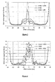
Figure 2 presents experimental results achieved with the experimental configuration ofFigure 1 comparing EVM and offset position over a short link low performance fibre. -
Figure 3 presents experimental results achieved with the experimental configuration ofFigure 1 performing the experiment as inFigure 2 but additionally varying offset in the z direction, defined as the distance along the extension of the fibre axis towards the optical radiation transmitter. -
Figure 4 presents experimental results achieved with the experimental configuration ofFigure 1 with a laser temperature of 85°C. -
Figure 5 presents experimental results comparing EVM in multiple multimode fibres when exited by an offset launch and by a centre launch. - Referring to the drawings and initially to
Figure 1 , the preferred embodiment of the Optical Communications System 11. according to the invention comprises a signal input means 12, an optical radiation source 13, temperature monitoring means 14, a lensed single mode fibre (SMF) 15, a fibre-to-fibre coupler 16, a power monitoring means 17, launching means 18, a multimode fibre 19, aphotodetector 20, signal amplification means 21, signal analysing means 22, a current source 23 and a voltage source 24 when configured for testing and evaluation of a plurality of launch conditions and fibre responses. - The effect of restricted launch on the transmission of high frequency radio signals over 'worst-case' multimode fibre using a complex digital modulation format (32-QAM) was measured in a series of experiments in order to determine the best strategy for ensuring good quality radio over fibre transmission over multimode fibre. In each case the offset launch gave better performance with less variability over time than centre launch indicating that offset launch in multimode fibre networks guarantees successful radio transmission without outages over 'worst-case' multimode fibre. Error vector magnitude (EVM) was used as the link performance metric in this series of measurements.
- The optical radiation source 13 is a single transverse mode laser. The laser 13 is an uncooled 1300nm distributed feedback (DFB) device designed for 10 Gigabit Ethernet applications.
- Light from the laser 13 was coupled into a lensed single mode fibre 15 and the alignment was controlled using a 90/10
coupler 16 and monitored for power losses 17. - A precision xyz-stage was used to control the launch conditions into various combinations of reels of 'worst-case' multimode fibre 19.
- Experimental results shown in
Figures 2 to 4 were achieved using 500m runs of 'worst-case' multimode fibre having a 62.5µm core diameter and a numerical aperture of 0.28. - The
photodetector 20 is a photodiode. Thephotodiode 20 having a multimode fibre 19 input and an electrical preamplifier 21 output stage form the optical receiver converting the low intensity modulated light back into an electrical signal. - The signal analysing means 21 has the ability to both generate and demodulate a 32-QAM signal at a centre frequency of 2GHz with a symbol rate of 2Ms/s. 32-QAM modulation was chosen to provide a good test of the link performance as it requires a signal-to-noise ratio of more than 25dB and is representative of wireless voice and data communication modulation systems.
-
Figure 2 shows error vector magnitude (EVM) as a function of offset position. The laser 13 was operated at a bias current of 50mA and at a temperature of 25°C. The solid line in this plot shows the mean value of EVM calculated from repeated measurements over a time period of a few minutes. The mean value plus and minus one standard deviation (broken lines) showing variability in performance over time are also plotted. - From
Figure 2 it can be seen that the most stable region of operation is at an offset position of between 10 and 30µm. In this region the EVM and the variability of EVM over time are both very low. There is also a very narrow region near the centre of the plot that has low EVM but it is surrounded by regions of unacceptable performance resulting in it not being possible to achieve acceptable performance for centre launch with any degree of repeatability using worst-case multimode fibre. - With reference to
Figure 3 , the previous experiment was repeated monitoring the effect of a small offset (3µm in the z direction). Good centre launch performance is even more difficult to obtain than previously, whereas the offset launch performance is just as good and as stable as before. -
Figure 4 shows the EVM performance of the link as a function of the offset position with a laser temperature of 85°C. The link performance is even worse near the centre, whereas offset launch is still very effective between 15 and 30µm offsets. The reason for the deterioration of performance at centre launch is thought to be due to the shift in operating wavelength with temperature (which changes the dispersion properties of the fibre) rather than a reduction in laser linearity. -
Figure 5 shows how EVM varies with six different fibres, each 300m long, for either centre launch (using standard FC/PC connectors) or offset launch (using an offset launch patchcord). These fibres were the same as used for the standardisation of the offset launch technique described in the Gigabit Ethernet standard, IEEE 802.3z, 1998. All six fibres had core diameters of 62.5µm and bandwidths near the specified limit of 500MHz.km at 1300nm wavelength. From this figure it can be seen that offset launch produces a better and more consistent performance for all of the fibres used. - When all six fibres were connected together giving a total link length of 1.8km the measured EVM was 6.1% with a standard deviation of 1.4% using a centre launch compared to an EVM of 1.6% with a standard deviation of less than 0.4% when the offset launch patchcord was used.
- Minimum EVM degradation correlates to smoothing of the RF transmission region beyond the 3dB bandwidth specification of the multimode fibre. As a result of this effect susceptibility of signal loss due to transmission nulls is substantially eliminated.
- The metrics for quality include, but are not restricted to:
- spurious free dynamic range (SFDR);
- error vector magnitude (EVM);
- and the variability of these parameters over time (to ensure that no outages occur).
- Types of graded-index multimode fibre that can be used include, but are not restricted to:
- old fibre that has been installed within buildings;
- new fibre;
- silica fibre;
- plastic fibre;
- fibre with multiples splices and/or connectors;
- fibre with low specified bandwidth; and
- fibre with high specified bandwidth.
- The means of coupling include, but are not restricted to:
- a launch from a single transverse mode laser with a single mode fibre pigtail into a gxaded-index multimode fibre using a mode-conditioning patchcord;
- a launch from a laser receptacle package into a graded-index multimode fibre where the axis of the optical output from a single transverse mode laser has been offset from that of the fibre.
- The scope of the invention is defined by the claims which now follow.
Claims (6)
- A distributed antenna system comprising an analogue optical link formed by a length of multimode fibre having imperfections in the refractive index profile of the fibre core, a laser diode, a photodiode for detecting light from the fibre and a launch for launching light from the laser diode into the multimode fibre to provide a restricted number of modes selected to provide a stable operating regime in the fibre
- A system according to claim 1, wherein the modes are selected to allow transmission in a region beyond the 3dB bandwidth specification of the multimode fibre
- A system according to claim 1 or 2, wherein the selected modes are higher order modes, without the low order modes achieved by central launch.
- A system according to claim 1 2 or 3, wherein the light is launched at an offset from the fibre centre.
- A system according to any preceding claim wherein the launch is one of a launch from a single transverse mode laser with a single mode fibre pigtail into a graded-index multimode fibre using a mode- conditioning patchcord, and a launch from a laser receptacle package into a graded-index multimode fibre where the axis of the optical output from a single transverse mode laser has been offset from that of the fibre.
- A method of operating a distributed antenna system having an analogue optical link formed by a length of multimode fibre having imperfections in the refractive index profile of the fibre core, a laser diode, and a photodiode for detecting light from the fibre; characterized by launching light from the laser diode into the multimode fibre to provide a restricted number of modes selected to provide a stable operating regime in the fibre.
Applications Claiming Priority (2)
| Application Number | Priority Date | Filing Date | Title |
|---|---|---|---|
| GBGB0229238.1A GB0229238D0 (en) | 2002-12-13 | 2002-12-13 | An optical communication system |
| EP03767990A EP1576746B8 (en) | 2002-12-13 | 2003-12-12 | An optical communication system for wireless radio signals |
Related Parent Applications (1)
| Application Number | Title | Priority Date | Filing Date |
|---|---|---|---|
| EP03767990A Division EP1576746B8 (en) | 2002-12-13 | 2003-12-12 | An optical communication system for wireless radio signals |
Publications (1)
| Publication Number | Publication Date |
|---|---|
| EP1947787A1 true EP1947787A1 (en) | 2008-07-23 |
Family
ID=9949734
Family Applications (2)
| Application Number | Title | Priority Date | Filing Date |
|---|---|---|---|
| EP03767990A Expired - Lifetime EP1576746B8 (en) | 2002-12-13 | 2003-12-12 | An optical communication system for wireless radio signals |
| EP08103760A Withdrawn EP1947787A1 (en) | 2002-12-13 | 2003-12-12 | An optical communication system for wireless radio signals |
Family Applications Before (1)
| Application Number | Title | Priority Date | Filing Date |
|---|---|---|---|
| EP03767990A Expired - Lifetime EP1576746B8 (en) | 2002-12-13 | 2003-12-12 | An optical communication system for wireless radio signals |
Country Status (9)
| Country | Link |
|---|---|
| US (1) | US20070253714A1 (en) |
| EP (2) | EP1576746B8 (en) |
| JP (1) | JP2006510283A (en) |
| CN (1) | CN100525147C (en) |
| AT (1) | ATE393989T1 (en) |
| AU (1) | AU2003292413A1 (en) |
| DE (1) | DE60320680T2 (en) |
| GB (1) | GB0229238D0 (en) |
| WO (1) | WO2004056019A1 (en) |
Cited By (1)
| Publication number | Priority date | Publication date | Assignee | Title |
|---|---|---|---|---|
| EP4523358A4 (en) * | 2022-05-11 | 2025-08-13 | Litepoint Corp | Correcting error vector magnitude measurements |
Families Citing this family (61)
| Publication number | Priority date | Publication date | Assignee | Title |
|---|---|---|---|---|
| GB0329908D0 (en) * | 2003-12-23 | 2004-01-28 | Univ Cambridge Tech | Multiservice optical communication |
| JP4774546B2 (en) * | 2005-03-24 | 2011-09-14 | 株式会社アドバンテスト | Measuring device, figure generation method, program, and recording medium |
| JP4977409B2 (en) * | 2005-06-27 | 2012-07-18 | パナソニック株式会社 | Multimode optical transmission apparatus and multimode optical transmission system |
| US7495560B2 (en) | 2006-05-08 | 2009-02-24 | Corning Cable Systems Llc | Wireless picocellular RFID systems and methods |
| US8472767B2 (en) | 2006-05-19 | 2013-06-25 | Corning Cable Systems Llc | Fiber optic cable and fiber optic cable assembly for wireless access |
| US20070292136A1 (en) * | 2006-06-16 | 2007-12-20 | Michael Sauer | Transponder for a radio-over-fiber optical fiber cable |
| US7627250B2 (en) | 2006-08-16 | 2009-12-01 | Corning Cable Systems Llc | Radio-over-fiber transponder with a dual-band patch antenna system |
| US7787823B2 (en) | 2006-09-15 | 2010-08-31 | Corning Cable Systems Llc | Radio-over-fiber (RoF) optical fiber cable system with transponder diversity and RoF wireless picocellular system using same |
| US7848654B2 (en) | 2006-09-28 | 2010-12-07 | Corning Cable Systems Llc | Radio-over-fiber (RoF) wireless picocellular system with combined picocells |
| US8873585B2 (en) | 2006-12-19 | 2014-10-28 | Corning Optical Communications Wireless Ltd | Distributed antenna system for MIMO technologies |
| US8111998B2 (en) | 2007-02-06 | 2012-02-07 | Corning Cable Systems Llc | Transponder systems and methods for radio-over-fiber (RoF) wireless picocellular systems |
| US20100054746A1 (en) | 2007-07-24 | 2010-03-04 | Eric Raymond Logan | Multi-port accumulator for radio-over-fiber (RoF) wireless picocellular systems |
| US8175459B2 (en) | 2007-10-12 | 2012-05-08 | Corning Cable Systems Llc | Hybrid wireless/wired RoF transponder and hybrid RoF communication system using same |
| US8644844B2 (en) | 2007-12-20 | 2014-02-04 | Corning Mobileaccess Ltd. | Extending outdoor location based services and applications into enclosed areas |
| WO2010091004A1 (en) | 2009-02-03 | 2010-08-12 | Corning Cable Systems Llc | Optical fiber-based distributed antenna systems, components, and related methods for calibration thereof |
| AU2010210766A1 (en) | 2009-02-03 | 2011-09-15 | Corning Cable Systems Llc | Optical fiber-based distributed antenna systems, components, and related methods for monitoring and configuring thereof |
| US9673904B2 (en) | 2009-02-03 | 2017-06-06 | Corning Optical Communications LLC | Optical fiber-based distributed antenna systems, components, and related methods for calibration thereof |
| US8548330B2 (en) | 2009-07-31 | 2013-10-01 | Corning Cable Systems Llc | Sectorization in distributed antenna systems, and related components and methods |
| GB0914926D0 (en) * | 2009-08-26 | 2009-09-30 | Secr Defence | Hybrid RF reflection measurement system (HRS) |
| US8280259B2 (en) | 2009-11-13 | 2012-10-02 | Corning Cable Systems Llc | Radio-over-fiber (RoF) system for protocol-independent wired and/or wireless communication |
| US8275265B2 (en) | 2010-02-15 | 2012-09-25 | Corning Cable Systems Llc | Dynamic cell bonding (DCB) for radio-over-fiber (RoF)-based networks and communication systems and related methods |
| US9525488B2 (en) | 2010-05-02 | 2016-12-20 | Corning Optical Communications LLC | Digital data services and/or power distribution in optical fiber-based distributed communications systems providing digital data and radio frequency (RF) communications services, and related components and methods |
| US20110268446A1 (en) | 2010-05-02 | 2011-11-03 | Cune William P | Providing digital data services in optical fiber-based distributed radio frequency (rf) communications systems, and related components and methods |
| CN103119865A (en) | 2010-08-16 | 2013-05-22 | 康宁光缆系统有限责任公司 | Remote antenna clusters and related systems, components, and methods supporting digital data signal propagation between remote antenna units |
| US9252874B2 (en) | 2010-10-13 | 2016-02-02 | Ccs Technology, Inc | Power management for remote antenna units in distributed antenna systems |
| WO2012115843A1 (en) | 2011-02-21 | 2012-08-30 | Corning Cable Systems Llc | Providing digital data services as electrical signals and radio-frequency (rf) communications over optical fiber in distributed communications systems, and related components and methods |
| WO2012148938A1 (en) | 2011-04-29 | 2012-11-01 | Corning Cable Systems Llc | Determining propagation delay of communications in distributed antenna systems, and related components, systems and methods |
| EP2702780A4 (en) | 2011-04-29 | 2014-11-12 | Corning Cable Sys Llc | Systems, methods, and devices for increasing radio frequency (rf) power in distributed antenna systems |
| WO2013148986A1 (en) | 2012-03-30 | 2013-10-03 | Corning Cable Systems Llc | Reducing location-dependent interference in distributed antenna systems operating in multiple-input, multiple-output (mimo) configuration, and related components, systems, and methods |
| WO2013162988A1 (en) | 2012-04-25 | 2013-10-31 | Corning Cable Systems Llc | Distributed antenna system architectures |
| WO2014024192A1 (en) | 2012-08-07 | 2014-02-13 | Corning Mobile Access Ltd. | Distribution of time-division multiplexed (tdm) management services in a distributed antenna system, and related components, systems, and methods |
| US9179321B2 (en) | 2012-08-09 | 2015-11-03 | Axell Wireless Ltd. | Digital capacity centric distributed antenna system |
| US9455784B2 (en) | 2012-10-31 | 2016-09-27 | Corning Optical Communications Wireless Ltd | Deployable wireless infrastructures and methods of deploying wireless infrastructures |
| CN105308876B (en) | 2012-11-29 | 2018-06-22 | 康宁光电通信有限责任公司 | Remote unit antennas in distributing antenna system combines |
| US9647758B2 (en) | 2012-11-30 | 2017-05-09 | Corning Optical Communications Wireless Ltd | Cabling connectivity monitoring and verification |
| EP3008828B1 (en) | 2013-06-12 | 2017-08-09 | Corning Optical Communications Wireless Ltd. | Time-division duplexing (tdd) in distributed communications systems, including distributed antenna systems (dass) |
| EP3008515A1 (en) | 2013-06-12 | 2016-04-20 | Corning Optical Communications Wireless, Ltd | Voltage controlled optical directional coupler |
| US9247543B2 (en) | 2013-07-23 | 2016-01-26 | Corning Optical Communications Wireless Ltd | Monitoring non-supported wireless spectrum within coverage areas of distributed antenna systems (DASs) |
| US9661781B2 (en) | 2013-07-31 | 2017-05-23 | Corning Optical Communications Wireless Ltd | Remote units for distributed communication systems and related installation methods and apparatuses |
| US9385810B2 (en) | 2013-09-30 | 2016-07-05 | Corning Optical Communications Wireless Ltd | Connection mapping in distributed communication systems |
| US9178635B2 (en) | 2014-01-03 | 2015-11-03 | Corning Optical Communications Wireless Ltd | Separation of communication signal sub-bands in distributed antenna systems (DASs) to reduce interference |
| US9775123B2 (en) | 2014-03-28 | 2017-09-26 | Corning Optical Communications Wireless Ltd. | Individualized gain control of uplink paths in remote units in a distributed antenna system (DAS) based on individual remote unit contribution to combined uplink power |
| US9357551B2 (en) | 2014-05-30 | 2016-05-31 | Corning Optical Communications Wireless Ltd | Systems and methods for simultaneous sampling of serial digital data streams from multiple analog-to-digital converters (ADCS), including in distributed antenna systems |
| US9525472B2 (en) | 2014-07-30 | 2016-12-20 | Corning Incorporated | Reducing location-dependent destructive interference in distributed antenna systems (DASS) operating in multiple-input, multiple-output (MIMO) configuration, and related components, systems, and methods |
| US9730228B2 (en) | 2014-08-29 | 2017-08-08 | Corning Optical Communications Wireless Ltd | Individualized gain control of remote uplink band paths in a remote unit in a distributed antenna system (DAS), based on combined uplink power level in the remote unit |
| EP3198755B1 (en) | 2014-09-23 | 2020-12-23 | Axell Wireless Ltd. | Automatic mapping and handling pim and other uplink interferences in digital distributed antenna systems |
| US9602210B2 (en) | 2014-09-24 | 2017-03-21 | Corning Optical Communications Wireless Ltd | Flexible head-end chassis supporting automatic identification and interconnection of radio interface modules and optical interface modules in an optical fiber-based distributed antenna system (DAS) |
| US9420542B2 (en) | 2014-09-25 | 2016-08-16 | Corning Optical Communications Wireless Ltd | System-wide uplink band gain control in a distributed antenna system (DAS), based on per band gain control of remote uplink paths in remote units |
| US10659163B2 (en) | 2014-09-25 | 2020-05-19 | Corning Optical Communications LLC | Supporting analog remote antenna units (RAUs) in digital distributed antenna systems (DASs) using analog RAU digital adaptors |
| WO2016071902A1 (en) | 2014-11-03 | 2016-05-12 | Corning Optical Communications Wireless Ltd. | Multi-band monopole planar antennas configured to facilitate improved radio frequency (rf) isolation in multiple-input multiple-output (mimo) antenna arrangement |
| WO2016075696A1 (en) | 2014-11-13 | 2016-05-19 | Corning Optical Communications Wireless Ltd. | Analog distributed antenna systems (dass) supporting distribution of digital communications signals interfaced from a digital signal source and analog radio frequency (rf) communications signals |
| US9729267B2 (en) | 2014-12-11 | 2017-08-08 | Corning Optical Communications Wireless Ltd | Multiplexing two separate optical links with the same wavelength using asymmetric combining and splitting |
| WO2016098111A1 (en) | 2014-12-18 | 2016-06-23 | Corning Optical Communications Wireless Ltd. | Digital- analog interface modules (da!ms) for flexibly.distributing digital and/or analog communications signals in wide-area analog distributed antenna systems (dass) |
| WO2016098109A1 (en) | 2014-12-18 | 2016-06-23 | Corning Optical Communications Wireless Ltd. | Digital interface modules (dims) for flexibly distributing digital and/or analog communications signals in wide-area analog distributed antenna systems (dass) |
| US20180007696A1 (en) | 2014-12-23 | 2018-01-04 | Axell Wireless Ltd. | Harmonizing noise aggregation and noise management in distributed antenna system |
| US20160249365A1 (en) | 2015-02-19 | 2016-08-25 | Corning Optical Communications Wireless Ltd. | Offsetting unwanted downlink interference signals in an uplink path in a distributed antenna system (das) |
| US9681313B2 (en) | 2015-04-15 | 2017-06-13 | Corning Optical Communications Wireless Ltd | Optimizing remote antenna unit performance using an alternative data channel |
| US9948349B2 (en) | 2015-07-17 | 2018-04-17 | Corning Optical Communications Wireless Ltd | IOT automation and data collection system |
| US10560214B2 (en) | 2015-09-28 | 2020-02-11 | Corning Optical Communications LLC | Downlink and uplink communication path switching in a time-division duplex (TDD) distributed antenna system (DAS) |
| US10236924B2 (en) | 2016-03-31 | 2019-03-19 | Corning Optical Communications Wireless Ltd | Reducing out-of-channel noise in a wireless distribution system (WDS) |
| CN109873672B (en) * | 2017-12-04 | 2021-09-03 | 上海华为技术有限公司 | Communication system, charging method, power control method and related equipment |
Citations (4)
| Publication number | Priority date | Publication date | Assignee | Title |
|---|---|---|---|---|
| US5077815A (en) * | 1988-09-30 | 1991-12-31 | Fujitsu Limited | Apparatus for optically connecting a single-mode optical fiber to a multi-mode optical fiber |
| WO1997003330A1 (en) | 1995-07-12 | 1997-01-30 | Carmen Pries Picardo | Nippable container for procucts to be kept cold or frozen |
| US6064786A (en) * | 1996-03-08 | 2000-05-16 | Hewlett-Packard Company | Multimode communications systems and method using same |
| US6304352B1 (en) * | 1997-05-13 | 2001-10-16 | Agilent Technologies, Inc. | Multimode communications systems |
Family Cites Families (14)
| Publication number | Priority date | Publication date | Assignee | Title |
|---|---|---|---|---|
| US722802A (en) * | 1902-12-06 | 1903-03-17 | Harold Bouton | Stopper for bottles or similar vessels. |
| JPS61228408A (en) * | 1985-04-02 | 1986-10-11 | Seiko Giken:Kk | Optical fiber connector |
| US5416862A (en) * | 1993-04-07 | 1995-05-16 | At&T Corp. | Lightwave transmission system using selected optical modes |
| US5359447A (en) * | 1993-06-25 | 1994-10-25 | Hewlett-Packard Company | Optical communication with vertical-cavity surface-emitting laser operating in multiple transverse modes |
| US5872879A (en) * | 1996-11-25 | 1999-02-16 | Boston Scientific Corporation | Rotatable connecting optical fibers |
| IL119832A (en) * | 1996-12-15 | 2001-01-11 | Foxcom Wireless Ltd | Wireless communications systems employing optical fibers |
| EP0950326A4 (en) * | 1996-12-15 | 2002-03-13 | Foxcom Wireless Ltd | RADIO COMMUNICATIONS STATION AND SYSTEM |
| US6510265B1 (en) * | 1999-04-21 | 2003-01-21 | Lucent Technologies Inc. | High-speed multi mode fiber optic link |
| US6525853B1 (en) * | 1999-09-15 | 2003-02-25 | Lucent Technologies Inc. | Laser communication system and method of operation using multiple transmitters and multiple receivers with dispersive multiplexing in multimode fiber |
| US6501884B1 (en) * | 2000-06-30 | 2002-12-31 | Lucent Technologies Inc. | Article comprising means for mode-selective launch into a multimode optical fiber, and method for a mode-selective launch |
| US6925099B2 (en) * | 2001-11-01 | 2005-08-02 | Stratos International, Inc. | Control of VCSEL emission for better high-speed performance |
| US7231114B2 (en) * | 2003-05-21 | 2007-06-12 | Ocp-Europe, Ltd. | Multimode fiber optical fiber transmission system with offset launch single mode long wavelength vertical cavity surface emitting laser transmitter |
| US6961489B2 (en) * | 2003-06-30 | 2005-11-01 | Finisar Corporation | High speed optical system |
| US20050025416A1 (en) * | 2003-08-01 | 2005-02-03 | Optium Corporation | Optical fiber transmission system with increased effective modal bandwidth transmission |
-
2002
- 2002-12-13 GB GBGB0229238.1A patent/GB0229238D0/en not_active Ceased
-
2003
- 2003-12-12 US US10/538,713 patent/US20070253714A1/en not_active Abandoned
- 2003-12-12 JP JP2004559885A patent/JP2006510283A/en active Pending
- 2003-12-12 AU AU2003292413A patent/AU2003292413A1/en not_active Abandoned
- 2003-12-12 CN CNB2003801054691A patent/CN100525147C/en not_active Expired - Fee Related
- 2003-12-12 WO PCT/GB2003/005428 patent/WO2004056019A1/en not_active Ceased
- 2003-12-12 EP EP03767990A patent/EP1576746B8/en not_active Expired - Lifetime
- 2003-12-12 EP EP08103760A patent/EP1947787A1/en not_active Withdrawn
- 2003-12-12 AT AT03767990T patent/ATE393989T1/en not_active IP Right Cessation
- 2003-12-12 DE DE60320680T patent/DE60320680T2/en not_active Expired - Lifetime
Patent Citations (4)
| Publication number | Priority date | Publication date | Assignee | Title |
|---|---|---|---|---|
| US5077815A (en) * | 1988-09-30 | 1991-12-31 | Fujitsu Limited | Apparatus for optically connecting a single-mode optical fiber to a multi-mode optical fiber |
| WO1997003330A1 (en) | 1995-07-12 | 1997-01-30 | Carmen Pries Picardo | Nippable container for procucts to be kept cold or frozen |
| US6064786A (en) * | 1996-03-08 | 2000-05-16 | Hewlett-Packard Company | Multimode communications systems and method using same |
| US6304352B1 (en) * | 1997-05-13 | 2001-10-16 | Agilent Technologies, Inc. | Multimode communications systems |
Non-Patent Citations (2)
| Title |
|---|
| WAKE D ET AL: "Radiofrequency transmission of 32-QAM signals over multimode fibre for distributed antenna system applications", ELECTRONICS LETTERS, IEE STEVENAGE, GB, vol. 37, no. 17, 16 August 2001 (2001-08-16), pages 1087 - 1089, XP006017082, ISSN: 0013-5194 * |
| WAKE ET AL., ELECTRONICS LETTERS, vol. 37, 2001, pages 1087 - 1089 |
Cited By (1)
| Publication number | Priority date | Publication date | Assignee | Title |
|---|---|---|---|---|
| EP4523358A4 (en) * | 2022-05-11 | 2025-08-13 | Litepoint Corp | Correcting error vector magnitude measurements |
Also Published As
| Publication number | Publication date |
|---|---|
| ATE393989T1 (en) | 2008-05-15 |
| GB0229238D0 (en) | 2003-01-22 |
| EP1576746B8 (en) | 2008-09-03 |
| US20070253714A1 (en) | 2007-11-01 |
| EP1576746A1 (en) | 2005-09-21 |
| DE60320680D1 (en) | 2008-06-12 |
| EP1576746B1 (en) | 2008-04-30 |
| AU2003292413A1 (en) | 2004-07-09 |
| JP2006510283A (en) | 2006-03-23 |
| CN1723640A (en) | 2006-01-18 |
| AU2003292413A8 (en) | 2004-07-09 |
| DE60320680T2 (en) | 2009-06-10 |
| CN100525147C (en) | 2009-08-05 |
| WO2004056019A1 (en) | 2004-07-01 |
Similar Documents
| Publication | Publication Date | Title |
|---|---|---|
| EP1576746B8 (en) | An optical communication system for wireless radio signals | |
| US20080124087A1 (en) | Multimode Fibre Optical Communication System | |
| US20070166042A1 (en) | Multiservice optical communication | |
| GB2399963A (en) | Multiple transverse mode laser transmitters in radio over fibre communication system | |
| Wake et al. | Radiofrequency transmission of 32-QAM signals over multimode fibre for distributed antenna system applications | |
| Nagashima et al. | A record 1-km MMF NRZ 25.78-Gb/s error-free link using a 1060-nm DIC VCSEL | |
| CN112769474B (en) | A single-fiber bidirectional optical fiber transmission system based on asymmetric modulation spectrum | |
| Lethien et al. | Potentials of radio over multimode fiber systems for the in-buildings coverage of mobile and wireless LAN applications | |
| Kim et al. | 112-Gb/s PAM4 transmission over 1 km of MMF with mode-field matched center-launching in 850-nm band | |
| Lei et al. | Feasibility of space-division-multiplexed transmission of IEEE 802.11 n/ac-compliant wireless MIMO signals over OM3 multimode fiber | |
| Sauer et al. | Experimental investigation of multimode fiber bandwidth requirements for 5.2 GHz WLAN signal transmission | |
| Ong et al. | Transmission of ultra wideband signals through radio-over-fiber systems | |
| Yee et al. | 850nm radio-over-fiber EVM measurements for IEEE 802.11 g WLAN and cellular signal distribution | |
| Elhajrat et al. | Towards an optical MIMO system performance improvement using MGDM multiplexing and EDFA optical amplification | |
| Koonen et al. | Broadband access and in-house networks–Extending the capabilities of multimode fibre networks | |
| Nanni et al. | Multi-channel LTE-over-fiber system based on 850 nm VCSEL and SSMF for low cost, low consumption fronthauls | |
| Maksymiuk et al. | Successful IEEE 802.11 n 2-channel MIMO transmission over standard graded index multimode fiber in passband | |
| US7035553B2 (en) | Autocorrelation bit error detection device and method for optical signal by optical branching method | |
| Vocílka et al. | Hollow Core Fibers for Microwave Photonics in Millimeter-Wave Range | |
| Koonen et al. | Novel signal multiplexing methods for integration of services in in-building broadband multimode fibre networks | |
| US6483615B1 (en) | Process for selecting optical sources for communication system | |
| Morant et al. | Performance evaluation of in-building radio-over-fiber distribution of multi-band OFDM UWB signals | |
| Sauer et al. | Low-cost radio-over-fiber links | |
| Nurhansyah et al. | Network Performance Analysis Using Optical-to-RJ11 Converters in Point-to-Point Communication | |
| Suto et al. | Dependence of error rate degradation on graded-index-fiber excitation state |
Legal Events
| Date | Code | Title | Description |
|---|---|---|---|
| PUAI | Public reference made under article 153(3) epc to a published international application that has entered the european phase |
Free format text: ORIGINAL CODE: 0009012 |
|
| AC | Divisional application: reference to earlier application |
Ref document number: 1576746 Country of ref document: EP Kind code of ref document: P |
|
| AK | Designated contracting states |
Kind code of ref document: A1 Designated state(s): AT BE BG CH CY CZ DE DK EE ES FI FR GB GR HU IE IT LI LU MC NL PT RO SE SI SK TR |
|
| 17P | Request for examination filed |
Effective date: 20090123 |
|
| AKX | Designation fees paid |
Designated state(s): DE FR GB IT SE |
|
| 17Q | First examination report despatched |
Effective date: 20110315 |
|
| STAA | Information on the status of an ep patent application or granted ep patent |
Free format text: STATUS: THE APPLICATION IS DEEMED TO BE WITHDRAWN |
|
| 18D | Application deemed to be withdrawn |
Effective date: 20110726 |