EP1947445B1 - System and process for analysing a sample - Google Patents
System and process for analysing a sample Download PDFInfo
- Publication number
- EP1947445B1 EP1947445B1 EP07300736A EP07300736A EP1947445B1 EP 1947445 B1 EP1947445 B1 EP 1947445B1 EP 07300736 A EP07300736 A EP 07300736A EP 07300736 A EP07300736 A EP 07300736A EP 1947445 B1 EP1947445 B1 EP 1947445B1
- Authority
- EP
- European Patent Office
- Prior art keywords
- luminous beam
- visualization
- incident
- measurement
- reflected
- Prior art date
- Legal status (The legal status is an assumption and is not a legal conclusion. Google has not performed a legal analysis and makes no representation as to the accuracy of the status listed.)
- Ceased
Links
Images




Classifications
-
- G—PHYSICS
- G01—MEASURING; TESTING
- G01N—INVESTIGATING OR ANALYSING MATERIALS BY DETERMINING THEIR CHEMICAL OR PHYSICAL PROPERTIES
- G01N21/00—Investigating or analysing materials by the use of optical means, i.e. using sub-millimetre waves, infrared, visible or ultraviolet light
- G01N21/17—Systems in which incident light is modified in accordance with the properties of the material investigated
- G01N21/21—Polarisation-affecting properties
- G01N21/211—Ellipsometry
-
- G—PHYSICS
- G01—MEASURING; TESTING
- G01J—MEASUREMENT OF INTENSITY, VELOCITY, SPECTRAL CONTENT, POLARISATION, PHASE OR PULSE CHARACTERISTICS OF INFRARED, VISIBLE OR ULTRAVIOLET LIGHT; COLORIMETRY; RADIATION PYROMETRY
- G01J3/00—Spectrometry; Spectrophotometry; Monochromators; Measuring colours
- G01J3/28—Investigating the spectrum
- G01J3/2823—Imaging spectrometer
-
- G—PHYSICS
- G01—MEASURING; TESTING
- G01J—MEASUREMENT OF INTENSITY, VELOCITY, SPECTRAL CONTENT, POLARISATION, PHASE OR PULSE CHARACTERISTICS OF INFRARED, VISIBLE OR ULTRAVIOLET LIGHT; COLORIMETRY; RADIATION PYROMETRY
- G01J4/00—Measuring polarisation of light
- G01J4/04—Polarimeters using electric detection means
-
- G—PHYSICS
- G01—MEASURING; TESTING
- G01N—INVESTIGATING OR ANALYSING MATERIALS BY DETERMINING THEIR CHEMICAL OR PHYSICAL PROPERTIES
- G01N21/00—Investigating or analysing materials by the use of optical means, i.e. using sub-millimetre waves, infrared, visible or ultraviolet light
- G01N21/17—Systems in which incident light is modified in accordance with the properties of the material investigated
- G01N21/21—Polarisation-affecting properties
- G01N21/211—Ellipsometry
- G01N2021/213—Spectrometric ellipsometry
Definitions
- the invention concerns a system and a process for analysing a sample such as polarimetric or ellipsometric system.
- Polarimetry or ellipsometry are optical techniques that uses polarized light to measure the dielectric properties of a sample.
- the most common application of polarimetry or ellipsometry is the analysis of very thin films such as layers on wafers.
- polarimetry or ellipsometry are particularly attractive. They are nondestructive techniques, such that it is suitable for in situ observation, and they are extremely sensitive.
- polarimetry or ellipsometry can yield information about such films like thickness, morphology, or chemical composition.
- the most common polarimeter or ellipsometer configuration is a reflection polarimeter or ellipsometer, although transmission polarimeters or ellipsometers are sometime used.
- Such polarimetric or ellipsometric systems are disclosed in the documents EP1411333 and US 5757671 .
- the surface of a sample is lit by an incident luminous beam and one or more polarization states of this beam is compared to one or more polarization states of the reflected or transmitted luminous beam.
- the spot of the incident luminous beam is positioned at the sample surface to analyse a selected area. With samples having a non homogeneous surface, it is interesting to move the spot for analysing different areas.
- the visualization of the spot is usually realised normally to the sample surface, as illustrated on the figure 1 of the prior art.
- This method imposes to use diffusing samples which are capable to diffuse the measurement luminous beam. However, most samples do not diffuse light or diffuse not enough light.
- the visualization of the spot of the incident luminous beam at the sample surface or the sample surface is impossible when the measure is realised in enclosed chamber such as electrochemical cell or ablation chamber for example.
- enclosed chamber such as electrochemical cell or ablation chamber for example.
- Such chambers are not provided of transparent porthole disposed over the sample surface.
- One aim of the present invention consists to provide a system for analysing a large variety of samples enabling to visualize the spot of the incident luminous beam on the sample surface and a part of the sample or the whole surface of the sample. With this system, the spot is visualizable on samples which diffuse no light or not enough light. This system is particularly useful to analyse non homogeneous samples.
- Another aim of the present invention is to provide a system for analysing a sample enabling to realise simultaneously or successively spectroscopic ellipsometry (or polarimetry) measurements and ellipsometric (or polarimetric) images of a sample.
- the invention concerns a system for analysing a sample having at least a surface and comprising:
- the present invention also concerns the characteristics below, considered individually or in all their technical possible combinations:
- the invention concerns a process for analysing a sample comprising the step of realising an ellipsometric measurement at a measurement point on the sample surface.
- the process for analysing a sample comprises a step of visualization of an area localized around the measurement point on the sample surface.
- the present invention also concerns the characteristics below, considered individually or in all their technical possible combinations:
- Figure 1 represents a general configuration of an ellipsometer of the prior art wherein the spot of the incident measurement luminous beam is visualized normally to the sample surface.
- Said ellipsometer comprises an excitation section 1 and an analysis section 7.
- the excitation section 1 comprises a light source 2 emitting an incident measurement luminous beam 3, a polarisation state generator (PSG) 4 and first optical means 5.
- PSG polarisation state generator
- the incident measurement luminous beam 3 passes through the PSG 4 and is focused onto the sample surface 21 through the first optical means 5.
- the incident measurement luminous beam 3 is reflected onto the surface 21 producing a reflected measurement luminous beam 3' having an intensity.
- the analysis section 7 of the ellipsometer of the prior art comprises a polarisation state analyser (PSA) 8 enabling to analyse one or more independent polarization states of the reflected measurement luminous beam 3', a detection system 10 measuring intensity of the reflected measurement luminous beam 3' as a function of polarization states and second optical means 9.
- PSA polarisation state analyser
- the reflected measurement luminous beam 3' is send through the second optical means 9 and passes through the PSA 8 before being focused onto the detection system 10.
- the sample 6 diffuses enough the measurement luminous beam 3', a part of the measurement luminous beam 27 is visualized normally to the surface 21.
- the spot of light 29 produced by the projection of the incident measurement luminous beam 3 on the sample surface 21 is visualized directly by user eyes or a CCD camera.
- the spot of the incident measurement luminous beam 29 is onlyintegrable for samples diffusing enough light.
- the spot of the incident measurement luminous beam 29 is notdeterminisable in apparatus using enclosed chamber.
- Figure 2 represents a system for analysing a sample wherein the spot of the incident measurement luminous beam 29 and the sample surface 21 are visualized in the direction of the measure, according to one embodiment of the invention.
- the system for analysing a sample comprises an excitation section 1 including a light source 2 emitting an incident measurement luminous beam 3, a PSG 4 and first optical means 5.
- the excitation section 1 further comprises an illumination source 12 emitting an incident visualization luminous beam 22.
- the incident visualization luminous beam 22 is an enlarged luminous beam leading to an enlarged spot of the incident visualization luminous beam 40 on the sample surface 21.
- Said spot of the incident visualization luminous beam 40 enable to illumine a part of the sample surface 21 or the whole sample surface 21.
- the method for analysing a sample 6 comprises the step of realising an ellipsometric measurement at a measurement point on the sample surface 21 and a step of visualization of an area localized around the measurement point on the sample surface 21.
- the measurement point on the sample surface 21 corresponds to the spot of the incident measurement luminous beam 29.
- the measurement point on the sample surface 21 have a surface which is smaller than the surface of the area localized around this measurement point.
- the area localized around the measurement point on the sample surface 21 corresponds to the spot of the incident visualization luminous beam 40.
- visualization means a direct observation by user eyes or an indirect visualization on a detector.
- the aperture of the incident visualization luminous beam 22 is greater than the aperture of the incident measurement luminous beam 3.
- the lighting ratio between the incident measurement luminous beam 3 and the incident visualization luminous beam 22 can vary from 10 to 100.
- the illumination source 12 can be a light-emitting diode, a multicoloured light-emitting diode or a light having a wide spectral band.
- the illumination source 12 can be associated with a holographic diffuser 17 that homogenizes the incident visualization luminous beam 22.
- the holographique diffuser 17 is disposed between the illumination source 12 and the superposition optical means 13.
- the illumination source 12 can be associated with focalisation means for focussing the emitting point of the illumination source 12 on the second optical means 9 in order to realise a Kohler type lighting.
- the focalisation means is disposed between the illumination source 12 and the superposition optical means 13.
- the incident visualization luminous beam 22 is reflected onto a superposition optical means 13 and is directed to the PSG 4.
- the superposition optical means 13 can be a beamsplitter or a beam separating cube disposed between the light source 2 and the PSG 4.
- the incident visualization luminous beam 22 and the incident measurement luminous beam 3 can be emitted simultaneously or alternatively.
- the incident visualization luminous beam 22 and the incident measurement luminous beam 3 passes through the first optical means 5 which is disposed after the PSG 4 on the figure 2 .
- the first optical means 5 can be disposed before the PSG 4.
- the first optical means 5 can be lens or the like.
- the first optical means 5 can be such that it permits to obtain a spot of light that is limited by the diffraction limit.
- the first optical means 5 focuses simultaneously or alternatively the incident visualization luminous beam 22 and the incident measurement luminous beam 3 onto the sample surface 21.
- the superposition optical means 13 is disposed and configured such that the optical path of the incident visualization luminous beam 22 is identical to the optical path of the incident measurement luminous beam 3. Said optical path comprises the path between the superposition optical means 13 and the surface 21.
- the incident visualization luminous beam 22 and the incident measurement luminous beam 3 make the same incidence angle ( ⁇ ) with respect to the sample surface 21.
- the incidence angle ( ⁇ ) is comprised between 0° and 90° and is advantageously equal to 70°.
- the reflexion of the incident measurement luminous beam 3 and the incident visualization luminous beam 22 on the sample surface 21 leads to the generation of a reflected measurement luminous beam 3' and a reflected visualization luminous beam 22', respectively.
- the analysis section 7 comprises a detection system 10 and second optical means 9 focusing the reflected measurement luminous beam 3' onto the detection system 10.
- the detection system 10 can be a photodiode, a photomultiplier, a monochromator or a spectrograph.
- the analysis section 7 comprises a PSA 8 enabling to analyse one or more independent polarization states of the reflected measurement luminous beam 3' and the reflected visualization luminous beam 22'.
- the reflected measurement luminous beam 3' passes through the PSA 8 before being detected by the detection system 10.
- the analysis section 7 comprises separation optical means 14 enabling to transmit simultaneously or alternatively a part of the reflected visualization luminous beam 23 and a part the reflected measurement luminous beam towards a visualization direction 25.
- the second optical means 9 can be such that it permits to obtain an image of the sample surface 21 that is limited by the diffraction limit.
- the spot of the measurement luminous beam 29 reflected at the sample surface 21 and a part of the sample surface 21 or the whole sample surface 21 are simultaneously visualizable by a user ( figure 2 ) or on an imaging system 11 such a CCD detector ( figure 3 ).
- the system for analysing a sample can comprise optical means such as lens for focusing the part of the reflected visualization luminous beam 23 and the part of the reflected measurement luminous beam on the user eyes or on the imaging system 11.
- the lighting of the incident visualization luminous beam 22 should be adjusted in order to avoid the saturation of the imaging system 11 and sufficient to be detected or visualized.
- the analysis section 7 can comprise a hole 30 or a transparent porthole between the user eyes and the separation optical means 14.
- the part of the reflected visualization luminous beam 23 and the part of the reflected measurement luminous beam are transmitted to the user eyes through the hole 30 or the transparent porthole.
- the separation optical means 14 can be a beamsplitter or a beam separating cube disposed between the PSA 8 and the detection system 10.
- the second optical means 9 is disposed between the sample 6 and the PSA 8.
- the second optical means 9 can be disposed between the PSA 8 and the separation optical means 14.
- the optical path of the reflected visualization luminous beam 22' is identical to the optical path of the reflected measurement luminous beam 3'. Said optical path includes the path between the sample surface 21 and the user eyes or the imaging system 11.
- the superposition optical means 13 and the separation optical means 14 enable to integrate the visualization of the spot of the incident measurement luminous beam 29 and the spot of the incident measurement luminous beam in the optical path of the ellipsometric or polarimetric system.
- PSG 4 and PSA 8 can be used such those described in the document US2004130717 .
- the light polarization can be modulated by a variety of devices such as discrete components inserted and then removed from the light path [ Bickel W. S. et al.; Am. J. Phys 53 1984 468 ], rotating retardation plates [ Goldstein D. H.; Appl. Opt. 31 1992 6676 ], rotating compensators [ Collins R. W. and Koh J.; J. Opt. Soc. A 16, 1999 1997 ], Pockels cells [ Delplanecke F.; Appl. Opt. 36 1997 5388 and Compain E. and Drévillon B.; Rev. Sci. Instrum. 68 1997 2671 ] or photoacoustic modulators [ Compain E. and Drévillon B.; Rev. Sci. Instrum. 69, 1998 1574 ] or photoelastic modulator or Faraday cell.
- PSG 4 and PSA 8 including liquid crystal LC variable retarders.
- Two types of such devices are currently available.
- nematic liquid crystals NLC provide variable retardation with fixed orientation of slow and fast axes, with typical response times of the order of 10 to 100 ms.
- ferroelectric liquid crystals FLC provide fixed retardation, but with slow and fast axis directions which can be electrically switched between two azimuthal angles separated by 45°, in times typically shorter than100 ⁇ s.
- PSG 4 and PSA 8 comprise usually a linear polarizer, a retardation plate, and two liquid crystal modulators. Such PSG 4 can generate up to four independent polarization states.
- each one of the up to four independent polarization states that had been originally generated by the PSG 4 is successively analysed up to four times by the PSA 8, giving as a result 16 independent intensity measurements necessary for the determination of the Mueller-Stokes matrix of the sample 6.
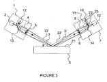
- Figure 3 represents a system for analysing a sample wherein the analysis section 7 comprises an imaging system 11, according to another embodiment of the invention.
- the imaging system 11 comprises a detection surface 19.
- the detection surface 19 detects simultaneously or alternatively the part of the reflected visualization luminous beam 23 and the part of the reflected measurement luminous beam.
- the part of the reflected visualization luminous beam 23 and the part of the reflected measurement luminous beam are focused on the detection surface 19.
- the detection surface 19 is placed on the image plane of the optical system including the second optical means 9 and the separation optical means 14.
- the detection surface 19' can be normal to the visualization direction 25.
- the imaging system 11 can be a CCD camera or a hyperspectral detector or the like.
- the incident measurement luminous beam 3 and the incident visualization luminous beam 22 are inclined with respect to the sample surface 21.
- This inclination leads to an inclination of the image plane which is projected on the detection surface 19.
- the field of view is thus deformed.
- Figure 4 represents four examples of spots, having different dimension, before the projection of the incident measurement luminous beam 3 on the sample surface 21.
- Figure 5 represents four examples of spots, having different dimension, after the projection of the incident measurement luminous beam 3 on the sample surface 21 according to an incidence angle ( ⁇ ) of 70°.
- Figure 5 shows that the field of view is deformed.
- the dimension of the first spot before projection 31 is 10 ⁇ m *20 ⁇ m in figure 4 .
- the dimension of the first spot after projection 35 is 10 ⁇ m *60 ⁇ m in figure 5 .
- the dimension of the second spot before projection 32 is 60 ⁇ m *20 ⁇ m in figure 4 .
- the dimension of the second spot after projection 36 is 60 ⁇ m in figure 5 .
- the dimension of the third spot before projection 33 is 100 ⁇ m *33 ⁇ m in figure 4 .
- the dimension of the third spot after projection 37 is 100 ⁇ m in figure 5 .
- the dimension of the fourth spot before projection 34 is 540 ⁇ m *250 ⁇ m in figure 4 .
- the dimension of the fourth spot after projection 38 is 540 ⁇ m *730 ⁇ m in figure 5 .
- the first spots 31, 35 have dimensions corresponding to minimal dimensions.
- the fourt spots 34, 38 have dimensions corresponding to maximal dimensions.
- the dimension of the field of view is 1.33 mm*1 mm.
- the dimension of the field of view on the sample surface 21 is 1.33 mm*3 mm.
- the aperture angle is 3.4° in the incidence plane and 6.8° in the plane normal to the incidence plane.
- the smallest spot of light 35 is detected on three or four pixels.
- the invention provide, in another embodiment, an inclined imaging system 11', represented in figure 6 .
- the document DE19707926 discloses an ellipsometer wherein a CCD detector is inclined.
- the inclined imaging system 11' has a detection surface 19' which is not normal to the visualization direction 25.
- the detection surface 19' of the inclined imaging system 11' is inclined with respect to the visualization direction 25 according to an inclination angle (a).
- the system for analysing a sample can be adapted in a transmission configuration, as represented in figure 7 .
- the incident measurement luminous beam 3 and the incident imagery luminous beam 22 projected onto the sample surface 21 can be normal or inclined with respect to the sample surface 21.
- the first optical means 5 focuses the incident measurement luminous beam 3 and the incident visualization luminous beam 22 onto the surface of the sample 21 for generating a transmitted measurement luminous beam 3' and a transmitted visualization luminous beam 22'.
- the PSA 8 analyses one or more independent polarization states of the transmitted measurement luminous beam 3' and one or more independent polarization states of the transmitted visualization luminous beam 22'.
- the second optical means 9 focuses the transmitted measurement luminous beam 3' onto the detection system 10 which measures intensity of the transmitted measurement luminous beam 3' as a function of polarization states.
- the separation optical means 14 transmits a part of the transmitted visualization luminous beam 23 and a part of the transmitted imagery luminous beam 22' towards the visualization direction 25.
- the system for analysing a sample 6 can be a monochromatic ellipsometer wherein the detection system 10 is a monochromator.
- It can be a polarimeter or a dichrograph.
- an adapted illumination source 12 such as a xenon source and an adapted imaging system 11 such as a CCD detector or a hyperspectral detector
- an adapted imaging system 11 such as a CCD detector or a hyperspectral detector
- the document US 6,798,511 discloses an imaging ellipsometer using a CCD detector as an imaging system 11.
- the document WO 2005083352 discloses an imaging ellipsometer using a hyperspectral detector as an imaging system 11.
- the group composed of the light source 2, the polarisation state generator PSG 4, the first optical means 5, the second optical means 9, the polarisation state analyser PSA 8 and the detection system 10 forms a "spectroscopic ellipsometer".
- the group composed of the illumination source 12, the polarisation state generator PSG 4, the first optical means 5, the second optical means 9, the polarisation state analyser PSA 8 and the imaging system 11 forms an "imaging ellipsometer".
- the step of visualization of an area localized around the measurement point on the sample surface 21 consists of an acquisition of an ellipsometric image of this area on the sample surface 21.
- the superposition optical means 13 enabling to send the incident visualization luminous beam 22 onto the surface of the sample 21 and the separation optical means 14 enabling to transmit a part of the reflected or transmitted visualization luminous beam 23 towards a visualization direction 25 permit to realise a coupling between said "spectroscopic ellipsometer" and said "imaging ellipsometer".
- a measurement with the "spectroscopic ellipsometer” can be done on a limited area of the sample surface 21.
- This measurement is a polychromatic measurement which supplies several informations concerning the limited area of the sample surface 21 such as the dispersion law of a layer of the sample 6.
- the imaging ellipsometer enable to measure the uniformity of the layer. It is possible to obtain a monochromic ellipsometric image of the layer of the sample 6 in a plane which is parallel to the sample surface 21.
- the hyperspectral detector receives a part of the reflected or transmitted visualization luminous beam 23 to produce a spectroscopic image of one sample layer.
- the illumination source 12 lights an enlarged area of the sample surface 21 or the whole sample surface 21.
- the imaging system 11 detects the enlarged area of the sample surface 21 or the whole sample surface 21.
- All the pixels of the imaging system 11 are simultaneously polarized which leads to reduce the measurement time.
- the measurements with the "spectroscopic ellipsometer” and the “imaging ellipsometer” can be done simultaneously in order to reduce the measurement time or alternatively.
- the superposition optical means 13 and/or the separation optical means 14 can be rotary mirrors.
Landscapes
- Physics & Mathematics (AREA)
- General Physics & Mathematics (AREA)
- Spectroscopy & Molecular Physics (AREA)
- Health & Medical Sciences (AREA)
- Life Sciences & Earth Sciences (AREA)
- Chemical & Material Sciences (AREA)
- Analytical Chemistry (AREA)
- Biochemistry (AREA)
- General Health & Medical Sciences (AREA)
- Immunology (AREA)
- Pathology (AREA)
- Investigating Or Analysing Materials By Optical Means (AREA)
Description
- The invention concerns a system and a process for analysing a sample such as polarimetric or ellipsometric system.
- Polarimetry or ellipsometry are optical techniques that uses polarized light to measure the dielectric properties of a sample. The most common application of polarimetry or ellipsometry is the analysis of very thin films such as layers on wafers.
- The use of polarimetry or ellipsometry is particularly attractive. They are nondestructive techniques, such that it is suitable for in situ observation, and they are extremely sensitive.
- Through the analysis of the state of polarization of the light that interacts with the sample, polarimetry or ellipsometry can yield information about such films like thickness, morphology, or chemical composition.
- The most common polarimeter or ellipsometer configuration is a reflection polarimeter or ellipsometer, although transmission polarimeters or ellipsometers are sometime used.
- Such polarimetric or ellipsometric systems are disclosed in the documents
EP1411333 andUS 5757671 . The surface of a sample is lit by an incident luminous beam and one or more polarization states of this beam is compared to one or more polarization states of the reflected or transmitted luminous beam. - Document
US2004/0233437 describes an ellipsometer system comprising an auxiallary light beam. The incident auxiallary light beam is superimposed with incident ellispsometer beam, but the reflected auxillary beam is extracted out of the reflected ellipsometric beam. The extracted auxiallary beam is directed onto an image pickup device for adjusting sample position. The ellipsometric reflected beam is directed onto a spectrograph. This device does not provide an image of the ellipsometer beam spot on the sample surface. - In most cases, it is needed to visualize the spot of light produced by the incident luminous beam at the sample surface. The spot of the incident luminous beam is positioned at the sample surface to analyse a selected area. With samples having a non homogeneous surface, it is interesting to move the spot for analysing different areas.
- The visualization of the spot is usually realised normally to the sample surface, as illustrated on the
figure 1 of the prior art. This method imposes to use diffusing samples which are capable to diffuse the measurement luminous beam. However, most samples do not diffuse light or diffuse not enough light. - Furthermore, the visualization of the spot of the incident luminous beam at the sample surface or the sample surface is impossible when the measure is realised in enclosed chamber such as electrochemical cell or ablation chamber for example. Such chambers are not provided of transparent porthole disposed over the sample surface.
- One aim of the present invention consists to provide a system for analysing a large variety of samples enabling to visualize the spot of the incident luminous beam on the sample surface and a part of the sample or the whole surface of the sample. With this system, the spot is visualizable on samples which diffuse no light or not enough light. This system is particularly useful to analyse non homogeneous samples.
- Another aim of the present invention is to provide a system for analysing a sample enabling to realise simultaneously or successively spectroscopic ellipsometry (or polarimetry) measurements and ellipsometric (or polarimetric) images of a sample.
- To this end, the invention concerns a system for analysing a sample having at least a surface and comprising:
- an excitation section including:
- o a light source able to emit an incident measurement luminous beam,
- o a polarisation state generator (PSG) able to receive the incident measurement luminous beam and able to produce one or more independent polarization states of the incident measurement luminous beam,
- o first optical means able to focus the incident measurement luminous beam onto the surface of the sample for generating a reflected or transmitted measurement luminous beam having an intensity,
- an analysis section comprising:
- o a polarisation state analyser (PSA) able to analyse one or more independent polarization states of the reflected or transmitted measurement luminous beam,
- o a detection system able to measure intensity of the reflected or transmitted measurement luminous beam as a function of polarization states,
- o second optical means able to focus the reflected or transmitted measurement luminous beam onto the detection system.
- According to the invention:
- the excitation section comprises:
- o an illumination source able to emit an incident visualization luminous beam, the incident visualization luminous beam and the incident measurement luminous beam being simultaneously or alternatively emitted,
- o superposition optical means able to send the incident visualization luminous beam onto the sample surface through an optical path which joins the optical path of the incident measurement luminous beam, in order to generate a reflected or transmitted visualization luminous beam, and
- the analysis section comprises separation optical means able to transmit a part of the reflected or transmitted visualization luminous beam and a part of the reflected or transmitted measurement luminous beam towards a visualization direction.
- According to various embodiments, the present invention also concerns the characteristics below, considered individually or in all their technical possible combinations:
- the analysis section comprises an imaging system having a detection surface, said imaging system receiving the part of the reflected visualization luminous beam and the part of the reflected or transmitted measurement luminous beam on the detection surface,
- the imaging system is an inclined imaging system having a detection surface inclined with respect to the visualization direction according to an inclination angle (α),
- the light source emitting an incident measurement luminous beam and the illumination source emitting an incident visualization luminous beam are light-emitting diodes, the incident visualization luminous beam emitted by said illumination source having an aperture superior to the aperture of the incident measurement luminous beam,
- the PSG and the PSA comprise liquid crystal (LC) variable retarders,
- the detection system measuring intensity of the reflected or transmitted measurement luminous beam is a spectrograph,
- the superposition optical means and the separation optical means are beamsplitters,
- the first optical means is disposed between the PSG and the sample,
- the second optical means is disposed between the sample and the PSA,
- the imaging system is a CCD camera,
- the imaging system is a hyperspectral detector, said hyperspectral detector receiving a part of the reflected or transmitted visualization luminous beam to produce a spectroscopic image of one sample layer.
- Furthermore, the invention concerns a process for analysing a sample comprising the step of realising an ellipsometric measurement at a measurement point on the sample surface.
- According to the invention, the process for analysing a sample comprises a step of visualization of an area localized around the measurement point on the sample surface.
- According to various embodiments, the present invention also concerns the characteristics below, considered individually or in all their technical possible combinations:
- the ellipsometric measurement comprises the operations of:
- o emission of an incident measurement luminous beam,
- o production of one or more independent polarization states of the incident measurement luminous beam,
- o focalisation of the incident measurement luminous beam onto the sample surface for generating a reflected or transmitted measurement luminous beam having an intensity,
- o analyse of one or more independent polarization states of the reflected or transmitted measurement luminous beam,
- o measurement of the intensity of the reflected or transmitted measurement luminous beam as a function of polarization states.
- the visualization of an area localized around the measurement point on the sample surface comprises the operations of:
- o emission of an incident visualization luminous beam,
- o superposition of the incident visualization luminous beam with the incident measurement luminous beam such that the optical path of the incident visualization luminous beam joins the optical path of the incident measurement luminous beam, in order to generate a reflected or transmitted visualization luminous beam, and
- o transmission of a part of the reflected or transmitted visualization luminous beam and a part of the reflected or transmitted measurement luminous beam towards a visualization direction,
- the step of visualization of an area localized around the measurement point on the sample surface comprises the operation of detection of the part of the reflected or transmitted visualization luminous beam and the part of the reflected or transmitted measurement luminous beam towards the visualization direction,
- the step of visualization of an area localized around the measurement point on the sample surface consists of an acquisition of an ellipsometric image of said area on the sample surface.
- The description of the invention is illustrated by the following drawings in which:
-
Figure 1 represents a general configuration of an ellipsometer of the prior art wherein the spot of the incident measurement luminous beam is visualized normally to the sample surface; -
Figure 2 represents a system for analysing a sample wherein the spot of the incident measurement luminous beam and the sample surface are visualized in the direction of the measure, according to one embodiment of the invention ; -
Figure 3 represents a system for analysing a sample wherein the analysis section comprises an imaging system, according to another embodiment of the invention; -
Figure 4 represents four examples of spots, having different dimension, before the projection of the incident measurement luminous beam on the sample surface; -
Figure 5 represents four examples of spots, having different dimension, after the projection of the incident measurement luminous beam on the sample surface according to an incidence angle (θ) of 70°; -
Figure 6 represents a system for analysing a sample comprising an inclined imaging system according to another embodiment of the invention ; -
Figure 7 represents a system for analysing a sample in a transmission configuration ; -
Figure 1 represents a general configuration of an ellipsometer of the prior art wherein the spot of the incident measurement luminous beam is visualized normally to the sample surface. - Said ellipsometer comprises an
excitation section 1 and ananalysis section 7. - The
excitation section 1 comprises alight source 2 emitting an incident measurementluminous beam 3, a polarisation state generator (PSG) 4 and firstoptical means 5. - The incident measurement
luminous beam 3 passes through thePSG 4 and is focused onto thesample surface 21 through the firstoptical means 5. - The incident measurement
luminous beam 3 is reflected onto thesurface 21 producing a reflected measurement luminous beam 3' having an intensity. - The
analysis section 7 of the ellipsometer of the prior art comprises a polarisation state analyser (PSA) 8 enabling to analyse one or more independent polarization states of the reflected measurement luminous beam 3', adetection system 10 measuring intensity of the reflected measurement luminous beam 3' as a function of polarization states and secondoptical means 9. - The reflected measurement luminous beam 3' is send through the second
optical means 9 and passes through thePSA 8 before being focused onto thedetection system 10. - If the
sample 6 diffuses enough the measurement luminous beam 3', a part of the measurementluminous beam 27 is visualized normally to thesurface 21. Thus, the spot of light 29 produced by the projection of the incident measurementluminous beam 3 on thesample surface 21 is visualized directly by user eyes or a CCD camera. - However, with such ellipsometer of prior art, the spot of the incident measurement
luminous beam 29 is only vizualisable for samples diffusing enough light. - Furthermore, the spot of the incident measurement
luminous beam 29 is not vizualisable in apparatus using enclosed chamber. -
Figure 2 represents a system for analysing a sample wherein the spot of the incident measurementluminous beam 29 and thesample surface 21 are visualized in the direction of the measure, according to one embodiment of the invention. - The system for analysing a sample comprises an
excitation section 1 including alight source 2 emitting an incident measurementluminous beam 3, aPSG 4 and firstoptical means 5. - The
excitation section 1 further comprises anillumination source 12 emitting an incident visualizationluminous beam 22. - The incident visualization
luminous beam 22 is an enlarged luminous beam leading to an enlarged spot of the incident visualizationluminous beam 40 on thesample surface 21. Said spot of the incident visualizationluminous beam 40 enable to illumine a part of thesample surface 21 or thewhole sample surface 21. - The method for analysing a
sample 6 comprises the step of realising an ellipsometric measurement at a measurement point on thesample surface 21 and a step of visualization of an area localized around the measurement point on thesample surface 21. - The measurement point on the
sample surface 21 corresponds to the spot of the incident measurementluminous beam 29. The measurement point on thesample surface 21 have a surface which is smaller than the surface of the area localized around this measurement point. - The area localized around the measurement point on the
sample surface 21 corresponds to the spot of the incident visualizationluminous beam 40. - The term visualization means a direct observation by user eyes or an indirect visualization on a detector.
- The aperture of the incident visualization
luminous beam 22 is greater than the aperture of the incident measurementluminous beam 3. - In order to optimize the contrast, the lighting ratio between the incident measurement
luminous beam 3 and the incident visualizationluminous beam 22 can vary from 10 to 100. - The
illumination source 12 can be a light-emitting diode, a multicoloured light-emitting diode or a light having a wide spectral band. - Alternatively, the
illumination source 12 can be associated with a holographic diffuser 17 that homogenizes the incident visualizationluminous beam 22. The holographique diffuser 17 is disposed between theillumination source 12 and the superposition optical means 13. - The
illumination source 12 can be associated with focalisation means for focussing the emitting point of theillumination source 12 on the secondoptical means 9 in order to realise a Kohler type lighting. The focalisation means is disposed between theillumination source 12 and the superposition optical means 13. - The incident visualization
luminous beam 22 is reflected onto a superposition optical means 13 and is directed to thePSG 4. - The superposition optical means 13 can be a beamsplitter or a beam separating cube disposed between the
light source 2 and thePSG 4. - The incident visualization
luminous beam 22 and the incident measurementluminous beam 3 can be emitted simultaneously or alternatively. - After being polarised by the
PSG 4, the incident visualizationluminous beam 22 and the incident measurementluminous beam 3 passes through the firstoptical means 5 which is disposed after thePSG 4 on thefigure 2 . - Alternatively, the first
optical means 5 can be disposed before thePSG 4. The firstoptical means 5 can be lens or the like. - The first
optical means 5 can be such that it permits to obtain a spot of light that is limited by the diffraction limit. - The first
optical means 5 focuses simultaneously or alternatively the incident visualizationluminous beam 22 and the incident measurementluminous beam 3 onto thesample surface 21. - The superposition optical means 13 is disposed and configured such that the optical path of the incident visualization
luminous beam 22 is identical to the optical path of the incident measurementluminous beam 3. Said optical path comprises the path between the superposition optical means 13 and thesurface 21. - The incident visualization
luminous beam 22 and the incident measurementluminous beam 3 make the same incidence angle (θ) with respect to thesample surface 21. In the case of measurements by reflexion, the incidence angle (θ) is comprised between 0° and 90° and is advantageously equal to 70°. - The reflexion of the incident measurement
luminous beam 3 and the incident visualizationluminous beam 22 on thesample surface 21 leads to the generation of a reflected measurement luminous beam 3' and a reflected visualization luminous beam 22', respectively. - The
analysis section 7 comprises adetection system 10 and secondoptical means 9 focusing the reflected measurement luminous beam 3' onto thedetection system 10. - The
detection system 10 can be a photodiode, a photomultiplier, a monochromator or a spectrograph. - The
analysis section 7 comprises aPSA 8 enabling to analyse one or more independent polarization states of the reflected measurement luminous beam 3' and the reflected visualization luminous beam 22'. - The reflected measurement luminous beam 3' passes through the
PSA 8 before being detected by thedetection system 10. - The
analysis section 7 comprises separation optical means 14 enabling to transmit simultaneously or alternatively a part of the reflected visualizationluminous beam 23 and a part the reflected measurement luminous beam towards avisualization direction 25. - The second
optical means 9 can be such that it permits to obtain an image of thesample surface 21 that is limited by the diffraction limit. - As the part of the reflected visualization
luminous beam 23 and the part of the reflected measurement luminous beam are simultaneously transmitted towards thevisualization direction 25, the spot of the measurementluminous beam 29 reflected at thesample surface 21 and a part of thesample surface 21 or thewhole sample surface 21 are simultaneously visualizable by a user (figure 2 ) or on animaging system 11 such a CCD detector (figure 3 ). - The system for analysing a sample can comprise optical means such as lens for focusing the part of the reflected visualization
luminous beam 23 and the part of the reflected measurement luminous beam on the user eyes or on theimaging system 11. - The lighting of the incident visualization
luminous beam 22 should be adjusted in order to avoid the saturation of theimaging system 11 and sufficient to be detected or visualized. - The
analysis section 7 can comprise ahole 30 or a transparent porthole between the user eyes and the separationoptical means 14. The part of the reflected visualizationluminous beam 23 and the part of the reflected measurement luminous beam are transmitted to the user eyes through thehole 30 or the transparent porthole. - The separation optical means 14 can be a beamsplitter or a beam separating cube disposed between the
PSA 8 and thedetection system 10. - As represented in
figure 2 , the secondoptical means 9 is disposed between thesample 6 and thePSA 8. - Alternatively the second
optical means 9 can be disposed between thePSA 8 and the separationoptical means 14. - The optical path of the reflected visualization luminous beam 22' is identical to the optical path of the reflected measurement luminous beam 3'. Said optical path includes the path between the
sample surface 21 and the user eyes or theimaging system 11. - The superposition optical means 13 and the separation optical means 14 enable to integrate the visualization of the spot of the incident measurement
luminous beam 29 and the spot of the incident measurement luminous beam in the optical path of the ellipsometric or polarimetric system. -
- In a
PSG 4 and aPSA 8, the light polarization can be modulated by a variety of devices such as discrete components inserted and then removed from the light path [Bickel W. S. et al.; Am. J. Phys 53 1984 468], rotating retardation plates [Goldstein D. H.; Appl. Opt. 31 1992 6676], rotating compensators [Collins R. W. and Koh J.; J. Opt. Soc. A 16, 1999 1997], Pockels cells [Delplanecke F.; Appl. Opt. 36 1997 5388 and Compain E. and Drévillon B.; Rev. Sci. Instrum. 68 1997 2671] or photoacoustic modulators [Compain E. and Drévillon B.; Rev. Sci. Instrum. 69, 1998 1574] or photoelastic modulator or Faraday cell. - It is possible to use
PSG 4 andPSA 8 including liquid crystal LC variable retarders. Two types of such devices are currently available. First, nematic liquid crystals NLC provide variable retardation with fixed orientation of slow and fast axes, with typical response times of the order of 10 to 100 ms. On the other hand ferroelectric liquid crystals FLC provide fixed retardation, but with slow and fast axis directions which can be electrically switched between two azimuthal angles separated by 45°, in times typically shorter than100 µs.Such PSG 4 andPSA 8 comprise usually a linear polarizer, a retardation plate, and two liquid crystal modulators.Such PSG 4 can generate up to four independent polarization states. - In this case, after reflection of the incident measurement
luminous beam 3 and the incident visualizationluminous beam 22 onto thesample 4, each one of the up to four independent polarization states that had been originally generated by thePSG 4, is successively analysed up to four times by thePSA 8, giving as a result 16 independent intensity measurements necessary for the determination of the Mueller-Stokes matrix of thesample 6. -
Figure 3 represents a system for analysing a sample wherein theanalysis section 7 comprises animaging system 11, according to another embodiment of the invention. - The
imaging system 11 comprises adetection surface 19. Thedetection surface 19 detects simultaneously or alternatively the part of the reflected visualizationluminous beam 23 and the part of the reflected measurement luminous beam. - After being reflected on the separation optical means 14, the part of the reflected visualization
luminous beam 23 and the part of the reflected measurement luminous beam are focused on thedetection surface 19. - The
detection surface 19 is placed on the image plane of the optical system including the secondoptical means 9 and the separationoptical means 14. - The
detection surface 19' can be normal to thevisualization direction 25. - The
imaging system 11 can be a CCD camera or a hyperspectral detector or the like. - In the case of reflexion measurements, the incident measurement
luminous beam 3 and the incident visualizationluminous beam 22 are inclined with respect to thesample surface 21. - This inclination leads to an inclination of the image plane which is projected on the
detection surface 19. The field of view is thus deformed. -
Figure 4 represents four examples of spots, having different dimension, before the projection of the incident measurementluminous beam 3 on thesample surface 21. -
Figure 5 represents four examples of spots, having different dimension, after the projection of the incident measurementluminous beam 3 on thesample surface 21 according to an incidence angle (θ) of 70°.Figure 5 shows that the field of view is deformed. - Before the projection of the incident measurement
luminous beam 3 on thesample surface 21, the dimension of the first spot beforeprojection 31 is 10 µm *20 µm infigure 4 . - After the projection of the incident measurement
luminous beam 3 on thesample surface 21 according to the incidence angle (θ) of 70°, the dimension of the first spot afterprojection 35 is 10 µm *60 µm infigure 5 . - Before the projection of the incident measurement
luminous beam 3 on thesample surface 21, the dimension of the second spot beforeprojection 32 is 60 µm *20 µm infigure 4 . - After the projection of the incident measurement
luminous beam 3 on thesample surface 21 according to the incidence angle (θ) of 70°, the dimension of the second spot afterprojection 36 is 60 µm infigure 5 . - Before the projection of the incident measurement
luminous beam 3 on thesample surface 21, the dimension of the third spot beforeprojection 33 is 100 µm *33 µm infigure 4 . - After the projection of the incident measurement
luminous beam 3 on thesample surface 21 according to the incidence angle (θ) of 70°, the dimension of the third spot afterprojection 37 is 100 µm infigure 5 . - Before the projection of the incident measurement
luminous beam 3 on thesample surface 21, the dimension of the fourth spot beforeprojection 34 is 540 µm *250 µm infigure 4 . - After the projection of the incident measurement
luminous beam 3 on thesample surface 21 according to the incidence angle (θ) of 70°, the dimension of the fourth spot afterprojection 38 is 540 µm *730 µm infigure 5 . - The
first spots - Before the projection of the incident measurement
luminous beam 3 on thesample surface 21, the dimension of the field of view is 1.33 mm*1 mm. - After the projection of the incident measurement
luminous beam 3 on thesample surface 21 according to the incidence angle (θ) of 70°, the dimension of the field of view on thesample surface 21 is 1.33 mm*3 mm. - For these four examples, the aperture angle is 3.4° in the incidence plane and 6.8° in the plane normal to the incidence plane.
- When using a CCD camera as the
imaging system 11, the smallest spot oflight 35 is detected on three or four pixels. - To compensate the inclination of the image plane on which is placed the
detection surface 19, the invention provide, in another embodiment, an inclined imaging system 11', represented infigure 6 . The documentDE19707926 discloses an ellipsometer wherein a CCD detector is inclined. - The inclined imaging system 11' has a
detection surface 19' which is not normal to thevisualization direction 25. Thedetection surface 19' of the inclined imaging system 11' is inclined with respect to thevisualization direction 25 according to an inclination angle (a). - The system for analysing a sample can be adapted in a transmission configuration, as represented in
figure 7 . - In a transmission configuration, the incident measurement
luminous beam 3 and the incident imageryluminous beam 22 projected onto thesample surface 21 can be normal or inclined with respect to thesample surface 21. - While the incident measurement
luminous beam 3 and the incident imageryluminous beam 22 projected onto thesample surface 21 are inclined with respect to thesample surface 21, an inclined imaging system 11' is needed to solve the problem of defocalization due to the projection of the incident measurementluminous beam 3 and the incident imageryluminous beam 22 on thesample surface 21. - The first
optical means 5 focuses the incident measurementluminous beam 3 and the incident visualizationluminous beam 22 onto the surface of thesample 21 for generating a transmitted measurement luminous beam 3' and a transmitted visualization luminous beam 22'. - The
PSA 8 analyses one or more independent polarization states of the transmitted measurement luminous beam 3' and one or more independent polarization states of the transmitted visualization luminous beam 22'. The secondoptical means 9 focuses the transmitted measurement luminous beam 3' onto thedetection system 10 which measures intensity of the transmitted measurement luminous beam 3' as a function of polarization states. - The separation optical means 14 transmits a part of the transmitted visualization
luminous beam 23 and a part of the transmitted imagery luminous beam 22' towards thevisualization direction 25. - The system for analysing a
sample 6 can be a monochromatic ellipsometer wherein thedetection system 10 is a monochromator. - It can be a spectroscopic ellipsometer wherein the
detection system 10 is a spectrograph. - It can be a polarimeter or a dichrograph.
- When using an adapted
illumination source 12 such as a xenon source and an adaptedimaging system 11 such as a CCD detector or a hyperspectral detector, it is possible to realise an ellipsometric or polarimetric image of thesample surface 21. - The document
US 6,798,511 discloses an imaging ellipsometer using a CCD detector as animaging system 11. The documentWO 2005083352 discloses an imaging ellipsometer using a hyperspectral detector as animaging system 11. - The group composed of the
light source 2, the polarisationstate generator PSG 4, the firstoptical means 5, the secondoptical means 9, the polarisationstate analyser PSA 8 and thedetection system 10 forms a "spectroscopic ellipsometer". - And the group composed of the
illumination source 12, the polarisationstate generator PSG 4, the firstoptical means 5, the secondoptical means 9, the polarisationstate analyser PSA 8 and theimaging system 11 forms an "imaging ellipsometer". - The step of visualization of an area localized around the measurement point on the
sample surface 21 consists of an acquisition of an ellipsometric image of this area on thesample surface 21. - The superposition optical means 13 enabling to send the incident visualization
luminous beam 22 onto the surface of thesample 21 and the separation optical means 14 enabling to transmit a part of the reflected or transmitted visualizationluminous beam 23 towards avisualization direction 25 permit to realise a coupling between said "spectroscopic ellipsometer" and said "imaging ellipsometer". - A measurement with the "spectroscopic ellipsometer" can be done on a limited area of the
sample surface 21. This measurement is a polychromatic measurement which supplies several informations concerning the limited area of thesample surface 21 such as the dispersion law of a layer of thesample 6. - Using the dispersion law of the layer, the imaging ellipsometer enable to measure the uniformity of the layer. It is possible to obtain a monochromic ellipsometric image of the layer of the
sample 6 in a plane which is parallel to thesample surface 21. - As the
imaging system 11 is a hyperspectral detector, the hyperspectral detector receives a part of the reflected or transmitted visualizationluminous beam 23 to produce a spectroscopic image of one sample layer. - The
illumination source 12 lights an enlarged area of thesample surface 21 or thewhole sample surface 21. Theimaging system 11 detects the enlarged area of thesample surface 21 or thewhole sample surface 21. - All the pixels of the
imaging system 11 are simultaneously polarized which leads to reduce the measurement time. - The measurements with the "spectroscopic ellipsometer" and the "imaging ellipsometer" can be done simultaneously in order to reduce the measurement time or alternatively.
- In order to realise the measurements alternatively, the superposition optical means 13 and/or the separation optical means 14 can be rotary mirrors.
Claims (9)
- A system for analysing a sample (6) having at least a surface (21) and comprising :- an excitation section (1) including:○ a light source (2) able to emit an incident measurement luminous beam (3),○ a polarisation state generator (PSG) (4) able to receive the incident measurement luminous beam (3) and able to produce one or more independent polarization states of the incident measurement luminous beam (3),○ first optical means (5) able to focus the incident measurement luminous beam (3) onto the sample surface (21) for generating a reflected or transmitted measurement luminous beam (3') having an intensity,○ an illumination source (12) able to emit an incident visualization luminous beam (22),○ superposition optical means (13) able to send the incident visualization luminous beam (22) onto the sample surface (21) through an optical path which joins the optical path of the incident measurement luminous beam (3), in order to generate a reflected or transmitted visualization luminous beam (22'),- an analysis section (7) comprising :characterised in that :○ a polarisation state analyser (PSA) (8) able to analyse one or more independent polarization states of the reflected or transmitted measurement luminous beam (3'),○ a detection system (10) able to measure intensity of the reflected or transmitted measurement luminous beam (3') as a function of polarization states,○ second optical means (9) able to focus the reflected or transmitted measurement luminous beam (3') onto the detection system (10),- the analysis section (7) comprises separation optical means (14) able to transmit a part of the reflected or transmitted visualization luminous beam (23) and a part of the reflected or transmitted measurement luminous beam towards a visualization direction (25).
- System for analysing a sample (6) according to claim 1, characterised in that the analysis section (7) comprises an imaging system (11) having a detection surface (19), said imaging system (11) being able to receive the part of the reflected visualization luminous beam (23) and the part of the reflected or transmitted measurement luminous beam on the detection surface (19).
- System for analysing a sample (6) according to claim 2, characterised in that the imaging system is an inclined imaging system (11') having a detection surface (19') inclined with respect to the visualization direction (25) according to an inclination angle (α).
- System for analysing a sample (6) according to any one of claims 1 to 3, characterised in that :- the light source (2) emitting an incident measurement luminous beam (3) and the illumination source (12) emitting an incident visualization luminous beam (22) are light-emitting diodes, the incident visualization luminous beam (22) emitted by said illumination source (12) having an aperture superior to the aperture of the incident measurement luminous beam (3),- the PSG (4) and the PSA (8) comprise liquid crystal (LC) variable retarders,- the detection system (10) measuring intensity of the reflected or transmitted measurement luminous beam (3') is a spectrograph,- the superposition optical means (13) and the separation optical means (14) are beamsplitters,- the first optical means (5) is disposed between the PSG (4) and the sample (6), and- the second optical means (9) is disposed between the sample (6) and the PSA (8).
- System for analysing a sample (6) according to any one of claims 2 to 4, characterised in that the imaging system (11) is a CCD camera.
- System for analysing a sample (6) according to any one of claims 2 to 4, characterised in that the imaging system (11) is a hyperspectral detector, said hyperspectral detector receiving a part of the reflected or transmitted visualization luminous beam (23) to produce a spectroscopic image of one sample layer.
- Process for analysing a sample (6) comprising the steps of :- realising an ellipsometric measurement at a measurement point on the sample surface (21), wherein the ellipsometric measurement comprises the operations of :and further comprising a step of :○ emission of an incident measurement luminous beam (3),○ production of one or more independent polarization states of the incident measurement luminous beam (3),○ focalisation of the incident measurement luminous beam (3) onto the sample surface (21) for generating a reflected or transmitted measurement luminous beam (3') having an intensity,○ analyse of one or more independent polarization states of the reflected or transmitted measurement luminous beam (3'),○ measurement of the intensity of the reflected or transmitted measurement luminous beam (3') as a function of polarization states,- visualization of an area localized around said measurement point on the sample surface (21), wherein the visualization of an area localized around the measurement point on the sample surface (21) comprises the operations of:characterized in that the visualization of an area localized around said measurement point on the sample surface (21) comprises a step of :○ emission of an incident visualization luminous beam (22),○ superposition of the incident visualization luminous beam (22) with the incident measurement luminous beam (3) such that the optical path of the incident visualization luminous beam (22) joins the optical path of the incident measurement luminous beam (3), in order to generate a reflected or transmitted visualization luminous beam (22'), and○ transmission of a part of the reflected or transmitted visualization luminous beam (23) and a part of the reflected or transmitted measurement luminous beam towards a visualization direction (25).
- Process for analysing a sample (6) according to claim 7, characterised in that the step of visualization of an area localized around the measurement point on the sample surface (21) comprises the operation of detection of the part of the reflected or transmitted visualization luminous beam (23) and the part of the reflected or transmitted measurement luminous beam towards the visualization direction (25).
- Process for analysing a sample (6) according to claim 8, characterised in that the step of visualization of an area localized around the measurement point on the sample surface (21) consists of an acquisition of an ellipsometric image of said area on the sample surface (21).
Priority Applications (5)
| Application Number | Priority Date | Filing Date | Title |
|---|---|---|---|
| DE602007007722T DE602007007722D1 (en) | 2007-01-19 | 2007-01-19 | System and method for analyzing a sample |
| EP07300736A EP1947445B1 (en) | 2007-01-19 | 2007-01-19 | System and process for analysing a sample |
| PCT/EP2008/050596 WO2008087217A1 (en) | 2007-01-19 | 2008-01-18 | System and process for analysing a sample |
| JP2009545942A JP5145357B2 (en) | 2007-01-19 | 2008-01-18 | System and process for analyzing specimens |
| US12/523,417 US8310675B2 (en) | 2007-01-19 | 2008-01-18 | System and process for analyzing a sample |
Applications Claiming Priority (1)
| Application Number | Priority Date | Filing Date | Title |
|---|---|---|---|
| EP07300736A EP1947445B1 (en) | 2007-01-19 | 2007-01-19 | System and process for analysing a sample |
Publications (2)
| Publication Number | Publication Date |
|---|---|
| EP1947445A1 EP1947445A1 (en) | 2008-07-23 |
| EP1947445B1 true EP1947445B1 (en) | 2010-07-14 |
Family
ID=38109904
Family Applications (1)
| Application Number | Title | Priority Date | Filing Date |
|---|---|---|---|
| EP07300736A Ceased EP1947445B1 (en) | 2007-01-19 | 2007-01-19 | System and process for analysing a sample |
Country Status (5)
| Country | Link |
|---|---|
| US (1) | US8310675B2 (en) |
| EP (1) | EP1947445B1 (en) |
| JP (1) | JP5145357B2 (en) |
| DE (1) | DE602007007722D1 (en) |
| WO (1) | WO2008087217A1 (en) |
Families Citing this family (13)
| Publication number | Priority date | Publication date | Assignee | Title |
|---|---|---|---|---|
| US8504140B2 (en) * | 2008-04-08 | 2013-08-06 | Bruker Biospin Corporation | Apparatus and method for fluorescence imaging and tomography using spatially structured illumination |
| US8587781B2 (en) | 2008-09-15 | 2013-11-19 | J.A. Woollam Co., Inc. | View-finder in ellipsometer or the like systems |
| US8339602B1 (en) | 2008-09-15 | 2012-12-25 | J.A. Woollam Co., Inc. | View-finder in ellipsometer or the like systems |
| US9234836B2 (en) * | 2012-11-15 | 2016-01-12 | Fraunhofer-Gesellschaft Zur Foerderung Der Angewandten Forschung E.V. | Measurement of a fiber direction of a carbon fiber material and fabrication of an object in carbon fiber composite technique |
| FR3079028B1 (en) | 2018-03-15 | 2020-05-15 | Horiba France Sas | INSTANTANEOUS ELLIPSOMETER OR SPECTROSCOPIC SCATTEROMETER AND MEASURING METHOD THEREOF |
| FR3087539B1 (en) | 2018-10-18 | 2020-11-20 | Horiba France Sas | MEASURING INSTRUMENT WITH MEASURING SPOT VISUALIZATION SYSTEM AND VISUALIZATION ACCESSORY FOR SUCH A MEASURING INSTRUMENT |
| KR102194562B1 (en) * | 2018-12-27 | 2020-12-23 | 한양대학교 에리카산학협력단 | Spectroscopic Ellipsometer |
| US10801953B2 (en) * | 2019-01-11 | 2020-10-13 | Kla-Tencor Corporation | Semiconductor metrology based on hyperspectral imaging |
| CN110261319B (en) * | 2019-06-24 | 2021-11-16 | 西安理工大学 | Device and method for measuring Mueller matrix spectrum based on four times |
| CN113125456B (en) * | 2019-12-31 | 2024-12-03 | 深圳中科飞测科技股份有限公司 | Light-emitting device, detection method, and detection equipment |
| JP7799430B2 (en) * | 2021-10-25 | 2026-01-15 | キヤノン株式会社 | Image processing device, control method and program |
| CN115014527A (en) * | 2022-06-07 | 2022-09-06 | 上海精测半导体技术有限公司 | Measuring system |
| WO2025059368A1 (en) * | 2023-09-14 | 2025-03-20 | Femtometrix, Inc. | Nonlinear optical stokes ellipsometers |
Family Cites Families (8)
| Publication number | Priority date | Publication date | Assignee | Title |
|---|---|---|---|---|
| JPH06103252B2 (en) * | 1989-05-04 | 1994-12-14 | サーマ―ウェイブ・インク | High resolution ellipsometer apparatus and method |
| IL96483A (en) * | 1990-11-27 | 1995-07-31 | Orbotech Ltd | Optical inspection method and apparatus |
| JPH06147987A (en) * | 1992-11-05 | 1994-05-27 | Canon Inc | Polarization analyzer and misalignment correction method |
| US5764365A (en) * | 1993-11-09 | 1998-06-09 | Nova Measuring Instruments, Ltd. | Two-dimensional beam deflector |
| US6798511B1 (en) * | 2000-10-18 | 2004-09-28 | Regents Of The University Of Minnesota | Imaging ellipsometry |
| EP1411333B1 (en) * | 2002-10-15 | 2006-03-08 | Centre National De La Recherche Scientifique (Cnrs) | A liquid crystal based polarimetric system, a process for its calibration, and a polarimetric measurement process |
| JP2005003666A (en) * | 2003-05-20 | 2005-01-06 | Dainippon Screen Mfg Co Ltd | Spectroscopic ellipsometer |
| WO2005083352A1 (en) * | 2004-02-11 | 2005-09-09 | Filmetrics, Inc. | Method and apparatus for high-speed thickness mapping of patterned thin films |
-
2007
- 2007-01-19 EP EP07300736A patent/EP1947445B1/en not_active Ceased
- 2007-01-19 DE DE602007007722T patent/DE602007007722D1/en active Active
-
2008
- 2008-01-18 WO PCT/EP2008/050596 patent/WO2008087217A1/en not_active Ceased
- 2008-01-18 JP JP2009545942A patent/JP5145357B2/en not_active Expired - Fee Related
- 2008-01-18 US US12/523,417 patent/US8310675B2/en not_active Expired - Fee Related
Also Published As
| Publication number | Publication date |
|---|---|
| US8310675B2 (en) | 2012-11-13 |
| WO2008087217A1 (en) | 2008-07-24 |
| US20100110427A1 (en) | 2010-05-06 |
| EP1947445A1 (en) | 2008-07-23 |
| JP5145357B2 (en) | 2013-02-13 |
| DE602007007722D1 (en) | 2010-08-26 |
| JP2010517003A (en) | 2010-05-20 |
Similar Documents
| Publication | Publication Date | Title |
|---|---|---|
| EP1947445A1 (en) | System and process for analysing a sample | |
| CN112236666B (en) | Transient ellipsometer or scatterometer and related measurement methods | |
| US7742168B2 (en) | Measuring a surface characteristic | |
| JP4514430B2 (en) | Liquid crystal polarization analyzer | |
| US5517312A (en) | Device for measuring the thickness of thin films | |
| US6184984B1 (en) | System for measuring polarimetric spectrum and other properties of a sample | |
| USRE40225E1 (en) | Two-dimensional beam deflector | |
| US6753961B1 (en) | Spectroscopic ellipsometer without rotating components | |
| EP0563221A1 (en) | Method and apparatus for automatic optical inspection | |
| US7248362B2 (en) | Small-spot spectrometry instrument with reduced polarization and multiple-element depolarizer therefor | |
| KR100203345B1 (en) | Simultaneous multiple angle/multiple wavelength ellipsometer and method | |
| US20050007591A1 (en) | Instantaneous polarization measurement system and method | |
| KR101937043B1 (en) | An apparatus and method for measuring the thickness and refractive index of multilayer thin films using angle-resolved spectroscopic reflectometry | |
| CN110715732B (en) | Multifunctional Stokes-Mueller Imaging and Spectral Detection System and Detection Method | |
| US20230042414A1 (en) | Vibration insensitive interferometry for measuring thickness and profile of multilayer thin-film | |
| US7184145B2 (en) | Achromatic spectroscopic ellipsometer with high spatial resolution | |
| KR101825994B1 (en) | Luminance and color meter with wave plate | |
| USRE38153E1 (en) | Two-dimensional beam deflector | |
| KR100395442B1 (en) | Ultra high speed spectroscopic ellipsometer | |
| US20250347625A1 (en) | Apparatus and method for raman or fluorescence spectroscopy having instant polarisation analysis | |
| KR20050024343A (en) | Achromatic spectroscopic ellipsometer with high spatial resolution | |
| EP1642099A1 (en) | Instantaneous polarization measurement system and method |
Legal Events
| Date | Code | Title | Description |
|---|---|---|---|
| PUAI | Public reference made under article 153(3) epc to a published international application that has entered the european phase |
Free format text: ORIGINAL CODE: 0009012 |
|
| AK | Designated contracting states |
Kind code of ref document: A1 Designated state(s): AT BE BG CH CY CZ DE DK EE ES FI FR GB GR HU IE IS IT LI LT LU LV MC NL PL PT RO SE SI SK TR |
|
| AX | Request for extension of the european patent |
Extension state: AL BA HR MK RS |
|
| 17P | Request for examination filed |
Effective date: 20090123 |
|
| 17Q | First examination report despatched |
Effective date: 20090227 |
|
| AKX | Designation fees paid |
Designated state(s): DE FR |
|
| GRAP | Despatch of communication of intention to grant a patent |
Free format text: ORIGINAL CODE: EPIDOSNIGR1 |
|
| GRAS | Grant fee paid |
Free format text: ORIGINAL CODE: EPIDOSNIGR3 |
|
| GRAA | (expected) grant |
Free format text: ORIGINAL CODE: 0009210 |
|
| AK | Designated contracting states |
Kind code of ref document: B1 Designated state(s): DE FR |
|
| REF | Corresponds to: |
Ref document number: 602007007722 Country of ref document: DE Date of ref document: 20100826 Kind code of ref document: P |
|
| PLBE | No opposition filed within time limit |
Free format text: ORIGINAL CODE: 0009261 |
|
| STAA | Information on the status of an ep patent application or granted ep patent |
Free format text: STATUS: NO OPPOSITION FILED WITHIN TIME LIMIT |
|
| 26N | No opposition filed |
Effective date: 20110415 |
|
| REG | Reference to a national code |
Ref country code: DE Ref legal event code: R097 Ref document number: 602007007722 Country of ref document: DE Effective date: 20110415 |
|
| REG | Reference to a national code |
Ref country code: FR Ref legal event code: PLFP Year of fee payment: 10 |
|
| REG | Reference to a national code |
Ref country code: FR Ref legal event code: PLFP Year of fee payment: 11 |
|
| REG | Reference to a national code |
Ref country code: FR Ref legal event code: PLFP Year of fee payment: 12 |
|
| P01 | Opt-out of the competence of the unified patent court (upc) registered |
Effective date: 20230524 |
|
| PGFP | Annual fee paid to national office [announced via postgrant information from national office to epo] |
Ref country code: FR Payment date: 20231201 Year of fee payment: 18 |
|
| PGFP | Annual fee paid to national office [announced via postgrant information from national office to epo] |
Ref country code: DE Payment date: 20231204 Year of fee payment: 18 |
|
| REG | Reference to a national code |
Ref country code: DE Ref legal event code: R119 Ref document number: 602007007722 Country of ref document: DE |
|
| PG25 | Lapsed in a contracting state [announced via postgrant information from national office to epo] |
Ref country code: DE Free format text: LAPSE BECAUSE OF NON-PAYMENT OF DUE FEES Effective date: 20250801 |
|
| PG25 | Lapsed in a contracting state [announced via postgrant information from national office to epo] |
Ref country code: FR Free format text: LAPSE BECAUSE OF NON-PAYMENT OF DUE FEES Effective date: 20250131 |