EP1947410A1 - Evaporative compact high intensity cooler - Google Patents
Evaporative compact high intensity cooler Download PDFInfo
- Publication number
- EP1947410A1 EP1947410A1 EP07255089A EP07255089A EP1947410A1 EP 1947410 A1 EP1947410 A1 EP 1947410A1 EP 07255089 A EP07255089 A EP 07255089A EP 07255089 A EP07255089 A EP 07255089A EP 1947410 A1 EP1947410 A1 EP 1947410A1
- Authority
- EP
- European Patent Office
- Prior art keywords
- coolant
- flow passage
- echic
- heat
- flow passages
- Prior art date
- Legal status (The legal status is an assumption and is not a legal conclusion. Google has not performed a legal analysis and makes no representation as to the accuracy of the status listed.)
- Withdrawn
Links
Images


Classifications
-
- H—ELECTRICITY
- H10—SEMICONDUCTOR DEVICES; ELECTRIC SOLID-STATE DEVICES NOT OTHERWISE PROVIDED FOR
- H10W—GENERIC PACKAGES, INTERCONNECTIONS, CONNECTORS OR OTHER CONSTRUCTIONAL DETAILS OF DEVICES COVERED BY CLASS H10
- H10W40/00—Arrangements for thermal protection or thermal control
- H10W40/70—Fillings or auxiliary members in containers or in encapsulations for thermal protection or control
- H10W40/73—Fillings or auxiliary members in containers or in encapsulations for thermal protection or control for cooling by change of state
-
- F—MECHANICAL ENGINEERING; LIGHTING; HEATING; WEAPONS; BLASTING
- F28—HEAT EXCHANGE IN GENERAL
- F28D—HEAT-EXCHANGE APPARATUS, NOT PROVIDED FOR IN ANOTHER SUBCLASS, IN WHICH THE HEAT-EXCHANGE MEDIA DO NOT COME INTO DIRECT CONTACT
- F28D15/00—Heat-exchange apparatus with the intermediate heat-transfer medium in closed tubes passing into or through the conduit walls ; Heat-exchange apparatus employing intermediate heat-transfer medium or bodies
- F28D15/02—Heat-exchange apparatus with the intermediate heat-transfer medium in closed tubes passing into or through the conduit walls ; Heat-exchange apparatus employing intermediate heat-transfer medium or bodies in which the medium condenses and evaporates, e.g. heat pipes
- F28D15/0233—Heat-exchange apparatus with the intermediate heat-transfer medium in closed tubes passing into or through the conduit walls ; Heat-exchange apparatus employing intermediate heat-transfer medium or bodies in which the medium condenses and evaporates, e.g. heat pipes the conduits having a particular shape, e.g. non-circular cross-section, annular
-
- F—MECHANICAL ENGINEERING; LIGHTING; HEATING; WEAPONS; BLASTING
- F28—HEAT EXCHANGE IN GENERAL
- F28F—DETAILS OF HEAT-EXCHANGE AND HEAT-TRANSFER APPARATUS, OF GENERAL APPLICATION
- F28F2275/00—Fastening; Joining
- F28F2275/06—Fastening; Joining by welding
- F28F2275/061—Fastening; Joining by welding by diffusion bonding
-
- H—ELECTRICITY
- H01—ELECTRIC ELEMENTS
- H01S—DEVICES USING THE PROCESS OF LIGHT AMPLIFICATION BY STIMULATED EMISSION OF RADIATION [LASER] TO AMPLIFY OR GENERATE LIGHT; DEVICES USING STIMULATED EMISSION OF ELECTROMAGNETIC RADIATION IN WAVE RANGES OTHER THAN OPTICAL
- H01S5/00—Semiconductor lasers
- H01S5/02—Structural details or components not essential to laser action
- H01S5/024—Arrangements for thermal management
- H01S5/02469—Passive cooling, e.g. where heat is removed by the housing as a whole or by a heat pipe without any active cooling element like a TEC
-
- H—ELECTRICITY
- H10—SEMICONDUCTOR DEVICES; ELECTRIC SOLID-STATE DEVICES NOT OTHERWISE PROVIDED FOR
- H10W—GENERIC PACKAGES, INTERCONNECTIONS, CONNECTORS OR OTHER CONSTRUCTIONAL DETAILS OF DEVICES COVERED BY CLASS H10
- H10W40/00—Arrangements for thermal protection or thermal control
- H10W40/20—Arrangements for cooling
- H10W40/22—Arrangements for cooling characterised by their shape, e.g. having conical or cylindrical projections
- H10W40/226—Arrangements for cooling characterised by their shape, e.g. having conical or cylindrical projections characterised by projecting parts, e.g. fins to increase surface area
Definitions
- the invention relates to heat sinks and coolers, and more particularly to heat sinks and coolers for limited space applications that require a high degree of heat transfer.
- Very high heat dissipations occur in high power electronic devices such as high-energy laser and the high power microwave devices.
- Surface heat fluxes for laser diodes are approximately 100 to 500 W/cm 2 .
- Microwave interaction and collector cavity heat fluxes can reach 1000 to 2000 W/cm 2 respectively.
- High power electronics such as converters, inverters and motor drives typically have devices that generate heat fluxes of 10 to 40 W/cm 2 at the device level and even higher at the die level.
- High power CPU packages for high performance computers will dissipate as much as 100 W/cm 2 over a footprint of a few square centimetres. All of these devices must operate within acceptable temperature ranges regardless of their heat dissipation. Such devices also demand good surface isothermality for optimum device performance.
- Vapour cycle systems offer two advantages in thermal control at the evaporator. First, pressure level may control temperature due to the pressure-temperature relationship of the saturated vapour. Second, vapour cycle systems exhibit better heat source isothermality than single-phase systems because the coolant changes temperature with heat addition in such systems, such as with the compact high intensity cooler (CHIC) described in USPN 6,167,952 to Downing.
- CHOC compact high intensity cooler
- a high performance evaporator must be capable of accepting high heat fluxes and providing nearly constant temperature heat rejection over the device footprint. Additionally, the thermal resistance of the device should be small, thereby reducing the required lift of the refrigeration system. The evaporator should be capable of evaporating the coolant to high outlet qualities without high pressure drops that would penalise the cycle. Vapour specific volumes are in the range of 140 to 1000 times larger than their liquids. To manage flow velocities and thereby pressure losses during the large changes in volumetric flow, a flow structure with an expanding flow area is required. Flow velocities should remain large enough to maintain shear control, however. These conditions serve to maintain annular flow and wet wall conditions capable of withstanding high heat fluxes to high outlet qualities.
- the invention generally comprises an evaporative compact high intensity cooler (ECHIC) for transferring heat from a heat source along a heat conduction surface of the heat source with a two-phase coolant, comprising: a flow passage labyrinth of flow passages with short conduction paths interrupted by coolant columns that all radiate from at least one coolant supply passage and offer the coolant expanding volume as the coolant evaporates due to absorbing heat within the flow passages from the heat conduction surface to maintain nearly isobaric conditions for the coolant to maintain relatively constant temperature throughout the ECHIC as it absorbs heat from the heat source and limit boundary layer formation within the flow passages to improve heat transfer.
- ECHIC evaporative compact high intensity cooler
- FIGS 1 and 2 are side and top views, respectively, of an evaporative compact high intensity cooler (ECHIC) 2 according to a possible embodiment of the invention that attaches to a heat source 4 along a heat source conduction surface 6.
- the heat source 4 may comprise any high power device with a level of generated heat flux along the surface 6 that requires heat transfer for suitable operation.
- the ECHIC 2 comprises a three-dimensional flow passage labyrinth 8 that directs a flow of coolant to and from the surface 6 of the heat source 4.
- a housing 10 for the ECHIC 2 may have at least one coolant supply port 12 and at least one coolant exhaust port 14 that each couple to the labyrinth 8 for this purpose.
- the flow passage labyrinth 8 preferably comprises a laminated structure made up of several layers of flow passages.
- Figure 3 is a top view of a target layer flow passage lamination 16 that covers a substantial portion of the conduction surface 6 of the heat source 4.
- Figure 4 is a top view of an "even layer” flow passage lamination 18 that covers the target layer flow passage lamination 16.
- Figure 5 is a top view of an "odd layer” flow passage lamination 20 that covers at least one even layer flow passage lamination 16.
- An additional even layer flow passage lamination 18 covers the odd layer flow passage lamination 20. Additional pairs of the odd layer flow passage lamination 20 and the even layer flow passage lamination 18 may cover the additional even layer flow passage lamination 16.
- FIG 6 is a top view of an "interface layer” flow passage lamination 22 that covers one of the even layer flow passage laminations 16 most remote from the surface 6.
- Figure 7 is a top view of a "cover layer” flow passage lamination 24 that covers the interface layer flow passage lamination 22.
- Fabrication of the laminations 16, 18, 20, 22 and 24 may conveniently comprise photo-etched copper laminations. Other fabrication materials and processes may also be suitable, such as micro electro mechanical systems (MEMS) and integrated circuit (IC) processes, depending upon scale.
- MEMS micro electro mechanical systems
- IC integrated circuit
- Figure 1 shows a typical laminated structure for the flow passage labyrinth 8 according to the invention.
- the target layer flow passage lamination 16 covers a substantial portion of the surface 6 of the heat source 4.
- a first one of the even layer flow passage laminations 18 covers the target layer flow passage lamination 16.
- a first one of the odd layer flow passages 20 covers the first even layer flow passage lamination 18.
- a second one of the even layer flow passage laminations 18 covers the first odd layer flow passage lamination 20.
- a second one of the odd layer flow passage laminations 20 covers the second even layer flow passage lamination 18.
- a third one of the even layer flow passage laminations 18 covers the second odd layer flow passage lamination 20.
- the interface layer flow passage lamination 22 covers the third even layer flow passage lamination 18.
- the top layer flow passage lamination 24 covers the interface layer flow passage lamination 22.
- the flow passage labyrinth 8 may conveniently comprise a stack of diffusion-bonded laminations 16, 18, 20, 22 and 24. Alternatively, bonding of the laminations 16, 18, 20, 22 and 24 may be by other processes, such as soldering. Such bonding is desirable to ensure heat transfer through the stack of laminations 16, 18, 20, 22 and 24.
- a liquid coolant that is suitable for two-phase cooling enters the coolant supply port 12 in the housing 10, travels down through a coolant supply passage 26 in the cover layer flow passage lamination 24, a coolant supply passage 28 in the interface layer flow passage lamination 22, a coolant supply passage 30 in each even layer flow passage lamination 18, a coolant supply passage 32 in each odd layer flow passage lamination 20 and a coolant supply passage 34 in the target layer flow passage lamination 16.
- the coolant reaches the surface 6 of the heat source 4, it starts to absorb heat and vaporise. It also starts to propagate through a plurality of innermost cooling passages 36 in the target layer flow passage lamination 16 that couple to and propagate radially from the coolant supply passage 34.
- each innermost cooling passage 36 increases as the coolant propagates through it from the coolant supply passage 34 to an outlet end 38, thereby tending to increase volume and maintain nearly isobaric conditions as the coolant continues to absorb heat and vaporise. This in turn tends to maintain the coolant at a relatively constant temperature as it propagates through each of the innermost cooling passages 36. Since the flow path length is very short, boundary layer development is restricted, resulting in a thin boundary layer that improves heat transfer.
- FIG. 8 is a top view of the first even layer flow passage lamination 18 superimposed over the target layer flow passage lamination 16, wherein an overlap between each innermost cooling passage 36 of the target layer flow passage lamination 16 proximate its outlet end 38 and a corresponding one of the innermost cooling passages 40 of the first even layer flow passage lamination proximate its inlet end 42 forms a corresponding one of a plurality of innermost coolant columns 44.
- the cooling passages radiate generally parallel to the conduction surface 6 of the heat source 4 and the coolant columns extend generally normal to the conduction surface of the heat source.
- each innermost cooling passage 40 As the coolant propagates from the inlet end 42 to an outlet end 46 of each innermost cooling passage 40, the cross-sectional area of each innermost cooling passage 40 increases to an extent that tends to increase volume and maintain nearly isobaric conditions as the coolant continues to absorb heat and vaporise. This in turn tends to maintain the coolant at a relatively constant temperature as it propagates through each of the innermost cooling passages 40. Since the flow path length is very short, boundary layer development is restricted, resulting in a thin boundary layer that improves heat transfer.
- each innermost cooling passage 40 then propagates from its outlet end 46 back into the target layer flow passage lamination 16 and starts a new propagation path along the surface 6 through a corresponding one of a plurality of intermediate cooling passages 48 proximate an inlet end 50.
- Figure 9 is a bottom view of the target flow passage lamination 16 superimposed under the first even layer flow passage lamination 18, wherein an overlap between each innermost cooling passage 40 of the first even layer flow passage lamination 18 proximate its outlet end 46 and a corresponding one of the intermediate cooling passages 48 of the target layer flow passage lamination 16 proximate its inlet end 50 forms a corresponding one of a plurality of primary intermediate coolant columns 52.
- each intermediate cooling passage 48 As the coolant propagates from the inlet end 50 to at least one outlet end 54 of each intermediate cooling passage 48, the cross-sectional area of each intermediate cooling passage 48 increases to an extent that tends to increase volume and maintain nearly isobaric conditions as the coolant continues to absorb heat and vaporise. This in turn tends to maintain the coolant at a relatively constant temperature as it propagates through each of the intermediate cooling passages 48. Since the flow path length is very short, boundary layer development is restricted, resulting in a thin boundary layer that improves heat transfer.
- each intermediate cooling passage 48 then propagates from each outlet end 54 back into the first even layer flow passage lamination 18 and starts a new propagation path through a corresponding one of a plurality of outer cooling passages 56 proximate an inlet end 58.
- An overlap between each intermediate cooling passage 48 of the target layer flow passage lamination 16 proximate each outlet end 54 and each corresponding outer cooling passage 56 of the first even layer flow passage lamination 18 proximate its inlet end 58 forms a corresponding one of a plurality of secondary intermediate coolant columns 60.
- each outer cooling passage 56 As the coolant propagates from the inlet end 58 to at least one outlet end 62 of each outer cooling passage 56, the cross-sectional area of each outer cooling passage 56 increases to an extent that tends to increase volume and maintain nearly isobaric conditions as the coolant continues to absorb heat and vaporise. This in turn tends to maintain the coolant at a relatively constant temperature as it propagates through each of the outer cooling passages 56. Since the flow path length is very short, boundary layer development is restricted, resulting in a thin boundary layer that improves heat transfer.
- each outer cooling passage 56 propagates from each outlet end 62 back into the target layer flow passage lamination 18 and starts a new propagation path along the surface 6 through a corresponding one of a plurality of outer cooling passages 64 proximate an inlet end 66.
- An overlap between each outer cooling passage 56 of the first even layer flow passage lamination 16 proximate each outlet end 58 and each outer cooling passage 64 of the target layer flow passage lamination 16 proximate its inlet end 66 forms a corresponding one of a plurality of tertiary intermediate coolant columns 68.
- each intermediate cooling passage 64 increases to an extent that tends to increase volume and maintain nearly isobaric conditions as the coolant continues to absorb heat and vaporise. This in turn tends to maintain the coolant at a relatively constant temperature as it propagates through each of the outer cooling passages 64. Since the flow path length is very short, boundary layer development is restricted, resulting in a thin boundary layer that improves heat transfer.
- the coolant in each outer cooling passage 64 then propagates from each outlet end through a corresponding one of a plurality of coupling passages 72 in the first even layer flow passage lamination 18 to form a corresponding one of a plurality of outer coolant columns 74.
- Figure 10 is a top view of the first odd layer flow passage lamination 20 superimposed over the first even layer flow passage lamination 18. Coolant from each innermost cooling column 44 passes through a corresponding one of a plurality of coupling passages 76 in the first one of the odd layer flow passage laminations 20. Coolant from each primary intermediate cooling column 52 propagates into a corresponding one of a plurality of inner cooling passages 78 in the first odd layer flow passage lamination 20 proximate an inlet end 80.
- each inner cooling passage 78 As the coolant propagates from the inlet end 80 to at least one outlet end 82 of each inner cooling passage 78, the cross-sectional area of each inner cooling passage 78 increases to an extent that tends to increase volume and maintain nearly isobaric conditions as the coolant continues to absorb heat and vaporise. This in turn tends to maintain the coolant at a relatively constant temperature as it propagates through each of the inner cooling passages 78. Since the flow path length is very short, boundary layer development is restricted, resulting in a thin boundary layer that improves heat transfer. The coolant in each inner cooling passage 78 then propagates from each outlet end 82 into a corresponding one of the secondary intermediate coolant columns 60.
- Coolant from each tertiary intermediate coolant column 68 propagates into a corresponding one of a plurality of outer cooling passages 84 proximate an inlet end 86.
- the cross-sectional area of each outer cooling passage 84 increases to an extent that tends to increase volume and maintain nearly isobaric conditions as the coolant continues to absorb heat and vaporise. This in turn tends to maintain the coolant at a relatively constant temperature as it propagates through each of the outer cooling passages 84. Since the flow path length is very short, boundary layer development is restricted, resulting in a thin boundary layer that improves heat transfer.
- the coolant in each outer cooling passage 84 then propagates from each outlet end 88 into a corresponding one of the outer coolant columns 74.
- Coolant then flows through passages in the second and third even layer flow passage laminations 18 and the second odd layer flow passage lamination 20 as hereinbefore described, as well as for any additional pairs of the odd layer flow passage lamination 20 and the even layer flow passage lamination 18. Coolant from each tertiary intermediate cooling column 68 also propagates into a corresponding one of a plurality of cooling passages 90 in the interface layer cooling passage lamination 22 proximate at least one inlet end 92.
- FIG 11 is a top view of the interface layer 22 superimposed over the third one of the even layer flow passage laminations 18.
- the cross-sectional area of each outer cooling passage 90 increases to an extent that tends to increase volume and maintain nearly isobaric conditions as the coolant continues to absorb heat and vaporise. This in turn tends to maintain the coolant at a relatively constant temperature as it propagates through each of the cooling passages 90. Since the flow path length is very short, boundary layer development is restricted, resulting in a thin boundary layer that improves heat transfer.
- the coolant in each cooling passage 90 then propagates from each outlet end 94 into a corresponding one of the outer coolant columns 74. Finally, coolant in each outer cooling column 74 passes through a corresponding cover layer coupling passage 96 to discharge from the flow passage labyrinth 8.
- the thermal conductance G is the rate of energy transfer per unit area and temperature difference between the coolant and heat source.
- the wetted surface area A is the total surface area of each of the sides, top and bottom of each of the linked flow passages within the flow passage labyrinth 8.
- the laminated construction of the flow passage labyrinth 8 affords low thermal resistances by combining high heat transfer coefficients, (h), abundant area enhancement (A), and good surface efficiency, ⁇ .
- the boundary layer thickness determines the heat transfer coefficient in that it represents the "conduction thickness" in the fluid layer that insulates the cooler bulk flow from the hot wall.
- the flow passage labyrinth 8 minimises the boundary layer with flow passages that have direct liquid impingement, short flow path lengths for re-developing flow, and small channel size. Additionally, the laminations of the flow passage labyrinth 8 permit area enhancement ratios, that is, the wetted heat transfer surface area to the cooler footprint area, typically between approximately 10 and 30 to one.
- the ECHIC 2 for a large-scale heat source 4 may comprise a plurality of flow passage labyrinths 8 ganged together.
- Ganged flow passage labyrinths 8 may comprise individual units or multiple units fabricated within a single large laminated structure with integral headers.
- the shape of the ECHIC 2 may adapt to the shape of the heat source 4.
- the ECHIC 2 for a heat source 4 that has a generally circular rather than square heat source conduction surface 6 may have a cylindrical instead of a rectangular shape to better conform to the heat source 4.
- the ECHIC 2 extends the advantages of the bonded laminate technology to two-phase cooling.
- the bonded lamination of the flow passage labyrinth 8 allows a large wetted surface area for heat transfer to be close to the heat source 4. Because the surface areas of the coolant flow passages within ECHIC 2 are conductively close to the heat source 4 it is highly efficient in dissipating heat.
- Two-phase cooling systems greatly reduce coolant flow requirements through utilisation of the latent heat of coolants.
- the challenge in designing an evaporator for high outlet qualities is accommodating the large volumetric change that occurs during evaporation.
- the ECHIC 2 provides increasing flow area by using expanding areas in the radial and axially flow directions as the coolant propagates through the coolant flow passages and columns in the flow passage labyrinth 8. This flow arrangement limits flow velocities whilst still maintaining shear driven flow,
- the ECHIC 2 achieves excellent heat transfer from the heat source 4 because the multiple laminate construction with numerous small linked flow passages provides wetted surface areas many times larger than the base footprint of the ECHIC 2 on the surface 6 of the heat source 4. This is because the total wetted surface area comprises the total surface area of the sides, top and bottom of each of the linked flow passages. Furthermore, the short flow paths of each flow passage within the flow passage labyrinth 8 restarts boundary layers at the inlet end of each flow passage, thereby limiting the conduction thickness of the boundary layers, resulting in high heat transfer coefficients. Finally, the compact structure of the thin laminations within the flow passage labyrinth 8 inherently has short conduction paths, yielding high heat transfer fin efficiencies.
- the ECHIC 2 is useful in open and closed cooling cycles, as well as in a vapour compression cooling cycle. Due to the large heat of vaporisation, an open cooling cycle may use water as the liquid coolant.
- the open cooling cycle may simply vent wet steam discharged from the ECHIC 2 or it may separate the water from it and vent the dry steam.
- the closed cycle may also use water as the liquid coolant wherein it may condense the wet steam discharged from the ECHIC 2 in a condenser and recirculate the condensed water through the ECHIC 2.
- the ECHIC 2 may also cool the heat source 4 under standby and low power conditions in a single-phase cooling cycle, such as with water as the liquid coolant. As the heat source 4 increases dissipated heat under normal operating conditions, the liquid coolant, such as water, may then vaporise, switching the ECHIC 2 to an efficient two-phase cooling cycle.
Landscapes
- Engineering & Computer Science (AREA)
- Life Sciences & Earth Sciences (AREA)
- Sustainable Development (AREA)
- Physics & Mathematics (AREA)
- Thermal Sciences (AREA)
- Mechanical Engineering (AREA)
- General Engineering & Computer Science (AREA)
- Cooling Or The Like Of Semiconductors Or Solid State Devices (AREA)
Abstract
Description
- The invention relates to heat sinks and coolers, and more particularly to heat sinks and coolers for limited space applications that require a high degree of heat transfer.
- Very high heat dissipations occur in high power electronic devices such as high-energy laser and the high power microwave devices. Surface heat fluxes for laser diodes are approximately 100 to 500 W/cm2. Microwave interaction and collector cavity heat fluxes can reach 1000 to 2000 W/cm2 respectively. High power electronics such as converters, inverters and motor drives typically have devices that generate heat fluxes of 10 to 40 W/cm2 at the device level and even higher at the die level. High power CPU packages for high performance computers will dissipate as much as 100 W/cm2 over a footprint of a few square centimetres. All of these devices must operate within acceptable temperature ranges regardless of their heat dissipation. Such devices also demand good surface isothermality for optimum device performance. Where the ultimate heat sink is at a temperature level that is too high for direct or cascaded loop cooling, rejection of device waste heat to the heat sink requires thermal pumping to a higher temperature level. An efficient refrigeration system is a vapour cycle wherein an evaporator absorbs heat at a lower temperature and a loop condenser rejects it at a higher temperature. Vapour cycle systems offer two advantages in thermal control at the evaporator. First, pressure level may control temperature due to the pressure-temperature relationship of the saturated vapour. Second, vapour cycle systems exhibit better heat source isothermality than single-phase systems because the coolant changes temperature with heat addition in such systems, such as with the compact high intensity cooler (CHIC) described in USPN 6,167,952 to Downing. Given these and other advantages of two-phase heat absorption, a high performance evaporator must be capable of accepting high heat fluxes and providing nearly constant temperature heat rejection over the device footprint. Additionally, the thermal resistance of the device should be small, thereby reducing the required lift of the refrigeration system. The evaporator should be capable of evaporating the coolant to high outlet qualities without high pressure drops that would penalise the cycle. Vapour specific volumes are in the range of 140 to 1000 times larger than their liquids. To manage flow velocities and thereby pressure losses during the large changes in volumetric flow, a flow structure with an expanding flow area is required. Flow velocities should remain large enough to maintain shear control, however. These conditions serve to maintain annular flow and wet wall conditions capable of withstanding high heat fluxes to high outlet qualities.
- Some high energy systems that have short duty cycles make expendable coolants an attractive solution to energy management. In this case, stored liquid coolant may evaporate in the evaporator and then vent in an open cycle arrangement. The desired features of an evaporator for this open cycle system are identical to the closed cycle heat absorber.
- The invention generally comprises an evaporative compact high intensity cooler (ECHIC) for transferring heat from a heat source along a heat conduction surface of the heat source with a two-phase coolant, comprising: a flow passage labyrinth of flow passages with short conduction paths interrupted by coolant columns that all radiate from at least one coolant supply passage and offer the coolant expanding volume as the coolant evaporates due to absorbing heat within the flow passages from the heat conduction surface to maintain nearly isobaric conditions for the coolant to maintain relatively constant temperature throughout the ECHIC as it absorbs heat from the heat source and limit boundary layer formation within the flow passages to improve heat transfer.
-
-
Figure 1 is a side view of an Evaporative Compact High Intensity Cooler (ECHIC) according to a possible embodiment of the invention that transfers heat from a heat source along a heat source conduction surface. -
Figure 2 is a top view of the ECHIC according to the possible embodiment of the invention shown inFigure 1 . -
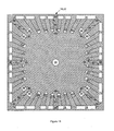
Figure 3 is a top view of a target layer flow passage lamination within the ECHIC that covers a substantial portion of the conduction surface of the heat source shown inFigures 1 and 2 . -
Figure 4 is an "even layer" flow passage lamination that covers the target layer flow passage lamination. -
Figure 5 is a top view of an "odd layer" flow passage lamination that covers at least one even layer flow passage lamination. -
Figure 6 is a top view of an "interface layer" flow passage lamination that covers one of the even layer flow passage laminations most remote from the conduction surface of the heat source. -
Figure 7 is a top view of a "cover layer" flow passage lamination that covers the interface layer flow passage lamination. -
Figure 8 is a top view of the first even layer flow passage lamination superimposed over the target layer flow passage lamination. -
Figure 9 is a bottom view of the target flow passage lamination superimposed under the first even layer flow passage lamination. -
Figure 10 is a top view of the first odd layer flow passage lamination superimposed over the first even layer flow passage lamination. -
Figure 11 is a top view of theinterface layer 22 superimposed over the third one of the even layerflow passage laminations 18. -
Figures 1 and 2 are side and top views, respectively, of an evaporative compact high intensity cooler (ECHIC) 2 according to a possible embodiment of the invention that attaches to aheat source 4 along a heatsource conduction surface 6. Theheat source 4 may comprise any high power device with a level of generated heat flux along thesurface 6 that requires heat transfer for suitable operation. The ECHIC 2 comprises a three-dimensionalflow passage labyrinth 8 that directs a flow of coolant to and from thesurface 6 of theheat source 4. Ahousing 10 for the ECHIC 2 may have at least onecoolant supply port 12 and at least onecoolant exhaust port 14 that each couple to thelabyrinth 8 for this purpose. - The
flow passage labyrinth 8 preferably comprises a laminated structure made up of several layers of flow passages.Figure 3 is a top view of a target layerflow passage lamination 16 that covers a substantial portion of theconduction surface 6 of theheat source 4.Figure 4 is a top view of an "even layer"flow passage lamination 18 that covers the target layerflow passage lamination 16.Figure 5 is a top view of an "odd layer"flow passage lamination 20 that covers at least one even layerflow passage lamination 16. An additional even layerflow passage lamination 18 covers the odd layerflow passage lamination 20. Additional pairs of the odd layerflow passage lamination 20 and the even layerflow passage lamination 18 may cover the additional even layerflow passage lamination 16.Figure 6 is a top view of an "interface layer"flow passage lamination 22 that covers one of the even layerflow passage laminations 16 most remote from thesurface 6.Figure 7 is a top view of a "cover layer"flow passage lamination 24 that covers the interface layerflow passage lamination 22. Fabrication of thelaminations -
Figure 1 shows a typical laminated structure for theflow passage labyrinth 8 according to the invention. The target layerflow passage lamination 16 covers a substantial portion of thesurface 6 of theheat source 4. A first one of the even layerflow passage laminations 18 covers the target layerflow passage lamination 16. A first one of the oddlayer flow passages 20 covers the first even layerflow passage lamination 18. A second one of the even layerflow passage laminations 18 covers the first odd layerflow passage lamination 20. A second one of the odd layerflow passage laminations 20 covers the second even layerflow passage lamination 18. A third one of the even layerflow passage laminations 18 covers the second odd layerflow passage lamination 20. The interface layerflow passage lamination 22 covers the third even layerflow passage lamination 18. Finally, the top layerflow passage lamination 24 covers the interface layerflow passage lamination 22. Theflow passage labyrinth 8 may conveniently comprise a stack of diffusion-bondedlaminations laminations laminations - Referring to
Figures 1 through 7 together, a liquid coolant that is suitable for two-phase cooling enters thecoolant supply port 12 in thehousing 10, travels down through acoolant supply passage 26 in the cover layerflow passage lamination 24, acoolant supply passage 28 in the interface layerflow passage lamination 22, acoolant supply passage 30 in each even layerflow passage lamination 18, acoolant supply passage 32 in each odd layerflow passage lamination 20 and acoolant supply passage 34 in the target layerflow passage lamination 16. Once the coolant reaches thesurface 6 of theheat source 4, it starts to absorb heat and vaporise. It also starts to propagate through a plurality of innermost cooling passages 36 in the target layerflow passage lamination 16 that couple to and propagate radially from thecoolant supply passage 34. - Since the quality (vapour quality) of the coolant starts to increase as the coolant vaporises, the volume of the coolant increases as it propagates through the innermost cooling passages 36. The cross-sectional area of each innermost cooling passage 36 increases as the coolant propagates through it from the
coolant supply passage 34 to an outlet end 38, thereby tending to increase volume and maintain nearly isobaric conditions as the coolant continues to absorb heat and vaporise. This in turn tends to maintain the coolant at a relatively constant temperature as it propagates through each of the innermost cooling passages 36. Since the flow path length is very short, boundary layer development is restricted, resulting in a thin boundary layer that improves heat transfer. - The coolant in each innermost cooling passage 36 then propagates from its outlet end 38 into the first even layer
flow passage lamination 18 and starts a new propagation path through a corresponding one of a plurality of innermost cooling passages 40 proximate an inlet end 42.Figure 8 is a top view of the first even layerflow passage lamination 18 superimposed over the target layerflow passage lamination 16, wherein an overlap between each innermost cooling passage 36 of the target layerflow passage lamination 16 proximate its outlet end 38 and a corresponding one of the innermost cooling passages 40 of the first even layer flow passage lamination proximate its inlet end 42 forms a corresponding one of a plurality of innermost coolant columns 44. - The cooling passages radiate generally parallel to the
conduction surface 6 of theheat source 4 and the coolant columns extend generally normal to the conduction surface of the heat source. - As the coolant propagates from the inlet end 42 to an outlet end 46 of each innermost cooling passage 40, the cross-sectional area of each innermost cooling passage 40 increases to an extent that tends to increase volume and maintain nearly isobaric conditions as the coolant continues to absorb heat and vaporise. This in turn tends to maintain the coolant at a relatively constant temperature as it propagates through each of the innermost cooling passages 40. Since the flow path length is very short, boundary layer development is restricted, resulting in a thin boundary layer that improves heat transfer.
- The coolant in each innermost cooling passage 40 then propagates from its outlet end 46 back into the target layer
flow passage lamination 16 and starts a new propagation path along thesurface 6 through a corresponding one of a plurality of intermediate cooling passages 48 proximate an inlet end 50.Figure 9 is a bottom view of the targetflow passage lamination 16 superimposed under the first even layerflow passage lamination 18, wherein an overlap between each innermost cooling passage 40 of the first even layerflow passage lamination 18 proximate its outlet end 46 and a corresponding one of the intermediate cooling passages 48 of the target layerflow passage lamination 16 proximate its inlet end 50 forms a corresponding one of a plurality of primaryintermediate coolant columns 52. - As the coolant propagates from the inlet end 50 to at least one outlet end 54 of each intermediate cooling passage 48, the cross-sectional area of each intermediate cooling passage 48 increases to an extent that tends to increase volume and maintain nearly isobaric conditions as the coolant continues to absorb heat and vaporise. This in turn tends to maintain the coolant at a relatively constant temperature as it propagates through each of the intermediate cooling passages 48. Since the flow path length is very short, boundary layer development is restricted, resulting in a thin boundary layer that improves heat transfer.
- The coolant in each intermediate cooling passage 48 then propagates from each outlet end 54 back into the first even layer
flow passage lamination 18 and starts a new propagation path through a corresponding one of a plurality of outer cooling passages 56 proximate an inlet end 58. An overlap between each intermediate cooling passage 48 of the target layerflow passage lamination 16 proximate each outlet end 54 and each corresponding outer cooling passage 56 of the first even layerflow passage lamination 18 proximate its inlet end 58 forms a corresponding one of a plurality of secondaryintermediate coolant columns 60. - As the coolant propagates from the inlet end 58 to at least one outlet end 62 of each outer cooling passage 56, the cross-sectional area of each outer cooling passage 56 increases to an extent that tends to increase volume and maintain nearly isobaric conditions as the coolant continues to absorb heat and vaporise. This in turn tends to maintain the coolant at a relatively constant temperature as it propagates through each of the outer cooling passages 56. Since the flow path length is very short, boundary layer development is restricted, resulting in a thin boundary layer that improves heat transfer.
- The coolant in each outer cooling passage 56 then propagates from each outlet end 62 back into the target layer
flow passage lamination 18 and starts a new propagation path along thesurface 6 through a corresponding one of a plurality of outer cooling passages 64 proximate an inlet end 66. An overlap between each outer cooling passage 56 of the first even layerflow passage lamination 16 proximate each outlet end 58 and each outer cooling passage 64 of the target layerflow passage lamination 16 proximate its inlet end 66 forms a corresponding one of a plurality of tertiaryintermediate coolant columns 68. - As the coolant propagates from the inlet end 66 to at least one outlet end 70 of each outer cooling passage 64, the cross sectional area of each intermediate cooling passage 64 increases to an extent that tends to increase volume and maintain nearly isobaric conditions as the coolant continues to absorb heat and vaporise. This in turn tends to maintain the coolant at a relatively constant temperature as it propagates through each of the outer cooling passages 64. Since the flow path length is very short, boundary layer development is restricted, resulting in a thin boundary layer that improves heat transfer. The coolant in each outer cooling passage 64 then propagates from each outlet end through a corresponding one of a plurality of coupling passages 72 in the first even layer
flow passage lamination 18 to form a corresponding one of a plurality ofouter coolant columns 74. -
Figure 10 is a top view of the first odd layerflow passage lamination 20 superimposed over the first even layerflow passage lamination 18. Coolant from each innermost cooling column 44 passes through a corresponding one of a plurality of coupling passages 76 in the first one of the odd layerflow passage laminations 20. Coolant from each primaryintermediate cooling column 52 propagates into a corresponding one of a plurality of inner cooling passages 78 in the first odd layerflow passage lamination 20 proximate an inlet end 80. As the coolant propagates from the inlet end 80 to at least one outlet end 82 of each inner cooling passage 78, the cross-sectional area of each inner cooling passage 78 increases to an extent that tends to increase volume and maintain nearly isobaric conditions as the coolant continues to absorb heat and vaporise. This in turn tends to maintain the coolant at a relatively constant temperature as it propagates through each of the inner cooling passages 78. Since the flow path length is very short, boundary layer development is restricted, resulting in a thin boundary layer that improves heat transfer. The coolant in each inner cooling passage 78 then propagates from each outlet end 82 into a corresponding one of the secondaryintermediate coolant columns 60. - Coolant from each tertiary
intermediate coolant column 68 propagates into a corresponding one of a plurality of outer cooling passages 84 proximate an inlet end 86. As the coolant propagates from the inlet end 86 to at least one outlet end 88 of each outer cooling passage 84, the cross-sectional area of each outer cooling passage 84 increases to an extent that tends to increase volume and maintain nearly isobaric conditions as the coolant continues to absorb heat and vaporise. This in turn tends to maintain the coolant at a relatively constant temperature as it propagates through each of the outer cooling passages 84. Since the flow path length is very short, boundary layer development is restricted, resulting in a thin boundary layer that improves heat transfer. The coolant in each outer cooling passage 84 then propagates from each outlet end 88 into a corresponding one of theouter coolant columns 74. - Coolant then flows through passages in the second and third even layer
flow passage laminations 18 and the second odd layerflow passage lamination 20 as hereinbefore described, as well as for any additional pairs of the odd layerflow passage lamination 20 and the even layerflow passage lamination 18. Coolant from each tertiaryintermediate cooling column 68 also propagates into a corresponding one of a plurality of cooling passages 90 in the interface layercooling passage lamination 22 proximate at least one inlet end 92. -
Figure 11 is a top view of theinterface layer 22 superimposed over the third one of the even layerflow passage laminations 18. As the coolant propagates from the inlet end 92 to at least oneoutlet end 94 of each cooling passage 90, the cross-sectional area of each outer cooling passage 90 increases to an extent that tends to increase volume and maintain nearly isobaric conditions as the coolant continues to absorb heat and vaporise. This in turn tends to maintain the coolant at a relatively constant temperature as it propagates through each of the cooling passages 90. Since the flow path length is very short, boundary layer development is restricted, resulting in a thin boundary layer that improves heat transfer. The coolant in each cooling passage 90 then propagates from each outlet end 94 into a corresponding one of theouter coolant columns 74. Finally, coolant in eachouter cooling column 74 passes through a corresponding coverlayer coupling passage 96 to discharge from theflow passage labyrinth 8. - The
flow passage labyrinth 8 achieves superior heat transfer by optimising the three factors of thermal conductance represented by the relationship G = ηhA. The thermal conductance G is the rate of energy transfer per unit area and temperature difference between the coolant and heat source. The wetted surface area A is the total surface area of each of the sides, top and bottom of each of the linked flow passages within theflow passage labyrinth 8. The laminated construction of theflow passage labyrinth 8 affords low thermal resistances by combining high heat transfer coefficients, (h), abundant area enhancement (A), and good surface efficiency,η. - High heat transfer coefficients occur in flows that limit the development of the boundary layer. The boundary layer thickness determines the heat transfer coefficient in that it represents the "conduction thickness" in the fluid layer that insulates the cooler bulk flow from the hot wall. The
flow passage labyrinth 8 minimises the boundary layer with flow passages that have direct liquid impingement, short flow path lengths for re-developing flow, and small channel size. Additionally, the laminations of theflow passage labyrinth 8 permit area enhancement ratios, that is, the wetted heat transfer surface area to the cooler footprint area, typically between approximately 10 and 30 to one. Like conventional laminated coolers, theECHIC 2 for a large-scale heat source 4 may comprise a plurality offlow passage labyrinths 8 ganged together. Gangedflow passage labyrinths 8 may comprise individual units or multiple units fabricated within a single large laminated structure with integral headers. Similarly, the shape of theECHIC 2 may adapt to the shape of theheat source 4. For instance, theECHIC 2 for aheat source 4 that has a generally circular rather than square heatsource conduction surface 6 may have a cylindrical instead of a rectangular shape to better conform to theheat source 4. - The
ECHIC 2 extends the advantages of the bonded laminate technology to two-phase cooling. The bonded lamination of theflow passage labyrinth 8 allows a large wetted surface area for heat transfer to be close to theheat source 4. Because the surface areas of the coolant flow passages withinECHIC 2 are conductively close to theheat source 4 it is highly efficient in dissipating heat. Two-phase cooling systems greatly reduce coolant flow requirements through utilisation of the latent heat of coolants. The challenge in designing an evaporator for high outlet qualities is accommodating the large volumetric change that occurs during evaporation. TheECHIC 2 provides increasing flow area by using expanding areas in the radial and axially flow directions as the coolant propagates through the coolant flow passages and columns in theflow passage labyrinth 8. This flow arrangement limits flow velocities whilst still maintaining shear driven flow, - The
ECHIC 2 achieves excellent heat transfer from theheat source 4 because the multiple laminate construction with numerous small linked flow passages provides wetted surface areas many times larger than the base footprint of theECHIC 2 on thesurface 6 of theheat source 4. This is because the total wetted surface area comprises the total surface area of the sides, top and bottom of each of the linked flow passages. Furthermore, the short flow paths of each flow passage within theflow passage labyrinth 8 restarts boundary layers at the inlet end of each flow passage, thereby limiting the conduction thickness of the boundary layers, resulting in high heat transfer coefficients. Finally, the compact structure of the thin laminations within theflow passage labyrinth 8 inherently has short conduction paths, yielding high heat transfer fin efficiencies. - The
ECHIC 2 is useful in open and closed cooling cycles, as well as in a vapour compression cooling cycle. Due to the large heat of vaporisation, an open cooling cycle may use water as the liquid coolant. The open cooling cycle may simply vent wet steam discharged from theECHIC 2 or it may separate the water from it and vent the dry steam. The closed cycle may also use water as the liquid coolant wherein it may condense the wet steam discharged from theECHIC 2 in a condenser and recirculate the condensed water through theECHIC 2. In addition to use in such conventional two-phase cooling cycles, theECHIC 2 may also cool theheat source 4 under standby and low power conditions in a single-phase cooling cycle, such as with water as the liquid coolant. As theheat source 4 increases dissipated heat under normal operating conditions, the liquid coolant, such as water, may then vaporise, switching theECHIC 2 to an efficient two-phase cooling cycle. - The described embodiment of the invention is only an illustrative implementation of the invention wherein changes and substitutions of the various parts and arrangement thereof are within the scope of the invention as set forth in the attached claims.
Claims (20)
- An evaporative compact high intensity cooler (ECHIC) (2) for transferring heat from a heat source (4) along a heat .conduction surface of the heat source with a two-phase coolant, comprising:a flow passage labyrinth (8) of coolant flow passages with short conduction paths interrupted by coolant columns that all radiate from at least one coolant supply passage and offer the coolant expanding volume as the coolant evaporates due to absorbing heat within the flow passages from the heat conduction surface, to maintain nearly isobaric conditions for the coolant thereby to maintain relatively constant temperature throughout the ECHIC as it absorbs heat from the heat source and to limit boundary layer formation within the flow passages to improve heat transfer.
- The ECHIC of Claim 1, wherein the coolant flow passages radiate generally parallel to the conduction surface of the heat source and the coolant columns extend generally normal to the conduction surface of the heat source.
- The ECHIC of Claim 1 or 2, wherein the coolant flow passages expand in cross-sectional area as they radiate away from their respective coolant supply passage.
- The ECHIC of Claim 1, 2 or 3, wherein the flow passage labyrinth (8) comprises a plurality of flow passage laminations (16-24).
- The ECHIC of Claim 4, wherein the plurality of flow passage laminations comprise a stack of diffusion-bonded laminations.
- The ECHIC of Claim 4 or 5, wherein each of the flow passage laminations comprise photo-etched copper laminations.
- The ECHIC of Claim 4, 5 or 6, wherein the flow passage laminations transfer coolant through their respective coolant flow passages by way of the coolant columns.
- The ECHIC of Claim 4, 5, 6 or 7, wherein the coolant flows from the coolant flow passages within each flow passage lamination to the coolant flow passages in adjacent ones of the flow passage laminations by way of the coolant columns.
- The ECHIC of any of Claims 4 to 8, wherein the coolant columns overlap exit and entrance ends of the coolant flow passages in adjacent ones of the flow passage laminations.
- An evaporative compact high intensity cooler (ECHIC) (2) for transferring heat from a heat source (4) along a heat conduction surface (6) of the heat source with a two-phase coolant, comprising:a flow passage labyrinth (8) of coolant flow passages that radiate generally parallel to the conduction surface of the heat source with short conduction paths interrupted by coolant columns which extend generally normal to the conduction surface of the heat source, the coolant flow passages and the coolant columns all radiating from at least one coolant supply passage and the coolant flow passages expanding in cross-sectional area as they radiate away from their respective coolant supply passage to offer the coolant expanding volume as the coolant evaporates due to absorbing heat within the flow passages from the heat conduction surface to maintain nearly isobaric conditions for the coolant to maintain relatively constant temperature throughout the ECHIC as it absorbs heat from the heat source and limit boundary layer formation within the flow passages to improve heat transfer.
- The ECHIC of Claim 10, wherein the flow passage labyrinth (8) comprises a plurality of flow passage laminations (16-24).
- The ECHIC of Claim 11, wherein the plurality of flow passage laminations comprise a stack of diffusion-bonded laminations.
- The ECHIC of Claim 11 or 12, wherein each of the flow passage laminations comprise photo-etched copper laminations.
- The ECHIC of Claim 11, 12 or 13, wherein the flow passage laminations transfer coolant through their respective coolant flow passages by way of the coolant columns.
- The ECHIC of Claim 11, 12, 13 or 14, wherein the coolant flows from the coolant flow passages within each flow passage lamination to the coolant flow passages in adjacent ones of the flow passage laminations by way of the coolant columns.
- The ECHIC of any of Claims 11 to 15, wherein the coolant columns overlap exit and entrance ends of the coolant flow passages in adjacent ones of the flow passage laminations.
- An evaporative compact high intensity cooler (ECHIC) (2) for transferring heat from a heat source (4) along a heat conduction surface (6) of the heat source with a two-phase coolant, comprising:a flow passage labyrinth (8) comprising a stack of diffusion bonded copper flow passage laminations (16-24) that have photo-etched coolant flow passages that radiate generally parallel to the conduction surface of the heat source with short conduction paths interrupted by coolant columns which extend generally normal to the conduction surface of the heat source, the coolant flow passages and the coolant columns all radiating from at least one coolant supply passage and the coolant flow passages expanding in cross-sectional area as they radiate away from their respective coolant supply passage to offer the coolant expanding volume as the coolant evaporates due to absorbing heat within the flow passages from the heat conduction surface to maintain nearly isobaric conditions for the coolant to maintain relatively constant temperature throughout the ECHIC as it absorbs heat from the heat source and limit boundary layer formation within the flow passages to improve heat transfer.
- The ECHIC of Claim 17, wherein the flow passage laminations transfer coolant through their respective coolant flow passages by way of the coolant columns.
- The ECHIC of Claim 17 or 18, wherein the coolant flows from the coolant flow passages within each flow passage lamination to the coolant flow passages in adjacent ones of the flow passage laminations by way of the coolant columns.
- The ECHIC of Claim 17, 18 or 19, wherein the coolant columns overlap exit and entrance ends of the coolant flow passages in adjacent ones of the flow passage laminations.
Applications Claiming Priority (1)
| Application Number | Priority Date | Filing Date | Title |
|---|---|---|---|
| US11/654,446 US8056615B2 (en) | 2007-01-17 | 2007-01-17 | Evaporative compact high intensity cooler |
Publications (1)
| Publication Number | Publication Date |
|---|---|
| EP1947410A1 true EP1947410A1 (en) | 2008-07-23 |
Family
ID=39306443
Family Applications (1)
| Application Number | Title | Priority Date | Filing Date |
|---|---|---|---|
| EP07255089A Withdrawn EP1947410A1 (en) | 2007-01-17 | 2007-12-31 | Evaporative compact high intensity cooler |
Country Status (2)
| Country | Link |
|---|---|
| US (1) | US8056615B2 (en) |
| EP (1) | EP1947410A1 (en) |
Cited By (1)
| Publication number | Priority date | Publication date | Assignee | Title |
|---|---|---|---|---|
| CN110278697A (en) * | 2019-07-24 | 2019-09-24 | 凡己科技(苏州)有限公司 | A kind of heat dissipation can be used for electric machine controller and the monitoring device that radiates |
Families Citing this family (24)
| Publication number | Priority date | Publication date | Assignee | Title |
|---|---|---|---|---|
| JP5178274B2 (en) * | 2008-03-26 | 2013-04-10 | 日本モレックス株式会社 | HEAT PIPE, HEAT PIPE MANUFACTURING METHOD, AND CIRCUIT BOARD WITH HEAT PIPE FUNCTION |
| DE102008029096B4 (en) * | 2008-06-20 | 2010-04-15 | Voith Patent Gmbh | Evaporator for a waste heat recovery system |
| US8659896B2 (en) * | 2010-09-13 | 2014-02-25 | Toyota Motor Engineering & Manufacturing North America, Inc. | Cooling apparatuses and power electronics modules |
| US20120181005A1 (en) * | 2011-01-14 | 2012-07-19 | Robert Scott Downing | Compact high performance condenser |
| US20120206880A1 (en) * | 2011-02-14 | 2012-08-16 | Hamilton Sundstrand Corporation | Thermal spreader with phase change thermal capacitor for electrical cooling |
| TWM424749U (en) * | 2011-10-27 | 2012-03-11 | Enermax Technology Corp | Liquid-cooled heat exchange module improvement |
| US9095075B2 (en) | 2012-11-27 | 2015-07-28 | Hamilton Sundstrand Corporation | Enclosure for electronic components with enhanced cooling |
| US8643173B1 (en) | 2013-01-04 | 2014-02-04 | Toyota Motor Engineering & Manufacturing North America, Inc. | Cooling apparatuses and power electronics modules with single-phase and two-phase surface enhancement features |
| US9131631B2 (en) | 2013-08-08 | 2015-09-08 | Toyota Motor Engineering & Manufacturing North America, Inc. | Jet impingement cooling apparatuses having enhanced heat transfer assemblies |
| KR20150063827A (en) * | 2013-12-02 | 2015-06-10 | 삼성전기주식회사 | Cooling system for power semiconductor module |
| CN106471213B (en) * | 2014-07-09 | 2018-06-26 | 西门子公司 | Impingement jet impingement channel system within the internal cooling system |
| US10638648B2 (en) | 2016-04-28 | 2020-04-28 | Ge Energy Power Conversion Technology Ltd. | Cooling system with pressure regulation |
| US9894815B1 (en) | 2016-08-08 | 2018-02-13 | General Electric Company | Heat removal assembly for use with a power converter |
| JP6291000B2 (en) * | 2016-09-01 | 2018-03-07 | 新光電気工業株式会社 | Loop heat pipe and manufacturing method thereof |
| US10251306B2 (en) * | 2016-09-26 | 2019-04-02 | Asia Vital Components Co., Ltd. | Water cooling heat dissipation structure |
| US10139168B2 (en) * | 2016-09-26 | 2018-11-27 | International Business Machines Corporation | Cold plate with radial expanding channels for two-phase cooling |
| US10681846B2 (en) | 2018-04-19 | 2020-06-09 | Google Llc | Cooling electronic devices in a data center |
| US10645847B2 (en) | 2018-04-20 | 2020-05-05 | Google Llc | Cooling electronic devices in a data center |
| US10966352B2 (en) | 2018-09-24 | 2021-03-30 | Google Llc | Cooling electronic devices in a data center |
| US10548240B1 (en) * | 2019-01-11 | 2020-01-28 | Google Llc | Cooling electronic devices in a data center |
| WO2021114144A1 (en) * | 2019-12-11 | 2021-06-17 | 瑞声声学科技(深圳)有限公司 | Heat pipe and loudspeaker apparatus |
| US11587798B2 (en) * | 2020-01-03 | 2023-02-21 | Rolls-Royce North American Technologies Inc. | High heat flux power electronics cooling design |
| CN112435976B (en) * | 2020-11-06 | 2024-04-16 | 西安交通大学 | Ultra-low flow resistance microchannel radiator based on bionic fractal structure and manufacturing method thereof |
| CN114927922A (en) * | 2022-05-18 | 2022-08-19 | 北京华卓精科科技股份有限公司 | Laser mirror cooling structure and laser mirror |
Citations (4)
| Publication number | Priority date | Publication date | Assignee | Title |
|---|---|---|---|---|
| US20030150599A1 (en) * | 2002-02-08 | 2003-08-14 | Kazutaka Suzuki | Cooling apparatus boiling and condensing refrigerant with effective performance in a titled position |
| US20030159809A1 (en) | 2002-02-26 | 2003-08-28 | Mikros Manufacturing, Inc. | Capillary evaporator |
| US20060144565A1 (en) | 2004-12-30 | 2006-07-06 | Delta Electronics, Inc. | Heat dissipation devices and fabrication methods thereof |
| WO2006107492A2 (en) * | 2005-03-08 | 2006-10-12 | Mikros Manufacturing, Inc. | Capillary condenser/evaporator |
Family Cites Families (26)
| Publication number | Priority date | Publication date | Assignee | Title |
|---|---|---|---|---|
| US3923383A (en) * | 1974-06-12 | 1975-12-02 | Caterpillar Tractor Co | Fluid-cooled laser mirror |
| US4386505A (en) * | 1981-05-01 | 1983-06-07 | The Board Of Trustees Of The Leland Stanford Junior University | Refrigerators |
| US4516632A (en) * | 1982-08-31 | 1985-05-14 | The United States Of America As Represented By The United States Deparment Of Energy | Microchannel crossflow fluid heat exchanger and method for its fabrication |
| GB8910241D0 (en) * | 1989-05-04 | 1989-06-21 | Secretary Trade Ind Brit | Heat exchangers |
| US5265670A (en) * | 1990-04-27 | 1993-11-30 | International Business Machines Corporation | Convection transfer system |
| US5088005A (en) * | 1990-05-08 | 1992-02-11 | Sundstrand Corporation | Cold plate for cooling electronics |
| US6134785A (en) * | 1992-05-18 | 2000-10-24 | The Boeing Company | Method of fabricating an article of manufacture such as a heat exchanger |
| FR2701554B1 (en) * | 1993-02-12 | 1995-05-12 | Transcal | Heat exchanger for electronic components and electro-technical equipment. |
| DE19528116B4 (en) * | 1995-08-01 | 2007-02-15 | Behr Gmbh & Co. Kg | Heat exchanger with plate sandwich structure |
| US6167948B1 (en) * | 1996-11-18 | 2001-01-02 | Novel Concepts, Inc. | Thin, planar heat spreader |
| US6167952B1 (en) | 1998-03-03 | 2001-01-02 | Hamilton Sundstrand Corporation | Cooling apparatus and method of assembling same |
| US6210986B1 (en) * | 1999-09-23 | 2001-04-03 | Sandia Corporation | Microfluidic channel fabrication method |
| US6301109B1 (en) * | 2000-02-11 | 2001-10-09 | International Business Machines Corporation | Isothermal heat sink with cross-flow openings between channels |
| WO2001095688A1 (en) * | 2000-06-05 | 2001-12-13 | The State Of Oregon Acting By And Through The State Board Of Higher Education On Behalf Of The University Of Oregon | Multiscale transport apparatus and methods |
| US6843308B1 (en) * | 2000-12-01 | 2005-01-18 | Atmostat Etudes Et Recherches | Heat exchanger device using a two-phase active fluid, and a method of manufacturing such a device |
| US6942018B2 (en) * | 2001-09-28 | 2005-09-13 | The Board Of Trustees Of The Leland Stanford Junior University | Electroosmotic microchannel cooling system |
| US6827128B2 (en) * | 2002-05-20 | 2004-12-07 | The Board Of Trustees Of The University Of Illinois | Flexible microchannel heat exchanger |
| US7000684B2 (en) * | 2002-11-01 | 2006-02-21 | Cooligy, Inc. | Method and apparatus for efficient vertical fluid delivery for cooling a heat producing device |
| US7017655B2 (en) * | 2003-12-18 | 2006-03-28 | Modine Manufacturing Co. | Forced fluid heat sink |
| US20050189342A1 (en) * | 2004-02-23 | 2005-09-01 | Samer Kabbani | Miniature fluid-cooled heat sink with integral heater |
| US7414843B2 (en) * | 2004-03-10 | 2008-08-19 | Intel Corporation | Method and apparatus for a layered thermal management arrangement |
| US7190580B2 (en) * | 2004-07-01 | 2007-03-13 | International Business Machines Corporation | Apparatus and methods for microchannel cooling of semiconductor integrated circuit packages |
| JP2006054351A (en) * | 2004-08-13 | 2006-02-23 | Fujitsu Ltd | Semiconductor element cooling device |
| US7537047B2 (en) * | 2006-03-23 | 2009-05-26 | Foxconn Technology Co., Ltd. | Liquid-cooling heat sink |
| JP2007266153A (en) * | 2006-03-28 | 2007-10-11 | Sony Corp | Plate-type heat transport device and electronic device |
| US7729118B2 (en) * | 2006-11-03 | 2010-06-01 | Fu Zhun Precision Industry (Shen Zhen) Co., Ltd. | Miniature liquid cooling device having an integral pump |
-
2007
- 2007-01-17 US US11/654,446 patent/US8056615B2/en active Active
- 2007-12-31 EP EP07255089A patent/EP1947410A1/en not_active Withdrawn
Patent Citations (4)
| Publication number | Priority date | Publication date | Assignee | Title |
|---|---|---|---|---|
| US20030150599A1 (en) * | 2002-02-08 | 2003-08-14 | Kazutaka Suzuki | Cooling apparatus boiling and condensing refrigerant with effective performance in a titled position |
| US20030159809A1 (en) | 2002-02-26 | 2003-08-28 | Mikros Manufacturing, Inc. | Capillary evaporator |
| US20060144565A1 (en) | 2004-12-30 | 2006-07-06 | Delta Electronics, Inc. | Heat dissipation devices and fabrication methods thereof |
| WO2006107492A2 (en) * | 2005-03-08 | 2006-10-12 | Mikros Manufacturing, Inc. | Capillary condenser/evaporator |
Cited By (1)
| Publication number | Priority date | Publication date | Assignee | Title |
|---|---|---|---|---|
| CN110278697A (en) * | 2019-07-24 | 2019-09-24 | 凡己科技(苏州)有限公司 | A kind of heat dissipation can be used for electric machine controller and the monitoring device that radiates |
Also Published As
| Publication number | Publication date |
|---|---|
| US8056615B2 (en) | 2011-11-15 |
| US20080169087A1 (en) | 2008-07-17 |
Similar Documents
| Publication | Publication Date | Title |
|---|---|---|
| US8056615B2 (en) | Evaporative compact high intensity cooler | |
| US7604040B2 (en) | Integrated liquid cooled heat sink for electronic components | |
| Kang | Advanced cooling for power electronics | |
| US6615912B2 (en) | Porous vapor valve for improved loop thermosiphon performance | |
| US7369410B2 (en) | Apparatuses for dissipating heat from semiconductor devices | |
| US7077189B1 (en) | Liquid cooled thermosiphon with flexible coolant tubes | |
| US6749013B2 (en) | Heat sink | |
| US20190069444A1 (en) | Phase Change Evaporator with Heat-Dissipating Fins and Phase Change Cooling Device Using the Same | |
| EP2476987A2 (en) | Condenser assembly and thermal management system | |
| AU2008343788A1 (en) | Heat pipes incorporating microchannel heat exchangers | |
| WO2010017091A1 (en) | Microscale cooling apparatus and method | |
| JP2009200472A (en) | Method and apparatus for controlling cooling of variable heat load in heat generator | |
| JP2018194197A (en) | Heat pipe and electronic equipment | |
| US7120022B2 (en) | Loop thermosyphon with wicking structure and semiconductor die as evaporator | |
| KR20190120380A (en) | Thermoelectric pump cascade using multiple printed circuit boards with thermoelectric modules | |
| JP5874935B2 (en) | Flat plate cooling device and method of using the same | |
| CN205090651U (en) | Small -size compressive refrigerating system based on microchannel heat exchanger | |
| CN105299938A (en) | Small-sized compression refrigerating system based on micro-channel heat exchanger | |
| AU2023279639A1 (en) | Hybrid thermosyphon with immersion cooled evaporator | |
| US20070151275A1 (en) | Methods and apparatus for microelectronic cooling using a miniaturized vapor compression system | |
| JP2013033807A (en) | Cooling device and electronic apparatus using the same | |
| CN214581473U (en) | Radiator and air condensing units | |
| WO2016014541A1 (en) | Integration of thermosiphon tubing into accept heat exchanger | |
| Uysal et al. | Futuristic methods of electronics cooling | |
| Skuriat | Direct jet impingement cooling of power electronics |
Legal Events
| Date | Code | Title | Description |
|---|---|---|---|
| PUAI | Public reference made under article 153(3) epc to a published international application that has entered the european phase |
Free format text: ORIGINAL CODE: 0009012 |
|
| AK | Designated contracting states |
Kind code of ref document: A1 Designated state(s): AT BE BG CH CY CZ DE DK EE ES FI FR GB GR HU IE IS IT LI LT LU LV MC MT NL PL PT RO SE SI SK TR |
|
| AX | Request for extension of the european patent |
Extension state: AL BA HR MK RS |
|
| 17P | Request for examination filed |
Effective date: 20081028 |
|
| 17Q | First examination report despatched |
Effective date: 20081201 |
|
| AKX | Designation fees paid |
Designated state(s): DE FR GB |
|
| STAA | Information on the status of an ep patent application or granted ep patent |
Free format text: STATUS: THE APPLICATION HAS BEEN WITHDRAWN |
|
| 18W | Application withdrawn |
Effective date: 20131202 |