EP1946979A1 - Airbag cover with controlled tear lines - Google Patents
Airbag cover with controlled tear lines Download PDFInfo
- Publication number
- EP1946979A1 EP1946979A1 EP07381004A EP07381004A EP1946979A1 EP 1946979 A1 EP1946979 A1 EP 1946979A1 EP 07381004 A EP07381004 A EP 07381004A EP 07381004 A EP07381004 A EP 07381004A EP 1946979 A1 EP1946979 A1 EP 1946979A1
- Authority
- EP
- European Patent Office
- Prior art keywords
- cover
- airbag
- tear lines
- airbag cover
- container body
- Prior art date
- Legal status (The legal status is an assumption and is not a legal conclusion. Google has not performed a legal analysis and makes no representation as to the accuracy of the status listed.)
- Granted
Links
- 239000000463 material Substances 0.000 claims abstract description 10
- 239000004033 plastic Substances 0.000 claims abstract description 6
- 230000002787 reinforcement Effects 0.000 claims description 9
- 229920002725 thermoplastic elastomer Polymers 0.000 claims description 2
- 230000001154 acute effect Effects 0.000 claims 1
- 238000010521 absorption reaction Methods 0.000 description 1
- 230000000694 effects Effects 0.000 description 1
- 230000004048 modification Effects 0.000 description 1
- 238000012986 modification Methods 0.000 description 1
Images

Classifications
-
- B—PERFORMING OPERATIONS; TRANSPORTING
- B60—VEHICLES IN GENERAL
- B60R—VEHICLES, VEHICLE FITTINGS, OR VEHICLE PARTS, NOT OTHERWISE PROVIDED FOR
- B60R21/00—Arrangements or fittings on vehicles for protecting or preventing injuries to occupants or pedestrians in case of accidents or other traffic risks
- B60R21/02—Occupant safety arrangements or fittings, e.g. crash pads
- B60R21/16—Inflatable occupant restraints or confinements designed to inflate upon impact or impending impact, e.g. air bags
- B60R21/20—Arrangements for storing inflatable members in their non-use or deflated condition; Arrangement or mounting of air bag modules or components
- B60R21/215—Arrangements for storing inflatable members in their non-use or deflated condition; Arrangement or mounting of air bag modules or components characterised by the covers for the inflatable member
- B60R21/216—Arrangements for storing inflatable members in their non-use or deflated condition; Arrangement or mounting of air bag modules or components characterised by the covers for the inflatable member comprising tether means for limitation of cover motion during deployment
-
- B—PERFORMING OPERATIONS; TRANSPORTING
- B60—VEHICLES IN GENERAL
- B60R—VEHICLES, VEHICLE FITTINGS, OR VEHICLE PARTS, NOT OTHERWISE PROVIDED FOR
- B60R21/00—Arrangements or fittings on vehicles for protecting or preventing injuries to occupants or pedestrians in case of accidents or other traffic risks
- B60R21/02—Occupant safety arrangements or fittings, e.g. crash pads
- B60R21/16—Inflatable occupant restraints or confinements designed to inflate upon impact or impending impact, e.g. air bags
- B60R21/20—Arrangements for storing inflatable members in their non-use or deflated condition; Arrangement or mounting of air bag modules or components
- B60R21/215—Arrangements for storing inflatable members in their non-use or deflated condition; Arrangement or mounting of air bag modules or components characterised by the covers for the inflatable member
- B60R21/2165—Arrangements for storing inflatable members in their non-use or deflated condition; Arrangement or mounting of air bag modules or components characterised by the covers for the inflatable member characterised by a tear line for defining a deployment opening
Definitions
- the present invention relates to an airbag cover for automotive vehicles.
- Airbag covers having an upper surface including predefined tear lines to facilitate the release of the airbag when its deployment is required to protect a vehicle occupant in the event of a collision are currently known.
- the suitable control thereof is problematic. It must be taken into consideration that the airbag may deploy in a very broad temperature range, e.g. between -35°C and +85°C and that within this range, the behavior of the cover, which is usually made of a plastic material, may be very different since its physical and mechanical properties considerably vary with the temperature.
- Patent document GB 2,314,305 describes an airbag cover having areas with different thicknesses defined by different tear lines.
- Patent document US 5,573,267 describes an airbag cover with reinforcement elements in areas close to the tear lines.
- Patent document US 2004/0262891 describes an airbag cover in which the tear lines have areas with different thicknesses at their end part.
- the objective of the present invention is to provide an airbag cover with efficient control means of the tear lines designed on its outer surface so that the cover breaks in a plurality of flaps facilitating the release of the airbag at the required moment for its deployment.
- an airbag cover for an automotive vehicle formed by a container body provided so as to be fixed to the airbag module and an upper surface of a plastic material provided so as to be visible in the vehicle including a plurality of tear lines on the inner face of said upper surface formed by weakened areas predetermined by the lines where the tear will occur during the deployment of the airbag cushion, said tear lines being designed to form flaps after said deployment which are joined to the cover at the area of such flaps defined between the ends of two tear lines close to the container body, the ends of said tear lines being designed in at least one of said flaps with a curved shape with its end parts aimed towards the inside of said upper surface, and the cover including reinforcement ribs to prevent detachment of the flap, such ribs being located close to said end parts of the tear lines and being joined both to the container body and to the inner part of the upper surface of the cover.
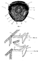
- Figure 1 shows a perspective view of the inside of an airbag cover according to the present invention.
- FIGS 2a and 2b are partial schematic views of an airbag cover according to the present invention while it is inactive and after it is torn due to the deployment of the airbag.
- Figures 3a and 3b show partial sectional views of an airbag cover according to the present invention while it is inactive and after it is torn due to the deployment of the airbag.
- an airbag cover 11 formed by a container body 13 provided so as to be fixed to the airbag module and an upper surface 15 provided to be visible in the vehicle can be seen, in the central part of which a decorative element 14 is arranged which normally bears the logo of the automobile manufacturer.
- the cover 11 is made of a plastic material, and preferably of a thermoplastic elastomer. These materials can be easily processed and allow suitable controlling the size and quality of the parts made using them.
- the inner part of the upper surface 15 includes a plurality of tear lines 21, 22, 23 formed by weakened areas predetermined by the lines where the tearing of the upper surface 15 of the cover will occur during deployment of the cushion of the airbag, said tear lines 21, 22, 23 being designed so that a plurality of flaps 17, 17' is formed on the upper surface 15, allowing the release of the airbag.
- Flap 17 in particular is defined by the tear lines 21, 22, 23 and once these lines are torn, it remains joined to the cover 11 in the area thereof defined between the ends of the two tear lines 21, 23 close to the container body 13, therefore having a hinge function when the airbag is deployed and causes the tear lines 21, 22, 23 to tear.
- the angular ribs 19 are arranged to the side of the end parts 25, 27 of the tear lines 21, 23 and are arranged perpendicular to the upper surface 15 and oblique to the container body 13.
- tear lines 21, 23 are designed with a curved shape with their end parts 25, 27 aimed towards the inside of said upper surface 15.
- Each angular rib 19 and each end part 25, 27 of the tear lines 21, 23 are arranged in turn such that a hypothetical line tangential thereto at the end would be considerably parallel to the angular rib 19.
- the material of the flap 17 bends and elongates without tearing at the end parts 25, 27 of the tear lines 21, 23. Therefore the radius of gyration increases without reaching the elastic limit of the material, preventing detachments.
- the triangular shaped ribs 19 with variable thickness prevent the detachment of the flap 17 at the end parts 25, 27 of the tear lines 21, 23 since they work under tension and torsion at the same time.
- the twisting of the ribs 19 ( Figures 2b and 3b ) resulting from working under torsion in particular entails a significant absorption of energy.
- the reinforcement ribs 19 may have trapezoidal or curved shapes in addition to the triangular shape as a person skilled in the art will understand.
- more than one reinforcement rib 18 can be used next to the end of each tear line.
Landscapes
- Engineering & Computer Science (AREA)
- Mechanical Engineering (AREA)
- Air Bags (AREA)
Abstract
Description
- The present invention relates to an airbag cover for automotive vehicles.
- Airbag covers having an upper surface including predefined tear lines to facilitate the release of the airbag when its deployment is required to protect a vehicle occupant in the event of a collision are currently known.
- It is obviously desirable for the tearing of the airbag cover to occur without any part of such cover becoming detached, and therefore said tear lines are normally designed so that the upper surface can be split into flaps joined to the cover only in areas close to its edges. These flaps must be able to rotate about said joining area, allowing the release of the airbag, and they must remain joined to the cover so as to prevent any detachment of material which may harm the vehicle occupants.
- However, given that the tearing of these flaps through said tear lines may occur in very different conditions, the suitable control thereof is problematic. It must be taken into consideration that the airbag may deploy in a very broad temperature range, e.g. between -35°C and +85°C and that within this range, the behavior of the cover, which is usually made of a plastic material, may be very different since its physical and mechanical properties considerably vary with the temperature.
- Some proposals to that effect are known, and the following documents must be mentioned.
- Patent document
GB 2,314,305 - Patent document
US 5,573,267 describes an airbag cover with reinforcement elements in areas close to the tear lines. - Patent document
US 2004/0262891 describes an airbag cover in which the tear lines have areas with different thicknesses at their end part. - However the automotive industry continuously demands improvements of known solutions and the present invention is aimed at fulfilling this demand.
- The objective of the present invention is to provide an airbag cover with efficient control means of the tear lines designed on its outer surface so that the cover breaks in a plurality of flaps facilitating the release of the airbag at the required moment for its deployment.
- This objective is achieved with an airbag cover for an automotive vehicle formed by a container body provided so as to be fixed to the airbag module and an upper surface of a plastic material provided so as to be visible in the vehicle including a plurality of tear lines on the inner face of said upper surface formed by weakened areas predetermined by the lines where the tear will occur during the deployment of the airbag cushion, said tear lines being designed to form flaps after said deployment which are joined to the cover at the area of such flaps defined between the ends of two tear lines close to the container body, the ends of said tear lines being designed in at least one of said flaps with a curved shape with its end parts aimed towards the inside of said upper surface, and the cover including reinforcement ribs to prevent detachment of the flap, such ribs being located close to said end parts of the tear lines and being joined both to the container body and to the inner part of the upper surface of the cover.
- Other features and advantages of the present invention will be understood from the following detailed description of an illustrative and non-limiting embodiment of its object in relation to the attached drawings.
-
Figure 1 shows a perspective view of the inside of an airbag cover according to the present invention. -
Figures 2a and 2b are partial schematic views of an airbag cover according to the present invention while it is inactive and after it is torn due to the deployment of the airbag. -
Figures 3a and 3b show partial sectional views of an airbag cover according to the present invention while it is inactive and after it is torn due to the deployment of the airbag. - According to
Figure 1 , anairbag cover 11 formed by acontainer body 13 provided so as to be fixed to the airbag module and anupper surface 15 provided to be visible in the vehicle can be seen, in the central part of which adecorative element 14 is arranged which normally bears the logo of the automobile manufacturer. - The
cover 11 is made of a plastic material, and preferably of a thermoplastic elastomer. These materials can be easily processed and allow suitable controlling the size and quality of the parts made using them. - As can be seen in this figure, the inner part of the
upper surface 15 includes a plurality oftear lines upper surface 15 of the cover will occur during deployment of the cushion of the airbag, saidtear lines flaps 17, 17' is formed on theupper surface 15, allowing the release of the airbag. -
Flap 17 in particular is defined by thetear lines cover 11 in the area thereof defined between the ends of the twotear lines container body 13, therefore having a hinge function when the airbag is deployed and causes thetear lines - According to all the figures which show a preferred embodiment of the present invention, it can be seen that the main features thereof for achieving better control of the
tear lines angular reinforcement ribs 19 in the hinge area of theflap 17 and the curved shape of the ends of thetear lines - The
angular ribs 19 are arranged to the side of theend parts tear lines upper surface 15 and oblique to thecontainer body 13. - For their part, the ends of
tear lines end parts upper surface 15. - Each
angular rib 19 and eachend part tear lines angular rib 19. - With these features it is achieved that the material of the
flap 17 bends and elongates without tearing at theend parts tear lines - The triangular
shaped ribs 19 with variable thickness prevent the detachment of theflap 17 at theend parts tear lines Figures 2b and3b ) resulting from working under torsion in particular entails a significant absorption of energy. - The
reinforcement ribs 19 may have trapezoidal or curved shapes in addition to the triangular shape as a person skilled in the art will understand. - In addition, in another embodiment of the present invention, more than one reinforcement rib 18 can be used next to the end of each tear line.
- Although one embodiment of the invention has been described and represented, it is evident that modifications comprised within the scope thereof can be introduced in the invention, and it is not limited to said embodiment but rather to the content of the following claims.
Claims (6)
- An airbag cover (11) for automotive vehicles formed by a container body (13) provided so as to be fixed to the airbag module and an upper surface (15) made of a plastic material so as to be visible in the vehicle including a plurality of tear lines (21, 22, 23) on the inner face of said upper surface (15) formed by weakened areas defined by the lines where its tearing will occur during the deployment of the cushion of the airbag, said tear lines (21, 22, 23) being designed so as to form flaps (17, 17') after said deployment which remain joined to the cover (11) in the area thereof defined between the ends of two tear lines (21, 23) close to the container body (13), characterized in that in at least one of said flaps (17):a) the ends of said tear lines (21, 23) are designed with a curved shape with its end parts (25, 27) aimed towards the inside of said upper surface (15);b) the cover (11) includes reinforcement ribs (19) to prevent the detachment of the flap (17) which are located close to said end parts (25, 27) of the tear lines (21, 23) and are joined both to the container body (13) and to the inner part of the upper surface (15) of the cover (11).
- An airbag cover (11) for automotive vehicles according to claim 1, characterized in that said reinforcement ribs (19) have any of the following shapes: triangular, trapezoidal and curved.
- An airbag cover (11) for automotive vehicles according to claim 2, characterized in that said end parts (25, 27) are designed such that a hypothetical tangent line on its end forms an acute angle with the container body (13).
- An airbag cover (11) for automotive vehicles according to claim 3, characterized in that said reinforcement ribs (19) are arranged in a plane parallel to said hypothetical tangent line.
- An airbag cover (11) for automotive vehicles according to claim 2, characterized in that the cover includes more than one reinforcement rib (19) at the end of each tear line (21, 23).
- An airbag cover (11) for automotive vehicles according to any of the previous claims, characterized in that the plastic material of the upper surface (15) is a thermoplastic elastomer.
Priority Applications (3)
| Application Number | Priority Date | Filing Date | Title |
|---|---|---|---|
| EP07381004A EP1946979B1 (en) | 2007-01-19 | 2007-01-19 | Airbag cover with controlled tear lines |
| ES07381004T ES2392271T3 (en) | 2007-01-19 | 2007-01-19 | Airbag cover with controlled break lines |
| US12/009,621 US20080185822A1 (en) | 2007-01-19 | 2008-01-18 | Airbag cover with controlled tear lines |
Applications Claiming Priority (1)
| Application Number | Priority Date | Filing Date | Title |
|---|---|---|---|
| EP07381004A EP1946979B1 (en) | 2007-01-19 | 2007-01-19 | Airbag cover with controlled tear lines |
Publications (2)
| Publication Number | Publication Date |
|---|---|
| EP1946979A1 true EP1946979A1 (en) | 2008-07-23 |
| EP1946979B1 EP1946979B1 (en) | 2012-08-01 |
Family
ID=38141283
Family Applications (1)
| Application Number | Title | Priority Date | Filing Date |
|---|---|---|---|
| EP07381004A Active EP1946979B1 (en) | 2007-01-19 | 2007-01-19 | Airbag cover with controlled tear lines |
Country Status (3)
| Country | Link |
|---|---|
| US (1) | US20080185822A1 (en) |
| EP (1) | EP1946979B1 (en) |
| ES (1) | ES2392271T3 (en) |
Families Citing this family (3)
| Publication number | Priority date | Publication date | Assignee | Title |
|---|---|---|---|---|
| JP2012071724A (en) * | 2010-09-29 | 2012-04-12 | Toyoda Gosei Co Ltd | Cover for airbag device |
| US9387821B1 (en) | 2015-06-16 | 2016-07-12 | Honda Motor Co., Ltd. | Vehicle restraint systems and methods of use and manufacture thereof |
| CN111605507A (en) * | 2020-04-30 | 2020-09-01 | 奇瑞汽车股份有限公司 | Soft instrument board gasbag apron structure and car |
Citations (6)
| Publication number | Priority date | Publication date | Assignee | Title |
|---|---|---|---|---|
| US5573267A (en) | 1994-06-13 | 1996-11-12 | Takata Corporation | Lid for air bag device |
| GB2314305A (en) | 1994-03-18 | 1997-12-24 | Takata Corp | Airbag module cover member |
| US20040108696A1 (en) * | 2002-12-06 | 2004-06-10 | Daimlerchrysler Corporation | Passenger airbag assembly |
| US20040262891A1 (en) | 2003-06-30 | 2004-12-30 | Takata Corporation | Airbag module and module cover |
| DE102004008726B3 (en) * | 2004-02-23 | 2005-07-21 | Autoliv Development Ab | Airbag module for vehicle has at least one reinforcing ribs arranged to reduce resistance moment of covering cap against deflection |
| US20050269804A1 (en) | 2004-05-27 | 2005-12-08 | Satoshi Yamada | Cover of air bag apparatus and manufacturing method thereof |
-
2007
- 2007-01-19 ES ES07381004T patent/ES2392271T3/en active Active
- 2007-01-19 EP EP07381004A patent/EP1946979B1/en active Active
-
2008
- 2008-01-18 US US12/009,621 patent/US20080185822A1/en not_active Abandoned
Patent Citations (6)
| Publication number | Priority date | Publication date | Assignee | Title |
|---|---|---|---|---|
| GB2314305A (en) | 1994-03-18 | 1997-12-24 | Takata Corp | Airbag module cover member |
| US5573267A (en) | 1994-06-13 | 1996-11-12 | Takata Corporation | Lid for air bag device |
| US20040108696A1 (en) * | 2002-12-06 | 2004-06-10 | Daimlerchrysler Corporation | Passenger airbag assembly |
| US20040262891A1 (en) | 2003-06-30 | 2004-12-30 | Takata Corporation | Airbag module and module cover |
| DE102004008726B3 (en) * | 2004-02-23 | 2005-07-21 | Autoliv Development Ab | Airbag module for vehicle has at least one reinforcing ribs arranged to reduce resistance moment of covering cap against deflection |
| US20050269804A1 (en) | 2004-05-27 | 2005-12-08 | Satoshi Yamada | Cover of air bag apparatus and manufacturing method thereof |
Also Published As
| Publication number | Publication date |
|---|---|
| US20080185822A1 (en) | 2008-08-07 |
| EP1946979B1 (en) | 2012-08-01 |
| ES2392271T3 (en) | 2012-12-07 |
Similar Documents
| Publication | Publication Date | Title |
|---|---|---|
| US8376395B2 (en) | Airbag flap arrangement hinged on a dashboard | |
| US8424905B2 (en) | Interior trim assembly for a motor vehicle and motor vehicle | |
| EP2100781B1 (en) | Vehicle airbaig device and method for manufacturing the same | |
| KR101836712B1 (en) | Hinge device for airbag door of vehicle | |
| US9533649B2 (en) | Seamless passenger airbag system | |
| US8191924B2 (en) | Dashboard | |
| US7992891B2 (en) | Interior panelling part for covering an airbag and method for production thereof | |
| US20080203709A1 (en) | Directional device for deployment of an airbag | |
| CN1856420A (en) | Interior trim part for covering an airbag | |
| US6550803B1 (en) | Covering for a gas bag of a vehicle occupant restraint system | |
| US20170247010A1 (en) | Vehicle seat part | |
| EP1946979B1 (en) | Airbag cover with controlled tear lines | |
| US8662526B2 (en) | Airbag device for passenger's seat | |
| US20210284095A1 (en) | Covering cap for an airbag module and airbag module having such a covering cap | |
| US20220041125A1 (en) | Airbag tether separation | |
| US20130140799A1 (en) | Airbag trajectory control envelope | |
| CN112208478A (en) | Vehicle airbag assembly and related method of forming | |
| US8641084B2 (en) | Ageing-resistant mounting for inflatable airbag module | |
| JP4854325B2 (en) | Airbag door and manufacturing method thereof | |
| US8870218B2 (en) | Motor vehicle lining element comprising a frame for the deployment of an airbag | |
| DE102006049316A1 (en) | Inner lining parts for motor vehicle, has exhaust port is covered by covering linked with swiveling unit at inner lining part and covering has restraining units is connected with inner lining parts | |
| JP2005075141A (en) | Airbag device for vehicle | |
| EP2878497B1 (en) | Airbag cover layer and airbag cover | |
| JP4614796B2 (en) | Airbag door | |
| US8002306B2 (en) | Vehicle interior cladding with airbag cover |
Legal Events
| Date | Code | Title | Description |
|---|---|---|---|
| PUAI | Public reference made under article 153(3) epc to a published international application that has entered the european phase |
Free format text: ORIGINAL CODE: 0009012 |
|
| AK | Designated contracting states |
Kind code of ref document: A1 Designated state(s): AT BE BG CH CY CZ DE DK EE ES FI FR GB GR HU IE IS IT LI LT LU LV MC NL PL PT RO SE SI SK TR |
|
| AX | Request for extension of the european patent |
Extension state: AL BA HR MK RS |
|
| 17P | Request for examination filed |
Effective date: 20080819 |
|
| 17Q | First examination report despatched |
Effective date: 20080926 |
|
| AKX | Designation fees paid |
Designated state(s): AT BE BG CH CY CZ DE DK EE ES FI FR GB GR HU IE IS IT LI LT LU LV MC NL PL PT RO SE SI SK TR |
|
| GRAP | Despatch of communication of intention to grant a patent |
Free format text: ORIGINAL CODE: EPIDOSNIGR1 |
|
| GRAS | Grant fee paid |
Free format text: ORIGINAL CODE: EPIDOSNIGR3 |
|
| GRAA | (expected) grant |
Free format text: ORIGINAL CODE: 0009210 |
|
| AK | Designated contracting states |
Kind code of ref document: B1 Designated state(s): AT BE BG CH CY CZ DE DK EE ES FI FR GB GR HU IE IS IT LI LT LU LV MC NL PL PT RO SE SI SK TR |
|
| REG | Reference to a national code |
Ref country code: GB Ref legal event code: FG4D |
|
| REG | Reference to a national code |
Ref country code: CH Ref legal event code: EP Ref country code: AT Ref legal event code: REF Ref document number: 568488 Country of ref document: AT Kind code of ref document: T Effective date: 20120815 |
|
| REG | Reference to a national code |
Ref country code: IE Ref legal event code: FG4D |
|
| REG | Reference to a national code |
Ref country code: DE Ref legal event code: R096 Ref document number: 602007024303 Country of ref document: DE Effective date: 20120927 |
|
| REG | Reference to a national code |
Ref country code: ES Ref legal event code: FG2A Ref document number: 2392271 Country of ref document: ES Kind code of ref document: T3 Effective date: 20121207 |
|
| REG | Reference to a national code |
Ref country code: NL Ref legal event code: VDEP Effective date: 20120801 |
|
| REG | Reference to a national code |
Ref country code: AT Ref legal event code: MK05 Ref document number: 568488 Country of ref document: AT Kind code of ref document: T Effective date: 20120801 |
|
| REG | Reference to a national code |
Ref country code: LT Ref legal event code: MG4D Effective date: 20120801 |
|
| PG25 | Lapsed in a contracting state [announced via postgrant information from national office to epo] |
Ref country code: LT Free format text: LAPSE BECAUSE OF FAILURE TO SUBMIT A TRANSLATION OF THE DESCRIPTION OR TO PAY THE FEE WITHIN THE PRESCRIBED TIME-LIMIT Effective date: 20120801 Ref country code: FI Free format text: LAPSE BECAUSE OF FAILURE TO SUBMIT A TRANSLATION OF THE DESCRIPTION OR TO PAY THE FEE WITHIN THE PRESCRIBED TIME-LIMIT Effective date: 20120801 Ref country code: CY Free format text: LAPSE BECAUSE OF FAILURE TO SUBMIT A TRANSLATION OF THE DESCRIPTION OR TO PAY THE FEE WITHIN THE PRESCRIBED TIME-LIMIT Effective date: 20120801 Ref country code: IS Free format text: LAPSE BECAUSE OF FAILURE TO SUBMIT A TRANSLATION OF THE DESCRIPTION OR TO PAY THE FEE WITHIN THE PRESCRIBED TIME-LIMIT Effective date: 20121201 Ref country code: AT Free format text: LAPSE BECAUSE OF FAILURE TO SUBMIT A TRANSLATION OF THE DESCRIPTION OR TO PAY THE FEE WITHIN THE PRESCRIBED TIME-LIMIT Effective date: 20120801 |
|
| PG25 | Lapsed in a contracting state [announced via postgrant information from national office to epo] |
Ref country code: SE Free format text: LAPSE BECAUSE OF FAILURE TO SUBMIT A TRANSLATION OF THE DESCRIPTION OR TO PAY THE FEE WITHIN THE PRESCRIBED TIME-LIMIT Effective date: 20120801 Ref country code: LV Free format text: LAPSE BECAUSE OF FAILURE TO SUBMIT A TRANSLATION OF THE DESCRIPTION OR TO PAY THE FEE WITHIN THE PRESCRIBED TIME-LIMIT Effective date: 20120801 Ref country code: SI Free format text: LAPSE BECAUSE OF FAILURE TO SUBMIT A TRANSLATION OF THE DESCRIPTION OR TO PAY THE FEE WITHIN THE PRESCRIBED TIME-LIMIT Effective date: 20120801 Ref country code: PL Free format text: LAPSE BECAUSE OF FAILURE TO SUBMIT A TRANSLATION OF THE DESCRIPTION OR TO PAY THE FEE WITHIN THE PRESCRIBED TIME-LIMIT Effective date: 20120801 Ref country code: PT Free format text: LAPSE BECAUSE OF FAILURE TO SUBMIT A TRANSLATION OF THE DESCRIPTION OR TO PAY THE FEE WITHIN THE PRESCRIBED TIME-LIMIT Effective date: 20121203 Ref country code: GR Free format text: LAPSE BECAUSE OF FAILURE TO SUBMIT A TRANSLATION OF THE DESCRIPTION OR TO PAY THE FEE WITHIN THE PRESCRIBED TIME-LIMIT Effective date: 20121102 Ref country code: BE Free format text: LAPSE BECAUSE OF FAILURE TO SUBMIT A TRANSLATION OF THE DESCRIPTION OR TO PAY THE FEE WITHIN THE PRESCRIBED TIME-LIMIT Effective date: 20120801 |
|
| PG25 | Lapsed in a contracting state [announced via postgrant information from national office to epo] |
Ref country code: NL Free format text: LAPSE BECAUSE OF FAILURE TO SUBMIT A TRANSLATION OF THE DESCRIPTION OR TO PAY THE FEE WITHIN THE PRESCRIBED TIME-LIMIT Effective date: 20120801 |
|
| PG25 | Lapsed in a contracting state [announced via postgrant information from national office to epo] |
Ref country code: EE Free format text: LAPSE BECAUSE OF FAILURE TO SUBMIT A TRANSLATION OF THE DESCRIPTION OR TO PAY THE FEE WITHIN THE PRESCRIBED TIME-LIMIT Effective date: 20120801 Ref country code: CZ Free format text: LAPSE BECAUSE OF FAILURE TO SUBMIT A TRANSLATION OF THE DESCRIPTION OR TO PAY THE FEE WITHIN THE PRESCRIBED TIME-LIMIT Effective date: 20120801 Ref country code: RO Free format text: LAPSE BECAUSE OF FAILURE TO SUBMIT A TRANSLATION OF THE DESCRIPTION OR TO PAY THE FEE WITHIN THE PRESCRIBED TIME-LIMIT Effective date: 20120801 Ref country code: DK Free format text: LAPSE BECAUSE OF FAILURE TO SUBMIT A TRANSLATION OF THE DESCRIPTION OR TO PAY THE FEE WITHIN THE PRESCRIBED TIME-LIMIT Effective date: 20120801 |
|
| PG25 | Lapsed in a contracting state [announced via postgrant information from national office to epo] |
Ref country code: IT Free format text: LAPSE BECAUSE OF FAILURE TO SUBMIT A TRANSLATION OF THE DESCRIPTION OR TO PAY THE FEE WITHIN THE PRESCRIBED TIME-LIMIT Effective date: 20120801 Ref country code: SK Free format text: LAPSE BECAUSE OF FAILURE TO SUBMIT A TRANSLATION OF THE DESCRIPTION OR TO PAY THE FEE WITHIN THE PRESCRIBED TIME-LIMIT Effective date: 20120801 |
|
| PLBE | No opposition filed within time limit |
Free format text: ORIGINAL CODE: 0009261 |
|
| STAA | Information on the status of an ep patent application or granted ep patent |
Free format text: STATUS: NO OPPOSITION FILED WITHIN TIME LIMIT |
|
| 26N | No opposition filed |
Effective date: 20130503 |
|
| PG25 | Lapsed in a contracting state [announced via postgrant information from national office to epo] |
Ref country code: BG Free format text: LAPSE BECAUSE OF FAILURE TO SUBMIT A TRANSLATION OF THE DESCRIPTION OR TO PAY THE FEE WITHIN THE PRESCRIBED TIME-LIMIT Effective date: 20121101 |
|
| REG | Reference to a national code |
Ref country code: DE Ref legal event code: R097 Ref document number: 602007024303 Country of ref document: DE Effective date: 20130503 |
|
| PG25 | Lapsed in a contracting state [announced via postgrant information from national office to epo] |
Ref country code: MC Free format text: LAPSE BECAUSE OF NON-PAYMENT OF DUE FEES Effective date: 20130131 |
|
| REG | Reference to a national code |
Ref country code: CH Ref legal event code: PL |
|
| GBPC | Gb: european patent ceased through non-payment of renewal fee |
Effective date: 20130119 |
|
| REG | Reference to a national code |
Ref country code: IE Ref legal event code: MM4A |
|
| PG25 | Lapsed in a contracting state [announced via postgrant information from national office to epo] |
Ref country code: LI Free format text: LAPSE BECAUSE OF NON-PAYMENT OF DUE FEES Effective date: 20130131 Ref country code: CH Free format text: LAPSE BECAUSE OF NON-PAYMENT OF DUE FEES Effective date: 20130131 |
|
| PG25 | Lapsed in a contracting state [announced via postgrant information from national office to epo] |
Ref country code: GB Free format text: LAPSE BECAUSE OF NON-PAYMENT OF DUE FEES Effective date: 20130119 |
|
| PG25 | Lapsed in a contracting state [announced via postgrant information from national office to epo] |
Ref country code: IE Free format text: LAPSE BECAUSE OF NON-PAYMENT OF DUE FEES Effective date: 20130119 |
|
| PG25 | Lapsed in a contracting state [announced via postgrant information from national office to epo] |
Ref country code: TR Free format text: LAPSE BECAUSE OF FAILURE TO SUBMIT A TRANSLATION OF THE DESCRIPTION OR TO PAY THE FEE WITHIN THE PRESCRIBED TIME-LIMIT Effective date: 20120801 |
|
| PG25 | Lapsed in a contracting state [announced via postgrant information from national office to epo] |
Ref country code: LU Free format text: LAPSE BECAUSE OF NON-PAYMENT OF DUE FEES Effective date: 20130119 Ref country code: HU Free format text: LAPSE BECAUSE OF FAILURE TO SUBMIT A TRANSLATION OF THE DESCRIPTION OR TO PAY THE FEE WITHIN THE PRESCRIBED TIME-LIMIT; INVALID AB INITIO Effective date: 20070119 |
|
| REG | Reference to a national code |
Ref country code: FR Ref legal event code: PLFP Year of fee payment: 10 |
|
| REG | Reference to a national code |
Ref country code: FR Ref legal event code: PLFP Year of fee payment: 11 |
|
| REG | Reference to a national code |
Ref country code: FR Ref legal event code: PLFP Year of fee payment: 12 |
|
| P01 | Opt-out of the competence of the unified patent court (upc) registered |
Effective date: 20230528 |
|
| PGFP | Annual fee paid to national office [announced via postgrant information from national office to epo] |
Ref country code: FR Payment date: 20241209 Year of fee payment: 19 |
|
| PGFP | Annual fee paid to national office [announced via postgrant information from national office to epo] |
Ref country code: DE Payment date: 20250131 Year of fee payment: 19 |
|
| PGFP | Annual fee paid to national office [announced via postgrant information from national office to epo] |
Ref country code: ES Payment date: 20250207 Year of fee payment: 19 |