EP1945940B1 - Deployment apparatus for submerged power plant - Google Patents
Deployment apparatus for submerged power plant Download PDFInfo
- Publication number
- EP1945940B1 EP1945940B1 EP06794769.7A EP06794769A EP1945940B1 EP 1945940 B1 EP1945940 B1 EP 1945940B1 EP 06794769 A EP06794769 A EP 06794769A EP 1945940 B1 EP1945940 B1 EP 1945940B1
- Authority
- EP
- European Patent Office
- Prior art keywords
- power generating
- support structure
- generating apparatus
- alignment
- latching
- Prior art date
- Legal status (The legal status is an assumption and is not a legal conclusion. Google has not performed a legal analysis and makes no representation as to the accuracy of the status listed.)
- Active
Links
Images

Classifications
-
- F—MECHANICAL ENGINEERING; LIGHTING; HEATING; WEAPONS; BLASTING
- F03—MACHINES OR ENGINES FOR LIQUIDS; WIND, SPRING, OR WEIGHT MOTORS; PRODUCING MECHANICAL POWER OR A REACTIVE PROPULSIVE THRUST, NOT OTHERWISE PROVIDED FOR
- F03B—MACHINES OR ENGINES FOR LIQUIDS
- F03B17/00—Other machines or engines
- F03B17/06—Other machines or engines using liquid flow with predominantly kinetic energy conversion, e.g. of swinging-flap type, "run-of-river", "ultra-low head"
- F03B17/061—Other machines or engines using liquid flow with predominantly kinetic energy conversion, e.g. of swinging-flap type, "run-of-river", "ultra-low head" with rotation axis substantially in flow direction
-
- B—PERFORMING OPERATIONS; TRANSPORTING
- B66—HOISTING; LIFTING; HAULING
- B66D—CAPSTANS; WINCHES; TACKLES, e.g. PULLEY BLOCKS; HOISTS
- B66D1/00—Rope, cable, or chain winding mechanisms; Capstans
- B66D1/60—Rope, cable, or chain winding mechanisms; Capstans adapted for special purposes
-
- F—MECHANICAL ENGINEERING; LIGHTING; HEATING; WEAPONS; BLASTING
- F03—MACHINES OR ENGINES FOR LIQUIDS; WIND, SPRING, OR WEIGHT MOTORS; PRODUCING MECHANICAL POWER OR A REACTIVE PROPULSIVE THRUST, NOT OTHERWISE PROVIDED FOR
- F03B—MACHINES OR ENGINES FOR LIQUIDS
- F03B13/00—Adaptations of machines or engines for special use; Combinations of machines or engines with driving or driven apparatus; Power stations or aggregates
- F03B13/10—Submerged units incorporating electric generators or motors
-
- F—MECHANICAL ENGINEERING; LIGHTING; HEATING; WEAPONS; BLASTING
- F03—MACHINES OR ENGINES FOR LIQUIDS; WIND, SPRING, OR WEIGHT MOTORS; PRODUCING MECHANICAL POWER OR A REACTIVE PROPULSIVE THRUST, NOT OTHERWISE PROVIDED FOR
- F03B—MACHINES OR ENGINES FOR LIQUIDS
- F03B13/00—Adaptations of machines or engines for special use; Combinations of machines or engines with driving or driven apparatus; Power stations or aggregates
- F03B13/12—Adaptations of machines or engines for special use; Combinations of machines or engines with driving or driven apparatus; Power stations or aggregates characterised by using wave or tide energy
- F03B13/26—Adaptations of machines or engines for special use; Combinations of machines or engines with driving or driven apparatus; Power stations or aggregates characterised by using wave or tide energy using tide energy
- F03B13/264—Adaptations of machines or engines for special use; Combinations of machines or engines with driving or driven apparatus; Power stations or aggregates characterised by using wave or tide energy using tide energy using the horizontal flow of water resulting from tide movement
-
- B—PERFORMING OPERATIONS; TRANSPORTING
- B63—SHIPS OR OTHER WATERBORNE VESSELS; RELATED EQUIPMENT
- B63B—SHIPS OR OTHER WATERBORNE VESSELS; EQUIPMENT FOR SHIPPING
- B63B35/00—Vessels or similar floating structures specially adapted for specific purposes and not otherwise provided for
- B63B35/44—Floating buildings, stores, drilling platforms, or workshops, e.g. carrying water-oil separating devices
- B63B2035/4433—Floating structures carrying electric power plants
- B63B2035/4466—Floating structures carrying electric power plants for converting water energy into electric energy, e.g. from tidal flows, waves or currents
-
- E—FIXED CONSTRUCTIONS
- E02—HYDRAULIC ENGINEERING; FOUNDATIONS; SOIL SHIFTING
- E02B—HYDRAULIC ENGINEERING
- E02B17/00—Artificial islands mounted on piles or like supports, e.g. platforms on raisable legs or offshore constructions; Construction methods therefor
- E02B2017/0091—Offshore structures for wind turbines
-
- F—MECHANICAL ENGINEERING; LIGHTING; HEATING; WEAPONS; BLASTING
- F05—INDEXING SCHEMES RELATING TO ENGINES OR PUMPS IN VARIOUS SUBCLASSES OF CLASSES F01-F04
- F05B—INDEXING SCHEME RELATING TO WIND, SPRING, WEIGHT, INERTIA OR LIKE MOTORS, TO MACHINES OR ENGINES FOR LIQUIDS COVERED BY SUBCLASSES F03B, F03D AND F03G
- F05B2230/00—Manufacture
- F05B2230/60—Assembly methods
- F05B2230/604—Assembly methods using positioning or alignment devices for aligning or centering, e.g. pins
-
- F—MECHANICAL ENGINEERING; LIGHTING; HEATING; WEAPONS; BLASTING
- F05—INDEXING SCHEMES RELATING TO ENGINES OR PUMPS IN VARIOUS SUBCLASSES OF CLASSES F01-F04
- F05B—INDEXING SCHEME RELATING TO WIND, SPRING, WEIGHT, INERTIA OR LIKE MOTORS, TO MACHINES OR ENGINES FOR LIQUIDS COVERED BY SUBCLASSES F03B, F03D AND F03G
- F05B2230/00—Manufacture
- F05B2230/60—Assembly methods
- F05B2230/61—Assembly methods using auxiliary equipment for lifting or holding
-
- F—MECHANICAL ENGINEERING; LIGHTING; HEATING; WEAPONS; BLASTING
- F05—INDEXING SCHEMES RELATING TO ENGINES OR PUMPS IN VARIOUS SUBCLASSES OF CLASSES F01-F04
- F05B—INDEXING SCHEME RELATING TO WIND, SPRING, WEIGHT, INERTIA OR LIKE MOTORS, TO MACHINES OR ENGINES FOR LIQUIDS COVERED BY SUBCLASSES F03B, F03D AND F03G
- F05B2240/00—Components
- F05B2240/90—Mounting on supporting structures or systems
-
- F—MECHANICAL ENGINEERING; LIGHTING; HEATING; WEAPONS; BLASTING
- F05—INDEXING SCHEMES RELATING TO ENGINES OR PUMPS IN VARIOUS SUBCLASSES OF CLASSES F01-F04
- F05B—INDEXING SCHEME RELATING TO WIND, SPRING, WEIGHT, INERTIA OR LIKE MOTORS, TO MACHINES OR ENGINES FOR LIQUIDS COVERED BY SUBCLASSES F03B, F03D AND F03G
- F05B2240/00—Components
- F05B2240/90—Mounting on supporting structures or systems
- F05B2240/97—Mounting on supporting structures or systems on a submerged structure
-
- Y—GENERAL TAGGING OF NEW TECHNOLOGICAL DEVELOPMENTS; GENERAL TAGGING OF CROSS-SECTIONAL TECHNOLOGIES SPANNING OVER SEVERAL SECTIONS OF THE IPC; TECHNICAL SUBJECTS COVERED BY FORMER USPC CROSS-REFERENCE ART COLLECTIONS [XRACs] AND DIGESTS
- Y02—TECHNOLOGIES OR APPLICATIONS FOR MITIGATION OR ADAPTATION AGAINST CLIMATE CHANGE
- Y02E—REDUCTION OF GREENHOUSE GAS [GHG] EMISSIONS, RELATED TO ENERGY GENERATION, TRANSMISSION OR DISTRIBUTION
- Y02E10/00—Energy generation through renewable energy sources
- Y02E10/20—Hydro energy
-
- Y—GENERAL TAGGING OF NEW TECHNOLOGICAL DEVELOPMENTS; GENERAL TAGGING OF CROSS-SECTIONAL TECHNOLOGIES SPANNING OVER SEVERAL SECTIONS OF THE IPC; TECHNICAL SUBJECTS COVERED BY FORMER USPC CROSS-REFERENCE ART COLLECTIONS [XRACs] AND DIGESTS
- Y02—TECHNOLOGIES OR APPLICATIONS FOR MITIGATION OR ADAPTATION AGAINST CLIMATE CHANGE
- Y02E—REDUCTION OF GREENHOUSE GAS [GHG] EMISSIONS, RELATED TO ENERGY GENERATION, TRANSMISSION OR DISTRIBUTION
- Y02E10/00—Energy generation through renewable energy sources
- Y02E10/30—Energy from the sea, e.g. using wave energy or salinity gradient
-
- Y—GENERAL TAGGING OF NEW TECHNOLOGICAL DEVELOPMENTS; GENERAL TAGGING OF CROSS-SECTIONAL TECHNOLOGIES SPANNING OVER SEVERAL SECTIONS OF THE IPC; TECHNICAL SUBJECTS COVERED BY FORMER USPC CROSS-REFERENCE ART COLLECTIONS [XRACs] AND DIGESTS
- Y02—TECHNOLOGIES OR APPLICATIONS FOR MITIGATION OR ADAPTATION AGAINST CLIMATE CHANGE
- Y02P—CLIMATE CHANGE MITIGATION TECHNOLOGIES IN THE PRODUCTION OR PROCESSING OF GOODS
- Y02P70/00—Climate change mitigation technologies in the production process for final industrial or consumer products
- Y02P70/50—Manufacturing or production processes characterised by the final manufactured product
Definitions
- This invention relates to the deployment and retrieval of submerged power generating apparatus designed to generate electricity from tidal currents or ocean waves. More specifically it relates to a power generating equipment as defined in the preamble of claim 1. Such an equipment is known from WO 2005/061887 .
- a key aspect in the design of water current and wave generating equipment is the method by which the power generating apparatus (PGA) is periodically accessed for inspection and maintenance, and deployed again for operation. This can have a significant effect on the cost of maintaining the entire machine over its lifetime.
- PGA power generating apparatus
- Water current or wave generating devices are, by their very nature, deployed in extreme marine environments where weather and sea state conditions can often make marine operations difficult.
- the speed and simplicity of the method of deployment and retrieval of the PGA, and in particular the tolerance of this method to moderately bad weather and sea state conditions are therefore particularly important.
- Retrieval of the PGA is easier because, once detached, the PGA can be raised off the support structure quickly without the need for careful control of its alignment.
- Known methods for deploying and retrieving submerged PGAs to/from the surface comprise:
- WO2005/061887 describes a support system for a least one water drivable turbine that is immersed in a column of flowing water and includes a deck or raft for supporting the turbine, the deck or raft having an inherent buoyancy which is such as to enable the deck or raft to rise through the column of water upon reduction of the buoyancy.
- the arrangement is such that the associated turbine can be raised above the surface of said column in order to access the turbine for maintenance purposes.
- power generating equipment comprising: a buoyant power generating apparatus; and a support structure for the power generating apparatus, which support structure, in use, is disposed on the bed of a body of water, and which support structure defines alignment and latching means for the power generating apparatus
- the power generating apparatus comprises: a generating unit having a centre of buoyancy positioned to maintain a stable pitch and roll attitude; alignment and latching means adapted to align and latch the power generating apparatus with corresponding alignment and latching means on the support structure, the alignment and latching means defining a central mating axis when the power generating apparatus is in engagement with the support structure; and a motor-driven winching device having a flexible tether which is connectable at its free end to the support structure whereby, in use, retraction of the tether causes the power generating apparatus to be drawn downwardly through the body of water into engagement with the support structure, characterised in that: the alignment and latching means of the power generating apparatus comprises
- a method of deploying the submersible buoyant power generating apparatus onto the support structure of the first aspect of the invention including the steps of: attaching a free end of the tether to the submerged support structure, such that the power generating apparatus is connected to the support structure by only the flexible tether; operating the winching device to winch the power generating apparatus towards the submerged support structure; aligning the power generating apparatus with the support structure such that a net buoyancy force acting on the generating unit is brought substantially into line with the central mating axis; and latching the power generating apparatus to the support structure.
- the power generating equipment shown in Figure 1 comprises a buoyant power generating apparatus 1 (PGA).
- the PGA 1 is a water current generating device; however, it is to be understood that the invention is equally applicable to any form of power generating apparatus.
- Also shown in Figure 1 is part of a support structure 7, which is positioned on the bed of a body of water.
- the support structure 7 comprises the female part 5 of an alignment means, while the PGA 1 comprises the male part 3 of the alignment means. It will be appreciated that the female and male parts of the alignment means could equally be positioned in the opposite orientation without affecting operation of the invention.
- alignment means as used in this specification is intended to encompass any means by which the PGA 1 and support structure 7 may be brought together in a defined alignment.
- alignment means may not have male and female parts as described herein, but two parts which mutually fit together in a predefined relationship.
- the positive buoyancy of the PGA 1 may either be inherent to the PGA 1 itself, or, if the PGA 1 is not inherently buoyant, buoyancy aids may be added to the PGA 1.
- a power cable 13 runs from an electrical generator within the PGA 1 and terminates at the electrical connector 11.
- a complementary electrical connector 6 is positioned in the female part 5 of the alignment means, with a further power cable 8 running from the complementary electrical connector 6 to shore. In this way, when the PGA 1 and support structure 7 are brought together, as will be described in more detail below, the power generated by the PGA 1 may be supplied to shore.
- a winching device 4 is powered by a motor drive 2.
- the winching device 4 is shown permanently attached to the PGA 1, and the motor unit 2 is shown as being detachably connected to the winching device 4.
- the winching device 4 may be detachable from the PGA 1, and the motor unit 2 may be permanently attached to either the PGA 1 itself or the winching device 4.
- An advantage of permanently attaching the motor unit 2 is that it reduces the number of operations that are required to deploy the PGA 1.
- advantages of detachably connecting the motor unit 2 are that only one motor unit 2 may be required to deploy multiple PGAs, and the motor unit 2 will be easier to maintain.
- a tether 10 extends from the winching device 4, through guides 12 in the PGA 1, to a tether connection 9 which is connected to the support structure 7.
- the tether 10 can be any flexible length of line, rope, cable, chain, or similar means.
- the centre of buoyancy A of the PGA 1 is positioned in line with the central mating axis B of the alignment means 3, 5.
- the guides 12 are also positioned in line with the central mating axis B of the alignment means 3, 5. This has the advantage that the PGA 1 will be lowered in a stable manner, ensuring that the PGA 1 remains suitably orientated in terms of pitch, roll and lateral position.
- the tether 10 is made up of two falls which pass through a pulley block 14 mounted on the support structure 7.
- the end of the tether 10 is attached to a hard point 15 on the PGA. Further falls may be added if required.
- the mechanical advantage can be increased, allowing for a reduction in the power requirement of the motor unit 2.
- a pair of winching devices 4, each with a respective tether 10, guide 12 and tether connection 9, is used. Further winching devices may be used as necessary.
- the plurality of winching devices could each be powered by a corresponding plurality of motor units, or by a single motor unit via a connecting shaft or gearbox. By using more than one winching device, the stability and orientation control of the PGA could be improved during deployment. Further, extra winching devices provide extra power to pull the PGA down through the water column.
- Figure 4a shows the first step in deploying the PGA 1 of Figure 1 on the support structure 7.
- the PGA 1 is initially floating in a body of water, and is towed to the required position above the support structure 7 by a surface vessel 16.
- the PGA 1 is connected to the vessel 16 by a line 17.
- a motor unit 2 is detachably connected to the winching device 4, and linked with the surface vessel 16 via a second line.
- This second line may be used to power or control the motor unit 2, or it may simply provide a means for retrieving the motor unit 2 after operation.
- a remotely operated vehicle (ROV) 18 is used to take the tether connection 9 down through the water column and attach it to the top of the support structure 7, whilst the winching device 4 pays out the tether 10 ( Figure 4b ).
- ROV remotely operated vehicle
- the support structure 7 may comprise an automatic release buoy (not shown), which on activation deploys a separate tether to the surface for attachment to the winching device 4. This has the advantage that a ROV 18 or diver will not be required to attach the tether connection 9 to the support structure 7 itself.
- the PGA 1 is cast off from the surface vessel 16 by releasing the line 17.
- the motor unit 2 is then used to power the winching device 4, thereby pulling the PGA 1 down through the water column towards the support structure 7 ( Figure 4c ).
- Figure 4d shows the PGA 1 after it has mechanically mated with the support structure 7.
- the male 3 and female 5 parts of the alignment means connect together, automatically aligning the PGA 1 in its correct orientation, and the two latch together so that the PGA 1 is retained on the support structure by the latched alignment means.
- the electrical connections 6, 11 are also made automatically upon mating of the male 3 and female 5 parts of the alignment means. This may be through the use of stab-plate type underwater mate connectors. Alternatively, electric, hydraulic, and/or fibre optic connections may be performed by divers or ROVs.
- the motor unit 2 is detached from the winching device 4 and retrieved by the surface vessel 16. Because the PGA 1 is retained on the support structure 7 by the latched alignment means, the tether 10 is relieved of tension and so the removal of the motor unit 2 will not result in unwinding of the tether 10 from the winching device under the buoyancy of the PGA 1.
- FIG. 5a shows the PGA 1 attached to the support structure 7 as described above.
- a remotely operated vehicle (ROV) 18 is deployed from the surface vessel 16 to release the latch holding the PGA 1 and the support structure 7 together.
- ROV remotely operated vehicle
- this action could be performed by a diver or other suitable means.
- Figure 5b shows the situation after the latch between the PGA 1 and the support structure 7 has been released. Under its own positive buoyancy, the PGA 1 rises towards the surface whilst the winching device 4 pays out the tether 10.
- the tether 10 remains connected to the support structure during this stage. However, the motor unit 2 may be used to power the winching device 4 if necessary.
- the tether connection 9 preferably remains attached to the support structure 7 during this stage, to avoid the PGA 1 rising uncontrollably under its own buoyancy.
- Figure 5c shows the situation when the PGA 1 has reached the surface.
- the PGA 1 is made fast to the surface vessel 16 by the line 17.
- the ROV 18 is then used to disconnect the tether connection 9 from the support structure 7. Again, a diver or other suitable means may be used to perform this task.
- the motor unit 2 then powers the winching device 4 to retract the tether 10.
- the PGA 1 may be towed by the vessel 16 to shore or to a suitably equipped ship for such maintenance.
- the invention has the particular advantage that no large surface vessel with a heavy lift crane/winch is required to deploy the PGA 1 onto the support structure 7, or subsequently to retrieve it. This obviates the need for heavy vessel lifting equipment and eliminates problems associated with the motion/heave of the vessel pulling in an unpredictable manner on the PGA. Consequently, it is possible to deploy or retrieve the PGA 1 in moderately severe weather conditions.
- a further advantage is that no mechanical guide arrangement is required whilst lowering the PGA down through the water column, since the natural buoyancy of the PGA keeps the tether pulling in a predominantly vertical direction.
- a further advantage is that no seabed-mounted anchor/pulley block apparatus or complex tether connection devices are required.
- a further advantage is the accessible location of the winch and tether on the PGA where they can be serviced whenever the PGA is retrieved.
- a further advantage is that deployment or retrieval can be safely aborted at any time by releasing the tether from the support structure or cutting it, thus allowing the PGA to float freely to the surface and be recovered by a surface vessel.
Landscapes
- Engineering & Computer Science (AREA)
- Mechanical Engineering (AREA)
- Chemical & Material Sciences (AREA)
- Combustion & Propulsion (AREA)
- General Engineering & Computer Science (AREA)
- Power Engineering (AREA)
- Life Sciences & Earth Sciences (AREA)
- General Life Sciences & Earth Sciences (AREA)
- Oceanography (AREA)
- Other Liquid Machine Or Engine Such As Wave Power Use (AREA)
Description
- This invention relates to the deployment and retrieval of submerged power generating apparatus designed to generate electricity from tidal currents or ocean waves. More specifically it relates to a power generating equipment as defined in the preamble of
claim 1. Such an equipment is known fromWO 2005/061887 . - A key aspect in the design of water current and wave generating equipment is the method by which the power generating apparatus (PGA) is periodically accessed for inspection and maintenance, and deployed again for operation. This can have a significant effect on the cost of maintaining the entire machine over its lifetime.
- Installations in which the PGA is fully submerged during normal operation and must on occasion be brought to the surface for inspection/maintenance can be divided into two categories:
- 1. Schemes employing a surface breaking support structure (such as a mono-pile). The structure itself is used as a guide to allow the PGA to be raised to the surface using some form of mechanical lifting device (e.g. hydraulic rams, surface mounted winch) or possibly using the force of buoyancy.
- 2. Schemes where the support structure lies submerged (or mostly submerged) during normal operation. Such devices may consist of:
- a PGA mounted directly to a seabed foundation;
- a PGA attached by cables or long articulated arms to foundations on the seabed, wherein the level of the PGA in the water column during operation is determined by its own positive buoyancy;
- a PGA mounted on a submerged lattice or tubular framework structure that supports the PGA mid water column.
- Water current or wave generating devices are, by their very nature, deployed in extreme marine environments where weather and sea state conditions can often make marine operations difficult. The speed and simplicity of the method of deployment and retrieval of the PGA, and in particular the tolerance of this method to moderately bad weather and sea state conditions are therefore particularly important.
- Generally speaking, it is considerably more difficult to deploy a submerged PGA than it is to retrieve it. The deployment requires accurate alignment and attachment of the PGA with the support structure underwater, where it is difficult to see what is happening and where accurate control of the PGA position may be difficult to achieve.
- Retrieval of the PGA is easier because, once detached, the PGA can be raised off the support structure quickly without the need for careful control of its alignment.
- Known methods for deploying and retrieving submerged PGAs to/from the surface comprise:
- a crane or winch mounted on a surface vessel is used to lower a negatively buoyant (i.e. heavier than water) PGA onto a support structure, with no additional guiding apparatus. Cameras, remotely operated vehicles (ROVs) or divers may be used to monitor the position of the PGA as it is lowered. The PGA is raised in a similar manner. The vessel required to lower/raise a heavy PGA is expensive and may not be available at short notice. The constant motion of the vessel on the surface can pose problems for the position control of the PGA, particularly during its deployment.
- A telescopic tube normally housed inside the support structure can be raised to the surface to allow the PGA to be fitted to it for deployment. This telescopic tube guides the negatively buoyant PGA straight up and down, to and from the surface. The weight of the PGA and the telescopic tube is supported by a deck-mounted winch/crane on a surface vessel. This method addresses the issue of position control of the PGA, allowing the lifting and lowering operations to be performed more quickly and easily. The scheme still requires vessel-mounted heavy lifting equipment, and there is a considerable overhead associated with the telescopic tube, which is only used on an occasional basis. There is also the possibility of the telescopic tube jamming, with the associated risk that the machine is left in a potentially dangerous state should weather conditions deteriorate.
- Guide wires running from a surface vessel down to a support structure are used to guide the PGA as it is lowered and raised through the water column. The correct tensioning of these guide wires from the surface vessel requires accurate position holding and possibly heave compensation equipment, which is expensive. In the case of a water current generating machine where there is only a short period of relatively slack water available, the deployment and recovery of the guide wires is a time-consuming operation and there may be insufficient time.
- A buoyant but submerged PGA, attached to the seabed by mooring cables, is raised and lowered using a crane/winch mounted on the deck of a surface vessel. A tether runs down from the crane, passes through a seabed anchor point/pulley block, and connects to one or more of the seabed mooring cables. By paying out/pulling in the tether from the surface vessel the seabed cable moorings are slackened/tightened, allowing the PGA to rise/fall to/from the surface under action of its own buoyancy. This scheme requires careful detail design of the seabed anchor point/pulley block, as well as the means by which the seabed mooring cables are attached to the tether and fed through the block. These issues pose significant practical difficulties in the underwater environment, particularly in terms of accessing such equipment for maintenance.
-
WO2005/061887 describes a support system for a least one water drivable turbine that is immersed in a column of flowing water and includes a deck or raft for supporting the turbine, the deck or raft having an inherent buoyancy which is such as to enable the deck or raft to rise through the column of water upon reduction of the buoyancy. The arrangement is such that the associated turbine can be raised above the surface of said column in order to access the turbine for maintenance purposes. - In accordance with a first aspect of the invention, there is provided power generating equipment comprising: a buoyant power generating apparatus; and a support structure for the power generating apparatus, which support structure, in use, is disposed on the bed of a body of water, and which support structure defines alignment and latching means for the power generating apparatus, wherein the power generating apparatus comprises: a generating unit having a centre of buoyancy positioned to maintain a stable pitch and roll attitude; alignment and latching means adapted to align and latch the power generating apparatus with corresponding alignment and latching means on the support structure, the alignment and latching means defining a central mating axis when the power generating apparatus is in engagement with the support structure; and a motor-driven winching device having a flexible tether which is connectable at its free end to the support structure whereby, in use, retraction of the tether causes the power generating apparatus to be drawn downwardly through the body of water into engagement with the support structure, characterised in that: the alignment and latching means of the power generating apparatus comprises guides positioned such that a net buoyancy force acting on the generating unit is brought substantially into line with the central mating axis.
- In a second aspect of the invention, there is provided a method of deploying the submersible buoyant power generating apparatus onto the support structure of the first aspect of the invention, the method including the steps of: attaching a free end of the tether to the submerged support structure, such that the power generating apparatus is connected to the support structure by only the flexible tether; operating the winching device to winch the power generating apparatus towards the submerged support structure; aligning the power generating apparatus with the support structure such that a net buoyancy force acting on the generating unit is brought substantially into line with the central mating axis; and latching the power generating apparatus to the support structure.
- For a better understanding of the present invention, and to show more clearly how it may be carried into effect, reference will now be made, by way of example, to the following drawings, in which:
-
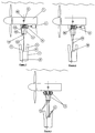
Figure 1 shows power generating equipment attached to a support structure by a tether; -
Figure 2 corresponds toFigure 1 but shows an alternative embodiment; -
Figure 3 corresponds to Figure'1 but shows a third embodiment; -
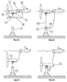
Figures 4a to 4d illustrate a method of deploying the power generating equipment ofFigure 1 ; and -
Figures 5a to 5d illustrate a method of retrieving the power generating equipment ofFigure 1 . - The power generating equipment shown in
Figure 1 comprises a buoyant power generating apparatus 1 (PGA). In this instance, thePGA 1 is a water current generating device; however, it is to be understood that the invention is equally applicable to any form of power generating apparatus. Also shown inFigure 1 is part of asupport structure 7, which is positioned on the bed of a body of water. Thesupport structure 7 comprises thefemale part 5 of an alignment means, while thePGA 1 comprises themale part 3 of the alignment means. It will be appreciated that the female and male parts of the alignment means could equally be positioned in the opposite orientation without affecting operation of the invention. - The term "alignment means" as used in this specification is intended to encompass any means by which the
PGA 1 andsupport structure 7 may be brought together in a defined alignment. For example, such alignment means may not have male and female parts as described herein, but two parts which mutually fit together in a predefined relationship. - The positive buoyancy of the
PGA 1 may either be inherent to thePGA 1 itself, or, if thePGA 1 is not inherently buoyant, buoyancy aids may be added to thePGA 1. - Positioned on the
male part 3 of the alignment means is anelectrical connector 11. Apower cable 13 runs from an electrical generator within thePGA 1 and terminates at theelectrical connector 11. A complementary electrical connector 6 is positioned in thefemale part 5 of the alignment means, with afurther power cable 8 running from the complementary electrical connector 6 to shore. In this way, when the PGA 1 andsupport structure 7 are brought together, as will be described in more detail below, the power generated by the PGA 1 may be supplied to shore. There may also exist certain other connections between the male andfemale parts - Also shown attached to the
PGA 1 is awinching device 4. Thewinching device 4 is powered by amotor drive 2. InFigure 1 , thewinching device 4 is shown permanently attached to thePGA 1, and themotor unit 2 is shown as being detachably connected to thewinching device 4. However, thewinching device 4 may be detachable from thePGA 1, and themotor unit 2 may be permanently attached to either thePGA 1 itself or thewinching device 4. An advantage of permanently attaching themotor unit 2 is that it reduces the number of operations that are required to deploy thePGA 1. However, advantages of detachably connecting themotor unit 2 are that only onemotor unit 2 may be required to deploy multiple PGAs, and themotor unit 2 will be easier to maintain. - A
tether 10 extends from thewinching device 4, throughguides 12 in thePGA 1, to atether connection 9 which is connected to thesupport structure 7. Thetether 10 can be any flexible length of line, rope, cable, chain, or similar means. - The centre of buoyancy A of the
PGA 1 is positioned in line with the central mating axis B of the alignment means 3, 5. Theguides 12 are also positioned in line with the central mating axis B of the alignment means 3, 5. This has the advantage that thePGA 1 will be lowered in a stable manner, ensuring that thePGA 1 remains suitably orientated in terms of pitch, roll and lateral position. - In the embodiment shown in
Figure 2 , thetether 10 is made up of two falls which pass through apulley block 14 mounted on thesupport structure 7. The end of thetether 10 is attached to ahard point 15 on the PGA. Further falls may be added if required. By using two or more falls, the mechanical advantage can be increased, allowing for a reduction in the power requirement of themotor unit 2. - In the embodiment shown in
Figure 3 , a pair of winchingdevices 4, each with arespective tether 10, guide 12 andtether connection 9, is used. Further winching devices may be used as necessary. The plurality of winching devices could each be powered by a corresponding plurality of motor units, or by a single motor unit via a connecting shaft or gearbox. By using more than one winching device, the stability and orientation control of the PGA could be improved during deployment. Further, extra winching devices provide extra power to pull the PGA down through the water column. -
Figure 4a shows the first step in deploying thePGA 1 ofFigure 1 on thesupport structure 7. ThePGA 1 is initially floating in a body of water, and is towed to the required position above thesupport structure 7 by asurface vessel 16. ThePGA 1 is connected to thevessel 16 by aline 17. - In this example, a
motor unit 2 is detachably connected to thewinching device 4, and linked with thesurface vessel 16 via a second line. This second line may be used to power or control themotor unit 2, or it may simply provide a means for retrieving themotor unit 2 after operation. - A remotely operated vehicle (ROV) 18 is used to take the
tether connection 9 down through the water column and attach it to the top of thesupport structure 7, whilst thewinching device 4 pays out the tether 10 (Figure 4b ). Divers, or any other suitable means, could also be used to perform this task. - In another embodiment of the invention, the
support structure 7 may comprise an automatic release buoy (not shown), which on activation deploys a separate tether to the surface for attachment to thewinching device 4. This has the advantage that aROV 18 or diver will not be required to attach thetether connection 9 to thesupport structure 7 itself. - At this stage, the
PGA 1 is cast off from thesurface vessel 16 by releasing theline 17. - The
motor unit 2 is then used to power thewinching device 4, thereby pulling thePGA 1 down through the water column towards the support structure 7 (Figure 4c ). -
Figure 4d shows thePGA 1 after it has mechanically mated with thesupport structure 7. Themale 3 and female 5 parts of the alignment means connect together, automatically aligning thePGA 1 in its correct orientation, and the two latch together so that thePGA 1 is retained on the support structure by the latched alignment means. In this example, the electrical connections 6, 11 (and fibre optic and hydraulic connections if there are any) are also made automatically upon mating of themale 3 and female 5 parts of the alignment means. This may be through the use of stab-plate type underwater mate connectors. Alternatively, electric, hydraulic, and/or fibre optic connections may be performed by divers or ROVs. - As shown in
Figure 4d , themotor unit 2 is detached from thewinching device 4 and retrieved by thesurface vessel 16. Because thePGA 1 is retained on thesupport structure 7 by the latched alignment means, thetether 10 is relieved of tension and so the removal of themotor unit 2 will not result in unwinding of thetether 10 from the winching device under the buoyancy of thePGA 1. - The subsequent retrieval of the
PGA 1 is achieved by the steps shown inFigures 5a to 5d . -
Figure 5a shows thePGA 1 attached to thesupport structure 7 as described above. A remotely operated vehicle (ROV) 18 is deployed from thesurface vessel 16 to release the latch holding thePGA 1 and thesupport structure 7 together. Alternatively, this action could be performed by a diver or other suitable means. -
Figure 5b shows the situation after the latch between thePGA 1 and thesupport structure 7 has been released. Under its own positive buoyancy, thePGA 1 rises towards the surface whilst thewinching device 4 pays out thetether 10. Thetether 10 remains connected to the support structure during this stage. However, themotor unit 2 may be used to power thewinching device 4 if necessary. Thetether connection 9 preferably remains attached to thesupport structure 7 during this stage, to avoid thePGA 1 rising uncontrollably under its own buoyancy. -
Figure 5c shows the situation when thePGA 1 has reached the surface. ThePGA 1 is made fast to thesurface vessel 16 by theline 17. - As shown in
Figure 5d , theROV 18 is then used to disconnect thetether connection 9 from thesupport structure 7. Again, a diver or other suitable means may be used to perform this task. Themotor unit 2 then powers thewinching device 4 to retract thetether 10. - Although some inspection or maintenance of the
PGA 1 may be performed while thePGA 1 floats above thesupport structure 7, it will be more usual for thePGA 1 to be towed by thevessel 16 to shore or to a suitably equipped ship for such maintenance. - The invention has the particular advantage that no large surface vessel with a heavy lift crane/winch is required to deploy the
PGA 1 onto thesupport structure 7, or subsequently to retrieve it. This obviates the need for heavy vessel lifting equipment and eliminates problems associated with the motion/heave of the vessel pulling in an unpredictable manner on the PGA. Consequently, it is possible to deploy or retrieve thePGA 1 in moderately severe weather conditions. - A further advantage is that no mechanical guide arrangement is required whilst lowering the PGA down through the water column, since the natural buoyancy of the PGA keeps the tether pulling in a predominantly vertical direction.
- A further advantage is that no seabed-mounted anchor/pulley block apparatus or complex tether connection devices are required.
- A further advantage is the accessible location of the winch and tether on the PGA where they can be serviced whenever the PGA is retrieved.
- A further advantage is that deployment or retrieval can be safely aborted at any time by releasing the tether from the support structure or cutting it, thus allowing the PGA to float freely to the surface and be recovered by a surface vessel.
Claims (16)
- Power generating equipment comprising:a buoyant power generating apparatus (1); anda support structure (7) for the power generating apparatus, which support structure (7), in use, is disposed on the bed of a body of water, and which support structure defines alignment and latching means (5) for the power generating apparatus,wherein the power generating apparatus (1) comprises:a generating unit having a centre of buoyancy positioned to maintain a stable pitch and roll attitude;alignment and latching means (3) adapted to align and latch the power generating apparatus with corresponding alignment and latching means (5) on the support structure (7), the alignment and latching means (3, 5) defining a central mating axis (B) when the power generating apparatus (1) is in engagement with the support structure (7); anda motor-driven winching device (4) having a flexible tether which is connectable at its free end to the support structure (7) whereby, in use, retraction of the tether (10) causes the power generating apparatus (1) to be drawn downwardly through the body of water into engagement with the support structure,characterised in that:the alignment and latching means (3) of the power generating apparatus (1) comprises guides (12) positioned such that a net buoyancy force acting on the generating unit is brought substantially into line with the central mating axis (B).
- Equipment as claimed in claim 1, wherein the alignment and latching means include electrical connectors or electrical connectors and one or more hydraulic and/or fibre optic connectors between the power generating apparatus and support structure.
- Equipment as claimed in claim 1 or 2, wherein a motor drive unit is detachably connected to the winching device.
- Equipment as claimed in claim 3, wherein the motor drive unit is mounted on or is part of a remotely operated vehicle.
- Equipment as claimed in claim 1 or 2, wherein a motor drive unit is built permanently into the winching device.
- Equipment as claimed in any one of the preceding claims, wherein a temporary buoyancy device is attached to the power generating apparatus.
- Equipment as claimed in any one of the preceding claims, wherein the tether has at least two falls at the support structure.
- Equipment as claimed in any one of the preceding claims, wherein the winching device comprises a plurality of winches and respective tethers.
- A method of deploying a submersible buoyant power generating apparatus (1) onto a support structure (7) submerged beneath a body of water, which support structure (7) defines alignment and latching means (5) for the power generating apparatus (1), the power generating apparatus (1) comprising a generating unit having a centre of buoyancy positioned to maintain a stable pitch and roll attitude, alignment and latching means (3) adapted to align and latch the power generating apparatus (1) with corresponding alignment and latching means on the support structure, the alignment and latching means (3, 5) defining a central mating axis (B), and a motor-driven winching device (4) having a flexible tether (10) which is connectable at its free end to the support structure (7) and which is retractable by the winching device (4), and the alignment and latching means (3) of the power generating apparatus (1) further comprises guides (12) positioned such that a net buoyancy force acting on the generating unit is brought substantially into line with the central mating axis (B), the method comprising:attaching a free end of the tether (10) to the submerged support structure (7), such that the power generating apparatus (1) is connected to the support structure (7) by only the flexible tether (10);operating the winching device (4) to winch the power generating apparatus (1) towards the submerged support structure (7);aligning the power generating apparatus (1) with the support structure (7) such that a net buoyancy force acting on the power generating apparatus (1) is brought substantially into line with the central mating axis (B); andlatching the power generating apparatus (1) to the support structure (7).
- A method as claimed in claim 9, further comprising:connecting electrical connectors or electrical connectors and one or more hydraulic and/or fibre optic connections between the power generating apparatus and support structure automatically at the same time as the latching of the power generating apparatus and support structure.
- A method as claimed in claim 9, further comprising:connecting electrical, hydraulic and fibre optic connections between the power generating apparatus and support structure by means of a diver or remotely operated vehicle after the latching of the power generating apparatus and support structure.
- A method as claimed in any one of claims 9 to 11, wherein the winching device is operated by a motor drive unit.
- A method as claimed in claim 12, wherein the motor drive unit is detached from the winching device after latching of the power generating apparatus to the support structure.
- A method as claimed in claim 12, wherein the motor drive unit remains connected to the winching device after latching of the power generating apparatus to the support structure.
- A method as claimed in any one of claims 9 to 12, wherein the winching device remains attached to the power generating apparatus after latching of the power generating apparatus to the support structure.
- A method as claimed in any one of claims 9 to 15, wherein the power generating apparatus is subsequently returned to the surface of the body of water by releasing the latching of the power generating apparatus to the support structure and allowing the power generating apparatus to rise while the tether is paid out by the winching device.
Applications Claiming Priority (2)
| Application Number | Priority Date | Filing Date | Title |
|---|---|---|---|
| GB0522133A GB2431628B (en) | 2005-10-31 | 2005-10-31 | A deployment and retrieval apparatus for submerged power generating devices |
| PCT/GB2006/003823 WO2007051968A1 (en) | 2005-10-31 | 2006-10-13 | Deployment apparatus for submerged power plant |
Publications (2)
| Publication Number | Publication Date |
|---|---|
| EP1945940A1 EP1945940A1 (en) | 2008-07-23 |
| EP1945940B1 true EP1945940B1 (en) | 2013-12-11 |
Family
ID=35516011
Family Applications (1)
| Application Number | Title | Priority Date | Filing Date |
|---|---|---|---|
| EP06794769.7A Active EP1945940B1 (en) | 2005-10-31 | 2006-10-13 | Deployment apparatus for submerged power plant |
Country Status (5)
| Country | Link |
|---|---|
| US (1) | US7859128B2 (en) |
| EP (1) | EP1945940B1 (en) |
| CA (1) | CA2627770C (en) |
| GB (1) | GB2431628B (en) |
| WO (1) | WO2007051968A1 (en) |
Families Citing this family (68)
| Publication number | Priority date | Publication date | Assignee | Title |
|---|---|---|---|---|
| CA2649828A1 (en) * | 2006-04-28 | 2007-11-08 | Swanturbines Limited | Tidal current turbine |
| EP1878911B1 (en) | 2006-07-14 | 2008-09-24 | OpenHydro Group Limited | Turbines having a debris release chute |
| EP1878913B1 (en) | 2006-07-14 | 2013-03-13 | OpenHydro Group Limited | Bi-directional tidal flow hydroelectric turbine |
| EP1879280B1 (en) | 2006-07-14 | 2014-03-05 | OpenHydro Group Limited | A hydroelectric turbine |
| ATE538304T1 (en) | 2006-07-14 | 2012-01-15 | Openhydro Group Ltd | UNDERWATER HYDROELECTRIC TURBINES WITH FLOATS |
| GB0704897D0 (en) * | 2007-03-14 | 2007-04-18 | Rotech Holdings Ltd | Power generator and turbine unit |
| EP1980746B2 (en) | 2007-04-11 | 2013-08-07 | OpenHydro Group Limited | A method of installing a hydroelectric turbine |
| GB2448710B (en) | 2007-04-24 | 2009-03-11 | Tidal Generation Ltd | A Mechanical connection system for submerged marine power generating devices |
| CA2706521A1 (en) * | 2007-11-23 | 2009-05-28 | Atlantis Resources Corporation Pte Limited | Control system for extracting power from water flow |
| US20090140524A1 (en) * | 2007-11-30 | 2009-06-04 | Kejha Joseph B | Deployable submarine-hydroelectric generator for sea currents energy harvesting |
| DE102007061185B4 (en) * | 2007-12-17 | 2010-11-11 | Voith Patent Gmbh | Diving power plant powered by a water flow |
| EP2088311B1 (en) | 2008-02-05 | 2015-10-14 | OpenHydro Group Limited | A hydroelectric turbine with floating rotor |
| CN102066667B (en) | 2008-04-14 | 2014-09-17 | 亚特兰蒂斯能源有限公司 | central axis hydraulic turbine |
| AU2009238206B2 (en) * | 2008-04-14 | 2013-03-14 | Atlantis Resources Corporation Pte Limited | Blade for a water turbine |
| EP2110910A1 (en) | 2008-04-17 | 2009-10-21 | OpenHydro Group Limited | An improved turbine installation method |
| DE102008020964B4 (en) * | 2008-04-25 | 2012-03-22 | Voith Patent Gmbh | Modular underwater power plant and method for its assembly |
| DE102008020965A1 (en) * | 2008-04-25 | 2009-10-29 | Voith Patent Gmbh | Apparatus and method for the installation and service of underwater power plants |
| GB0809334D0 (en) * | 2008-05-22 | 2008-07-02 | Scotrenewables Marine Power Lt | Generating apparatus |
| DE102008031615A1 (en) | 2008-07-07 | 2010-01-14 | Voith Patent Gmbh | Underwater power plant and method for its assembly |
| DE102008059891B4 (en) * | 2008-12-02 | 2010-10-07 | Voith Patent Gmbh | Underwater power plant with disconnectable nacelle |
| ATE556218T1 (en) | 2008-12-18 | 2012-05-15 | Openhydro Ip Ltd | HYDROELECTRIC TURBINE WITH PASSIVE BRAKE AND METHOD OF OPERATION |
| GB2466267A (en) * | 2008-12-18 | 2010-06-23 | Power Ltd C | Submerged electrical power generating apparatus and means for its deployment |
| EP2199199B1 (en) * | 2008-12-18 | 2011-12-07 | OpenHydro IP Limited | A hydroelectric turbine support system |
| DE602008002602D1 (en) | 2008-12-19 | 2010-10-28 | Openhydro Ip Ltd | Method for installing a hydroelectric turbine generator |
| ATE548562T1 (en) | 2009-04-17 | 2012-03-15 | Openhydro Ip Ltd | IMPROVED METHOD FOR CONTROLLING THE OUTPUT OF A HYDROELECTRIC TURBINE GENERATOR |
| KR20120042746A (en) | 2009-04-28 | 2012-05-03 | 아틀란티스 리소시스 코포레이션 피티이 리미티드 | Underwater power generator |
| FR2949826B1 (en) * | 2009-09-09 | 2012-01-20 | Electricite De France | HYDRAULIC TURBOMACHINE WITH SIMPLE MAINTENANCE |
| EP2302766B1 (en) | 2009-09-29 | 2013-03-13 | OpenHydro IP Limited | A hydroelectric turbine with coil cooling |
| EP2302755B1 (en) | 2009-09-29 | 2012-11-28 | OpenHydro IP Limited | An electrical power conversion system and method |
| EP2302204A1 (en) | 2009-09-29 | 2011-03-30 | OpenHydro IP Limited | A hydroelectric turbine system |
| US20110084490A1 (en) * | 2009-10-14 | 2011-04-14 | Vetco Gray Inc. | Electrical mudline system |
| AU2013204041B2 (en) * | 2009-10-27 | 2015-08-13 | Atlantis Resources Corporation Pte Limited | Underwater Power Generator |
| EP2494186A4 (en) * | 2009-10-27 | 2013-05-15 | Atlantis Resources Corp Pte | Underwater power generator |
| GB0921652D0 (en) | 2009-12-11 | 2010-01-27 | Rolls Royce Plc | Machine Buoyancy Control |
| DE102010033788A1 (en) * | 2010-08-09 | 2012-02-09 | Voith Patent Gmbh | Method and apparatus for installing a tented power plant |
| EP2450562B1 (en) | 2010-11-09 | 2015-06-24 | Openhydro IP Limited | A hydroelectric turbine recovery system and a method therefore |
| GB2486697B (en) | 2010-12-23 | 2013-05-29 | Tidal Generation Ltd | Power generating equipment |
| EP2469257B1 (en) | 2010-12-23 | 2014-02-26 | Openhydro IP Limited | A hydroelectric turbine testing method |
| NO20110329A1 (en) * | 2011-03-02 | 2012-07-23 | Hammerfest Stroem As | System for installation of a nacelle for an axial turbine on a submerged foundation, a nacelle, and a saddle for installation of the nacelle |
| JP5629035B2 (en) * | 2011-05-10 | 2014-11-19 | アトランティス リソーセズ コーポレーション ピーティーイー リミテッド | Deployment apparatus and method for deploying underwater power generation apparatus |
| DE102011112425B4 (en) | 2011-09-06 | 2013-04-11 | Voith Patent Gmbh | Installation vehicle for a tidal power plant and method for its operation |
| WO2013068008A1 (en) * | 2011-11-08 | 2013-05-16 | Pp Energy Aps | A female guiding device and a guiding assembly for guiding the connection of two rotor blade segments of a wind turbine |
| GB2497960B (en) * | 2011-12-23 | 2014-03-12 | Tidal Generation Ltd | Water current power generation installations |
| GB2497961B (en) | 2011-12-23 | 2014-03-12 | Tidal Generation Ltd | Water current power generation systems |
| GB2497962B (en) | 2011-12-23 | 2014-10-01 | Tidal Generation Ltd | Installing underwater structures |
| JP2013148031A (en) * | 2012-01-20 | 2013-08-01 | Kawasaki Heavy Ind Ltd | Water flow power generation facility |
| GB201201048D0 (en) * | 2012-01-23 | 2012-03-07 | Nova Innovation Ltd | An underwater turbine and method of installing an underwater turbine |
| KR20130092290A (en) * | 2012-02-10 | 2013-08-20 | 네이버비즈니스플랫폼 주식회사 | System and method for providing affiliate marketing service in integrated marketplace |
| GB2501249B (en) * | 2012-04-16 | 2014-08-06 | Tidal Generation Ltd | Water-based power generation installations |
| GB2504516A (en) * | 2012-08-01 | 2014-02-05 | Tidal Generation Ltd | A sub aquatic coupling for electrical connection hub |
| FR2997458B1 (en) * | 2012-10-30 | 2018-03-23 | Sabella | HYDROLIEN SYSTEM CONSISTING OF A CARRIER STRUCTURE, HAVING POSITIONING ELEMENTS EMITTING AND MEANS GUIDING THE EMBOITEMENT OF THE ELEMENTS |
| FR2997459B1 (en) * | 2012-10-30 | 2018-03-23 | Sabella | HYDROLIAN SYSTEM COMPRISING A TURBINE AND A CARRIER STRUCTURE, THE TURBINE HAVING AN ELECTRICAL SOCKET FOR COUPLING TO A CONNECTOR OF THE CARRIER STRUCTURE |
| GB2514849B (en) * | 2013-06-09 | 2015-12-23 | Tidal Generation Ltd | Power generating systems |
| GB2531947B (en) * | 2013-06-09 | 2016-12-14 | Tidal Generation Ltd | Power generating systems |
| GB2515011B (en) * | 2013-06-10 | 2015-06-10 | Tidal Generation Ltd | Power generating equipment |
| GB2515296B (en) | 2013-06-18 | 2015-06-17 | Tidal Generation Ltd | Power generating equipment |
| DE102013107122A1 (en) * | 2013-07-05 | 2015-01-08 | Smart Hydro Power Gmbh | Hydropower turbine for use in a flowing water |
| GB2520523B (en) * | 2013-11-22 | 2016-09-21 | Tidal Generation Ltd | Subsea cable engagement system |
| EP2887474A1 (en) * | 2013-12-20 | 2015-06-24 | Openhydro IP Limited | A method of managing a hydroelectric turbine array |
| FR3021366B1 (en) * | 2014-05-23 | 2017-12-08 | Cmi | HYDROLIEN SYSTEM COMPRISING A TURBINE AND A CARRIER STRUCTURE HAVING POSITIONING ELEMENTS EMITTING AND MEANS GUIDING THE EMBOITEMENT OF THE ELEMENTS |
| DE102014211040B3 (en) * | 2014-06-10 | 2015-07-23 | Voith Patent Gmbh | Underwater current power plant |
| GB2527540A (en) * | 2014-06-25 | 2015-12-30 | Tidal Generation Ltd | Power generating apparatus |
| JP5921647B1 (en) * | 2014-11-20 | 2016-05-24 | 有限会社板厚計測Bスコープ | Power generation equipment in the sea area that generates power using tidal currents or ocean currents |
| GB201503774D0 (en) * | 2015-03-05 | 2015-04-22 | Tidal Energy Ltd | Mounting for a tidal turbine |
| GB2550871B (en) * | 2016-05-26 | 2019-04-17 | Tidal Generation Ltd | Deploying submerged equipment |
| EP3339630A1 (en) * | 2016-12-21 | 2018-06-27 | Openhydro IP Limited | A method and system of deploying or recovering a hydroelectric turbine |
| KR102563957B1 (en) * | 2020-12-16 | 2023-08-04 | 엘아이지넥스원 주식회사 | Equipment detachable apparatus, equipment system with same, and equipment assembling and disassembling method |
| US20250002118A1 (en) * | 2023-06-30 | 2025-01-02 | Verterra Energy Inc. | Underwater anchoring devices, systems, and methods |
Family Cites Families (13)
| Publication number | Priority date | Publication date | Assignee | Title |
|---|---|---|---|---|
| DK102285C (en) * | 1962-11-30 | 1965-08-02 | Morten Lassen-Nielsen | Method for lowering large structures through deep water for laying on the bottom. |
| US4355511A (en) * | 1977-07-22 | 1982-10-26 | Dedger Jones | Wave energy conversion |
| US5774421A (en) * | 1997-08-04 | 1998-06-30 | The United States Of America As Represented By The Secretary Of The Navy | Underwater measurement device |
| NO322927B1 (en) * | 2001-02-13 | 2006-12-18 | Hammerfest Strom As | Device for the production of energy from streams in water bodies, an anchorage, and method of installation of the device |
| NO316980B1 (en) * | 2002-08-13 | 2004-07-12 | Hammerfest Strom As | Device for installing modules for a plant for the production of energy from streams in water bodies, an anchoring, as well as a method for installing the device. |
| GB0227739D0 (en) | 2002-11-28 | 2003-01-08 | Marine Current Turbines Ltd | Supporting structures for water current (including tidal stream) turbines |
| GB0306809D0 (en) * | 2003-03-25 | 2003-04-30 | Marine Current Turbines Ltd | Water current powered turbines installed on a deck or "false seabed" |
| GB0328732D0 (en) * | 2003-12-11 | 2004-01-14 | Uws Ventures Ltd | Water turbine |
| GB0329589D0 (en) * | 2003-12-20 | 2004-01-28 | Marine Current Turbines Ltd | Articulated false sea bed |
| BRPI0518599A2 (en) * | 2004-12-02 | 2008-11-25 | Wave Energy Technologies Inc | wave power device |
| GB0520891D0 (en) * | 2005-10-14 | 2005-11-23 | Tidal Generation Ltd | Foundation structure for water current energy system |
| US7489046B2 (en) * | 2006-06-08 | 2009-02-10 | Northern Power Systems, Inc. | Water turbine system and method of operation |
| GB0710822D0 (en) * | 2007-06-05 | 2007-07-18 | Overberg Ltd | Mooring system for tidal stream and ocean current turbines |
-
2005
- 2005-10-31 GB GB0522133A patent/GB2431628B/en not_active Expired - Fee Related
-
2006
- 2006-10-13 US US12/092,045 patent/US7859128B2/en active Active
- 2006-10-13 EP EP06794769.7A patent/EP1945940B1/en active Active
- 2006-10-13 CA CA2627770A patent/CA2627770C/en active Active
- 2006-10-13 WO PCT/GB2006/003823 patent/WO2007051968A1/en not_active Ceased
Also Published As
| Publication number | Publication date |
|---|---|
| US20090045631A1 (en) | 2009-02-19 |
| CA2627770A1 (en) | 2007-05-10 |
| GB2431628A (en) | 2007-05-02 |
| GB0522133D0 (en) | 2005-12-07 |
| GB2431628B (en) | 2009-01-28 |
| CA2627770C (en) | 2013-12-10 |
| US7859128B2 (en) | 2010-12-28 |
| WO2007051968A1 (en) | 2007-05-10 |
| EP1945940A1 (en) | 2008-07-23 |
Similar Documents
| Publication | Publication Date | Title |
|---|---|---|
| CA2627770C (en) | Deployment apparatus for submerged power plant | |
| CA2822405C (en) | Power generating equipment | |
| US7441988B2 (en) | Submerged power generating apparatus | |
| KR101741558B1 (en) | Method and device for installing a tidal power plant | |
| EP2110307B1 (en) | Mooring system | |
| EP2705247B1 (en) | Underwater turbine anchorage | |
| EP3008329B1 (en) | Power generating systems | |
| EP3008328B1 (en) | Power generating equipment | |
| JP2022003254A (en) | Marine power generation system | |
| DK181182B1 (en) | An offshore drilling vessel with an external cable connection and method therefor | |
| KR102020108B1 (en) | Tidal Current Power Generator Construction System With Easy Submarine Cable Installation | |
| GB2514773A (en) | Underwater turbine installation apparatus and methods | |
| GB2531947A (en) | Power generating systems |
Legal Events
| Date | Code | Title | Description |
|---|---|---|---|
| PUAI | Public reference made under article 153(3) epc to a published international application that has entered the european phase |
Free format text: ORIGINAL CODE: 0009012 |
|
| 17P | Request for examination filed |
Effective date: 20080602 |
|
| AK | Designated contracting states |
Kind code of ref document: A1 Designated state(s): AT BE BG CH CY CZ DE DK EE ES FI FR GB GR HU IE IS IT LI LT LU LV MC NL PL PT RO SE SI SK TR |
|
| RAP1 | Party data changed (applicant data changed or rights of an application transferred) |
Owner name: TIDAL GENERATION LIMITED |
|
| DAX | Request for extension of the european patent (deleted) | ||
| 17Q | First examination report despatched |
Effective date: 20120731 |
|
| GRAP | Despatch of communication of intention to grant a patent |
Free format text: ORIGINAL CODE: EPIDOSNIGR1 |
|
| INTG | Intention to grant announced |
Effective date: 20130809 |
|
| GRAS | Grant fee paid |
Free format text: ORIGINAL CODE: EPIDOSNIGR3 |
|
| GRAA | (expected) grant |
Free format text: ORIGINAL CODE: 0009210 |
|
| RAP1 | Party data changed (applicant data changed or rights of an application transferred) |
Owner name: TIDAL GENERATION LIMITED |
|
| AK | Designated contracting states |
Kind code of ref document: B1 Designated state(s): AT BE BG CH CY CZ DE DK EE ES FI FR GR HU IE IS IT LI LT LU LV MC NL PL PT RO SE SI SK TR |
|
| RBV | Designated contracting states (corrected) |
Designated state(s): AT BE BG CH CY CZ DE DK EE ES FI FR GR HU IE IS IT LI LT LU LV MC NL PL PT RO SE SI SK TR |
|
| REG | Reference to a national code |
Ref country code: CH Ref legal event code: EP |
|
| REG | Reference to a national code |
Ref country code: AT Ref legal event code: REF Ref document number: 644749 Country of ref document: AT Kind code of ref document: T Effective date: 20140115 |
|
| REG | Reference to a national code |
Ref country code: IE Ref legal event code: FG4D |
|
| REG | Reference to a national code |
Ref country code: DE Ref legal event code: R096 Ref document number: 602006039609 Country of ref document: DE Effective date: 20140206 |
|
| REG | Reference to a national code |
Ref country code: NL Ref legal event code: VDEP Effective date: 20131211 |
|
| REG | Reference to a national code |
Ref country code: AT Ref legal event code: MK05 Ref document number: 644749 Country of ref document: AT Kind code of ref document: T Effective date: 20131211 |
|
| PG25 | Lapsed in a contracting state [announced via postgrant information from national office to epo] |
Ref country code: LT Free format text: LAPSE BECAUSE OF FAILURE TO SUBMIT A TRANSLATION OF THE DESCRIPTION OR TO PAY THE FEE WITHIN THE PRESCRIBED TIME-LIMIT Effective date: 20131211 Ref country code: NL Free format text: LAPSE BECAUSE OF FAILURE TO SUBMIT A TRANSLATION OF THE DESCRIPTION OR TO PAY THE FEE WITHIN THE PRESCRIBED TIME-LIMIT Effective date: 20131211 Ref country code: SE Free format text: LAPSE BECAUSE OF FAILURE TO SUBMIT A TRANSLATION OF THE DESCRIPTION OR TO PAY THE FEE WITHIN THE PRESCRIBED TIME-LIMIT Effective date: 20131211 Ref country code: FI Free format text: LAPSE BECAUSE OF FAILURE TO SUBMIT A TRANSLATION OF THE DESCRIPTION OR TO PAY THE FEE WITHIN THE PRESCRIBED TIME-LIMIT Effective date: 20131211 |
|
| REG | Reference to a national code |
Ref country code: LT Ref legal event code: MG4D |
|
| PG25 | Lapsed in a contracting state [announced via postgrant information from national office to epo] |
Ref country code: CY Free format text: LAPSE BECAUSE OF FAILURE TO SUBMIT A TRANSLATION OF THE DESCRIPTION OR TO PAY THE FEE WITHIN THE PRESCRIBED TIME-LIMIT Effective date: 20131211 Ref country code: LV Free format text: LAPSE BECAUSE OF FAILURE TO SUBMIT A TRANSLATION OF THE DESCRIPTION OR TO PAY THE FEE WITHIN THE PRESCRIBED TIME-LIMIT Effective date: 20131211 Ref country code: AT Free format text: LAPSE BECAUSE OF FAILURE TO SUBMIT A TRANSLATION OF THE DESCRIPTION OR TO PAY THE FEE WITHIN THE PRESCRIBED TIME-LIMIT Effective date: 20131211 |
|
| PG25 | Lapsed in a contracting state [announced via postgrant information from national office to epo] |
Ref country code: IS Free format text: LAPSE BECAUSE OF FAILURE TO SUBMIT A TRANSLATION OF THE DESCRIPTION OR TO PAY THE FEE WITHIN THE PRESCRIBED TIME-LIMIT Effective date: 20140411 Ref country code: EE Free format text: LAPSE BECAUSE OF FAILURE TO SUBMIT A TRANSLATION OF THE DESCRIPTION OR TO PAY THE FEE WITHIN THE PRESCRIBED TIME-LIMIT Effective date: 20131211 Ref country code: BE Free format text: LAPSE BECAUSE OF FAILURE TO SUBMIT A TRANSLATION OF THE DESCRIPTION OR TO PAY THE FEE WITHIN THE PRESCRIBED TIME-LIMIT Effective date: 20131211 |
|
| PG25 | Lapsed in a contracting state [announced via postgrant information from national office to epo] |
Ref country code: ES Free format text: LAPSE BECAUSE OF FAILURE TO SUBMIT A TRANSLATION OF THE DESCRIPTION OR TO PAY THE FEE WITHIN THE PRESCRIBED TIME-LIMIT Effective date: 20131211 Ref country code: PL Free format text: LAPSE BECAUSE OF FAILURE TO SUBMIT A TRANSLATION OF THE DESCRIPTION OR TO PAY THE FEE WITHIN THE PRESCRIBED TIME-LIMIT Effective date: 20131211 Ref country code: PT Free format text: LAPSE BECAUSE OF FAILURE TO SUBMIT A TRANSLATION OF THE DESCRIPTION OR TO PAY THE FEE WITHIN THE PRESCRIBED TIME-LIMIT Effective date: 20140411 Ref country code: RO Free format text: LAPSE BECAUSE OF FAILURE TO SUBMIT A TRANSLATION OF THE DESCRIPTION OR TO PAY THE FEE WITHIN THE PRESCRIBED TIME-LIMIT Effective date: 20131211 Ref country code: SK Free format text: LAPSE BECAUSE OF FAILURE TO SUBMIT A TRANSLATION OF THE DESCRIPTION OR TO PAY THE FEE WITHIN THE PRESCRIBED TIME-LIMIT Effective date: 20131211 Ref country code: CZ Free format text: LAPSE BECAUSE OF FAILURE TO SUBMIT A TRANSLATION OF THE DESCRIPTION OR TO PAY THE FEE WITHIN THE PRESCRIBED TIME-LIMIT Effective date: 20131211 |
|
| REG | Reference to a national code |
Ref country code: DE Ref legal event code: R097 Ref document number: 602006039609 Country of ref document: DE |
|
| PLBE | No opposition filed within time limit |
Free format text: ORIGINAL CODE: 0009261 |
|
| STAA | Information on the status of an ep patent application or granted ep patent |
Free format text: STATUS: NO OPPOSITION FILED WITHIN TIME LIMIT |
|
| PG25 | Lapsed in a contracting state [announced via postgrant information from national office to epo] |
Ref country code: DK Free format text: LAPSE BECAUSE OF FAILURE TO SUBMIT A TRANSLATION OF THE DESCRIPTION OR TO PAY THE FEE WITHIN THE PRESCRIBED TIME-LIMIT Effective date: 20131211 |
|
| 26N | No opposition filed |
Effective date: 20140912 |
|
| REG | Reference to a national code |
Ref country code: DE Ref legal event code: R097 Ref document number: 602006039609 Country of ref document: DE Effective date: 20140912 |
|
| PG25 | Lapsed in a contracting state [announced via postgrant information from national office to epo] |
Ref country code: SI Free format text: LAPSE BECAUSE OF FAILURE TO SUBMIT A TRANSLATION OF THE DESCRIPTION OR TO PAY THE FEE WITHIN THE PRESCRIBED TIME-LIMIT Effective date: 20131211 |
|
| REG | Reference to a national code |
Ref country code: DE Ref legal event code: R119 Ref document number: 602006039609 Country of ref document: DE |
|
| PG25 | Lapsed in a contracting state [announced via postgrant information from national office to epo] |
Ref country code: MC Free format text: LAPSE BECAUSE OF FAILURE TO SUBMIT A TRANSLATION OF THE DESCRIPTION OR TO PAY THE FEE WITHIN THE PRESCRIBED TIME-LIMIT Effective date: 20131211 Ref country code: LU Free format text: LAPSE BECAUSE OF FAILURE TO SUBMIT A TRANSLATION OF THE DESCRIPTION OR TO PAY THE FEE WITHIN THE PRESCRIBED TIME-LIMIT Effective date: 20141013 |
|
| REG | Reference to a national code |
Ref country code: CH Ref legal event code: PL |
|
| REG | Reference to a national code |
Ref country code: IE Ref legal event code: MM4A |
|
| PG25 | Lapsed in a contracting state [announced via postgrant information from national office to epo] |
Ref country code: LI Free format text: LAPSE BECAUSE OF NON-PAYMENT OF DUE FEES Effective date: 20141031 Ref country code: DE Free format text: LAPSE BECAUSE OF NON-PAYMENT OF DUE FEES Effective date: 20150501 Ref country code: CH Free format text: LAPSE BECAUSE OF NON-PAYMENT OF DUE FEES Effective date: 20141031 |
|
| REG | Reference to a national code |
Ref country code: FR Ref legal event code: PLFP Year of fee payment: 10 |
|
| PG25 | Lapsed in a contracting state [announced via postgrant information from national office to epo] |
Ref country code: IE Free format text: LAPSE BECAUSE OF NON-PAYMENT OF DUE FEES Effective date: 20141013 |
|
| PG25 | Lapsed in a contracting state [announced via postgrant information from national office to epo] |
Ref country code: BG Free format text: LAPSE BECAUSE OF FAILURE TO SUBMIT A TRANSLATION OF THE DESCRIPTION OR TO PAY THE FEE WITHIN THE PRESCRIBED TIME-LIMIT Effective date: 20131211 |
|
| PG25 | Lapsed in a contracting state [announced via postgrant information from national office to epo] |
Ref country code: GR Free format text: LAPSE BECAUSE OF FAILURE TO SUBMIT A TRANSLATION OF THE DESCRIPTION OR TO PAY THE FEE WITHIN THE PRESCRIBED TIME-LIMIT Effective date: 20140312 Ref country code: IT Free format text: LAPSE BECAUSE OF FAILURE TO SUBMIT A TRANSLATION OF THE DESCRIPTION OR TO PAY THE FEE WITHIN THE PRESCRIBED TIME-LIMIT Effective date: 20131211 |
|
| PG25 | Lapsed in a contracting state [announced via postgrant information from national office to epo] |
Ref country code: HU Free format text: LAPSE BECAUSE OF FAILURE TO SUBMIT A TRANSLATION OF THE DESCRIPTION OR TO PAY THE FEE WITHIN THE PRESCRIBED TIME-LIMIT; INVALID AB INITIO Effective date: 20061013 |
|
| REG | Reference to a national code |
Ref country code: FR Ref legal event code: PLFP Year of fee payment: 11 |
|
| REG | Reference to a national code |
Ref country code: FR Ref legal event code: PLFP Year of fee payment: 12 |
|
| REG | Reference to a national code |
Ref country code: FR Ref legal event code: PLFP Year of fee payment: 13 |
|
| PGFP | Annual fee paid to national office [announced via postgrant information from national office to epo] |
Ref country code: TR Payment date: 20231004 Year of fee payment: 18 Ref country code: FR Payment date: 20231027 Year of fee payment: 18 |
|
| PG25 | Lapsed in a contracting state [announced via postgrant information from national office to epo] |
Ref country code: FR Free format text: LAPSE BECAUSE OF NON-PAYMENT OF DUE FEES Effective date: 20241031 |