EP1945334B1 - Efficient mbr operation in wastewater treatment - Google Patents
Efficient mbr operation in wastewater treatment Download PDFInfo
- Publication number
- EP1945334B1 EP1945334B1 EP20060827028 EP06827028A EP1945334B1 EP 1945334 B1 EP1945334 B1 EP 1945334B1 EP 20060827028 EP20060827028 EP 20060827028 EP 06827028 A EP06827028 A EP 06827028A EP 1945334 B1 EP1945334 B1 EP 1945334B1
- Authority
- EP
- European Patent Office
- Prior art keywords
- relaxation
- filtration
- air scour
- air
- valve
- Prior art date
- Legal status (The legal status is an assumption and is not a legal conclusion. Google has not performed a legal analysis and makes no representation as to the accuracy of the status listed.)
- Not-in-force
Links
- 238000004065 wastewater treatment Methods 0.000 title description 2
- 239000012528 membrane Substances 0.000 claims abstract description 38
- 238000001914 filtration Methods 0.000 claims abstract description 36
- 239000012466 permeate Substances 0.000 claims abstract description 27
- 239000010865 sewage Substances 0.000 claims abstract description 5
- 230000007423 decrease Effects 0.000 claims abstract description 3
- 238000000034 method Methods 0.000 claims description 32
- 230000001965 increasing effect Effects 0.000 claims description 8
- 230000003247 decreasing effect Effects 0.000 claims description 2
- 230000008569 process Effects 0.000 claims description 2
- XLYOFNOQVPJJNP-UHFFFAOYSA-N water Substances O XLYOFNOQVPJJNP-UHFFFAOYSA-N 0.000 claims description 2
- 239000007787 solid Substances 0.000 abstract description 9
- 239000007788 liquid Substances 0.000 abstract description 7
- 238000012554 master batch record Methods 0.000 abstract description 6
- 239000010802 sludge Substances 0.000 abstract description 3
- 230000007704 transition Effects 0.000 abstract 1
- 238000005273 aeration Methods 0.000 description 15
- 238000009991 scouring Methods 0.000 description 10
- 230000001351 cycling effect Effects 0.000 description 8
- 230000008901 benefit Effects 0.000 description 5
- 230000009467 reduction Effects 0.000 description 4
- 238000004140 cleaning Methods 0.000 description 3
- 230000004907 flux Effects 0.000 description 3
- 238000012423 maintenance Methods 0.000 description 3
- 238000000926 separation method Methods 0.000 description 3
- 230000000694 effects Effects 0.000 description 2
- 230000000717 retained effect Effects 0.000 description 2
- 238000011144 upstream manufacturing Methods 0.000 description 2
- 230000009471 action Effects 0.000 description 1
- 230000002708 enhancing effect Effects 0.000 description 1
- 230000005484 gravity Effects 0.000 description 1
- 230000000977 initiatory effect Effects 0.000 description 1
- 238000002955 isolation Methods 0.000 description 1
- 238000005457 optimization Methods 0.000 description 1
- 239000002245 particle Substances 0.000 description 1
- 230000002040 relaxant effect Effects 0.000 description 1
- 230000004044 response Effects 0.000 description 1
- 230000001932 seasonal effect Effects 0.000 description 1
- 239000002699 waste material Substances 0.000 description 1
- 239000002351 wastewater Substances 0.000 description 1
Images


Classifications
-
- B—PERFORMING OPERATIONS; TRANSPORTING
- B01—PHYSICAL OR CHEMICAL PROCESSES OR APPARATUS IN GENERAL
- B01D—SEPARATION
- B01D65/00—Accessories or auxiliary operations, in general, for separation processes or apparatus using semi-permeable membranes
- B01D65/02—Membrane cleaning or sterilisation ; Membrane regeneration
-
- B—PERFORMING OPERATIONS; TRANSPORTING
- B01—PHYSICAL OR CHEMICAL PROCESSES OR APPARATUS IN GENERAL
- B01D—SEPARATION
- B01D61/00—Processes of separation using semi-permeable membranes, e.g. dialysis, osmosis or ultrafiltration; Apparatus, accessories or auxiliary operations specially adapted therefor
- B01D61/14—Ultrafiltration; Microfiltration
- B01D61/22—Controlling or regulating
-
- B—PERFORMING OPERATIONS; TRANSPORTING
- B01—PHYSICAL OR CHEMICAL PROCESSES OR APPARATUS IN GENERAL
- B01D—SEPARATION
- B01D65/00—Accessories or auxiliary operations, in general, for separation processes or apparatus using semi-permeable membranes
- B01D65/08—Prevention of membrane fouling or of concentration polarisation
-
- C—CHEMISTRY; METALLURGY
- C02—TREATMENT OF WATER, WASTE WATER, SEWAGE, OR SLUDGE
- C02F—TREATMENT OF WATER, WASTE WATER, SEWAGE, OR SLUDGE
- C02F3/00—Biological treatment of water, waste water, or sewage
- C02F3/02—Aerobic processes
- C02F3/12—Activated sludge processes
- C02F3/1236—Particular type of activated sludge installations
- C02F3/1268—Membrane bioreactor systems
- C02F3/1273—Submerged membrane bioreactors
-
- B—PERFORMING OPERATIONS; TRANSPORTING
- B01—PHYSICAL OR CHEMICAL PROCESSES OR APPARATUS IN GENERAL
- B01D—SEPARATION
- B01D2313/00—Details relating to membrane modules or apparatus
- B01D2313/18—Specific valves
-
- B—PERFORMING OPERATIONS; TRANSPORTING
- B01—PHYSICAL OR CHEMICAL PROCESSES OR APPARATUS IN GENERAL
- B01D—SEPARATION
- B01D2313/00—Details relating to membrane modules or apparatus
- B01D2313/48—Mechanisms for switching between regular separation operations and washing
-
- B—PERFORMING OPERATIONS; TRANSPORTING
- B01—PHYSICAL OR CHEMICAL PROCESSES OR APPARATUS IN GENERAL
- B01D—SEPARATION
- B01D2315/00—Details relating to the membrane module operation
- B01D2315/06—Submerged-type; Immersion type
-
- B—PERFORMING OPERATIONS; TRANSPORTING
- B01—PHYSICAL OR CHEMICAL PROCESSES OR APPARATUS IN GENERAL
- B01D—SEPARATION
- B01D2321/00—Details relating to membrane cleaning, regeneration, sterilization or to the prevention of fouling
- B01D2321/18—Use of gases
- B01D2321/185—Aeration
-
- Y—GENERAL TAGGING OF NEW TECHNOLOGICAL DEVELOPMENTS; GENERAL TAGGING OF CROSS-SECTIONAL TECHNOLOGIES SPANNING OVER SEVERAL SECTIONS OF THE IPC; TECHNICAL SUBJECTS COVERED BY FORMER USPC CROSS-REFERENCE ART COLLECTIONS [XRACs] AND DIGESTS
- Y02—TECHNOLOGIES OR APPLICATIONS FOR MITIGATION OR ADAPTATION AGAINST CLIMATE CHANGE
- Y02W—CLIMATE CHANGE MITIGATION TECHNOLOGIES RELATED TO WASTEWATER TREATMENT OR WASTE MANAGEMENT
- Y02W10/00—Technologies for wastewater treatment
- Y02W10/10—Biological treatment of water, waste water, or sewage
Definitions
- This invention involves enhancement of a process already known and used in the sewage treatment industry. More specifically the enhancement relates to efficient operation of membrane separators which are increasingly used in sewage treatment plants for dewatering and concentration of sludge.
- Membrane separators are used in an increasing number of sewage treatment facilities because of their compactness and efficiency in removing a nearly-pure permeate from sludge or mixed liquor.
- the membrane separators require maintenance. They become partially clogged by accumulated solids separated out by the micropore filters of the membranes; air scouring, constant or intermittent, typically is used to agitate and loosen the accumulated solids from the surfaces of the membranes.
- relaxation improves the overall hydraulic performance of membranes submerged in mixed liquor.
- simple terms relaxation is generally described as a procedure whereby filtration is suspended for a time but air scouring (cleaning) is continued. Relaxation removes solids that have accumulated at the membrane surface during filtration (dewatering).
- relaxation frequencies and duration are on the order of hours or minutes.
- the primary limitation is the effective derating of a plant that occurs as membranes are taken out of service more frequently or for longer periods of time to increase the benefits of relaxation.
- Typical membrane bioreactor (MBR) wastewater treatment plants are designed to handle daily (diurnal) and seasonal variation in both hydraulic and waste loading. However, for design and operational purposes, such variations must fall within pre-defined limits and average daily flow rate (ADF) over each 24-hour cycle of operation further limited to minimize maintenance requirements and extend membrane service life.
- ADF average daily flow rate
- Air scour in MBR-basins is at a constant rate through the filtration and relaxation cycle, although in some cases air may have been cycled on and off during the filtration.
- US 6325928-B and WO-00/21890-A discloses methods using enhanced aeration during relaxation periods. It is an object of the invention to greatly improve efficiency of operation of membrane separators, by controlling the scouring air flow rate and optionally enhancing the removal of accumulated solids from the membranes during relaxation, all of which reduces cost of operation and can also reduce capital cost.
- air scour requirements are decreased through the use of proportional aeration.
- Air-scouring rates can be varied proportionally to match the permeate (filtrated water) flow rate.
- Current practice calls for constant aeration at any permeate flow rate and or what is referred to as air cycling.
- Air cycling is a patented method whereby valves are used to alternately feed the same air between two membranes units or cassettes operating in parallel. Air cycling subjects membranes to intense air scouring followed by equal periods of non-aeration.
- proportional aeration filtration must be accompanied by some amount of aeration and the method of apportioning that aeration is not limited to a given apparatus.
- Proportional aeration simply follows the particular need for flow rate of air scour based on the conditions of flux and loading against the MBRs. Air flow is not wasted when not needed. In contrast, current practice has been simply to keep air scour flow rate constant, without variation during filtration (except, as noted above, that the air has sometimes been switched on and off during filtration).
- filtration/relaxation cycles are much more frequent, and can be on the order of seconds rather than minutes. This can improve the benefits of relaxation without further derating plant performance if relative filtration/relaxation times are kept approximately constant.
- a typical relaxation cycle (1 min. relax/9 min. filtration) effectively derates a plant by 10%. Relaxing for 10 seconds every 100 seconds should increase sustainable flow rate by removing accumulated solids more frequently and preventing buildup at the membrane surface.
- FCVs permeate flow control valves
- FCVs electrically actuated permeate flow control valves
- FCVs generally have a throw time of 30 to 60 seconds. This means it takes up to 60 seconds for the valve to fully open or fully close from the opposite condition.
- Such a throw time limits how frequent relaxation can occur because time spent opening after each cycle further reduces plant throughput.
- overshoot a phenomenon called overshoot can occur. During overshoot, the valve opens too far allowing filtration rates temporarily to spike. Spikes in filtration bring large amounts of solids to the membranes surface effectively undoing the benefits of relaxation. Constant opening and closing of valves during frequent relaxation also increases wear causing valves to fail and operating costs to increase.
- the first method involves adding a second, pneumatically actuated valve upstream of the FCV.
- the pneumatically operated valve opens and closes during relax while the FCV stays in the same position.
- Pneumatic valve throw times are on the order of 6-15 seconds. In this configuration, the FCV does not close during relaxation and overshoot is reduced after each relax cycle.
- the second method and configuration is generally more cost effective and easier to operate. Similar to the method proposed above, inexpensive quarter turn valves (butterfly, ball, plug) are installed upstream of each FCV and operated using a camshaft connected to a motor. As the motor turns at an adjustable frequency, the cams open and close these isolation valves while the FCV stays in position to limit overshoot following each relax cycle. This method improves controllability and eliminates the need for actuators that can wear.
- Another aspect of the invention is to enhance efficiency in MBR operation through enhanced relaxation.
- air scour rates are reduced, but are at much higher flow rate during relaxation.
- the overall air scour flow is reduced.
- membranes are relaxed one minute every ten minutes to remove solids that have accumulated at the membrane surface.
- the air scour requirement would be reduced from 25%-50% during the nine-minute filtration cycle and increased to 100% or more of nominal flow for the one-minute relaxation cycle.
- the net decrease in aeration requirement would be approximately 22.5% assuming a 25% reduction in air during filtration.
- the actual benefit could be more depending on actual operating conditions.
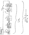
- Figure 1 schematically shows two different aspects of the invention if combined with the method according to claim 1. These are enhanced relaxation, in which air scour rate is lowered during normal filtration/membrane separation and set at a higher rate during relaxation; and, in a second aspect, wherein the cycle of filtration and relaxation is greatly shortened, with relaxation occurring at a much higher frequency.
- the block 10 indicates ongoing filtration, i.e. membrane separation, occurring at a low level of air scour.
- a flow modulation valve is schematically indicated at 12, representing prior art flow control valves which preferably retained pursuant to the invention.
- the block 14 indicates initiation of a membrane relaxation cycle.
- the following block 16 denotes closing of an in-line valve, a valve additional to the flow control 12, in the liquid line, located preferably downstream of the MBRs and thus shutting off flow of effluent permeate. As indicated, this valve can be pneumatically or mechanically controlled. At the same time, the air scour rate is significantly raised, as noted in the block 18. The scour rate can be raised by about thirty percent, fifty percent, or even about one hundred percent.
- a break 20 shown in the time line between the block 18 and the following block 22 represents the duration of time the high air scour is on and the inline valve is actually closed.
- air scour is switched back to the low level and the inline valve is opened to resume MBR separation. After the prescribed filtration time, the system goes back to the relax cycle, as indicated at 26.
- the total cycle of filtration/relaxation can be, for example, about ten seconds to several minutes, e.g. five minutes.
- the relaxation portion of the cycle can be, for example, about one second to about one minute, more preferably about one second to about ten seconds for short cycling.
- Total cycle times can be about 10 to 30 seconds, with about one to five seconds relaxation; or, for very short cycling, total cycle time of about 10 seconds, with about one second relaxation. This is about one or more orders of magnitude more frequent cycling than in the prior art, where the full cycle was typically measured in hours, and more recently, the assignee of this invention initiated shorter cycles of about ten minutes, about one minute of which was the relaxation cycle.
- Figure 2 shows the invention : proportional air scouring.
- a plot of permeate flow ratio and of air scour rate against time the thin line 30 indicates permeate flow.
- the flow rate is expressed as a ratio, with 1.0 representing average daily flow or ADF.
- the X axis or horizontal axis is in hours, showing over one day's time, and indicating diurnal variations in permeate flow due to variations in influent wastewater to the MBR tanks.
- hourly flow rates can range from half the ADF up to twice the ADF design value.
- Air scour is shown in the hourly bars 32. The bars in the graph show a pattern pursuant to the invention.
- a normal, prior air scour rate is at the value 1.0 on the vertical axis, shown on the scale at the right side. This would be the air scour rate used constantly, regardless of diurnal variations, according to prior practice. However, by varying the air scour rate in accordance with diurnal changes in flow, the total amount of air delivered to the system, in the example shown in the graph, can be about nineteen percent less than the amount delivered under common prior practice.
- the bars 32 show that air scour rate can be about seventy-five percent of nominal rate (i.e. of the 1.0 rate) when diurnal flow is down to about fifty percent and when it is up to ADF value.
- the air scour rate is increased greatly, in this example to the nominal 1.0 ratio (note that 1.0 could represent any base air scour value desired).
- the graph also shows that when the diurnal flow increase is over, the system responds by lowering the air ratio back to about seventy-five percent of nominal value, in this example.
- Figure 3 shows the enhanced MBR relax method not in accordance with the invention in graph form.
- This graph plots permeate flow ratio, as well as air scour ratio, against time in minutes.
- the flow ratio scale is on the left side vertical axis, while the air scour ratio is on the right side vertical axis. This can be combined with the higher frequency cycling which is shown in Figure 1 and discussed above.
- the bars 35 in the graph represent air scour ratio as compared to a nominal air scour flow rate of 1.0, as in the previous graph. A bar is shown for each minute of time.
- the solid line 36 is a plot of permeate flow ratio (as in the previous graph), as compared to a nominal 1.0 during the period of time covered by the graph.
- Figure 3 shows one example, and in this example relaxation occurs one minute out of every ten minutes in a cycle, as indicated by the line plot 36.
- this method adjusts air scour ratio to lower the rate or ratio considerably during normal filtration.
- air scour ratio is lowered to about seventy percent of nominal during normal filtration.
- the long bars 35 that occur in one minute out of every ten show increase of air scour, to the 1.0 ratio, i.e. nominal flow rate.
- air scour flow is increased by about thirty-three percent in this example for the relaxation, where scouring caked particles off the membrane is most important.
- the air scour flow rate at relaxation might be as much as twice the air flow rate during filtration, or even more if desired. As discussed above, this method can greatly increase the efficiency of the MBR system, achieving better cleaning during relaxation and, again, saving on air scour and blower operation costs.
- Figure 4 shows a combined method or system in accordance with the invention wherein the effects of Figures 2 and 3 are combined in a single graph.
- the line plotting 40 shows the permeate ratio, with diurnal changes just as shown in Figure 2 , over a period of about one day.
- the air scour ratio is greatly reduced by combining the effects of the two methods.
- Figure 4 indicates the expected efficiency of such combined system, which significantly improves the energy efficiency of any MBR system utilizing submerged membranes.
- FIGS 5 and 6 show one example of a valve arrangement useful for the system and method of aspects of the invention. These views show a permeate effluent pipe 50 downstream of the membrane separators in the system.
- a flow control valve (FCV) is shown in the line at 52, typical of prior art systems for modulating the flow rate of permeate and thus the rate at which the liquid passes through the membrane separators.
- FCV flow control valve
- the liquid flows through the membranes under pump or gravity pressure, and the flow control valve 52 modulates flow in accordance with system operating parameters.
- an additional valve 54 is put in the line.
- this valve is a simple gate valve shutoff, and can be a quarter-turn valve such a ball valve (with a hole that is either in line with the flow or at ninety degrees to the flow) or a glove valve or a butterfly-type valve, i.e. a plate that rotates to block flow or to be aligned with flow.
- the actual valve closure member is not shown, but the drawings indicate a worm gear arrangement at 56, by which rotation of a shaft 58, through the worm gear arrangement, rotates a shaft that is shown vertical in this particular orientation of the valve (the orientation could be otherwise), along a rotational axis 60.
- the valve stem operates to close or open the ball valve globe valve, butterfly valve or other appropriate type of in line gate valve.
- a motor 62 which may be geared down internally as needed, has a sprocket 64 engaged with a chain 66 that rotates another sprocket 68 when the valve has to be opened or closed.
- the sprocket 68 is connected to the worm gear shaft 58 discussed above.
- the sprockets 64 and 68 can be sized appropriately to achieve the desired speed of valve opening and closing.
- the motor 62 preferably has variable frequency drive (VFD) responsive to a variable current control signal. For example, an appropriate duration for opening or closing the valve, would be about one second. This could be appropriate for a one second relaxation period, although faster opening/closing times could be used, or longer duration opening/closing especially for a longer relax period. Often field optimization will determine relax frequency and duration as well as valve cycle time.
- a separate valve 54 which could have another type of actuation, such as a pneumatically-driven valve
- the function of the existing FCV 52 is not affected, and flow settings in the FCV are retained during periods of relaxation.
- the overshoot problem discussed above can be avoided by use of this separate valve because the separate valve need not reach a control set point when re-opened and the FCV will need little or no movement to reach the control point. Reducing overshoot reduces the frequency of needed maintenance cleaning, thereby increasing life of the membranes.
- the same controller used for the permeate valve 54 can be used to increase air rate for relaxation when the permeate valve is closed and vice versa. If pneumatic control is used, common control can be used for air and permeate flow switching regardless of pipe line locations.
Landscapes
- Chemical & Material Sciences (AREA)
- Chemical Kinetics & Catalysis (AREA)
- Engineering & Computer Science (AREA)
- Water Supply & Treatment (AREA)
- Life Sciences & Earth Sciences (AREA)
- Microbiology (AREA)
- Biodiversity & Conservation Biology (AREA)
- Hydrology & Water Resources (AREA)
- Environmental & Geological Engineering (AREA)
- Organic Chemistry (AREA)
- Separation Using Semi-Permeable Membranes (AREA)
- Separation Of Suspended Particles By Flocculating Agents (AREA)
- Activated Sludge Processes (AREA)
- Physical Water Treatments (AREA)
Abstract
Description
- This invention involves enhancement of a process already known and used in the sewage treatment industry. More specifically the enhancement relates to efficient operation of membrane separators which are increasingly used in sewage treatment plants for dewatering and concentration of sludge.
- Membrane separators, often called membrane bioreactors or MBRs, are used in an increasing number of sewage treatment facilities because of their compactness and efficiency in removing a nearly-pure permeate from sludge or mixed liquor. The membrane separators require maintenance. They become partially clogged by accumulated solids separated out by the micropore filters of the membranes; air scouring, constant or intermittent, typically is used to agitate and loosen the accumulated solids from the surfaces of the membranes.
- It is known that a procedure called relaxation improves the overall hydraulic performance of membranes submerged in mixed liquor. In simple terms relaxation is generally described as a procedure whereby filtration is suspended for a time but air scouring (cleaning) is continued. Relaxation removes solids that have accumulated at the membrane surface during filtration (dewatering).
- In the literature, relaxation frequencies and duration are on the order of hours or minutes. The primary limitation is the effective derating of a plant that occurs as membranes are taken out of service more frequently or for longer periods of time to increase the benefits of relaxation.
- Typical membrane bioreactor (MBR) wastewater treatment plants are designed to handle daily (diurnal) and seasonal variation in both hydraulic and waste loading. However, for design and operational purposes, such variations must fall within pre-defined limits and average daily flow rate (ADF) over each 24-hour cycle of operation further limited to minimize maintenance requirements and extend membrane service life.
- Air scour in MBR-basins, as typically practiced in MBR basins using relaxation, is at a constant rate through the filtration and relaxation cycle, although in some cases air may have been cycled on and off during the filtration.
-
US 6325928-B andWO-00/21890-A - In another aspect of the invention, air scour requirements are decreased through the use of proportional aeration. Air-scouring rates can be varied proportionally to match the permeate (filtrated water) flow rate. Current practice calls for constant aeration at any permeate flow rate and or what is referred to as air cycling. Air cycling is a patented method whereby valves are used to alternately feed the same air between two membranes units or cassettes operating in parallel. Air cycling subjects membranes to intense air scouring followed by equal periods of non-aeration. Using proportional aeration, filtration must be accompanied by some amount of aeration and the method of apportioning that aeration is not limited to a given apparatus.
- Although aeration requirements are a function of numerous factors including equipment geometry and membrane properties, general practice requires operation at some minimum value, constant value. Below are quantifiable guidelines for establishing aeration requirements as a function of ADF:
- At or below 150% ADF, aeration can be reduced to 75% of what is now considered the minimum requirement.
- At fluxes above 150% ADF and up to 220% ADF, aeration should be increased to 100% of the current minimum requirement.
- At fluxes above 220% ADF, aeration should be increase up to 150% of the current minimum requirement.
- Proportional aeration simply follows the particular need for flow rate of air scour based on the conditions of flux and loading against the MBRs. Air flow is not wasted when not needed. In contrast, current practice has been simply to keep air scour flow rate constant, without variation during filtration (except, as noted above, that the air has sometimes been switched on and off during filtration).
- Pursuant to an aspect of this invention, filtration/relaxation cycles are much more frequent, and can be on the order of seconds rather than minutes. This can improve the benefits of relaxation without further derating plant performance if relative filtration/relaxation times are kept approximately constant. For example, a typical relaxation cycle (1 min. relax/9 min. filtration) effectively derates a plant by 10%. Relaxing for 10 seconds every 100 seconds should increase sustainable flow rate by removing accumulated solids more frequently and preventing buildup at the membrane surface.
- Perceived limitations on the frequency of relaxation are controllability and valve wear. Controllability refers to the time it takes a valve to open or a pump to turn on and what happens to the flow after such action occurs. For example, electrically actuated permeate flow control valves (FCVs) generally have a throw time of 30 to 60 seconds. This means it takes up to 60 seconds for the valve to fully open or fully close from the opposite condition. Such a throw time limits how frequent relaxation can occur because time spent opening after each cycle further reduces plant throughput. In addition, if an FCV opens too fast, a phenomenon called overshoot can occur. During overshoot, the valve opens too far allowing filtration rates temporarily to spike. Spikes in filtration bring large amounts of solids to the membranes surface effectively undoing the benefits of relaxation. Constant opening and closing of valves during frequent relaxation also increases wear causing valves to fail and operating costs to increase.
- This aspect of the invention encompasses two methods to address the concerns of controllability and wear. The first method involves adding a second, pneumatically actuated valve upstream of the FCV. The pneumatically operated valve opens and closes during relax while the FCV stays in the same position. Pneumatic valve throw times are on the order of 6-15 seconds. In this configuration, the FCV does not close during relaxation and overshoot is reduced after each relax cycle.
- The second method and configuration is generally more cost effective and easier to operate. Similar to the method proposed above, inexpensive quarter turn valves (butterfly, ball, plug) are installed upstream of each FCV and operated using a camshaft connected to a motor. As the motor turns at an adjustable frequency, the cams open and close these isolation valves while the FCV stays in position to limit overshoot following each relax cycle. This method improves controllability and eliminates the need for actuators that can wear.
- The drastic reduction in cycle lengths, i.e. the much more frequent relaxation of the membranes from filtration, while retaining a roughly similar ratio between total filtration time and total relaxation time, tends to remove accumulated solids from membrane surfaces in an overall more efficient scheme, not allowing clogging to proceed as far as with the typical longer relaxation cycling used previously, with the result that overall air requirements for a given permeate flow rate can be reduced, or, on the other hand, a greater flow rate can be achieved from a given total surface area of membrane separators.
- Another aspect of the invention is to enhance efficiency in MBR operation through enhanced relaxation. During filtration air scour rates are reduced, but are at much higher flow rate during relaxation. The overall air scour flow is reduced. Typically, membranes are relaxed one minute every ten minutes to remove solids that have accumulated at the membrane surface. Using the proposed innovation, the air scour requirement would be reduced from 25%-50% during the nine-minute filtration cycle and increased to 100% or more of nominal flow for the one-minute relaxation cycle. The net decrease in aeration requirement would be approximately 22.5% assuming a 25% reduction in air during filtration. The actual benefit could be more depending on actual operating conditions.
- It is therefore among the objects of the invention to improve efficiency in membrane separator operation achieving savings in overall air scour requirements and more efficient operation of the MBRs. These and other objects, advantages and features of the invention will be apparent from the following description of preferred embodiments, considered along with the accompanying drawings.
-
-
Figure 1 is a simple flow chart illustrating several aspects of the invention. -
Figure 2 is a graph showing permeate flow as well as air scour as a function of time, illustrating the proportional air scouring method of the invention. -
Figure 3 is a graph showing permeate flow and also air scour versus time, to illustrate an enhanced relaxation method for MBRs not in accordance with the invention. -
Figure 4 is another graph showing permeate flow and air scour flow versus time, and illustrating a method with both proportional air scouring according to the invention and enhanced relaxation. -
Figure 5 is a perspective view schematically showing a permeate effluent pipeline at an MBR system useful in certain aspects of the invention, with two different valves in series, one being a flow modulation valve to control the rate of flow and the other being a relaxation valve to shut off flow periodically for MBR relaxation. -
Figure 6 is an enlarged view showing a portion of the apparatus inFigure 5 . - In the drawings,
Figure 1 schematically shows two different aspects of the invention if combined with the method according toclaim 1. These are enhanced relaxation, in which air scour rate is lowered during normal filtration/membrane separation and set at a higher rate during relaxation; and, in a second aspect, wherein the cycle of filtration and relaxation is greatly shortened, with relaxation occurring at a much higher frequency. InFigure 1 theblock 10 indicates ongoing filtration, i.e. membrane separation, occurring at a low level of air scour. A flow modulation valve is schematically indicated at 12, representing prior art flow control valves which preferably retained pursuant to the invention. - The block 14 indicates initiation of a membrane relaxation cycle. The following block 16 denotes closing of an in-line valve, a valve additional to the
flow control 12, in the liquid line, located preferably downstream of the MBRs and thus shutting off flow of effluent permeate. As indicated, this valve can be pneumatically or mechanically controlled. At the same time, the air scour rate is significantly raised, as noted in theblock 18. The scour rate can be raised by about thirty percent, fifty percent, or even about one hundred percent. - A
break 20 shown in the time line between theblock 18 and the followingblock 22 represents the duration of time the high air scour is on and the inline valve is actually closed. - At 22 and 24, air scour is switched back to the low level and the inline valve is opened to resume MBR separation. After the prescribed filtration time, the system goes back to the relax cycle, as indicated at 26.
- The drawing indicates that the total cycle of filtration/relaxation can be, for example, about ten seconds to several minutes, e.g. five minutes. The relaxation portion of the cycle can be, for example, about one second to about one minute, more preferably about one second to about ten seconds for short cycling. Total cycle times can be about 10 to 30 seconds, with about one to five seconds relaxation; or, for very short cycling, total cycle time of about 10 seconds, with about one second relaxation. This is about one or more orders of magnitude more frequent cycling than in the prior art, where the full cycle was typically measured in hours, and more recently, the assignee of this invention initiated shorter cycles of about ten minutes, about one minute of which was the relaxation cycle.
-
Figure 2 shows the invention : proportional air scouring. In the graph ofFigure 2 , a plot of permeate flow ratio and of air scour rate against time, thethin line 30 indicates permeate flow. In this graph the flow rate is expressed as a ratio, with 1.0 representing average daily flow or ADF. The X axis or horizontal axis is in hours, showing over one day's time, and indicating diurnal variations in permeate flow due to variations in influent wastewater to the MBR tanks. As the graph indicates, hourly flow rates can range from half the ADF up to twice the ADF design value. Air scour is shown in the hourly bars 32. The bars in the graph show a pattern pursuant to the invention. A normal, prior air scour rate is at the value 1.0 on the vertical axis, shown on the scale at the right side. This would be the air scour rate used constantly, regardless of diurnal variations, according to prior practice. However, by varying the air scour rate in accordance with diurnal changes in flow, the total amount of air delivered to the system, in the example shown in the graph, can be about nineteen percent less than the amount delivered under common prior practice. Thebars 32 show that air scour rate can be about seventy-five percent of nominal rate (i.e. of the 1.0 rate) when diurnal flow is down to about fifty percent and when it is up to ADF value. In response to the permeate flow increasing, such as the doubling shown in thegraph line 30, the air scour rate is increased greatly, in this example to the nominal 1.0 ratio (note that 1.0 could represent any base air scour value desired). The graph also shows that when the diurnal flow increase is over, the system responds by lowering the air ratio back to about seventy-five percent of nominal value, in this example. - Assuming a constant pressure on the blower that provides aeration, a nineteen percent reduction in volumetric flow rate equates to the same reduction in power costs.
-
Figure 3 shows the enhanced MBR relax method not in accordance with the invention in graph form. This graph plots permeate flow ratio, as well as air scour ratio, against time in minutes. The flow ratio scale is on the left side vertical axis, while the air scour ratio is on the right side vertical axis. This can be combined with the higher frequency cycling which is shown inFigure 1 and discussed above. - In
Figure 3 thebars 35 in the graph represent air scour ratio as compared to a nominal air scour flow rate of 1.0, as in the previous graph. A bar is shown for each minute of time. Thesolid line 36 is a plot of permeate flow ratio (as in the previous graph), as compared to a nominal 1.0 during the period of time covered by the graph. -
Figure 3 shows one example, and in this example relaxation occurs one minute out of every ten minutes in a cycle, as indicated by theline plot 36. Instead of keeping air scour at a constant flow rate through a cycle of filtration/permeation and relaxation, this method adjusts air scour ratio to lower the rate or ratio considerably during normal filtration. In the example air scour ratio is lowered to about seventy percent of nominal during normal filtration. Thelong bars 35 that occur in one minute out of every ten show increase of air scour, to the 1.0 ratio, i.e. nominal flow rate. Thus, air scour flow is increased by about thirty-three percent in this example for the relaxation, where scouring caked particles off the membrane is most important. - These numbers are only examples. The air scour flow rate at relaxation might be as much as twice the air flow rate during filtration, or even more if desired. As discussed above, this method can greatly increase the efficiency of the MBR system, achieving better cleaning during relaxation and, again, saving on air scour and blower operation costs.
-
Figure 4 shows a combined method or system in accordance with the invention wherein the effects ofFigures 2 and3 are combined in a single graph. With the proportional air scouring responding to diurnal liquid flow changes, combined with the enhanced relax methods just discussed, the efficiency of the system can be even further improved. Here, the line plotting 40 shows the permeate ratio, with diurnal changes just as shown inFigure 2 , over a period of about one day. However, the air scour ratio is greatly reduced by combining the effects of the two methods.Figure 4 indicates the expected efficiency of such combined system, which significantly improves the energy efficiency of any MBR system utilizing submerged membranes. -
Figures 5 and6 show one example of a valve arrangement useful for the system and method of aspects of the invention. These views show apermeate effluent pipe 50 downstream of the membrane separators in the system. A flow control valve (FCV) is shown in the line at 52, typical of prior art systems for modulating the flow rate of permeate and thus the rate at which the liquid passes through the membrane separators. The liquid flows through the membranes under pump or gravity pressure, and theflow control valve 52 modulates flow in accordance with system operating parameters. - As shown in
Figures 5 and6 , an additional valve 54 is put in the line. As noted above, this valve is a simple gate valve shutoff, and can be a quarter-turn valve such a ball valve (with a hole that is either in line with the flow or at ninety degrees to the flow) or a glove valve or a butterfly-type valve, i.e. a plate that rotates to block flow or to be aligned with flow. The actual valve closure member is not shown, but the drawings indicate a worm gear arrangement at 56, by which rotation of ashaft 58, through the worm gear arrangement, rotates a shaft that is shown vertical in this particular orientation of the valve (the orientation could be otherwise), along arotational axis 60. The valve stem operates to close or open the ball valve globe valve, butterfly valve or other appropriate type of in line gate valve. - In the arrangement shown, a
motor 62, which may be geared down internally as needed, has asprocket 64 engaged with achain 66 that rotates anothersprocket 68 when the valve has to be opened or closed. Thesprocket 68 is connected to theworm gear shaft 58 discussed above. Thesprockets motor 62 preferably has variable frequency drive (VFD) responsive to a variable current control signal. For example, an appropriate duration for opening or closing the valve, would be about one second. This could be appropriate for a one second relaxation period, although faster opening/closing times could be used, or longer duration opening/closing especially for a longer relax period. Often field optimization will determine relax frequency and duration as well as valve cycle time. - By using a separate valve 54 (which could have another type of actuation, such as a pneumatically-driven valve), the function of the existing
FCV 52 is not affected, and flow settings in the FCV are retained during periods of relaxation. The overshoot problem discussed above can be avoided by use of this separate valve because the separate valve need not reach a control set point when re-opened and the FCV will need little or no movement to reach the control point. Reducing overshoot reduces the frequency of needed maintenance cleaning, thereby increasing life of the membranes. - If air and permeate lines are conveniently located, the same controller used for the permeate valve 54 can be used to increase air rate for relaxation when the permeate valve is closed and vice versa. If pneumatic control is used, common control can be used for air and permeate flow switching regardless of pipe line locations.
- The above described preferred embodiments are intended to illustrate the principles of the invention, but not to limit its scope. The scope of the invention is defined in the following claims.
Claims (8)
- A method for reducing air requirements per unit of permeate in a sewage treatment process which includes membrane bioreactors for removing water permeate from a mixed liquor, and in which air scour is used during filtration and during relaxation periods when filtration is periodically suspended, the method comprising:increasing and decreasing the air scour flow rate in approximate proportion to increases and decreases, respectively, in the flow rate of permeate through the membrane bioreactors.
- The method according to claim 1, wherein relaxation occurs at least about one cycle per five minutes.
- The method of claim 1, wherein each filtration/relaxation cycle is about one minute.
- The method of claim 3, wherein relaxation time is about six seconds.
- The method of claim 1, wherein each filtration/relaxation cycle is about ten seconds, about one second of which comprises relaxation.
- The method of claim 1, wherein air scour flow rate during filtration is at least about twenty five percent less than during relaxation.
- The method of claim 6, wherein air scour flow rate during filtration is at least about fifty percent less than during relaxation.
- The method of claim 1, wherein each filtration/relaxation cycle is about ten to thirty seconds, about one to five seconds of which comprises relaxation.
Priority Applications (1)
| Application Number | Priority Date | Filing Date | Title |
|---|---|---|---|
| SI200630947T SI1945334T1 (en) | 2005-10-28 | 2006-10-27 | Efficient mbr operation in wastewater treatment |
Applications Claiming Priority (2)
| Application Number | Priority Date | Filing Date | Title |
|---|---|---|---|
| US11/261,403 US20070095754A1 (en) | 2005-10-28 | 2005-10-28 | Efficient MBR operation in wastewater treatment |
| PCT/US2006/042244 WO2007053528A2 (en) | 2005-10-28 | 2006-10-27 | Efficient mbr operation in wastewater treatment |
Publications (3)
| Publication Number | Publication Date |
|---|---|
| EP1945334A2 EP1945334A2 (en) | 2008-07-23 |
| EP1945334A4 EP1945334A4 (en) | 2009-08-12 |
| EP1945334B1 true EP1945334B1 (en) | 2010-12-22 |
Family
ID=37994879
Family Applications (1)
| Application Number | Title | Priority Date | Filing Date |
|---|---|---|---|
| EP20060827028 Not-in-force EP1945334B1 (en) | 2005-10-28 | 2006-10-27 | Efficient mbr operation in wastewater treatment |
Country Status (7)
| Country | Link |
|---|---|
| US (1) | US20070095754A1 (en) |
| EP (1) | EP1945334B1 (en) |
| AT (1) | ATE492333T1 (en) |
| DE (1) | DE602006019122D1 (en) |
| ES (1) | ES2360900T3 (en) |
| SI (1) | SI1945334T1 (en) |
| WO (1) | WO2007053528A2 (en) |
Families Citing this family (35)
| Publication number | Priority date | Publication date | Assignee | Title |
|---|---|---|---|---|
| AUPR421501A0 (en) | 2001-04-04 | 2001-05-03 | U.S. Filter Wastewater Group, Inc. | Potting method |
| AUPR692401A0 (en) | 2001-08-09 | 2001-08-30 | U.S. Filter Wastewater Group, Inc. | Method of cleaning membrane modules |
| AUPS300602A0 (en) | 2002-06-18 | 2002-07-11 | U.S. Filter Wastewater Group, Inc. | Methods of minimising the effect of integrity loss in hollow fibre membrane modules |
| US8268176B2 (en) | 2003-08-29 | 2012-09-18 | Siemens Industry, Inc. | Backwash |
| AU2004289373B2 (en) | 2003-11-14 | 2010-07-29 | Evoqua Water Technologies Llc | Improved module cleaning method |
| US8758621B2 (en) | 2004-03-26 | 2014-06-24 | Evoqua Water Technologies Llc | Process and apparatus for purifying impure water using microfiltration or ultrafiltration in combination with reverse osmosis |
| AU2005282211B2 (en) | 2004-09-07 | 2011-04-21 | Evoqua Water Technologies Llc | Reduction of backwash liquid waste |
| US8506806B2 (en) | 2004-09-14 | 2013-08-13 | Siemens Industry, Inc. | Methods and apparatus for removing solids from a membrane module |
| EP1807181A4 (en) | 2004-09-15 | 2009-04-22 | Siemens Water Tech Corp | Continuously variable aeration |
| ATE549076T1 (en) | 2004-12-24 | 2012-03-15 | Siemens Industry Inc | CLEANING IN MEMBRANE FILTRATION SYSTEMS |
| CA2591580A1 (en) | 2004-12-24 | 2006-06-29 | Siemens Water Technologies Corp. | Simple gas scouring method and apparatus |
| CN101184548B (en) | 2005-04-29 | 2011-10-05 | 西门子水技术公司 | Chemical clean for membrane filter |
| ES2599640T3 (en) * | 2005-07-12 | 2017-02-02 | Zenon Technology Partnership | Procedure control for a submerged membrane system |
| CN101287538B (en) | 2005-08-22 | 2013-03-06 | 西门子工业公司 | An assembly for water filtration using a tube manifold to minimise backwash |
| JP2009523062A (en) * | 2006-01-12 | 2009-06-18 | シーメンス・ウォーター・テクノロジーズ・コーポレーション | Improved operating methods in the filtration process. |
| US8293098B2 (en) | 2006-10-24 | 2012-10-23 | Siemens Industry, Inc. | Infiltration/inflow control for membrane bioreactor |
| EP2129629A1 (en) | 2007-04-02 | 2009-12-09 | Siemens Water Technologies Corp. | Improved infiltration/inflow control for membrane bioreactor |
| US9764288B2 (en) | 2007-04-04 | 2017-09-19 | Evoqua Water Technologies Llc | Membrane module protection |
| EP2152390B1 (en) | 2007-05-29 | 2012-05-23 | Siemens Industry, Inc. | Membrane cleaning with pulsed airlift pump |
| NL1035472C2 (en) * | 2008-05-26 | 2009-11-27 | Stichting Van Hall Larenstein | Method for cleaning a liquid, such as drinking water. |
| EP2331242B1 (en) | 2008-07-24 | 2018-09-05 | Evoqua Water Technologies LLC | Frame system for membrane filtration modules |
| WO2010142673A1 (en) | 2009-06-11 | 2010-12-16 | Siemens Water Technologies Corp. | Methods for cleaning a porous polymeric membrane and a kit for cleaning a porous polymeric membrane |
| EP2563501B1 (en) | 2010-04-30 | 2019-05-15 | Evoqua Water Technologies LLC | Fluid flow distribution device |
| US9022224B2 (en) | 2010-09-24 | 2015-05-05 | Evoqua Water Technologies Llc | Fluid control manifold for membrane filtration system |
| JP2012217872A (en) * | 2011-04-04 | 2012-11-12 | Shimadzu Corp | Filtration apparatus |
| CN103958024B (en) | 2011-09-30 | 2016-07-06 | 伊沃夸水处理技术有限责任公司 | The manifold arrangement improved |
| US9925499B2 (en) | 2011-09-30 | 2018-03-27 | Evoqua Water Technologies Llc | Isolation valve with seal for end cap of a filtration system |
| AU2013280452B2 (en) | 2012-06-28 | 2017-07-20 | Evoqua Water Technologies Llc | A potting method |
| US9962865B2 (en) | 2012-09-26 | 2018-05-08 | Evoqua Water Technologies Llc | Membrane potting methods |
| KR20150059788A (en) | 2012-09-27 | 2015-06-02 | 에보쿠아 워터 테크놀로지스 엘엘씨 | Gas scouring apparatus for immersed membranes |
| PL2919892T3 (en) * | 2012-11-14 | 2025-02-03 | Bl Technologies, Inc. | Method for scouring immersed membranes using multiple channel delivery device |
| EP3052221B1 (en) | 2013-10-02 | 2022-12-14 | Rohm & Haas Electronic Materials Singapore Pte. Ltd | Device for repairing a membrane filtration module |
| CN107847869B (en) | 2015-07-14 | 2021-09-10 | 罗门哈斯电子材料新加坡私人有限公司 | Aeration device for a filtration system |
| AU2017204956A1 (en) * | 2016-01-07 | 2018-07-12 | Central Gippsland Region Water Corporation | A membrane separation process |
| US10793351B2 (en) | 2018-12-21 | 2020-10-06 | Curbtender, Inc. | Leaf collection vehicle |
Family Cites Families (11)
| Publication number | Priority date | Publication date | Assignee | Title |
|---|---|---|---|---|
| US5354455A (en) * | 1990-05-22 | 1994-10-11 | Filtercorp Partners L.P. | Double-density commercial filtering system |
| US5048552A (en) * | 1990-06-28 | 1991-09-17 | Bourne Douglas A | Universal trip valve operators and trip actuating seismic vibration sensors and transducers therefor |
| US5863476A (en) * | 1996-01-16 | 1999-01-26 | Wier; Keith E. | Apparatus and method for compacting and stabilizing granular materials containing hazardous materials |
| US6641733B2 (en) * | 1998-09-25 | 2003-11-04 | U. S. Filter Wastewater Group, Inc. | Apparatus and method for cleaning membrane filtration modules |
| US6706189B2 (en) * | 1998-10-09 | 2004-03-16 | Zenon Environmental Inc. | Cyclic aeration system for submerged membrane modules |
| ATE264272T1 (en) * | 1998-10-09 | 2004-04-15 | Zenon Environmental Inc | CYCLICAL VENTILATION SYSTEM FOR DIVING MEMBRANE MODULE |
| WO2000030742A1 (en) * | 1998-11-23 | 2000-06-02 | Zenon Environmental Inc. | Water filtration using immersed membranes |
| CA2290053C (en) * | 1999-11-18 | 2009-10-20 | Zenon Environmental Inc. | Immersed membrane module and process |
| US6547968B1 (en) * | 1999-07-30 | 2003-04-15 | Zenon Environmental Inc. | Pulsed backwash for immersed membranes |
| US6214231B1 (en) * | 1999-08-27 | 2001-04-10 | Zenon Environmental Inc. | System for operation of multiple membrane filtration assemblies |
| US7238278B2 (en) * | 2001-10-26 | 2007-07-03 | Zodiac Pool Care, Inc. | Apparatus for purifying water |
-
2005
- 2005-10-28 US US11/261,403 patent/US20070095754A1/en not_active Abandoned
-
2006
- 2006-10-27 DE DE200660019122 patent/DE602006019122D1/de active Active
- 2006-10-27 AT AT06827028T patent/ATE492333T1/en not_active IP Right Cessation
- 2006-10-27 WO PCT/US2006/042244 patent/WO2007053528A2/en not_active Ceased
- 2006-10-27 ES ES06827028T patent/ES2360900T3/en active Active
- 2006-10-27 SI SI200630947T patent/SI1945334T1/en unknown
- 2006-10-27 EP EP20060827028 patent/EP1945334B1/en not_active Not-in-force
Also Published As
| Publication number | Publication date |
|---|---|
| WO2007053528A2 (en) | 2007-05-10 |
| DE602006019122D1 (en) | 2011-02-03 |
| SI1945334T1 (en) | 2011-07-29 |
| EP1945334A4 (en) | 2009-08-12 |
| ES2360900T3 (en) | 2011-06-10 |
| ATE492333T1 (en) | 2011-01-15 |
| US20070095754A1 (en) | 2007-05-03 |
| WO2007053528A3 (en) | 2007-11-29 |
| EP1945334A2 (en) | 2008-07-23 |
Similar Documents
| Publication | Publication Date | Title |
|---|---|---|
| US20070095754A1 (en) | Efficient MBR operation in wastewater treatment | |
| CN113244677B (en) | Automatic backwashing filter and working method | |
| EP2144692A2 (en) | Method for controlling fouling of a membrane filter | |
| CN116040703A (en) | Water purifier and water purifier control method | |
| KR101749937B1 (en) | A sea water desalination installations | |
| CN203173901U (en) | Water purifier and impulse type waste water discharge device thereof | |
| EP3580182A1 (en) | Water treatment | |
| CN102276052B (en) | Backwashing apparatus and method for aeration biofilter with lightweight filter material | |
| KR100367232B1 (en) | Flow Control System for Water Purifier | |
| CA2815901A1 (en) | Gas distributor fitting and method for controlling the gas distribution for cleaning immersed filter elements | |
| KR200393666Y1 (en) | Apparatus for automatic cleaning of separation membrane in dipping type membrane separation system | |
| KR101496729B1 (en) | Two stage membrane filtration apparatus and method for water treatment using the same | |
| KR20200018905A (en) | Small-sacle waterworks system | |
| US11097225B1 (en) | Methods to minimize scaling in water filtration systems | |
| CN110028200B (en) | A kind of small purification tank mixed liquid return flow automatic adjustment device and adjustment method | |
| AU2012200338B2 (en) | Process control for an immersed membrane system | |
| JP6029904B2 (en) | Membrane filtration system and operation control method thereof | |
| KR20020053230A (en) | A water purifier for making the magnetization water | |
| CN205803234U (en) | Multi-carrier biological membrane for polluted river network source water and membrane drinking water treatment equipment | |
| CN219765006U (en) | Reverse osmosis system | |
| KR200385155Y1 (en) | The mbr system whose membrane flux is changeable according to the water level | |
| KR101154825B1 (en) | Air control actuator and submerged membrane module aeration system using the same | |
| RU2565063C2 (en) | Method of biological treatment | |
| AT411549B (en) | DEVICE FOR REGULATED DRAINAGE OF A LIQUID | |
| WO2003045527A1 (en) | Method for backwashing granular media filters and bioreactors |
Legal Events
| Date | Code | Title | Description |
|---|---|---|---|
| PUAI | Public reference made under article 153(3) epc to a published international application that has entered the european phase |
Free format text: ORIGINAL CODE: 0009012 |
|
| 17P | Request for examination filed |
Effective date: 20080519 |
|
| AK | Designated contracting states |
Kind code of ref document: A2 Designated state(s): AT BE BG CH CY CZ DE DK EE ES FI FR GB GR HU IE IS IT LI LT LU LV MC NL PL PT RO SE SI SK TR |
|
| A4 | Supplementary search report drawn up and despatched |
Effective date: 20090713 |
|
| RIC1 | Information provided on ipc code assigned before grant |
Ipc: B01D 65/08 20060101ALI20090707BHEP Ipc: C02F 3/12 20060101ALI20090707BHEP Ipc: B01D 65/02 20060101AFI20070702BHEP Ipc: B01D 61/22 20060101ALI20090707BHEP |
|
| 17Q | First examination report despatched |
Effective date: 20091026 |
|
| RIC1 | Information provided on ipc code assigned before grant |
Ipc: B01D 61/22 20060101ALI20100325BHEP Ipc: C02F 3/12 20060101ALI20100325BHEP Ipc: B01D 65/08 20060101ALI20100325BHEP Ipc: B01D 65/02 20060101AFI20100325BHEP |
|
| GRAP | Despatch of communication of intention to grant a patent |
Free format text: ORIGINAL CODE: EPIDOSNIGR1 |
|
| GRAS | Grant fee paid |
Free format text: ORIGINAL CODE: EPIDOSNIGR3 |
|
| GRAA | (expected) grant |
Free format text: ORIGINAL CODE: 0009210 |
|
| AK | Designated contracting states |
Kind code of ref document: B1 Designated state(s): AT BE BG CH CY CZ DE DK EE ES FI FR GB GR HU IE IS IT LI LT LU LV MC NL PL PT RO SE SI SK TR |
|
| REG | Reference to a national code |
Ref country code: GB Ref legal event code: FG4D |
|
| REG | Reference to a national code |
Ref country code: CH Ref legal event code: EP |
|
| REG | Reference to a national code |
Ref country code: IE Ref legal event code: FG4D |
|
| REF | Corresponds to: |
Ref document number: 602006019122 Country of ref document: DE Date of ref document: 20110203 Kind code of ref document: P |
|
| REG | Reference to a national code |
Ref country code: DE Ref legal event code: R096 Ref document number: 602006019122 Country of ref document: DE Effective date: 20110203 |
|
| REG | Reference to a national code |
Ref country code: NL Ref legal event code: VDEP Effective date: 20101222 |
|
| PG25 | Lapsed in a contracting state [announced via postgrant information from national office to epo] |
Ref country code: LT Free format text: LAPSE BECAUSE OF FAILURE TO SUBMIT A TRANSLATION OF THE DESCRIPTION OR TO PAY THE FEE WITHIN THE PRESCRIBED TIME-LIMIT Effective date: 20101222 |
|
| LTIE | Lt: invalidation of european patent or patent extension |
Effective date: 20101222 |
|
| PG25 | Lapsed in a contracting state [announced via postgrant information from national office to epo] |
Ref country code: CY Free format text: LAPSE BECAUSE OF FAILURE TO SUBMIT A TRANSLATION OF THE DESCRIPTION OR TO PAY THE FEE WITHIN THE PRESCRIBED TIME-LIMIT Effective date: 20101222 Ref country code: FI Free format text: LAPSE BECAUSE OF FAILURE TO SUBMIT A TRANSLATION OF THE DESCRIPTION OR TO PAY THE FEE WITHIN THE PRESCRIBED TIME-LIMIT Effective date: 20101222 Ref country code: SE Free format text: LAPSE BECAUSE OF FAILURE TO SUBMIT A TRANSLATION OF THE DESCRIPTION OR TO PAY THE FEE WITHIN THE PRESCRIBED TIME-LIMIT Effective date: 20101222 Ref country code: AT Free format text: LAPSE BECAUSE OF FAILURE TO SUBMIT A TRANSLATION OF THE DESCRIPTION OR TO PAY THE FEE WITHIN THE PRESCRIBED TIME-LIMIT Effective date: 20101222 Ref country code: LV Free format text: LAPSE BECAUSE OF FAILURE TO SUBMIT A TRANSLATION OF THE DESCRIPTION OR TO PAY THE FEE WITHIN THE PRESCRIBED TIME-LIMIT Effective date: 20101222 Ref country code: BG Free format text: LAPSE BECAUSE OF FAILURE TO SUBMIT A TRANSLATION OF THE DESCRIPTION OR TO PAY THE FEE WITHIN THE PRESCRIBED TIME-LIMIT Effective date: 20110322 |
|
| REG | Reference to a national code |
Ref country code: ES Ref legal event code: FG2A Ref document number: 2360900 Country of ref document: ES Kind code of ref document: T3 Effective date: 20110610 |
|
| RAP2 | Party data changed (patent owner data changed or rights of a patent transferred) |
Owner name: GLV FINANCE HUNGARY KFT |
|
| RAP2 | Party data changed (patent owner data changed or rights of a patent transferred) |
Owner name: GLV FINANCE HUNGARY KFT., LUXEMBOURG BRANCH |
|
| PG25 | Lapsed in a contracting state [announced via postgrant information from national office to epo] |
Ref country code: GR Free format text: LAPSE BECAUSE OF FAILURE TO SUBMIT A TRANSLATION OF THE DESCRIPTION OR TO PAY THE FEE WITHIN THE PRESCRIBED TIME-LIMIT Effective date: 20110323 Ref country code: IS Free format text: LAPSE BECAUSE OF FAILURE TO SUBMIT A TRANSLATION OF THE DESCRIPTION OR TO PAY THE FEE WITHIN THE PRESCRIBED TIME-LIMIT Effective date: 20110422 Ref country code: BE Free format text: LAPSE BECAUSE OF FAILURE TO SUBMIT A TRANSLATION OF THE DESCRIPTION OR TO PAY THE FEE WITHIN THE PRESCRIBED TIME-LIMIT Effective date: 20101222 Ref country code: PT Free format text: LAPSE BECAUSE OF FAILURE TO SUBMIT A TRANSLATION OF THE DESCRIPTION OR TO PAY THE FEE WITHIN THE PRESCRIBED TIME-LIMIT Effective date: 20110422 Ref country code: CZ Free format text: LAPSE BECAUSE OF FAILURE TO SUBMIT A TRANSLATION OF THE DESCRIPTION OR TO PAY THE FEE WITHIN THE PRESCRIBED TIME-LIMIT Effective date: 20101222 Ref country code: EE Free format text: LAPSE BECAUSE OF FAILURE TO SUBMIT A TRANSLATION OF THE DESCRIPTION OR TO PAY THE FEE WITHIN THE PRESCRIBED TIME-LIMIT Effective date: 20101222 |
|
| REG | Reference to a national code |
Ref country code: GB Ref legal event code: 732E Free format text: REGISTERED BETWEEN 20110714 AND 20110720 |
|
| PG25 | Lapsed in a contracting state [announced via postgrant information from national office to epo] |
Ref country code: NL Free format text: LAPSE BECAUSE OF FAILURE TO SUBMIT A TRANSLATION OF THE DESCRIPTION OR TO PAY THE FEE WITHIN THE PRESCRIBED TIME-LIMIT Effective date: 20101222 Ref country code: RO Free format text: LAPSE BECAUSE OF FAILURE TO SUBMIT A TRANSLATION OF THE DESCRIPTION OR TO PAY THE FEE WITHIN THE PRESCRIBED TIME-LIMIT Effective date: 20101222 Ref country code: PL Free format text: LAPSE BECAUSE OF FAILURE TO SUBMIT A TRANSLATION OF THE DESCRIPTION OR TO PAY THE FEE WITHIN THE PRESCRIBED TIME-LIMIT Effective date: 20101222 Ref country code: SK Free format text: LAPSE BECAUSE OF FAILURE TO SUBMIT A TRANSLATION OF THE DESCRIPTION OR TO PAY THE FEE WITHIN THE PRESCRIBED TIME-LIMIT Effective date: 20101222 |
|
| PLBE | No opposition filed within time limit |
Free format text: ORIGINAL CODE: 0009261 |
|
| STAA | Information on the status of an ep patent application or granted ep patent |
Free format text: STATUS: NO OPPOSITION FILED WITHIN TIME LIMIT |
|
| PG25 | Lapsed in a contracting state [announced via postgrant information from national office to epo] |
Ref country code: DK Free format text: LAPSE BECAUSE OF FAILURE TO SUBMIT A TRANSLATION OF THE DESCRIPTION OR TO PAY THE FEE WITHIN THE PRESCRIBED TIME-LIMIT Effective date: 20101222 |
|
| 26N | No opposition filed |
Effective date: 20110923 |
|
| PG25 | Lapsed in a contracting state [announced via postgrant information from national office to epo] |
Ref country code: IT Free format text: LAPSE BECAUSE OF FAILURE TO SUBMIT A TRANSLATION OF THE DESCRIPTION OR TO PAY THE FEE WITHIN THE PRESCRIBED TIME-LIMIT Effective date: 20101222 |
|
| REG | Reference to a national code |
Ref country code: DE Ref legal event code: R097 Ref document number: 602006019122 Country of ref document: DE Effective date: 20110923 |
|
| PG25 | Lapsed in a contracting state [announced via postgrant information from national office to epo] |
Ref country code: MC Free format text: LAPSE BECAUSE OF NON-PAYMENT OF DUE FEES Effective date: 20111031 |
|
| REG | Reference to a national code |
Ref country code: CH Ref legal event code: PL |
|
| REG | Reference to a national code |
Ref country code: FR Ref legal event code: ST Effective date: 20120629 |
|
| PG25 | Lapsed in a contracting state [announced via postgrant information from national office to epo] |
Ref country code: CH Free format text: LAPSE BECAUSE OF NON-PAYMENT OF DUE FEES Effective date: 20111031 Ref country code: DE Free format text: LAPSE BECAUSE OF NON-PAYMENT OF DUE FEES Effective date: 20120501 Ref country code: LI Free format text: LAPSE BECAUSE OF NON-PAYMENT OF DUE FEES Effective date: 20111031 |
|
| REG | Reference to a national code |
Ref country code: DE Ref legal event code: R119 Ref document number: 602006019122 Country of ref document: DE Effective date: 20120501 |
|
| PG25 | Lapsed in a contracting state [announced via postgrant information from national office to epo] |
Ref country code: FR Free format text: LAPSE BECAUSE OF NON-PAYMENT OF DUE FEES Effective date: 20111102 |
|
| PGFP | Annual fee paid to national office [announced via postgrant information from national office to epo] |
Ref country code: IE Payment date: 20121025 Year of fee payment: 7 |
|
| PGFP | Annual fee paid to national office [announced via postgrant information from national office to epo] |
Ref country code: ES Payment date: 20121026 Year of fee payment: 7 Ref country code: SI Payment date: 20121023 Year of fee payment: 7 Ref country code: GB Payment date: 20121025 Year of fee payment: 7 |
|
| PG25 | Lapsed in a contracting state [announced via postgrant information from national office to epo] |
Ref country code: LU Free format text: LAPSE BECAUSE OF NON-PAYMENT OF DUE FEES Effective date: 20111027 |
|
| PG25 | Lapsed in a contracting state [announced via postgrant information from national office to epo] |
Ref country code: TR Free format text: LAPSE BECAUSE OF FAILURE TO SUBMIT A TRANSLATION OF THE DESCRIPTION OR TO PAY THE FEE WITHIN THE PRESCRIBED TIME-LIMIT Effective date: 20101222 |
|
| PG25 | Lapsed in a contracting state [announced via postgrant information from national office to epo] |
Ref country code: HU Free format text: LAPSE BECAUSE OF FAILURE TO SUBMIT A TRANSLATION OF THE DESCRIPTION OR TO PAY THE FEE WITHIN THE PRESCRIBED TIME-LIMIT Effective date: 20101222 |
|
| GBPC | Gb: european patent ceased through non-payment of renewal fee |
Effective date: 20131027 |
|
| REG | Reference to a national code |
Ref country code: IE Ref legal event code: MM4A |
|
| PG25 | Lapsed in a contracting state [announced via postgrant information from national office to epo] |
Ref country code: GB Free format text: LAPSE BECAUSE OF NON-PAYMENT OF DUE FEES Effective date: 20131027 |
|
| REG | Reference to a national code |
Ref country code: SI Ref legal event code: KO00 Effective date: 20140603 |
|
| PG25 | Lapsed in a contracting state [announced via postgrant information from national office to epo] |
Ref country code: SI Free format text: LAPSE BECAUSE OF NON-PAYMENT OF DUE FEES Effective date: 20131028 |
|
| PG25 | Lapsed in a contracting state [announced via postgrant information from national office to epo] |
Ref country code: IE Free format text: LAPSE BECAUSE OF NON-PAYMENT OF DUE FEES Effective date: 20131027 |
|
| REG | Reference to a national code |
Ref country code: ES Ref legal event code: FD2A Effective date: 20141107 |
|
| PG25 | Lapsed in a contracting state [announced via postgrant information from national office to epo] |
Ref country code: ES Free format text: LAPSE BECAUSE OF NON-PAYMENT OF DUE FEES Effective date: 20131028 |