EP1944880A1 - A method of controlling entry of terminals in wireless communication networks, corresponding terminal and computer program product - Google Patents
A method of controlling entry of terminals in wireless communication networks, corresponding terminal and computer program product Download PDFInfo
- Publication number
- EP1944880A1 EP1944880A1 EP07425009A EP07425009A EP1944880A1 EP 1944880 A1 EP1944880 A1 EP 1944880A1 EP 07425009 A EP07425009 A EP 07425009A EP 07425009 A EP07425009 A EP 07425009A EP 1944880 A1 EP1944880 A1 EP 1944880A1
- Authority
- EP
- European Patent Office
- Prior art keywords
- terminal
- base station
- power
- max
- power level
- Prior art date
- Legal status (The legal status is an assumption and is not a legal conclusion. Google has not performed a legal analysis and makes no representation as to the accuracy of the status listed.)
- Granted
Links
Images

Classifications
-
- H—ELECTRICITY
- H04—ELECTRIC COMMUNICATION TECHNIQUE
- H04W—WIRELESS COMMUNICATION NETWORKS
- H04W52/00—Power management, e.g. Transmission Power Control [TPC] or power classes
- H04W52/04—Transmission power control [TPC]
- H04W52/30—Transmission power control [TPC] using constraints in the total amount of available transmission power
- H04W52/36—Transmission power control [TPC] using constraints in the total amount of available transmission power with a discrete range or set of values, e.g. step size, ramping or offsets
- H04W52/367—Power values between minimum and maximum limits, e.g. dynamic range
-
- H—ELECTRICITY
- H04—ELECTRIC COMMUNICATION TECHNIQUE
- H04W—WIRELESS COMMUNICATION NETWORKS
- H04W52/00—Power management, e.g. Transmission Power Control [TPC] or power classes
- H04W52/04—Transmission power control [TPC]
- H04W52/38—TPC being performed in particular situations
- H04W52/48—TPC being performed in particular situations during retransmission after error or non-acknowledgment
-
- H—ELECTRICITY
- H04—ELECTRIC COMMUNICATION TECHNIQUE
- H04W—WIRELESS COMMUNICATION NETWORKS
- H04W52/00—Power management, e.g. Transmission Power Control [TPC] or power classes
- H04W52/04—Transmission power control [TPC]
- H04W52/38—TPC being performed in particular situations
- H04W52/50—TPC being performed in particular situations at the moment of starting communication in a multiple access environment
Definitions
- Network Entry is the procedure by means of which a terminal (mobile or fixed) "enters" a wireless communication network including any number of base stations.
- Basic telecommunication standards such as 802.16-2004 and 802.16-2005 specify the steps necessary to complete this task, i.e. Network Entry.
- One of the key factors that come into play in the related procedure is the maximum transmission power allowed for a terminal entering the network.
- the power level of the terminal is adjusted as a function of measurements performed at the base station.
- the maximum allowed power is determined by the terminal itself.
- the terminal will start the network entry procedure by using a given power level, e.g. the level P TX_IR_MXX calculated as indicated in the foregoing or, possibly, e.g. in case this value cannot be calculated, a minimum reference level (which may be lower than P TX_IR_MAX ).
- a given power level e.g. the level P TX_IR_MXX calculated as indicated in the foregoing or, possibly, e.g. in case this value cannot be calculated, a minimum reference level (which may be lower than P TX_IR_MAX ).
- the terminal attempts to establish communication with the base station expected to serve it until it receives a response from the base station. In so doing, the terminal starts from a given initial power level, and, in case no response is received from the base station, the terminal gradually increases its transmission power up to a maximum value, and possibly "wraps back" to the initial value, restarting the procedure from the beginning, if no response is received from the base station.
- P TX_IR_MAX the maximum power value admitted may lead a terminal being finally excluded from entering the network due to its inability to receive any response from the base station simply because that terminal was prevented from raising its power to a level (in excess of P TX_IR_MAX ) high enough to enable the base station to "hear" it. This is particularly the case for terminals that are located at the edge of a cell.
- the Applicant has found that this problem can be solved by means of a method having the features set forth in claim 1.
- Advantageous developments of the invention form the subject-matter of the subclaims.
- the invention also relates to a corresponding terminal and a corresponding computer program product, loadable in the memory of at least one computer and including software code portions for performing the steps of the method of the invention when the product is run on a computer.
- reference to such a computer program product is intended to be equivalent to reference to a computer-readable medium containing instructions for controlling a computer system to coordinate the performance of the method of the invention.
- Reference to "at least one computer” is evidently intended to highlight the possibility for the present invention to be implemented in a distributed/modular fashion.
- the terminal does not receive any response from the base station, a substantial likelihood exists that either a collision has occurred or the signal is not good enough. Consequently, increasing the terminal power (if possible - i.e. over a terminal admitted power range which extends up to the maximum power capability of the terminal) is a thoroughly sensible approach.
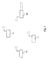
- reference signs T1, T2, ..., Tn designate a set of terminals including any number (including one) of terminals to be connected to form a wireless network including a base station BS.
- the terminals may be of any known type, mobile or fixed, and be identical or different from each other. While designated a base station (BS) in connection with its operation as described in the following, the base station may be in itself or include a network terminal (mobile or fixed) and/or act as an access point (AP) for the network illustrated in Figure 1 .
- BS base station
- AP access point
- Mobile communication networks e.g. 3G mobile networks and beyond
- Wireless Local Area Networks W-LANS
- WiMAX Wireless Local Area Networks
- Access of terminals T1, T2, ..., Tn to the network involves a Network Entry procedure (performed according to principles that are known per se and do not require to be explained in detail herein).
- the terminal seeks to establish communication with the base station BS until it receives a confirmation response from the base station BS.
- the terminal T1 starts from an initial power level, and in case no response is received from the base station BS, the terminal T1 gradually increases its transmission power up to a maximum value, and possibly "wraps back" to the initial value, restarting the procedure from the beginning, if no response is received from the base station BS.
- the terminal T1 identifies (in manner known per se, e.g. by reading it in a table of configuration values or by calculating it on the basis of a formula of the type reproduced in the foregoing) an initial power level to be used in the Initial Ranging process of the Network Entry procedure.
- a step 104 the terminal identifies (again in a manner known per se, e.g. by reading it in a table of configuration values or by calculating it according to a given formula) a maximum allowed power level (e.g. P TX_IR_MAX ) to be used in the Network Entry procedure.
- a maximum allowed power level e.g. P TX_IR_MAX
- a check is made as to whether the power level currently used by the terminal T1 is not in excess of the maximum level allowed and, if that is the case, the terminal T1 performs a set of operations (which are known per se e.g. from the standards cited in the introductory portion of this description) intended to establish communication with the base station BS.
- the base station BS will send a response to the terminal T1.
- Whether such a response is received is checked in a step 110, and in the positive (i.e. a response is received from the base station BS) the Network Entry procedure is completed (by possibly performing other operations not illustrated, but of a known type) as indicated by a stop step 112.
- step 110 yields a negative outcome (i.e. no response was received from the base station BS)
- step 114 the terminal power is increased of a given amount (set according to known criteria) and the attempt to obtain a response from the base station BS is repeated using an increased power level.
- the arrangement described evolves to the step 104 (via a step 116 to be described in the following) by resetting the maximum level admitted.
- a level P MAX_CAP is substituted corresponding to the maximum power capability of the terminal T1.
- the terminal admitted power range that is the range admitted for power increases (see the step 114) by the terminal, is extended upwardly to the maximum power capability of the terminal T1.
- the step 106 will again permit the steps 108 to 114 to be repeated by using power values that are increased beyond the maximum level previously set (e.g. P TX_IR_MAX ) in order to attempt to establish communication with the base station BS and obtain a response from it by being able to exploit the maximum power capability of the terminal T1.
- P TX_IR_MAX the maximum level previously set
- the terminal T1 will "wrap back" (step 118) to the initial value (and possibly activate the back-off procedure described in the foregoing and/or abort the Network Entry procedure with the specified channel after a given number of repeated attempts without communication being established) only after the power is gradually increased (via steps 114) - without having a response from the base station BS - up to the maximum power capability P MAX_CAP of the terminal, namely up to the point where no further power increases are possible.
- the step 106 will indicates that further increases exceed the maximum power capability of the terminal T1 and the step 116 indicates that the maximum level has been already been reset to P MAX_CAP , i.e. the maximum power capability of the terminal T1.
- the embodiment to which the flow chart of figure 2 refers retains the advantages inherent in setting a maximum level for the power used by a terminal in performing Network Entry.(i.e. avoiding that a high transmission power, likely to "spoil" signals from other terminals in the network, is unnecessarily used), while also avoiding that a terminal may be finally excluded from entry to a network due to being prevented from exploiting its full power capability.
- the specific embodiment illustrated in the flow chart of Figure 2 refers provides for "wrapping back" to the initial level if no responses are received - after - the terminal power has been allowed to increase beyond the upper limit P TX_IR_MAX originally set towards the level P MAX_CAP corresponding to the maximum power capability of the terminal T1.
- the flow chart of Figure 3 refers to an alternative embodiment where the "threshold" level used in the step 106 is directly set in the step 104 to the value P MAX_CAP corresponding to the maximum power capability of the terminal T1 following a configuration step 120.
- Such configuration may take place already during the manufacture/installation of the terminal T1 in those cases (e.g. a FDD system with asymmetric "downlink” and “uplink” channels) where a successful Network Entry procedure is expected to almost invariably require exploiting the maximum power capability of the terminal T1.
Landscapes
- Engineering & Computer Science (AREA)
- Computer Networks & Wireless Communication (AREA)
- Signal Processing (AREA)
- Mobile Radio Communication Systems (AREA)
- Communication Control (AREA)
Abstract
Description
- The invention relates to techniques for controlling entry of terminals in wireless communication networks such as mobile communication networks.
- Network Entry is the procedure by means of which a terminal (mobile or fixed) "enters" a wireless communication network including any number of base stations.
- Basic telecommunication standards such as 802.16-2004 and 802.16-2005 specify the steps necessary to complete this task, i.e. Network Entry. One of the key factors that come into play in the related procedure is the maximum transmission power allowed for a terminal entering the network.
- In fact, during normal operation, that is, once the terminal has already entered the network, the power level of the terminal is adjusted as a function of measurements performed at the base station. Conversely, during the initial steps of the Network Entry procedure, e.g. Initial Ranging, the maximum allowed power is determined by the terminal itself.
- For instance, the terminal seeking entry to the network may calculate a value for its maximum allowed power PTX_IR_MAX on the basis of the following relationship:

where: - EIRxPIR,max is the maximum equivalent isotropic received power at the terminal, that is the effective power measured at the antenna receiver,
- RSS is the received signal strength at the antenna output,
- BS_EIRP is the equivalent isotropic radiated power of the base station, that is the effective power measured at the antenna transmitter, and
- GRx_ss and GTx_ss are the receiver and terminal antenna gain at the terminal.
- The terminal will start the network entry procedure by using a given power level, e.g. the level PTX_IR_MXX calculated as indicated in the foregoing or, possibly, e.g. in case this value cannot be calculated, a minimum reference level (which may be lower than PTX_IR_MAX).
- Typically, during the Network Entry procedure, the terminal attempts to establish communication with the base station expected to serve it until it receives a response from the base station. In so doing, the terminal starts from a given initial power level, and, in case no response is received from the base station, the terminal gradually increases its transmission power up to a maximum value, and possibly "wraps back" to the initial value, restarting the procedure from the beginning, if no response is received from the base station.
- Typically, after a given number of repeated attempts without being able to establish communication (i.e. without network entry being achieved) a back-off procedure is initiated: since a limited number of entries is available, the terminal generates a random number in order to determine the entry to be used for network entry. In case of failure, a new number is tried up to a maximum number of retry attempts. Once this maximum number is reached, the channel is "marked" as unusable and the terminal looks for a new channel where the Network Entry procedure is re-started from the beginning.
- Despite the intrinsic simplicity of the procedure outlined above, a key issue arises in properly defining the "maximum value" of the power allowed for a terminal during the Network Entry procedure, that is the upper bound of the terminal admitted power range over which the terminal is allowed to set its power during the network entry procedure.
- In fact, in the case of TDD (Time Domain Division) systems, terminals that are very close to the base station may end up by using an unnecessarily high transmission power, possibly "spoiling" (i.e. causing disturbance to) signals received from other terminals. Limiting the power level used during the network entry procedure to a maximum value such as e.g. PTX_IR_MAX may thus be advantageous in that case.
- However, taking e.g. PTX_IR_MAX as the maximum power value admitted may lead a terminal being finally excluded from entering the network due to its inability to receive any response from the base station simply because that terminal was prevented from raising its power to a level (in excess of PTX_IR_MAX) high enough to enable the base station to "hear" it. This is particularly the case for terminals that are located at the edge of a cell.
- On the one hand, the formula for PTX_IR_MAX given in the foregoing may be said to take into account the fact that a terminal can be both close to the base station or at the edge of the cell, so that no limitations are imposed on the terminal. In fact, current experience shows that a maximum value corresponding to the value PTX_IR_MAX calculated as specified in the foregoing (i.e. on the basis of parameters provided by the base station which are the results of theoretical assumptions) is generally satisfactory for systems such as TDD systems.
- On the other hand, in other systems such as e.g. FDD (Frequency Domain Division) systems, where "downlink" and "uplink" channels may be asymmetric, the value given by PTX_IR_MAX, which is based on theoretical assumptions plus measurements on the downlink channel, the results may be unsatisfactory and lead to the disadvantages outlined in the foregoing (e.g. terminals being unduly prevented from entering a network).
- The Applicant has thus tackled the problem of devising an improved network entry procedure that complies in a fully satisfactory manner to the otherwise conflicting requirements outlined in the foregoing.
- The Applicant has found that this problem can be solved by means of a method having the features set forth in claim 1. Advantageous developments of the invention form the subject-matter of the subclaims. The invention also relates to a corresponding terminal and a corresponding computer program product, loadable in the memory of at least one computer and including software code portions for performing the steps of the method of the invention when the product is run on a computer. As used herein, reference to such a computer program product is intended to be equivalent to reference to a computer-readable medium containing instructions for controlling a computer system to coordinate the performance of the method of the invention. Reference to "at least one computer" is evidently intended to highlight the possibility for the present invention to be implemented in a distributed/modular fashion.
- The claims are an integral part of the disclosure of the invention provided herein.
- A preferred embodiment of the arrangement described herein is thus a terminal for connection to a base station in a wireless network which, during the entry procedure to the network, is allowed to possibly increase its power to reach its maximum power (i.e. its maximum power capability) in the absence of an answer from the base station during initial ranging. Allowing the terminal to reach its maximum capability in the absence of an answer from the base station would result in the cell radius (especially for fixed system) being enlarged, without any upper bound as given e.g. by the formula for PTX_IR_MAX given in the foregoing.
- Stated otherwise, the approach underlying the current standards for network entry can be summarized as follows: "If, during initialization, power is increased to the maximum value, without a response from the base station (BS), it (i.e. the terminal) shall wrap back to the minimum.".
- As opposed thereto, the approach underlying the preferred embodiment of the arrangement described herein can be summarized as follows: "If, during initialization, power is increased to the maximum value (e.g. PTX_IR_MAX for TDD)or to its maximum capability (e.g. for FDD) -- without a response from the base station (BS) it shall wrap back to the minimum."
- The arrangement described herein thus enables different systems to perform at their best, according to their specific capabilities.
- In fact, if the terminal does not receive any response from the base station, a substantial likelihood exists that either a collision has occurred or the signal is not good enough. Consequently, increasing the terminal power (if possible - i.e. over a terminal admitted power range which extends up to the maximum power capability of the terminal) is a thoroughly sensible approach.
- The invention will now be described, by way of example only, with reference to the enclosed figures of drawing, wherein:
-
Figure 1 is a block diagram of a wireless communication network adapted to include the arrangement described herein, and -
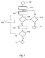
Figures 2 and3 are two flow charts exemplary of different types of operation of the arrangement described herein. - In the block diagram of
Figure 1 , reference signs T1, T2, ..., Tn designate a set of terminals including any number (including one) of terminals to be connected to form a wireless network including a base station BS. - The terminals may be of any known type, mobile or fixed, and be identical or different from each other. While designated a base station (BS) in connection with its operation as described in the following, the base station may be in itself or include a network terminal (mobile or fixed) and/or act as an access point (AP) for the network illustrated in
Figure 1 . - Mobile communication networks (e.g. 3G mobile networks and beyond) and Wireless Local Area Networks (W-LANS) such as WiMAX are exemplary of a wireless network as illustrated in
Figure 1 . - Access of terminals T1, T2, ..., Tn to the network involves a Network Entry procedure (performed according to principles that are known per se and do not require to be explained in detail herein). During the entry procedure, the terminal (terminal T1 will be hereinafter referred to as a non limiting example) seeks to establish communication with the base station BS until it receives a confirmation response from the base station BS. The terminal T1 starts from an initial power level, and in case no response is received from the base station BS, the terminal T1 gradually increases its transmission power up to a maximum value, and possibly "wraps back" to the initial value, restarting the procedure from the beginning, if no response is received from the base station BS.
- By referring to the flow chart of
Figure 2 , after astart step 100, in astep 102 the terminal T1 identifies (in manner known per se, e.g. by reading it in a table of configuration values or by calculating it on the basis of a formula of the type reproduced in the foregoing) an initial power level to be used in the Initial Ranging process of the Network Entry procedure. - In a
step 104 the terminal identifies (again in a manner known per se, e.g. by reading it in a table of configuration values or by calculating it according to a given formula) a maximum allowed power level (e.g. PTX_IR_MAX) to be used in the Network Entry procedure. - In a control step 106 a check is made as to whether the power level currently used by the terminal T1 is not in excess of the maximum level allowed and, if that is the case, the terminal T1 performs a set of operations (which are known per se e.g. from the standards cited in the introductory portion of this description) intended to establish communication with the base station BS.
- If these operations (collectively represented by the
block 108 in the diagram ofFigure 2 ) are successful, the base station BS will send a response to the terminal T1. - Whether such a response is received is checked in a
step 110, and in the positive (i.e. a response is received from the base station BS) the Network Entry procedure is completed (by possibly performing other operations not illustrated, but of a known type) as indicated by astop step 112. - If the
step 110 yields a negative outcome (i.e. no response was received from the base station BS), in astep 114 the terminal power is increased of a given amount (set according to known criteria) and the attempt to obtain a response from the base station BS is repeated using an increased power level. - The sequence of steps described is repeated until either the
step 110 yields a positive outcome (i.e. a response is received from the base station BS) or thestep 106 indicates that no further increases of the power level are possible without exceeding the maximum level PTX_IR_MAX set in thestep 104. - Contrary to conventional arrangements (which at this point would "wrap back" to the initial value minimum and possibly activate the back-off procedure after a given number of repeated attempts without communication being established), the arrangement described evolves to the step 104 (via a
step 116 to be described in the following) by resetting the maximum level admitted. - Specifically, to the upper limit previously set (e.g. PTX_IR_MAX) a level PMAX_CAP is substituted corresponding to the maximum power capability of the terminal T1. In that way, the terminal admitted power range, that is the range admitted for power increases (see the step 114) by the terminal, is extended upwardly to the maximum power capability of the terminal T1.
- At this point, the
step 106 will again permit thesteps 108 to 114 to be repeated by using power values that are increased beyond the maximum level previously set (e.g. PTX_IR_MAX) in order to attempt to establish communication with the base station BS and obtain a response from it by being able to exploit the maximum power capability of the terminal T1. - In fact, in the arrangement described herein, the terminal T1 will "wrap back" (step 118) to the initial value (and possibly activate the back-off procedure described in the foregoing and/or abort the Network Entry procedure with the specified channel after a given number of repeated attempts without communication being established) only after the power is gradually increased (via steps 114) - without having a response from the base station BS - up to the maximum power capability PMAX_CAP of the terminal, namely up to the point where no further power increases are possible. In that case the
step 106 will indicates that further increases exceed the maximum power capability of the terminal T1 and thestep 116 indicates that the maximum level has been already been reset to PMAX_CAP, i.e. the maximum power capability of the terminal T1. - The embodiment to which the flow chart of
figure 2 refers retains the advantages inherent in setting a maximum level for the power used by a terminal in performing Network Entry.(i.e. avoiding that a high transmission power, likely to "spoil" signals from other terminals in the network, is unnecessarily used), while also avoiding that a terminal may be finally excluded from entry to a network due to being prevented from exploiting its full power capability. - The specific embodiment illustrated in the flow chart of
Figure 2 refers provides for "wrapping back" to the initial level if no responses are received - after - the terminal power has been allowed to increase beyond the upper limit PTX_IR_MAX originally set towards the level PMAX_CAP corresponding to the maximum power capability of the terminal T1. - Those of skill in the art will however appreciate that, in a presently less preferred variant, "wrapping back" to the initial minimum power level may take place (also) - before - the terminal power is allowed to increase beyond the upper limit PTX_IR_MAX originally set towards the maximum power capability PMAX_CAP. Stated otherwise, in such a case the terminal T1 will repeatedly perform "power increase and wrap back" cycles with PTX_IR_MAX as the upper power limit, and then, in the absence of any response from the base station BS, perform one or more "power increase and wrap back" cycles within a terminal admitted power range extended upward to the maximum power capability of the terminal T1 PMAX_CAP. In such a case, the Network Entry procedure will be repeatedly attempted with the limitation of the output power to PTX_IR_MAX before removing this limitation to fully exploit the maximum power capability PMAX_CAP of the terminal T1.
- The flow chart of
Figure 3 (where the same reference numerals have been used to designate steps /operations identical or equivalent to those already described in connection with the flowchart ofFigure 2 ) refers to an alternative embodiment where the "threshold" level used in thestep 106 is directly set in thestep 104 to the value PMAX_CAP corresponding to the maximum power capability of the terminal T1 following aconfiguration step 120. Such configuration may take place already during the manufacture/installation of the terminal T1 in those cases (e.g. a FDD system with asymmetric "downlink" and "uplink" channels) where a successful Network Entry procedure is expected to almost invariably require exploiting the maximum power capability of the terminal T1. - Of course, still other alternative embodiments are possible, including, but not limited to, embodiments that incorporate the features of both embodiments illustrated in the flow charts of
Figures 2 and3 i.e. embodiments that are selectively configurable to attempt Network Entry by first limiting the output power and then exploiting the full power capability or to attempt from the very beginning Network Entry without any limitation on the output power, or embodiments where Network Entry is attempted from the very beginning by using the full power capability of the terminal. - Consequently, without prejudice to the underlying principles of the invention, the details and the embodiments may vary, even appreciably, with reference to what has been described by way of example only, without departing from the scope of the invention as defined by the annexed claims.
Claims (9)
- A method of performing network entry of a terminal (T1) to a wireless network including a base station (BS), said terminal having a maximum power capability (PMAX_CAP), the method including at least one attempt by said terminal (T1) to establish communication with said base station (BS) with a power level (102) within a terminal admitted power range, wherein said terminal admitted power range extends up to said maximum power capability (PMAX_CAP) of the terminal.
- The method of claim 1, including at least one attempt by said terminal (T1) to establish communication with said base station (BS) with an initial power level (102) within said terminal admitted power range, and, in the absence of a response from said base station (BS), at least one repeated attempt by said terminal (T1) to establish communication with said base station (BS) with a power level increased (114) over said initial power level (102) within said terminal admitted power range.
- The method of claim 2, including at least one repeated attempt by said terminal (T1) to establish communication with said base station (BS) with a power level increased (114) up to said maximum power capability (PMAX_CAP) of the terminal.
- The method of either of claims 2 or 3, including, in the absence of a response from said base station, at least one further attempt by said terminal (T1) to establish communication with said base station (BS) with a power level wrapped back to said initial power level (102).
- The method of claims 3 and 4, including said at least one further attempt with a power level wrapped back to said initial power level (102) performed by said terminal (T1) after said at least one repeated attempt by said terminal (T1) to establish communication with said base station (BS) with a power level increased (114) up to said maximum power capability (PMAX_CAP) of the terminal.
- The method of claim 2, including:- setting an initial upper limit (PTX_IR_MAX) for said terminal admitted power range,- said at least one repeated attempt by said terminal (T1) to establish communication with said base station (BS) with a power level increased (114) over said initial power level (102) within said terminal admitted power range limited by said initial upper limit (PTX_IR_MAX),- in the absence of a response from said base station (BS), extending said terminal admitted power range beyond said initial upper limit (PTX_IR_MAX) up to said maximum power capability (PMAX_CAP) of the terminal; and- at least another repeated attempt by said terminal (T1) to establish communication with said base station (BS) with a power level increased (114) in excess of said initial upper limit (PTX_IR_MAX).
- The method of claim 1, including the step of extending said terminal admitted power range up to said maximum power capability (PMAX_CAP) of the terminal as a step of terminal configuration (120).
- A terminal (T1) for a wireless network including a base station (BS), said terminal having a maximum power capability (PMAX_CAP) and being configured for performing network entry to said wireless network according to the method of any of claims 1 to 7.
- A computer program product loadable in the memory of at least one computer and including software code portions for performing the steps of any of claims 1 to 7.
Priority Applications (6)
| Application Number | Priority Date | Filing Date | Title |
|---|---|---|---|
| AT07425009T ATE478532T1 (en) | 2007-01-12 | 2007-01-12 | METHOD FOR INPUT CONTROL OF TERMINAL DEVICES IN WIRELESS COMMUNICATION NETWORKS, CORRESPONDING TERMINAL DEVICE AND COMPUTER PROGRAM PRODUCT |
| DE602007008519T DE602007008519D1 (en) | 2007-01-12 | 2007-01-12 | Method for input control of terminals in wireless communication networks, corresponding terminal and computer program product |
| ES07425009T ES2351042T3 (en) | 2007-01-12 | 2007-01-12 | PROCEDURE TO CONTROL THE ENTRY OF TERMINALS TO WIRELESS COMMUNICATION NETWORKS, TERMINAL AND CORRESPONDING COMPUTER PROGRAM PRODUCT. |
| EP07425009A EP1944880B1 (en) | 2007-01-12 | 2007-01-12 | A method of controlling entry of terminals in wireless communication networks, corresponding terminal and computer program product |
| CA002617426A CA2617426A1 (en) | 2007-01-12 | 2008-01-09 | A method of controlling entry of terminals in wireless communication networks, corresponding terminal and computer program product |
| US12/008,242 US8023986B2 (en) | 2007-01-12 | 2008-01-09 | Mobile terminal entry based on power control within maximum admitted power range |
Applications Claiming Priority (1)
| Application Number | Priority Date | Filing Date | Title |
|---|---|---|---|
| EP07425009A EP1944880B1 (en) | 2007-01-12 | 2007-01-12 | A method of controlling entry of terminals in wireless communication networks, corresponding terminal and computer program product |
Publications (2)
| Publication Number | Publication Date |
|---|---|
| EP1944880A1 true EP1944880A1 (en) | 2008-07-16 |
| EP1944880B1 EP1944880B1 (en) | 2010-08-18 |
Family
ID=37989007
Family Applications (1)
| Application Number | Title | Priority Date | Filing Date |
|---|---|---|---|
| EP07425009A Active EP1944880B1 (en) | 2007-01-12 | 2007-01-12 | A method of controlling entry of terminals in wireless communication networks, corresponding terminal and computer program product |
Country Status (6)
| Country | Link |
|---|---|
| US (1) | US8023986B2 (en) |
| EP (1) | EP1944880B1 (en) |
| AT (1) | ATE478532T1 (en) |
| CA (1) | CA2617426A1 (en) |
| DE (1) | DE602007008519D1 (en) |
| ES (1) | ES2351042T3 (en) |
Families Citing this family (2)
| Publication number | Priority date | Publication date | Assignee | Title |
|---|---|---|---|---|
| EP2053764B1 (en) * | 2007-10-25 | 2014-08-13 | Rohde & Schwarz GmbH & Co. KG | Method and device for transmitter calibration |
| US9031044B2 (en) * | 2008-08-20 | 2015-05-12 | Qualcomm Incorporated | Power control for wireless LAN stations |
Citations (2)
| Publication number | Priority date | Publication date | Assignee | Title |
|---|---|---|---|---|
| WO2003003643A1 (en) | 2001-06-27 | 2003-01-09 | Nokia Corporation | Method for adaptively setting transmission parameters for a random access channel transmission uplink procedure in a wireless communication system |
| US20050164742A1 (en) | 2004-01-23 | 2005-07-28 | Samsung Electronics Co., Ltd. | Apparatus and method for improved call release in a wireless network |
Family Cites Families (5)
| Publication number | Priority date | Publication date | Assignee | Title |
|---|---|---|---|---|
| US6941152B2 (en) * | 2001-04-24 | 2005-09-06 | Ipr Licensing, Inc. | Wireless subscriber network registration system for configurable services |
| US7046966B2 (en) * | 2001-08-24 | 2006-05-16 | Kyocera Wireless Corp. | Method and apparatus for assigning data rate in a multichannel communication system |
| US7239884B2 (en) * | 2003-01-23 | 2007-07-03 | Motorola, Inc. | Method for providing improved access times for a communication device |
| KR100827117B1 (en) * | 2005-03-29 | 2008-05-02 | 삼성전자주식회사 | Method and apparatus for transmitting maximum transmitter power information of terminal to base station for scheduling uplink packet transmission in mobile communication system |
| AU2005336604B2 (en) * | 2005-09-22 | 2010-06-17 | Blackberry Limited | Mobile station, fixed station, communication system and communication method |
-
2007
- 2007-01-12 AT AT07425009T patent/ATE478532T1/en not_active IP Right Cessation
- 2007-01-12 DE DE602007008519T patent/DE602007008519D1/en active Active
- 2007-01-12 EP EP07425009A patent/EP1944880B1/en active Active
- 2007-01-12 ES ES07425009T patent/ES2351042T3/en active Active
-
2008
- 2008-01-09 CA CA002617426A patent/CA2617426A1/en not_active Abandoned
- 2008-01-09 US US12/008,242 patent/US8023986B2/en active Active
Patent Citations (2)
| Publication number | Priority date | Publication date | Assignee | Title |
|---|---|---|---|---|
| WO2003003643A1 (en) | 2001-06-27 | 2003-01-09 | Nokia Corporation | Method for adaptively setting transmission parameters for a random access channel transmission uplink procedure in a wireless communication system |
| US20050164742A1 (en) | 2004-01-23 | 2005-07-28 | Samsung Electronics Co., Ltd. | Apparatus and method for improved call release in a wireless network |
Non-Patent Citations (2)
| Title |
|---|
| SCHULIST M ET AL.: "LINK LEVEL PERFORMANCE RESULTS FOR A WCDMA RANDOM ACCESS SCHEME WITH PREAMBLE POWER RAMPING AND FAST ACQUISITION INDICATION", VTC 1999-FALL. IEEE VTS 50TH. VEHICULAR TECHNOLOGY CONFERENCE. GATEWAY TO THE 21ST. CENTURY COMMUNICATIONS VILLAGE, vol. 5, 19 September 1999 (1999-09-19), pages 2581 - 2585 |
| SCHULIST M ET AL: "LINK LEVEL PERFORMANCE RESULTS FOR A WCDMA RANDOM ACCESS SCHEME WITH PREAMBLE POWER RAMPING AND FAST ACQUISITION INDICATION", VTC 1999-FALL. IEEE VTS 50TH. VEHICULAR TECHNOLOGY CONFERENCE. GATEWAY TO THE 21ST. CENTURY COMMUNICATIONS VILLAGE. AMSTERDAM, SEPT. 19 - 22, 1999, IEEE VEHICULAR TECHNOLGY CONFERENCE, NEW YORK, NY : IEEE, US, vol. VOL. 5 CONF. 50, 19 September 1999 (1999-09-19), pages 2581 - 2585, XP010353371, ISBN: 0-7803-5436-2 * |
Also Published As
| Publication number | Publication date |
|---|---|
| US8023986B2 (en) | 2011-09-20 |
| US20080182610A1 (en) | 2008-07-31 |
| EP1944880B1 (en) | 2010-08-18 |
| CA2617426A1 (en) | 2008-07-12 |
| ATE478532T1 (en) | 2010-09-15 |
| ES2351042T3 (en) | 2011-01-31 |
| DE602007008519D1 (en) | 2010-09-30 |
Similar Documents
| Publication | Publication Date | Title |
|---|---|---|
| US11902915B2 (en) | Communication method and communications apparatus | |
| EP3050371B1 (en) | Method and apparatus for ue power class adaptation for coverage extension in lte | |
| US11778668B2 (en) | Communication method and device | |
| EP4090124A1 (en) | Method and apparatus for transmitting msg3 | |
| US20190268883A1 (en) | Method and apparatus for bandwidth indication in unlicensed spectrum | |
| EP3054737A1 (en) | Communication device and wireless communication system for handling random access procedure | |
| EP3565316A1 (en) | Random access method, user equipment and network device | |
| CN113993150B (en) | Beam management method and device, user equipment, chip and computer medium | |
| EP2355598B1 (en) | Radio base station, wireless communication system, method for controlling transmission power of radio base station, and recording medium of program for controlling transmission power of radio base station | |
| US10206227B2 (en) | Device and method of setting clear channel assessment threshold | |
| EP3397009A1 (en) | Methods and devices in a communications network | |
| EP3927001A1 (en) | Method, device, and system for transmitting sounding reference signal | |
| CN112385285A (en) | Random access method and device | |
| TW202512785A (en) | Sidelink feedback information | |
| US20220182940A1 (en) | Discontinuous reception processing method, and terminal device | |
| US10187132B2 (en) | Communication terminal and method for selecting a transmission antenna | |
| US20210168727A1 (en) | Uplink transmit power determining method, network device, and storage medium | |
| JP2013232948A (en) | Method and arrangement in telecommunication system | |
| US8023986B2 (en) | Mobile terminal entry based on power control within maximum admitted power range | |
| US11382045B2 (en) | Device and method of handling a transmission based on spatial reuse | |
| EP3993546A1 (en) | Random access method and device, and terminal | |
| US20250317961A1 (en) | Method and Communication Device for Handling Uplink Transmission | |
| KR102962150B1 (en) | Power control method and apparatus | |
| US20250317934A1 (en) | Method and Communication Device for Handling Uplink Transmission | |
| US20250317780A1 (en) | Method and Communication Device for Handling Uplink Transmission |
Legal Events
| Date | Code | Title | Description |
|---|---|---|---|
| PUAI | Public reference made under article 153(3) epc to a published international application that has entered the european phase |
Free format text: ORIGINAL CODE: 0009012 |
|
| AK | Designated contracting states |
Kind code of ref document: A1 Designated state(s): AT BE BG CH CY CZ DE DK EE ES FI FR GB GR HU IE IS IT LI LT LU LV MC NL PL PT RO SE SI SK TR |
|
| AX | Request for extension of the european patent |
Extension state: AL BA HR MK RS |
|
| 17P | Request for examination filed |
Effective date: 20090116 |
|
| 17Q | First examination report despatched |
Effective date: 20090219 |
|
| AKX | Designation fees paid |
Designated state(s): AT BE BG CH CY CZ DE DK EE ES FI FR GB GR HU IE IS IT LI LT LU LV MC NL PL PT RO SE SI SK TR |
|
| RIC1 | Information provided on ipc code assigned before grant |
Ipc: H04W 52/36 20090101ALI20091221BHEP Ipc: H04W 52/48 20090101AFI20091221BHEP Ipc: H04W 52/50 20090101ALI20091221BHEP |
|
| GRAP | Despatch of communication of intention to grant a patent |
Free format text: ORIGINAL CODE: EPIDOSNIGR1 |
|
| GRAS | Grant fee paid |
Free format text: ORIGINAL CODE: EPIDOSNIGR3 |
|
| GRAA | (expected) grant |
Free format text: ORIGINAL CODE: 0009210 |
|
| AK | Designated contracting states |
Kind code of ref document: B1 Designated state(s): AT BE BG CH CY CZ DE DK EE ES FI FR GB GR HU IE IS IT LI LT LU LV MC NL PL PT RO SE SI SK TR |
|
| REG | Reference to a national code |
Ref country code: GB Ref legal event code: FG4D |
|
| REG | Reference to a national code |
Ref country code: CH Ref legal event code: EP |
|
| REG | Reference to a national code |
Ref country code: IE Ref legal event code: FG4D |
|
| REF | Corresponds to: |
Ref document number: 602007008519 Country of ref document: DE Date of ref document: 20100930 Kind code of ref document: P |
|
| REG | Reference to a national code |
Ref country code: NL Ref legal event code: T3 |
|
| LTIE | Lt: invalidation of european patent or patent extension |
Effective date: 20100818 |
|
| PG25 | Lapsed in a contracting state [announced via postgrant information from national office to epo] |
Ref country code: LT Free format text: LAPSE BECAUSE OF FAILURE TO SUBMIT A TRANSLATION OF THE DESCRIPTION OR TO PAY THE FEE WITHIN THE PRESCRIBED TIME-LIMIT Effective date: 20100818 Ref country code: FI Free format text: LAPSE BECAUSE OF FAILURE TO SUBMIT A TRANSLATION OF THE DESCRIPTION OR TO PAY THE FEE WITHIN THE PRESCRIBED TIME-LIMIT Effective date: 20100818 Ref country code: AT Free format text: LAPSE BECAUSE OF FAILURE TO SUBMIT A TRANSLATION OF THE DESCRIPTION OR TO PAY THE FEE WITHIN THE PRESCRIBED TIME-LIMIT Effective date: 20100818 |
|
| REG | Reference to a national code |
Ref country code: ES Ref legal event code: FG2A Effective date: 20110119 |
|
| PG25 | Lapsed in a contracting state [announced via postgrant information from national office to epo] |
Ref country code: BG Free format text: LAPSE BECAUSE OF FAILURE TO SUBMIT A TRANSLATION OF THE DESCRIPTION OR TO PAY THE FEE WITHIN THE PRESCRIBED TIME-LIMIT Effective date: 20101118 Ref country code: PT Free format text: LAPSE BECAUSE OF FAILURE TO SUBMIT A TRANSLATION OF THE DESCRIPTION OR TO PAY THE FEE WITHIN THE PRESCRIBED TIME-LIMIT Effective date: 20101220 Ref country code: CY Free format text: LAPSE BECAUSE OF FAILURE TO SUBMIT A TRANSLATION OF THE DESCRIPTION OR TO PAY THE FEE WITHIN THE PRESCRIBED TIME-LIMIT Effective date: 20100818 Ref country code: IS Free format text: LAPSE BECAUSE OF FAILURE TO SUBMIT A TRANSLATION OF THE DESCRIPTION OR TO PAY THE FEE WITHIN THE PRESCRIBED TIME-LIMIT Effective date: 20101218 Ref country code: PL Free format text: LAPSE BECAUSE OF FAILURE TO SUBMIT A TRANSLATION OF THE DESCRIPTION OR TO PAY THE FEE WITHIN THE PRESCRIBED TIME-LIMIT Effective date: 20100818 Ref country code: SI Free format text: LAPSE BECAUSE OF FAILURE TO SUBMIT A TRANSLATION OF THE DESCRIPTION OR TO PAY THE FEE WITHIN THE PRESCRIBED TIME-LIMIT Effective date: 20100818 |
|
| PG25 | Lapsed in a contracting state [announced via postgrant information from national office to epo] |
Ref country code: LV Free format text: LAPSE BECAUSE OF FAILURE TO SUBMIT A TRANSLATION OF THE DESCRIPTION OR TO PAY THE FEE WITHIN THE PRESCRIBED TIME-LIMIT Effective date: 20100818 Ref country code: SE Free format text: LAPSE BECAUSE OF FAILURE TO SUBMIT A TRANSLATION OF THE DESCRIPTION OR TO PAY THE FEE WITHIN THE PRESCRIBED TIME-LIMIT Effective date: 20100818 Ref country code: GR Free format text: LAPSE BECAUSE OF FAILURE TO SUBMIT A TRANSLATION OF THE DESCRIPTION OR TO PAY THE FEE WITHIN THE PRESCRIBED TIME-LIMIT Effective date: 20101119 Ref country code: BE Free format text: LAPSE BECAUSE OF FAILURE TO SUBMIT A TRANSLATION OF THE DESCRIPTION OR TO PAY THE FEE WITHIN THE PRESCRIBED TIME-LIMIT Effective date: 20100818 |
|
| PG25 | Lapsed in a contracting state [announced via postgrant information from national office to epo] |
Ref country code: DK Free format text: LAPSE BECAUSE OF FAILURE TO SUBMIT A TRANSLATION OF THE DESCRIPTION OR TO PAY THE FEE WITHIN THE PRESCRIBED TIME-LIMIT Effective date: 20100818 |
|
| PG25 | Lapsed in a contracting state [announced via postgrant information from national office to epo] |
Ref country code: RO Free format text: LAPSE BECAUSE OF FAILURE TO SUBMIT A TRANSLATION OF THE DESCRIPTION OR TO PAY THE FEE WITHIN THE PRESCRIBED TIME-LIMIT Effective date: 20100818 Ref country code: EE Free format text: LAPSE BECAUSE OF FAILURE TO SUBMIT A TRANSLATION OF THE DESCRIPTION OR TO PAY THE FEE WITHIN THE PRESCRIBED TIME-LIMIT Effective date: 20100818 Ref country code: CZ Free format text: LAPSE BECAUSE OF FAILURE TO SUBMIT A TRANSLATION OF THE DESCRIPTION OR TO PAY THE FEE WITHIN THE PRESCRIBED TIME-LIMIT Effective date: 20100818 Ref country code: SK Free format text: LAPSE BECAUSE OF FAILURE TO SUBMIT A TRANSLATION OF THE DESCRIPTION OR TO PAY THE FEE WITHIN THE PRESCRIBED TIME-LIMIT Effective date: 20100818 |
|
| PLBE | No opposition filed within time limit |
Free format text: ORIGINAL CODE: 0009261 |
|
| STAA | Information on the status of an ep patent application or granted ep patent |
Free format text: STATUS: NO OPPOSITION FILED WITHIN TIME LIMIT |
|
| 26N | No opposition filed |
Effective date: 20110519 |
|
| PG25 | Lapsed in a contracting state [announced via postgrant information from national office to epo] |
Ref country code: MC Free format text: LAPSE BECAUSE OF NON-PAYMENT OF DUE FEES Effective date: 20110131 |
|
| REG | Reference to a national code |
Ref country code: CH Ref legal event code: PL |
|
| REG | Reference to a national code |
Ref country code: DE Ref legal event code: R097 Ref document number: 602007008519 Country of ref document: DE Effective date: 20110519 |
|
| PG25 | Lapsed in a contracting state [announced via postgrant information from national office to epo] |
Ref country code: LI Free format text: LAPSE BECAUSE OF NON-PAYMENT OF DUE FEES Effective date: 20110131 Ref country code: CH Free format text: LAPSE BECAUSE OF NON-PAYMENT OF DUE FEES Effective date: 20110131 |
|
| PGFP | Annual fee paid to national office [announced via postgrant information from national office to epo] |
Ref country code: IT Payment date: 20120123 Year of fee payment: 6 |
|
| PGFP | Annual fee paid to national office [announced via postgrant information from national office to epo] |
Ref country code: ES Payment date: 20130128 Year of fee payment: 7 Ref country code: FR Payment date: 20130213 Year of fee payment: 7 Ref country code: IE Payment date: 20130122 Year of fee payment: 7 |
|
| PG25 | Lapsed in a contracting state [announced via postgrant information from national office to epo] |
Ref country code: LU Free format text: LAPSE BECAUSE OF NON-PAYMENT OF DUE FEES Effective date: 20110112 |
|
| PGFP | Annual fee paid to national office [announced via postgrant information from national office to epo] |
Ref country code: NL Payment date: 20130122 Year of fee payment: 7 |
|
| PG25 | Lapsed in a contracting state [announced via postgrant information from national office to epo] |
Ref country code: TR Free format text: LAPSE BECAUSE OF FAILURE TO SUBMIT A TRANSLATION OF THE DESCRIPTION OR TO PAY THE FEE WITHIN THE PRESCRIBED TIME-LIMIT Effective date: 20100818 |
|
| PG25 | Lapsed in a contracting state [announced via postgrant information from national office to epo] |
Ref country code: HU Free format text: LAPSE BECAUSE OF FAILURE TO SUBMIT A TRANSLATION OF THE DESCRIPTION OR TO PAY THE FEE WITHIN THE PRESCRIBED TIME-LIMIT Effective date: 20100818 |
|
| REG | Reference to a national code |
Ref country code: NL Ref legal event code: V1 Effective date: 20140801 |
|
| PG25 | Lapsed in a contracting state [announced via postgrant information from national office to epo] |
Ref country code: NL Free format text: LAPSE BECAUSE OF NON-PAYMENT OF DUE FEES Effective date: 20140801 |
|
| REG | Reference to a national code |
Ref country code: FR Ref legal event code: ST Effective date: 20140930 |
|
| REG | Reference to a national code |
Ref country code: IE Ref legal event code: MM4A |
|
| PG25 | Lapsed in a contracting state [announced via postgrant information from national office to epo] |
Ref country code: FR Free format text: LAPSE BECAUSE OF NON-PAYMENT OF DUE FEES Effective date: 20140131 |
|
| PG25 | Lapsed in a contracting state [announced via postgrant information from national office to epo] |
Ref country code: IE Free format text: LAPSE BECAUSE OF NON-PAYMENT OF DUE FEES Effective date: 20140112 |
|
| REG | Reference to a national code |
Ref country code: ES Ref legal event code: FD2A Effective date: 20150331 |
|
| PG25 | Lapsed in a contracting state [announced via postgrant information from national office to epo] |
Ref country code: ES Free format text: LAPSE BECAUSE OF NON-PAYMENT OF DUE FEES Effective date: 20140113 |
|
| PG25 | Lapsed in a contracting state [announced via postgrant information from national office to epo] |
Ref country code: IT Free format text: LAPSE BECAUSE OF NON-PAYMENT OF DUE FEES Effective date: 20140112 |
|
| REG | Reference to a national code |
Ref country code: DE Ref legal event code: R081 Ref document number: 602007008519 Country of ref document: DE Owner name: NOKIA SOLUTIONS AND NETWORKS ITALIA S.P.A., CA, IT Free format text: FORMER OWNER: NOKIA SIEMENS NETWORKS S.P.A., MILANO, IT |
|
| REG | Reference to a national code |
Ref country code: GB Ref legal event code: 732E Free format text: REGISTERED BETWEEN 20180222 AND 20180228 |
|
| PGFP | Annual fee paid to national office [announced via postgrant information from national office to epo] |
Ref country code: GB Payment date: 20251204 Year of fee payment: 20 |
|
| PGFP | Annual fee paid to national office [announced via postgrant information from national office to epo] |
Ref country code: DE Payment date: 20251203 Year of fee payment: 20 |