EP1944852A1 - Liquid-cooled machine - Google Patents
Liquid-cooled machine Download PDFInfo
- Publication number
- EP1944852A1 EP1944852A1 EP06445077A EP06445077A EP1944852A1 EP 1944852 A1 EP1944852 A1 EP 1944852A1 EP 06445077 A EP06445077 A EP 06445077A EP 06445077 A EP06445077 A EP 06445077A EP 1944852 A1 EP1944852 A1 EP 1944852A1
- Authority
- EP
- European Patent Office
- Prior art keywords
- stator
- cooling
- machine according
- machine
- radial
- Prior art date
- Legal status (The legal status is an assumption and is not a legal conclusion. Google has not performed a legal analysis and makes no representation as to the accuracy of the status listed.)
- Granted
Links
- 238000001816 cooling Methods 0.000 claims abstract description 40
- 239000000110 cooling liquid Substances 0.000 claims abstract description 16
- 238000004804 winding Methods 0.000 claims description 17
- 230000005284 excitation Effects 0.000 claims description 3
- 230000001419 dependent effect Effects 0.000 claims description 2
- LYCAIKOWRPUZTN-UHFFFAOYSA-N Ethylene glycol Chemical compound OCCO LYCAIKOWRPUZTN-UHFFFAOYSA-N 0.000 description 2
- XEEYBQQBJWHFJM-UHFFFAOYSA-N Iron Chemical compound [Fe] XEEYBQQBJWHFJM-UHFFFAOYSA-N 0.000 description 2
- 239000007788 liquid Substances 0.000 description 2
- 238000004519 manufacturing process Methods 0.000 description 2
- 238000000034 method Methods 0.000 description 2
- WGCNASOHLSPBMP-UHFFFAOYSA-N hydroxyacetaldehyde Natural products OCC=O WGCNASOHLSPBMP-UHFFFAOYSA-N 0.000 description 1
- 229910052742 iron Inorganic materials 0.000 description 1
- 239000002184 metal Substances 0.000 description 1
- 229910052751 metal Inorganic materials 0.000 description 1
- 239000000203 mixture Substances 0.000 description 1
- XLYOFNOQVPJJNP-UHFFFAOYSA-N water Substances O XLYOFNOQVPJJNP-UHFFFAOYSA-N 0.000 description 1
Images

Classifications
-
- H—ELECTRICITY
- H02—GENERATION; CONVERSION OR DISTRIBUTION OF ELECTRIC POWER
- H02K—DYNAMO-ELECTRIC MACHINES
- H02K9/00—Arrangements for cooling or ventilating
- H02K9/19—Arrangements for cooling or ventilating for machines with closed casing and closed-circuit cooling using a liquid cooling medium, e.g. oil
- H02K9/197—Arrangements for cooling or ventilating for machines with closed casing and closed-circuit cooling using a liquid cooling medium, e.g. oil in which the rotor or stator space is fluid-tight, e.g. to provide for different cooling media for rotor and stator
-
- H—ELECTRICITY
- H02—GENERATION; CONVERSION OR DISTRIBUTION OF ELECTRIC POWER
- H02K—DYNAMO-ELECTRIC MACHINES
- H02K1/00—Details of the magnetic circuit
- H02K1/06—Details of the magnetic circuit characterised by the shape, form or construction
- H02K1/12—Stationary parts of the magnetic circuit
- H02K1/20—Stationary parts of the magnetic circuit with channels or ducts for flow of cooling medium
-
- H—ELECTRICITY
- H02—GENERATION; CONVERSION OR DISTRIBUTION OF ELECTRIC POWER
- H02K—DYNAMO-ELECTRIC MACHINES
- H02K3/00—Details of windings
- H02K3/04—Windings characterised by the conductor shape, form or construction, e.g. with bar conductors
- H02K3/24—Windings characterised by the conductor shape, form or construction, e.g. with bar conductors with channels or ducts for cooling medium between the conductors
Definitions
- the present invention relates generally cooling and more particularly to cooling of a liquid-cooled machine.
- a high voltage machine needs cooling to work properly.
- the rotor of the machine is generally cooled by means of axially mounted fans, which push air into both ends of the rotor, which air thereafter is released from the machine through radial air ducts in the stator of the machine.
- the stator needs liquid cooling to work properly. It is however difficult to provide liquid cooling for a stator of a machine and still maintain good performance.
- An object of the present invention is to provide a machine having a liquid-cooled stator, which machine exhibit good performance.
- the invention is based on the realization that by providing the liquid-cooled stator with a radial cooling arrangement the machine exhibits good performance due to adequate cooling with little interference in the stator.
- a radial cooling arrangement comprises conduit means for conveying cooling liquid between a cable winding and a radial air duct the conduit means both directly cools the cable winding as well as shields the cable winding from air conveyed in the radial air duct, which air is heated by cooling of the rotor.
- the radial cooling arrangement is utilized to also form duct liners for the air ducts. This is readily provided by using a rectangular tube for conveying a cooling liquid therein. By using the radial cooling arrangement as duct liners a manufacturing step can be removed.
- a two-way conduit is formed, which inner divider preferably is a diagonal bulkhead.
- the cooling arrangement comprises a first inlet part, a second two-way part, a third middle part, a fourth two-way part and a fifth outlet part, and wherein the second, third and fourth part partly surrounds a plurality of the axial cable excitation windings the radial cooling arrangement occupy little space in the stator.
- the cooling arrangement preferably comprises a transfer chamber for the second two-way part as well as for the fourth two-way part.
- a machine particularly a very high voltage machine, comprises an inner air-cooled rotor 1 and an outer liquid-cooled stator 5.
- the rotor 1 has axial fans 3 and 4 mounted on its shaft 2. The fans 3 and 4 draw air onto the rotor 1 from its respective axial ends to cool the rotor 1 during use.
- the stator 5 preferably comprises radial air ducts 6 to convey the cooling air out from the machine.
- the stator 5 with its radial air ducts 6 is in Fig. 1 schematically illustrated by a vertical cut axially through the stator 5.
- a sectional part of the stator 5 is in Fig. 2 in more detail illustrated by a vertical cut radially through stator 5 along the line II-II in Fig. 1 .
- the stator 5 comprises a radial cooling arrangement 8 arranged to convey a cooling liquid, such as a mixture of water and glycol or an oil, radially in the stator 5.
- the stator comprises excitations windings in the form of axial cable windings 7 instead of conventional windings, which cable windings 7 are used to achieve very high voltages for the machine.
- the inventive cooling is particularly useful for cable-wound stators since the cables are relatively sensitive to heat and thus need efficient cooling. However, the inventive cooling is also applicable to machines using conventional windings, which also benefit of efficient cooling. By conveying the cooling liquid radially in the stator minimal amounts of iron need to be removed from the stator core and the power of the machine can thus be maximized.
- the cooling arrangement 8 preferably comprises conduit means, such as a cooling coil, for conveying the cooling liquid between the cable windings 7 and the radial air ducts 6.
- the conduit means forms duct liners for the radial air ducts 6. By making the conduit means of metal the power of the machine can be increased.
- the conduit means should preferably be located as close to the cable windings 7 as possible to not block the radial air duct 6.
- the conduit means comprises a rectangular tube 14 for conveying the cooling liquid therein.
- the rectangular tube 14 is suitable as duct liner and easy to manufacture, but the tube can however also have other desired cross-sections.
- the rectangular tube 14 includes a first inlet part 9, a second two-way part 10, a third middle part 11, a fourth two-way part 12 and a fifth outlet part 13.
- the two-way parts 10 and 12 are preferably formed by an inner divider 15, such as a diagonal bulkhead.
- the inner divider could however be formed also in other ways such as by an inner circular tube.
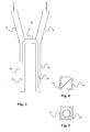
- a cooling coil is illustrated in Fig. 3 .
- the cooling liquid enters the conduit means through the first inlet part 9.
- the cooling liquid thereafter enters a first half of the second two-way part 10.
- At the radial inner end of the second two-way part 10 is a transfer chamber arranged that transfers the cooling liquid back into the other half of the second two-way part 10.
- the cooling liquid thereafter enters the third middle part 11 and continues into a first half of the fourth two-way part 12.
- this fourth two-way part 12 is ended with a transfer chamber that transfers the cooling liquid back into the other half of the fourth two-way part 12.
- Finally the cooling liquid enters the outlet part 13 to exit the conduit means.
- the conduit means thus almost completely surrounds a plurality of the axial cable windings 7. By inclining the respective transfer chambers towards each other the axial cable windings 7 can be completely surrounded by the conduit means.
- a transfer chamber is preferably provided by using the two-way parts without an inner divider.
- axially distributed conduit means can be sequentially connected to each other through e.g. a bent tube or can be separately connected to a major axial cooling tube running along the stator 5.
- a plurality of radially distributed conduit means are preferably connected to a plurality of major axial cooling tubes running along the stator 5, preferably all connected to an inlet major cooling tube running peripherally at a first side of the stator 5 and to an outlet major cooling tube running peripherally at a second end of the stator 5.
Landscapes
- Engineering & Computer Science (AREA)
- Power Engineering (AREA)
- Motor Or Generator Cooling System (AREA)
- Devices That Are Associated With Refrigeration Equipment (AREA)
- Separation By Low-Temperature Treatments (AREA)
Abstract
Description
- The present invention relates generally cooling and more particularly to cooling of a liquid-cooled machine.
- A high voltage machine needs cooling to work properly. The rotor of the machine is generally cooled by means of axially mounted fans, which push air into both ends of the rotor, which air thereafter is released from the machine through radial air ducts in the stator of the machine. For a very high voltage machine the stator needs liquid cooling to work properly. It is however difficult to provide liquid cooling for a stator of a machine and still maintain good performance.
- An object of the present invention is to provide a machine having a liquid-cooled stator, which machine exhibit good performance.
- The invention is based on the realization that by providing the liquid-cooled stator with a radial cooling arrangement the machine exhibits good performance due to adequate cooling with little interference in the stator.
- According to a first aspect of the present invention there is provided a machine as defined in appended
claim 1. - By providing a machine with a stator comprising axial cable windings it is possible to excite the machine with very high voltages.
- By providing an outer stator with radial air ducts cooling air from an inner rotor out is readily conveyed out of the machine.
- Further, wherein a radial cooling arrangement comprises conduit means for conveying cooling liquid between a cable winding and a radial air duct the conduit means both directly cools the cable winding as well as shields the cable winding from air conveyed in the radial air duct, which air is heated by cooling of the rotor.
- Preferably, the radial cooling arrangement is utilized to also form duct liners for the air ducts. This is readily provided by using a rectangular tube for conveying a cooling liquid therein. By using the radial cooling arrangement as duct liners a manufacturing step can be removed.
- By providing the rectangular tube with an inner divider a two-way conduit is formed, which inner divider preferably is a diagonal bulkhead.
- Also, wherein the cooling arrangement comprises a first inlet part, a second two-way part, a third middle part, a fourth two-way part and a fifth outlet part, and wherein the second, third and fourth part partly surrounds a plurality of the axial cable excitation windings the radial cooling arrangement occupy little space in the stator. The cooling arrangement preferably comprises a transfer chamber for the second two-way part as well as for the fourth two-way part.
- Further preferred embodiments are defined by the dependent claims.
- The present invention will become more fully understood from the detailed description of embodiments given below and the accompanying drawings, which are given by way of illustration only, and thus, are not limitative to the present invention, in which:
-
Fig. 1 schematically illustrates air-cooling of an inner rotor in a machine according to an embodiment of the present invention, with an outer stator in the machine partly cut away; -
Fig. 2 schematically illustrates radial liquid-cooling of the outer stator in the machine illustrated infig. 1 , along a cut along the line II-II; -
Fig. 3 schematically illustrates a cooling coil according the present invention; -
Fig. 4 schematically illustrates a cross-section of a part of a cooling arrangement; and -
Fig. 5 schematically illustrates a cross-section of a part of a cooling arrangement according to an alternative embodiment than the one illustrated inFig. 4 . - In the following description, for purpose of explanation and not limitation, specific details are set forth, such as particular techniques and applications in order to provide a thorough understanding of the present invention. However, it will be apparent for a person skilled in the art that the present invention may be practiced in other embodiments that depart from these specific details. In other instances, detailed description of well-known methods and apparatuses are omitted so as not to obscure the description of the present invention with unnecessary details.
- A preferred embodiment of the present invention will now be described with reference to
Fig. 1-4 . - A machine, particularly a very high voltage machine, comprises an inner air-cooled
rotor 1 and an outer liquid-cooledstator 5. Therotor 1 hasaxial fans shaft 2. Thefans rotor 1 from its respective axial ends to cool therotor 1 during use. Thestator 5 preferably comprisesradial air ducts 6 to convey the cooling air out from the machine. Thestator 5 with itsradial air ducts 6 is inFig. 1 schematically illustrated by a vertical cut axially through thestator 5. - A sectional part of the
stator 5 is inFig. 2 in more detail illustrated by a vertical cut radially throughstator 5 along the line II-II inFig. 1 . Thestator 5 comprises aradial cooling arrangement 8 arranged to convey a cooling liquid, such as a mixture of water and glycol or an oil, radially in thestator 5. The stator comprises excitations windings in the form ofaxial cable windings 7 instead of conventional windings, whichcable windings 7 are used to achieve very high voltages for the machine. The inventive cooling is particularly useful for cable-wound stators since the cables are relatively sensitive to heat and thus need efficient cooling. However, the inventive cooling is also applicable to machines using conventional windings, which also benefit of efficient cooling. By conveying the cooling liquid radially in the stator minimal amounts of iron need to be removed from the stator core and the power of the machine can thus be maximized. - The
cooling arrangement 8 preferably comprises conduit means, such as a cooling coil, for conveying the cooling liquid between thecable windings 7 and theradial air ducts 6. Preferably, the conduit means forms duct liners for theradial air ducts 6. By making the conduit means of metal the power of the machine can be increased. The conduit means should preferably be located as close to thecable windings 7 as possible to not block theradial air duct 6. - Advantageously, the conduit means comprises a
rectangular tube 14 for conveying the cooling liquid therein. Therectangular tube 14 is suitable as duct liner and easy to manufacture, but the tube can however also have other desired cross-sections. Therectangular tube 14 includes afirst inlet part 9, a second two-way part 10, athird middle part 11, a fourth two-way part 12 and afifth outlet part 13. The two-way parts inner divider 15, such as a diagonal bulkhead. The inner divider could however be formed also in other ways such as by an inner circular tube. - A cooling coil is illustrated in
Fig. 3 . The cooling liquid enters the conduit means through thefirst inlet part 9. The cooling liquid thereafter enters a first half of the second two-way part 10. At the radial inner end of the second two-way part 10 is a transfer chamber arranged that transfers the cooling liquid back into the other half of the second two-way part 10. The cooling liquid thereafter enters thethird middle part 11 and continues into a first half of the fourth two-way part 12. Also this fourth two-way part 12 is ended with a transfer chamber that transfers the cooling liquid back into the other half of the fourth two-way part 12. Finally the cooling liquid enters theoutlet part 13 to exit the conduit means. The conduit means thus almost completely surrounds a plurality of theaxial cable windings 7. By inclining the respective transfer chambers towards each other theaxial cable windings 7 can be completely surrounded by the conduit means. A transfer chamber is preferably provided by using the two-way parts without an inner divider. - Several axially distributed conduit means can be sequentially connected to each other through e.g. a bent tube or can be separately connected to a major axial cooling tube running along the
stator 5. A plurality of radially distributed conduit means are preferably connected to a plurality of major axial cooling tubes running along thestator 5, preferably all connected to an inlet major cooling tube running peripherally at a first side of thestator 5 and to an outlet major cooling tube running peripherally at a second end of thestator 5. - It will be obvious that the present invention may be varied in a plurality of ways. Such variations are not to be regarded as departure from the scope of the present invention as defined by the appended claims. All such variations as would be obvious for a person skilled in the art are intended to be included within the scope of the present invention as defined by the appended claims.
Claims (10)
- A machine comprising an inner air-cooled rotor (1) and an outer liquid-cooled stator (5), characterized in that said stator (5) comprises a radial cooling arrangement (8) arranged to convey a cooling liquid radially in said stator (5).
- The machine according to claim 1, wherein said stator (5) comprises axial cable windings (7).
- The machine according to claim 1 or 2, wherein said stator (5) comprises radial air ducts (6) for conveying cooling air from said rotor (1) out of said machine.
- The machine according to claim 3 when dependent on claim 2, wherein said radial cooling arrangement (8) comprises conduit means for conveying said cooling liquid between said cable windings (7) and said radial air ducts (6).
- The machine according to claim 4, wherein said radial cooling arrangement (8) forms a duct liner for said radial air ducts (6).
- The machine according to claim 4 or 5, wherein said conduit means comprises a rectangular tube (14) for conveying said cooling liquid therein.
- The machine according to claim 6, wherein said rectangular tube (14) comprises an inner divider (15; 16) to form a two-way conduit, such as a diagonal bulkhead (15).
- The machine according to any of claims 4-7, wherein said cooling arrangement comprises a first inlet part (9), a second two-way part (10), a third middle part (11), a fourth two-way part (12) and a fifth outlet part (13).
- The machine according to claim 8, wherein said second (10), third (11) and fourth part (12) partly surrounds a plurality of said axial cable excitation windings (7).
- The machine according to claim 8 or 9, wherein said cooling arrangement (8) comprises a transfer chamber for the second two-way part (10) as well as for the fourth two-way part (12).
Priority Applications (5)
| Application Number | Priority Date | Filing Date | Title |
|---|---|---|---|
| EP06445077A EP1944852B1 (en) | 2006-12-22 | 2006-12-22 | Liquid-cooled machine |
| AT06445077T ATE443938T1 (en) | 2006-12-22 | 2006-12-22 | LIQUID COOLED MACHINE |
| DE602006009415T DE602006009415D1 (en) | 2006-12-22 | 2006-12-22 | Liquid cooled machine |
| PCT/EP2007/063677 WO2008077765A2 (en) | 2006-12-22 | 2007-12-11 | Liquid-cooled machine |
| US12/487,433 US7956500B2 (en) | 2006-12-22 | 2009-06-18 | Liquid-cooled machine |
Applications Claiming Priority (1)
| Application Number | Priority Date | Filing Date | Title |
|---|---|---|---|
| EP06445077A EP1944852B1 (en) | 2006-12-22 | 2006-12-22 | Liquid-cooled machine |
Publications (2)
| Publication Number | Publication Date |
|---|---|
| EP1944852A1 true EP1944852A1 (en) | 2008-07-16 |
| EP1944852B1 EP1944852B1 (en) | 2009-09-23 |
Family
ID=37855979
Family Applications (1)
| Application Number | Title | Priority Date | Filing Date |
|---|---|---|---|
| EP06445077A Not-in-force EP1944852B1 (en) | 2006-12-22 | 2006-12-22 | Liquid-cooled machine |
Country Status (5)
| Country | Link |
|---|---|
| US (1) | US7956500B2 (en) |
| EP (1) | EP1944852B1 (en) |
| AT (1) | ATE443938T1 (en) |
| DE (1) | DE602006009415D1 (en) |
| WO (1) | WO2008077765A2 (en) |
Families Citing this family (1)
| Publication number | Priority date | Publication date | Assignee | Title |
|---|---|---|---|---|
| CN102904386B (en) * | 2012-09-07 | 2015-08-19 | 联合汽车电子有限公司 | For the jacket structure for water of motor stator cooling |
Citations (5)
| Publication number | Priority date | Publication date | Assignee | Title |
|---|---|---|---|---|
| US2217430A (en) * | 1938-02-26 | 1940-10-08 | Westinghouse Electric & Mfg Co | Water-cooled stator for dynamoelectric machines |
| FR1400854A (en) * | 1963-07-12 | 1965-05-28 | Licentia Gmbh | Cooling system for the stator sheet bundle of large electrical machines, turbo-alternators in particular, with direct cooling of the conductors |
| US3447002A (en) * | 1965-03-17 | 1969-05-27 | Asea Ab | Rotating electrical machine with liquid-cooled laminated stator core |
| GB1234919A (en) * | 1969-02-26 | 1971-06-09 | Bbc Brown Boveri & Cie | Improvements relating to cooling electrical machinery |
| WO1997045915A1 (en) * | 1996-05-29 | 1997-12-04 | Asea Brown Boveri Ab | Rotary electric machine with radial cooling |
Family Cites Families (7)
| Publication number | Priority date | Publication date | Assignee | Title |
|---|---|---|---|---|
| CH545027A (en) * | 1972-05-09 | 1973-11-30 | Bbc Brown Boveri & Cie | Electric machine |
| US4264834A (en) * | 1976-06-01 | 1981-04-28 | General Electric Company | Flexible serrated abradable stator mounted air gap baffle for a dynamoelectric machine |
| US4301386A (en) * | 1977-08-12 | 1981-11-17 | General Electric Co. | Rotor laminae assembly for a cast rotor dynamoelectric machine |
| JPS5484203A (en) * | 1977-12-16 | 1979-07-05 | Hitachi Ltd | Revolving electric machine |
| JP3877899B2 (en) * | 1999-03-09 | 2007-02-07 | 三菱電機株式会社 | AC generator for vehicles |
| US7247959B2 (en) * | 2002-10-11 | 2007-07-24 | Siemens Power Generation, Inc. | Dynamoelectric machine with arcuate heat exchanger and related methods |
| JP3901104B2 (en) * | 2003-02-14 | 2007-04-04 | トヨタ自動車株式会社 | STATOR COIL MODULE, MANUFACTURING METHOD THEREOF, Rotating Electric Machine, Rotating Electric Machine Manufacturing Method |
-
2006
- 2006-12-22 DE DE602006009415T patent/DE602006009415D1/en active Active
- 2006-12-22 AT AT06445077T patent/ATE443938T1/en not_active IP Right Cessation
- 2006-12-22 EP EP06445077A patent/EP1944852B1/en not_active Not-in-force
-
2007
- 2007-12-11 WO PCT/EP2007/063677 patent/WO2008077765A2/en not_active Ceased
-
2009
- 2009-06-18 US US12/487,433 patent/US7956500B2/en not_active Expired - Fee Related
Patent Citations (5)
| Publication number | Priority date | Publication date | Assignee | Title |
|---|---|---|---|---|
| US2217430A (en) * | 1938-02-26 | 1940-10-08 | Westinghouse Electric & Mfg Co | Water-cooled stator for dynamoelectric machines |
| FR1400854A (en) * | 1963-07-12 | 1965-05-28 | Licentia Gmbh | Cooling system for the stator sheet bundle of large electrical machines, turbo-alternators in particular, with direct cooling of the conductors |
| US3447002A (en) * | 1965-03-17 | 1969-05-27 | Asea Ab | Rotating electrical machine with liquid-cooled laminated stator core |
| GB1234919A (en) * | 1969-02-26 | 1971-06-09 | Bbc Brown Boveri & Cie | Improvements relating to cooling electrical machinery |
| WO1997045915A1 (en) * | 1996-05-29 | 1997-12-04 | Asea Brown Boveri Ab | Rotary electric machine with radial cooling |
Also Published As
| Publication number | Publication date |
|---|---|
| WO2008077765B1 (en) | 2008-10-02 |
| EP1944852B1 (en) | 2009-09-23 |
| WO2008077765A3 (en) | 2008-08-07 |
| DE602006009415D1 (en) | 2009-11-05 |
| ATE443938T1 (en) | 2009-10-15 |
| US7956500B2 (en) | 2011-06-07 |
| WO2008077765A2 (en) | 2008-07-03 |
| US20090256434A1 (en) | 2009-10-15 |
Similar Documents
| Publication | Publication Date | Title |
|---|---|---|
| US8446056B2 (en) | Electric machine cooling system and method | |
| US3739208A (en) | Reverse flow cooling system for a dynamoelectric machine | |
| EP2897259B1 (en) | Rotating electric machine | |
| US6943469B2 (en) | Supplemented zonal ventilation system for electric generator | |
| US9755482B2 (en) | Electric machine with liquid cooling and method of assembling | |
| US3413499A (en) | Generator air gap entrance baffle for cooling stator core end portions | |
| EP3764524B1 (en) | Dynamo-electric machine | |
| EP0238080A2 (en) | Alternator for automobile | |
| US20140152154A1 (en) | Rotary Electric Machine | |
| US20070236098A1 (en) | Vehicle alternator | |
| EP2882079A2 (en) | Permanent magnet rotor in a rotating electrical machine | |
| CN103155376A (en) | Coolant channels for electric machine stator | |
| KR20010034236A (en) | Motor | |
| KR20130141510A (en) | Internal cooling of stator assembly in an electric machine | |
| JP6560033B2 (en) | Rotating electric machine and rotating electric machine cooling system | |
| JP2003204643A (en) | Tapered air gap between rotor and stator for superconducting synchronous machine | |
| CN105811660A (en) | Rotating device | |
| US10720814B2 (en) | Electrical machine and method for cooling the electrical machine | |
| AU2022444261B2 (en) | Mining explosion-proof three-phase permanent magnet synchronous drum | |
| EP4304056A1 (en) | Stator and motor equipped with same | |
| US7956500B2 (en) | Liquid-cooled machine | |
| US12556061B2 (en) | Induction motor cooling system | |
| JP6253868B1 (en) | AC generator for vehicles | |
| CN222802691U (en) | A brushless exciter cooling structure with built-in axial flow fan | |
| US20250253722A1 (en) | Motor |
Legal Events
| Date | Code | Title | Description |
|---|---|---|---|
| PUAI | Public reference made under article 153(3) epc to a published international application that has entered the european phase |
Free format text: ORIGINAL CODE: 0009012 |
|
| AK | Designated contracting states |
Kind code of ref document: A1 Designated state(s): AT BE BG CH CY CZ DE DK EE ES FI FR GB GR HU IE IS IT LI LT LU LV MC NL PL PT RO SE SI SK TR |
|
| AX | Request for extension of the european patent |
Extension state: AL BA HR MK RS |
|
| 17P | Request for examination filed |
Effective date: 20081216 |
|
| AKX | Designation fees paid |
Designated state(s): AT BE BG CH CY CZ DE DK EE ES FI FR GB GR HU IE IS IT LI LT LU LV MC NL PL PT RO SE SI SK TR |
|
| GRAP | Despatch of communication of intention to grant a patent |
Free format text: ORIGINAL CODE: EPIDOSNIGR1 |
|
| GRAS | Grant fee paid |
Free format text: ORIGINAL CODE: EPIDOSNIGR3 |
|
| GRAA | (expected) grant |
Free format text: ORIGINAL CODE: 0009210 |
|
| AK | Designated contracting states |
Kind code of ref document: B1 Designated state(s): AT BE BG CH CY CZ DE DK EE ES FI FR GB GR HU IE IS IT LI LT LU LV MC NL PL PT RO SE SI SK TR |
|
| REG | Reference to a national code |
Ref country code: GB Ref legal event code: FG4D |
|
| REG | Reference to a national code |
Ref country code: CH Ref legal event code: EP |
|
| REG | Reference to a national code |
Ref country code: IE Ref legal event code: FG4D |
|
| REF | Corresponds to: |
Ref document number: 602006009415 Country of ref document: DE Date of ref document: 20091105 Kind code of ref document: P |
|
| REG | Reference to a national code |
Ref country code: SE Ref legal event code: TRGR |
|
| PG25 | Lapsed in a contracting state [announced via postgrant information from national office to epo] |
Ref country code: FI Free format text: LAPSE BECAUSE OF FAILURE TO SUBMIT A TRANSLATION OF THE DESCRIPTION OR TO PAY THE FEE WITHIN THE PRESCRIBED TIME-LIMIT Effective date: 20090923 Ref country code: LT Free format text: LAPSE BECAUSE OF FAILURE TO SUBMIT A TRANSLATION OF THE DESCRIPTION OR TO PAY THE FEE WITHIN THE PRESCRIBED TIME-LIMIT Effective date: 20090923 |
|
| LTIE | Lt: invalidation of european patent or patent extension |
Effective date: 20090923 |
|
| PG25 | Lapsed in a contracting state [announced via postgrant information from national office to epo] |
Ref country code: PL Free format text: LAPSE BECAUSE OF FAILURE TO SUBMIT A TRANSLATION OF THE DESCRIPTION OR TO PAY THE FEE WITHIN THE PRESCRIBED TIME-LIMIT Effective date: 20090923 Ref country code: SI Free format text: LAPSE BECAUSE OF FAILURE TO SUBMIT A TRANSLATION OF THE DESCRIPTION OR TO PAY THE FEE WITHIN THE PRESCRIBED TIME-LIMIT Effective date: 20090923 Ref country code: LV Free format text: LAPSE BECAUSE OF FAILURE TO SUBMIT A TRANSLATION OF THE DESCRIPTION OR TO PAY THE FEE WITHIN THE PRESCRIBED TIME-LIMIT Effective date: 20090923 |
|
| NLV1 | Nl: lapsed or annulled due to failure to fulfill the requirements of art. 29p and 29m of the patents act | ||
| PG25 | Lapsed in a contracting state [announced via postgrant information from national office to epo] |
Ref country code: CY Free format text: LAPSE BECAUSE OF FAILURE TO SUBMIT A TRANSLATION OF THE DESCRIPTION OR TO PAY THE FEE WITHIN THE PRESCRIBED TIME-LIMIT Effective date: 20090923 |
|
| PG25 | Lapsed in a contracting state [announced via postgrant information from national office to epo] |
Ref country code: ES Free format text: LAPSE BECAUSE OF FAILURE TO SUBMIT A TRANSLATION OF THE DESCRIPTION OR TO PAY THE FEE WITHIN THE PRESCRIBED TIME-LIMIT Effective date: 20100103 Ref country code: PT Free format text: LAPSE BECAUSE OF FAILURE TO SUBMIT A TRANSLATION OF THE DESCRIPTION OR TO PAY THE FEE WITHIN THE PRESCRIBED TIME-LIMIT Effective date: 20100125 Ref country code: IS Free format text: LAPSE BECAUSE OF FAILURE TO SUBMIT A TRANSLATION OF THE DESCRIPTION OR TO PAY THE FEE WITHIN THE PRESCRIBED TIME-LIMIT Effective date: 20100123 Ref country code: RO Free format text: LAPSE BECAUSE OF FAILURE TO SUBMIT A TRANSLATION OF THE DESCRIPTION OR TO PAY THE FEE WITHIN THE PRESCRIBED TIME-LIMIT Effective date: 20090923 Ref country code: CZ Free format text: LAPSE BECAUSE OF FAILURE TO SUBMIT A TRANSLATION OF THE DESCRIPTION OR TO PAY THE FEE WITHIN THE PRESCRIBED TIME-LIMIT Effective date: 20090923 Ref country code: EE Free format text: LAPSE BECAUSE OF FAILURE TO SUBMIT A TRANSLATION OF THE DESCRIPTION OR TO PAY THE FEE WITHIN THE PRESCRIBED TIME-LIMIT Effective date: 20090923 |
|
| PG25 | Lapsed in a contracting state [announced via postgrant information from national office to epo] |
Ref country code: SK Free format text: LAPSE BECAUSE OF FAILURE TO SUBMIT A TRANSLATION OF THE DESCRIPTION OR TO PAY THE FEE WITHIN THE PRESCRIBED TIME-LIMIT Effective date: 20090923 |
|
| PG25 | Lapsed in a contracting state [announced via postgrant information from national office to epo] |
Ref country code: AT Free format text: LAPSE BECAUSE OF FAILURE TO SUBMIT A TRANSLATION OF THE DESCRIPTION OR TO PAY THE FEE WITHIN THE PRESCRIBED TIME-LIMIT Effective date: 20090923 Ref country code: BE Free format text: LAPSE BECAUSE OF FAILURE TO SUBMIT A TRANSLATION OF THE DESCRIPTION OR TO PAY THE FEE WITHIN THE PRESCRIBED TIME-LIMIT Effective date: 20090923 |
|
| PG25 | Lapsed in a contracting state [announced via postgrant information from national office to epo] |
Ref country code: DK Free format text: LAPSE BECAUSE OF FAILURE TO SUBMIT A TRANSLATION OF THE DESCRIPTION OR TO PAY THE FEE WITHIN THE PRESCRIBED TIME-LIMIT Effective date: 20090923 Ref country code: NL Free format text: LAPSE BECAUSE OF FAILURE TO SUBMIT A TRANSLATION OF THE DESCRIPTION OR TO PAY THE FEE WITHIN THE PRESCRIBED TIME-LIMIT Effective date: 20090923 Ref country code: MC Free format text: LAPSE BECAUSE OF NON-PAYMENT OF DUE FEES Effective date: 20100701 |
|
| PLBE | No opposition filed within time limit |
Free format text: ORIGINAL CODE: 0009261 |
|
| STAA | Information on the status of an ep patent application or granted ep patent |
Free format text: STATUS: NO OPPOSITION FILED WITHIN TIME LIMIT |
|
| 26N | No opposition filed |
Effective date: 20100624 |
|
| PG25 | Lapsed in a contracting state [announced via postgrant information from national office to epo] |
Ref country code: GR Free format text: LAPSE BECAUSE OF FAILURE TO SUBMIT A TRANSLATION OF THE DESCRIPTION OR TO PAY THE FEE WITHIN THE PRESCRIBED TIME-LIMIT Effective date: 20091224 Ref country code: IE Free format text: LAPSE BECAUSE OF NON-PAYMENT OF DUE FEES Effective date: 20091222 |
|
| PG25 | Lapsed in a contracting state [announced via postgrant information from national office to epo] |
Ref country code: BG Free format text: LAPSE BECAUSE OF FAILURE TO SUBMIT A TRANSLATION OF THE DESCRIPTION OR TO PAY THE FEE WITHIN THE PRESCRIBED TIME-LIMIT Effective date: 20091231 Ref country code: IT Free format text: LAPSE BECAUSE OF FAILURE TO SUBMIT A TRANSLATION OF THE DESCRIPTION OR TO PAY THE FEE WITHIN THE PRESCRIBED TIME-LIMIT Effective date: 20090923 |
|
| PG25 | Lapsed in a contracting state [announced via postgrant information from national office to epo] |
Ref country code: LU Free format text: LAPSE BECAUSE OF NON-PAYMENT OF DUE FEES Effective date: 20091222 |
|
| PG25 | Lapsed in a contracting state [announced via postgrant information from national office to epo] |
Ref country code: HU Free format text: LAPSE BECAUSE OF FAILURE TO SUBMIT A TRANSLATION OF THE DESCRIPTION OR TO PAY THE FEE WITHIN THE PRESCRIBED TIME-LIMIT Effective date: 20100324 |
|
| REG | Reference to a national code |
Ref country code: CH Ref legal event code: PL |
|
| PG25 | Lapsed in a contracting state [announced via postgrant information from national office to epo] |
Ref country code: TR Free format text: LAPSE BECAUSE OF FAILURE TO SUBMIT A TRANSLATION OF THE DESCRIPTION OR TO PAY THE FEE WITHIN THE PRESCRIBED TIME-LIMIT Effective date: 20090923 |
|
| PG25 | Lapsed in a contracting state [announced via postgrant information from national office to epo] |
Ref country code: LI Free format text: LAPSE BECAUSE OF NON-PAYMENT OF DUE FEES Effective date: 20101231 Ref country code: CH Free format text: LAPSE BECAUSE OF NON-PAYMENT OF DUE FEES Effective date: 20101231 |
|
| REG | Reference to a national code |
Ref country code: GB Ref legal event code: 732E Free format text: REGISTERED BETWEEN 20131205 AND 20131211 |
|
| REG | Reference to a national code |
Ref country code: FR Ref legal event code: TP Owner name: ABB TECHNOLOGY LTD., CH Effective date: 20131212 |
|
| REG | Reference to a national code |
Ref country code: DE Ref legal event code: R081 Ref document number: 602006009415 Country of ref document: DE Owner name: ABB SCHWEIZ AG, CH Free format text: FORMER OWNER: ABB AB, VAESTERAS, SE Effective date: 20131212 Ref country code: DE Ref legal event code: R082 Ref document number: 602006009415 Country of ref document: DE Representative=s name: ZIMMERMANN & PARTNER PATENTANWAELTE MBB, DE Effective date: 20131212 Ref country code: DE Ref legal event code: R082 Ref document number: 602006009415 Country of ref document: DE Representative=s name: ZIMMERMANN & PARTNER, DE Effective date: 20131212 Ref country code: DE Ref legal event code: R081 Ref document number: 602006009415 Country of ref document: DE Owner name: ABB TECHNOLOGY LTD., CH Free format text: FORMER OWNER: ABB AB, VAESTERAS, SE Effective date: 20131212 |
|
| REG | Reference to a national code |
Ref country code: FR Ref legal event code: PLFP Year of fee payment: 10 |
|
| REG | Reference to a national code |
Ref country code: FR Ref legal event code: PLFP Year of fee payment: 11 |
|
| REG | Reference to a national code |
Ref country code: DE Ref legal event code: R082 Ref document number: 602006009415 Country of ref document: DE Representative=s name: ZIMMERMANN & PARTNER PATENTANWAELTE MBB, DE Ref country code: DE Ref legal event code: R081 Ref document number: 602006009415 Country of ref document: DE Owner name: ABB SCHWEIZ AG, CH Free format text: FORMER OWNER: ABB TECHNOLOGY LTD., ZUERICH, CH |
|
| REG | Reference to a national code |
Ref country code: FR Ref legal event code: PLFP Year of fee payment: 12 |
|
| REG | Reference to a national code |
Ref country code: GB Ref legal event code: 732E Free format text: REGISTERED BETWEEN 20180426 AND 20180502 |
|
| REG | Reference to a national code |
Ref country code: FR Ref legal event code: TP Owner name: ABB SCHWEIZ AG, CH Effective date: 20180912 |
|
| PGFP | Annual fee paid to national office [announced via postgrant information from national office to epo] |
Ref country code: GB Payment date: 20211221 Year of fee payment: 16 Ref country code: FR Payment date: 20211224 Year of fee payment: 16 Ref country code: SE Payment date: 20211221 Year of fee payment: 16 Ref country code: DE Payment date: 20211210 Year of fee payment: 16 |
|
| REG | Reference to a national code |
Ref country code: DE Ref legal event code: R119 Ref document number: 602006009415 Country of ref document: DE |
|
| REG | Reference to a national code |
Ref country code: SE Ref legal event code: EUG |
|
| GBPC | Gb: european patent ceased through non-payment of renewal fee |
Effective date: 20221222 |
|
| PG25 | Lapsed in a contracting state [announced via postgrant information from national office to epo] |
Ref country code: SE Free format text: LAPSE BECAUSE OF NON-PAYMENT OF DUE FEES Effective date: 20221223 Ref country code: GB Free format text: LAPSE BECAUSE OF NON-PAYMENT OF DUE FEES Effective date: 20221222 Ref country code: DE Free format text: LAPSE BECAUSE OF NON-PAYMENT OF DUE FEES Effective date: 20230701 |
|
| PG25 | Lapsed in a contracting state [announced via postgrant information from national office to epo] |
Ref country code: FR Free format text: LAPSE BECAUSE OF NON-PAYMENT OF DUE FEES Effective date: 20221231 |