EP1944560A2 - Cooled connecting element for combination of several heat generators - Google Patents
Cooled connecting element for combination of several heat generators Download PDFInfo
- Publication number
- EP1944560A2 EP1944560A2 EP07023701A EP07023701A EP1944560A2 EP 1944560 A2 EP1944560 A2 EP 1944560A2 EP 07023701 A EP07023701 A EP 07023701A EP 07023701 A EP07023701 A EP 07023701A EP 1944560 A2 EP1944560 A2 EP 1944560A2
- Authority
- EP
- European Patent Office
- Prior art keywords
- generator
- connecting element
- integrated
- primary
- duct
- Prior art date
- Legal status (The legal status is an assumption and is not a legal conclusion. Google has not performed a legal analysis and makes no representation as to the accuracy of the status listed.)
- Withdrawn
Links
Images


Classifications
-
- F—MECHANICAL ENGINEERING; LIGHTING; HEATING; WEAPONS; BLASTING
- F24—HEATING; RANGES; VENTILATING
- F24H—FLUID HEATERS, e.g. WATER OR AIR HEATERS, HAVING HEAT-GENERATING MEANS, e.g. HEAT PUMPS, IN GENERAL
- F24H1/00—Water heaters, e.g. boilers, continuous-flow heaters or water-storage heaters
- F24H1/22—Water heaters other than continuous-flow or water-storage heaters, e.g. water heaters for central heating
- F24H1/40—Water heaters other than continuous-flow or water-storage heaters, e.g. water heaters for central heating with water tube or tubes
- F24H1/43—Water heaters other than continuous-flow or water-storage heaters, e.g. water heaters for central heating with water tube or tubes helically or spirally coiled
-
- F—MECHANICAL ENGINEERING; LIGHTING; HEATING; WEAPONS; BLASTING
- F24—HEATING; RANGES; VENTILATING
- F24H—FLUID HEATERS, e.g. WATER OR AIR HEATERS, HAVING HEAT-GENERATING MEANS, e.g. HEAT PUMPS, IN GENERAL
- F24H1/00—Water heaters, e.g. boilers, continuous-flow heaters or water-storage heaters
- F24H1/46—Water heaters having plural combustion chambers
-
- F—MECHANICAL ENGINEERING; LIGHTING; HEATING; WEAPONS; BLASTING
- F24—HEATING; RANGES; VENTILATING
- F24H—FLUID HEATERS, e.g. WATER OR AIR HEATERS, HAVING HEAT-GENERATING MEANS, e.g. HEAT PUMPS, IN GENERAL
- F24H9/00—Details
- F24H9/14—Arrangements for connecting different sections, e.g. in water heaters
-
- F—MECHANICAL ENGINEERING; LIGHTING; HEATING; WEAPONS; BLASTING
- F24—HEATING; RANGES; VENTILATING
- F24H—FLUID HEATERS, e.g. WATER OR AIR HEATERS, HAVING HEAT-GENERATING MEANS, e.g. HEAT PUMPS, IN GENERAL
- F24H9/00—Details
- F24H9/14—Arrangements for connecting different sections, e.g. in water heaters
- F24H9/146—Connecting elements of a heat exchanger
-
- F—MECHANICAL ENGINEERING; LIGHTING; HEATING; WEAPONS; BLASTING
- F24—HEATING; RANGES; VENTILATING
- F24D—DOMESTIC- OR SPACE-HEATING SYSTEMS, e.g. CENTRAL HEATING SYSTEMS; DOMESTIC HOT-WATER SUPPLY SYSTEMS; ELEMENTS OR COMPONENTS THEREFOR
- F24D18/00—Small-scale combined heat and power [CHP] generation systems specially adapted for domestic heating, space heating or domestic hot-water supply
-
- F—MECHANICAL ENGINEERING; LIGHTING; HEATING; WEAPONS; BLASTING
- F24—HEATING; RANGES; VENTILATING
- F24D—DOMESTIC- OR SPACE-HEATING SYSTEMS, e.g. CENTRAL HEATING SYSTEMS; DOMESTIC HOT-WATER SUPPLY SYSTEMS; ELEMENTS OR COMPONENTS THEREFOR
- F24D2101/00—Electric generators of small-scale CHP systems
- F24D2101/30—Fuel cells
-
- F—MECHANICAL ENGINEERING; LIGHTING; HEATING; WEAPONS; BLASTING
- F24—HEATING; RANGES; VENTILATING
- F24D—DOMESTIC- OR SPACE-HEATING SYSTEMS, e.g. CENTRAL HEATING SYSTEMS; DOMESTIC HOT-WATER SUPPLY SYSTEMS; ELEMENTS OR COMPONENTS THEREFOR
- F24D2101/00—Electric generators of small-scale CHP systems
- F24D2101/80—Electric generators driven by external combustion engines, e.g. Stirling engines
-
- F—MECHANICAL ENGINEERING; LIGHTING; HEATING; WEAPONS; BLASTING
- F24—HEATING; RANGES; VENTILATING
- F24D—DOMESTIC- OR SPACE-HEATING SYSTEMS, e.g. CENTRAL HEATING SYSTEMS; DOMESTIC HOT-WATER SUPPLY SYSTEMS; ELEMENTS OR COMPONENTS THEREFOR
- F24D2103/00—Thermal aspects of small-scale CHP systems
- F24D2103/10—Small-scale CHP systems characterised by their heat recovery units
- F24D2103/13—Small-scale CHP systems characterised by their heat recovery units characterised by their heat exchangers
-
- F—MECHANICAL ENGINEERING; LIGHTING; HEATING; WEAPONS; BLASTING
- F24—HEATING; RANGES; VENTILATING
- F24D—DOMESTIC- OR SPACE-HEATING SYSTEMS, e.g. CENTRAL HEATING SYSTEMS; DOMESTIC HOT-WATER SUPPLY SYSTEMS; ELEMENTS OR COMPONENTS THEREFOR
- F24D2200/00—Heat sources or energy sources
- F24D2200/04—Gas or oil fired boiler
Definitions
- the present invention relates to a primary fuel generator such as a boiler for space and/or domestic water heating, hereinafter referred to as a primary generator, to which a secondary generator which is also a fuel generator is connected where this secondary generator may be a thermoelectric cogenerator such as a Stirling motor or a fuel cell. More specifically, the present invention relates to a means of cooling at least the head of the thermoelectric generator.
- the head of the thermoelectric generator indicates the area of the secondary generator immediately behind the combustion chamber which the combustion products that are generated in it flow through.
- integrated generator GI integrated generator
- thermoelectric generator The use of fuel heat generator heat exchangers is useful for the heat absorption of combustion products of a thermoelectric generator.
- thermoelectric cogenerator Systems in which the combustion products of a thermoelectric cogenerator are cooled in the heat exchangers of a primary generator together with its combustion products are already known.
- Document WO 01/90656 shows a primary generator comprising a first burner and a heat exchanger to which a secondary generator comprising a second burner is connected.
- the flue gases generated by this secondary generator are discharged to the area where the first burner is located by way of an exhaust pipe.
- the heat exchanger is traversed by the combustion products, hereinafter referred to as flue gases, generated by both the first and the second burners which are mixed together from the start of heat exchange in the primary generator combustion chamber.
- the combustion products of the secondary generator are taken into the heat exchanger of the primary generator by way of an exhaust pipe in one of its intermediate points and orthogonally to the main axis of the primary generator.
- the high temperatures of the secondary generator flue gases may cause excessive, abnormal overheating of the principal parts of the thermoelectric generator and the duct conveying the flue gases and the areas and elements surrounding it.
- part of said thermal carrier fluid can then be conveyed to a cooling circuit on the secondary generator.
- Cooling is restricted to the body of the secondary generator whereas, as is well known, the part of the secondary generator that undergoes the greatest thermal stress is the head, that is, the part immediately behind the combustion chamber and directly traversed by the flue gases generated in it.
- a first aim of the present invention is to indicate a simplified means for cooling at least the head of the secondary generator with the same thermal carrier fluid of the primary generator.
- a second aim of the present invention is to develop a means of connection and entry of secondary generator flue gases in the heat exchanger of said primary generator for a primary generator connected to a secondary generator.
- Another aim of the present invention is that of reducing the heat loss by the combustion products of the secondary generator during transport and flow to the heat exchanger of the primary generator.
- Figure 1 illustrates a vertical section of the basic parts of a primary generator to which a secondary generator is connected by way of a connecting element in accordance with the invention.
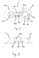
- Figure 2 shows a section of the connecting element according to the invention along the line A-A.
- Figure 3 shows a section of the connecting element according to the invention along the line B-B.
- Figure 4 shows a perspective view of the connecting element according to the invention.
- Figure 5 shows a perspective view of the basic parts of the primary generator to which a secondary generator is connected by way of a connecting element in accordance with the present invention, with the connecting element open in section to give a detailed view.
- Figure 1 shows a secondary generator GS with a combustion chamber connected to a primary generator GP at the top of which a connecting element 1 is fixed.
- first fuel generator GP with a helical heat exchanger 2 that has a finned tube 201 which is spirally wound to form an appropriate number of coils 202.
- the combustion products of the secondary generator GS hereinafter simply referred to as flue gases, are cooled using the heat exchanger 2 of the primary generator GP through the heat exchange with the thermal carrier fluid circulating inside it.
- the connecting element 1 has a channel 104 for cooling, using the same thermal carrier fluid of the primary generator GP, the head 3 of the secondary generator GS which is exposed to the high temperatures of the flue gases generated in its combustion chamber CC. According to the embodiment described in detail in figures 1 , 2 , 3 and 5 , said connecting element 1 also has a duct 105 for the flow of said flue gases from the secondary generator GS to the primary generator GP.
- Said channel 104 and said duct 105 have at least one shared wall 106 made of conductive material to allow heat exchange between said thermal carrier fluid flowing through said channel 104 and said flue gases flowing through said duct 105.
- Said heat exchange therefore allows the thermal carrier fluid to absorb part of the heat of the secondary generator GS flue gases when they flow through the duct 105 of the connecting element 1.
- the flue gases enter the heat exchanger 2 of the primary generator GP already partly cooled whereas the thermal carrier fluid exits said channel 104 with a higher temperature than the one when it entered because of the heat absorbed by the same flue gases and head 3 of the secondary generator GS.
- the heat exchange that takes place in said connecting element 1 leads to a significant increase in the efficiency and performance of the integrated generator GI.
- said connecting element 1 includes a passage 107 for entry of the secondary generator GS flue gases in the duct 105 and a passage 108 for discharge of the same flue gases from duct 105 to the heat exchanger 2 of the primary generator GP.
- 109 indicates a passage for the thermal carrier fluid of the primary generator GP connected to the end 203 of tube 201 of the heat exchanger 2 (see Figure 5 ).
- 110 indicates an exit end for the thermal carrier fluid from said channel 104 towards the heating system users, for example.
- said channel 104 for the thermal carrier fluid of the primary generator GP comprises a first branch 104.a and a second branch 104.b.
- Said first branch 104.a starts from said passage 109 and has a first curved section that surrounds part of said passage 108, a second intermediate section which is substantially straight and a third curved section that surrounds part of said passage 107, ensuring adequate cooling of head 3 of the secondary generator GS .
- said second branch 104.b then conveys the thermal carrier fluid from head 3 of the secondary generator GS to the exit end 110 placed next to said passage 109 and from which it is separated by partition 111.
- Duct 105 for the passing of flue gases from the secondary generator GS to the primary generator GP is comprised and enclosed between said first and second branch 104.a e 104.b.
- said channel 104 and duct 105 have a substantially rectangular section.
- Said connecting element 1 can be fastened with flanges 101 and 102 to the upper ends of the primary generator GP and the secondary generator GS.
- Said flanges 101 and 102 and said channel 104 and duct 105 form a single block obtained by aluminium die-casting.
- flanges 101 and 102 also serve as covers 101 and 102 of the heat exchanger 2 of the primary generator GP and the secondary generator GS.
- connecting element 1 can be devised by those skilled in art without departing from the scope and spirit of the invention and it is also clear that in the practical implementation of the invention, the various components previously described may be replaced by elements that are technically equivalent.
- the channel 104 for the passing of thermal carrier fluid from the primary generator GP to head 3 of the secondary generator GS is connected downstream of the heat exchanger 2 of said primary generator GP and sends said thermal carrier fluid to the users.
- said integrated generator GI having a primary generator GP which is not necessarily a fuel generator but one that is capable of heating a thermal carrier fluid.
- thermoelectric generators for example, as already used in the known state of the art but they may also consist of other heat engines such as absorption or compressor refrigerating systems (such as heat pumps) driven by an internal combustion engine.
Landscapes
- Engineering & Computer Science (AREA)
- Physics & Mathematics (AREA)
- Thermal Sciences (AREA)
- Chemical & Material Sciences (AREA)
- Combustion & Propulsion (AREA)
- Mechanical Engineering (AREA)
- General Engineering & Computer Science (AREA)
- Heat Treatment Of Water, Waste Water Or Sewage (AREA)
- Heat-Exchange Devices With Radiators And Conduit Assemblies (AREA)
Abstract
Description
- The present invention relates to a primary fuel generator such as a boiler for space and/or domestic water heating, hereinafter referred to as a primary generator, to which a secondary generator which is also a fuel generator is connected where this secondary generator may be a thermoelectric cogenerator such as a Stirling motor or a fuel cell. More specifically, the present invention relates to a means of cooling at least the head of the thermoelectric generator.
- The head of the thermoelectric generator indicates the area of the secondary generator immediately behind the combustion chamber which the combustion products that are generated in it flow through.
- The integration and combination of said primary generator with said secondary generator is hereinafter referred to as integrated generator GI.
- The use of fuel heat generator heat exchangers is useful for the heat absorption of combustion products of a thermoelectric generator.
- Systems in which the combustion products of a thermoelectric cogenerator are cooled in the heat exchangers of a primary generator together with its combustion products are already known.
- Document
WO 01/90656 - In document
GB 2 375 590 - In both solutions shown in the aforementioned documents, the high temperatures of the secondary generator flue gases may cause excessive, abnormal overheating of the principal parts of the thermoelectric generator and the duct conveying the flue gases and the areas and elements surrounding it.
- This problem has already been addressed in document
WO 2004/102081 which describes a secondary generator connected to a primary generator comprising a heat exchanger divided into two finned chambers for the cooling of the combustion products of both generators and surrounded by a third external chamber for the flowing of thermal carrier fluid with which said combustion products exchange. - With said system, part of said thermal carrier fluid can then be conveyed to a cooling circuit on the secondary generator.
- Cooling is restricted to the body of the secondary generator whereas, as is well known, the part of the secondary generator that undergoes the greatest thermal stress is the head, that is, the part immediately behind the combustion chamber and directly traversed by the flue gases generated in it.
- To eliminate the aforementioned limits, at least in part, a first aim of the present invention is to indicate a simplified means for cooling at least the head of the secondary generator with the same thermal carrier fluid of the primary generator.
- A second aim of the present invention is to develop a means of connection and entry of secondary generator flue gases in the heat exchanger of said primary generator for a primary generator connected to a secondary generator.
- Another aim of the present invention is that of reducing the heat loss by the combustion products of the secondary generator during transport and flow to the heat exchanger of the primary generator.
- These and further aims and advantages can be obtained using a connecting element as described below with the aid of illustrations in some of the preferred embodiments and in the enclosed claims which are an integral part of the description.
-
Figure 1 illustrates a vertical section of the basic parts of a primary generator to which a secondary generator is connected by way of a connecting element in accordance with the invention. -
Figure 2 shows a section of the connecting element according to the invention along the line A-A. -
Figure 3 shows a section of the connecting element according to the invention along the line B-B. -
Figure 4 shows a perspective view of the connecting element according to the invention. -
Figure 5 shows a perspective view of the basic parts of the primary generator to which a secondary generator is connected by way of a connecting element in accordance with the present invention, with the connecting element open in section to give a detailed view. -
Figure 1 shows a secondary generator GS with a combustion chamber connected to a primary generator GP at the top of which a connectingelement 1 is fixed. - The embodiment of the invention that is described below shows since it is a preferred embodiment a first fuel generator GP with a helical heat exchanger 2 that has a finned tube 201 which is spirally wound to form an appropriate number of coils 202.
- The combustion products of the secondary generator GS, hereinafter simply referred to as flue gases, are cooled using the heat exchanger 2 of the primary generator GP through the heat exchange with the thermal carrier fluid circulating inside it.
- The connecting
element 1 has achannel 104 for cooling, using the same thermal carrier fluid of the primary generator GP, thehead 3 of the secondary generator GS which is exposed to the high temperatures of the flue gases generated in its combustion chamber CC. According to the embodiment described in detail infigures 1 ,2 ,3 and5 , said connectingelement 1 also has aduct 105 for the flow of said flue gases from the secondary generator GS to the primary generator GP. - Said
channel 104 and saidduct 105 have at least one sharedwall 106 made of conductive material to allow heat exchange between said thermal carrier fluid flowing through saidchannel 104 and said flue gases flowing through saidduct 105. - Said heat exchange therefore allows the thermal carrier fluid to absorb part of the heat of the secondary generator GS flue gases when they flow through the
duct 105 of the connectingelement 1. - As a result, the flue gases enter the heat exchanger 2 of the primary generator GP already partly cooled whereas the thermal carrier fluid exits said
channel 104 with a higher temperature than the one when it entered because of the heat absorbed by the same flue gases andhead 3 of the secondary generator GS. - The heat exchange that takes place in said connecting
element 1 leads to a significant increase in the efficiency and performance of the integrated generator GI. - As shown in
figures 2 and5 , said connectingelement 1 includes apassage 107 for entry of the secondary generator GS flue gases in theduct 105 and apassage 108 for discharge of the same flue gases fromduct 105 to the heat exchanger 2 of the primary generator GP. - Similarly, 109 indicates a passage for the thermal carrier fluid of the primary generator GP connected to the
end 203 of tube 201 of the heat exchanger 2 (seeFigure 5 ). - Finally, 110 indicates an exit end for the thermal carrier fluid from said
channel 104 towards the heating system users, for example. - More specifically, and with reference to
figures 2, 3 and5 , it should be noted how saidchannel 104 for the thermal carrier fluid of the primary generator GP comprises a first branch 104.a and a second branch 104.b. - Said first branch 104.a starts from said
passage 109 and has a first curved section that surrounds part of saidpassage 108, a second intermediate section which is substantially straight and a third curved section that surrounds part of saidpassage 107, ensuring adequate cooling ofhead 3 of the secondary generator GS . - According to a course that is substantially the reverse of the previous one, said second branch 104.b then conveys the thermal carrier fluid from
head 3 of the secondary generator GS to theexit end 110 placed next to saidpassage 109 and from which it is separated bypartition 111. -
Duct 105 for the passing of flue gases from the secondary generator GS to the primary generator GP is comprised and enclosed between said first and second branch 104.a e 104.b. - According to a preferred embodiment which is however not limited to the present invention, said
channel 104 andduct 105 have a substantially rectangular section. - Said connecting
element 1 can be fastened withflanges - Said
flanges channel 104 andduct 105 form a single block obtained by aluminium die-casting. - In addition,
flanges - It is clear that numerous embodiments of the connecting
element 1 can be devised by those skilled in art without departing from the scope and spirit of the invention and it is also clear that in the practical implementation of the invention, the various components previously described may be replaced by elements that are technically equivalent. - For example, as already set forth in the foregoing description, the
channel 104 for the passing of thermal carrier fluid from the primary generator GP tohead 3 of the secondary generator GS is connected downstream of the heat exchanger 2 of said primary generator GP and sends said thermal carrier fluid to the users. - However, there is nothing to prevent said
channel 104 being connected upstream of the same heat exchanger 2 or in an intermediate area in series with the heat exchanger 2. - Furthermore, there is nothing to prevent said integrated generator GI having a primary generator GP which is not necessarily a fuel generator but one that is capable of heating a thermal carrier fluid.
- Finally, as an example of second heat generators only thermoelectric generators have been mentioned, a thermoelectric cogenerator, for example, as already used in the known state of the art but they may also consist of other heat engines such as absorption or compressor refrigerating systems (such as heat pumps) driven by an internal combustion engine.
Claims (17)
- Integrated generator (GI) comprising a primary generator (GP) and a secondary generator (GS) with a combustion chamber (CC), said secondary generator (GS) being partially cooled by the thermal carrier fluid of said primary generator (GP) circulating in a channel (104, 104.a, 104.b)
characterized in that
said thermal carrier fluid of the primary generator (GP) cools at least the head (3) of said secondary generator (GS). - Integrated generator (GI) as in the previous claim
characterized in that- said primary generator (GP) is a fuel generator with a heat exchanger (2) to which also the combustion products of the secondary generator (GS) transfer heat- said secondary generator (GS) discharges said combustion products in said heat exchanger (2) of said primary generator (GP) through a duct (105). - Integrated generator (GI) as in claim 1 or 2
characterized in that
said combustion products flowing through said duct (105) are cooled by the thermal carrier fluid of said primary generator (GP) that flows in said channel (104). - Connecting element (1) for integrated generator (GI) as in claim 1 at least
characterized in that
it comprises channels (104, 104.a) suitable for cooling at least the head (3) of said secondary generator (GS), said channels (104, 104.a) being traversed by the thermal carrier fluid of the primary generator (GP). - Connecting element (1) for integrated generator (GI) as in the previous claim
characterized in that
it further comprises a duct (105) for the flowing of the combustion products of the secondary generator (GS) from said secondary generator (GS) to said primary generator (GP). - Connecting element (1) for integrated generator (GI) as in claim 4 or 5
characterized in that
means of heat exchange (106) between the combustion products flowing through said duct (105) and the thermal carrier fluid flowing through said channel (104, 104.a, 104.b) are included. - Connecting element (1) for integrated generator (GI) as in the previous claim
characterized in that
said means of heat exchange (106) is a wall (106) shared by said channel (104, 104.b, 104.b) and said duct (105). - Connecting element (1) for integrated generators (GI) as in claim 4 at least
characterized in that
said channel (104, 104.a, 104.b) includes a first branch (104.a) and a second branch (104.b), said first branch (104.a) being able to convey the thermal carrier fluid from the primary generator (GP) to the head (3) of the secondary generator (GS), and said second branch (104.b) being able to convey the thermal carrier fluid from said head (3) of said secondary generator (GS) to an exit end (110) towards the users. - Connecting element (1) for integrated generator (GI) as in the previous claim
characterized in that
said first branch (104.a):- begins at the passage (109) for the thermal carrier fluid connected to the end (203) of the tube (201) of the heat exchanger (2) of said primary generator (GP)- comprises a first curved section that surrounds part of the passage (108) for the discharge of said combustion products from the duct (105) inside said heat exchanger (2), a second intermediate straight section and a third curved section that surrounds part of the passage (107) for the entry of said combustion products in said duct (105),while said second branch (104.b) following a course that is substantially the reverse of said first branch (104.a) and terminating in said discharge end (110) situated near said passage (109) from which it is divided by a partition (111). - Connecting element (1) for integrated generator (GI) as in any previous claim from 4 onwards
characterized in that
said duct (105) is comprised and enclosed between said first branch (104.a) and
said second branch (104.b) of said channel (104). - Connecting element (1) for integrated generator (GI) as in any previous claim
characterized in that
said channel (104) and said duct (105) have a substantially rectangular section. - Connecting element (1) for integrated generator (GI) as in any previous claim
characterized by
being connected by flanges (101, 102) to the upper ends of the primary generator (GP) and the secondary generator (GS), said flanges (101, 102) also serving as covers (101, 102) for said primary generator (GP) and said secondary generator (GS). - Connecting element (1) for integrated generator (GI) as in any previous claim from 4 onwards
characterized in that
said flanges (101, 102) and said channel (104) and duct (105) form a single block. - Connecting element (1) for integrated generator (GI) as in any previous claim
characterized by
being obtained by aluminium die-casting. - Integrated generator (GI) as in any previous claim
characterized in that
said second heat generator (GS) is a thermoelectric generator. - Integrated generator (GI) as in the previous claim
characterized in that
said thermoelectric generator (GS) is a Stirling motor or a fuel cell. - Integrated generator (GI) as in claim 1 at least
characterized in that
said secondary generator (GS) is an absorption or compressor refrigerating system or heat pump driven by an internal combustion engine.
Applications Claiming Priority (1)
| Application Number | Priority Date | Filing Date | Title |
|---|---|---|---|
| IT000002A ITAN20070002A1 (en) | 2007-01-12 | 2007-01-12 | COOLED CONNECTION ORGAN FOR THE COMBINATION OF MORE HEAT GENERATORS. |
Publications (2)
| Publication Number | Publication Date |
|---|---|
| EP1944560A2 true EP1944560A2 (en) | 2008-07-16 |
| EP1944560A3 EP1944560A3 (en) | 2013-06-05 |
Family
ID=39365906
Family Applications (1)
| Application Number | Title | Priority Date | Filing Date |
|---|---|---|---|
| EP07023701.1A Withdrawn EP1944560A3 (en) | 2007-01-12 | 2007-12-07 | Cooled connecting element for combination of several heat generators |
Country Status (2)
| Country | Link |
|---|---|
| EP (1) | EP1944560A3 (en) |
| IT (1) | ITAN20070002A1 (en) |
Cited By (1)
| Publication number | Priority date | Publication date | Assignee | Title |
|---|---|---|---|---|
| EP2467651A4 (en) * | 2009-08-18 | 2014-04-23 | Intellihot Inc | SERPENTINE TUBE HEAT EXCHANGER FOR HOT WATER CIRCUIT WITHOUT TANK |
Citations (3)
| Publication number | Priority date | Publication date | Assignee | Title |
|---|---|---|---|---|
| WO2001090656A1 (en) | 2000-05-26 | 2001-11-29 | Enatec Micro-Cogen B.V. | Apparatus and method for combined generation of heat and electricity |
| GB2375590A (en) | 2001-03-16 | 2002-11-20 | Bosch Gmbh Robert | Device for heating water and generating electrical energy |
| WO2004102081A1 (en) | 2003-05-13 | 2004-11-25 | Microgen Energy Limited | A heating arrangement |
Family Cites Families (2)
| Publication number | Priority date | Publication date | Assignee | Title |
|---|---|---|---|---|
| US2121537A (en) * | 1932-12-29 | 1938-06-21 | Alco Products Inc | Furnace construction |
| DE19943613B4 (en) * | 1999-09-11 | 2006-09-07 | Robert Bosch Gmbh | Heating system for heat and power generation |
-
2007
- 2007-01-12 IT IT000002A patent/ITAN20070002A1/en unknown
- 2007-12-07 EP EP07023701.1A patent/EP1944560A3/en not_active Withdrawn
Patent Citations (3)
| Publication number | Priority date | Publication date | Assignee | Title |
|---|---|---|---|---|
| WO2001090656A1 (en) | 2000-05-26 | 2001-11-29 | Enatec Micro-Cogen B.V. | Apparatus and method for combined generation of heat and electricity |
| GB2375590A (en) | 2001-03-16 | 2002-11-20 | Bosch Gmbh Robert | Device for heating water and generating electrical energy |
| WO2004102081A1 (en) | 2003-05-13 | 2004-11-25 | Microgen Energy Limited | A heating arrangement |
Cited By (1)
| Publication number | Priority date | Publication date | Assignee | Title |
|---|---|---|---|---|
| EP2467651A4 (en) * | 2009-08-18 | 2014-04-23 | Intellihot Inc | SERPENTINE TUBE HEAT EXCHANGER FOR HOT WATER CIRCUIT WITHOUT TANK |
Also Published As
| Publication number | Publication date |
|---|---|
| ITAN20070002A1 (en) | 2008-07-13 |
| EP1944560A3 (en) | 2013-06-05 |
Similar Documents
| Publication | Publication Date | Title |
|---|---|---|
| US8739521B2 (en) | Cogeneration apparatus | |
| EP0128198B1 (en) | Combustion product condensing water heater | |
| KR100322802B1 (en) | Vehicle cooling system and its liquid cooling capacitor | |
| US7216696B2 (en) | External flue heat exchangers | |
| CN101395433B (en) | Single tank combined heat source machine | |
| EP2037200A2 (en) | Composite heat exchanger | |
| US6749014B2 (en) | External flue heat exchangers | |
| CA2127923C (en) | High efficiency fuel-fired condensing furnace having a compact heat exchanger system | |
| EP1944560A2 (en) | Cooled connecting element for combination of several heat generators | |
| WO2011117907A2 (en) | Heat exchanger | |
| CN111148961B (en) | Exhaust gas heat exchanger | |
| KR20060006962A (en) | Fuel cooling unit with thin inner structure for connection to air conditioners | |
| US6296480B1 (en) | Circulating oil heater | |
| RU2137049C1 (en) | Hot-water boiler | |
| EP1936287A2 (en) | Combustion unit for heat generator to which an additional heat generator is connected | |
| US3895607A (en) | Fire tube furnace | |
| CN102666160B (en) | For the heat exchanger of portable heating arrangement, portable heating arrangement and self-propelled vehicle | |
| EP0759527A1 (en) | Heat exchanger | |
| EP1975533A2 (en) | Heat exchanger and condensing boiler incorporating a heat exchanger | |
| EP3808954A1 (en) | Heat exchanger plate for thermal insulation | |
| KR100417209B1 (en) | Heat exchanger of gas boiler | |
| CN211397739U (en) | EGR cooler | |
| CA2144493C (en) | High efficiency fuel-fired condensing furnace having a compact heat exchanger system | |
| US20150053152A1 (en) | Boiler with integrated economizer | |
| PL242434B1 (en) | Combination heating boiler |
Legal Events
| Date | Code | Title | Description |
|---|---|---|---|
| PUAI | Public reference made under article 153(3) epc to a published international application that has entered the european phase |
Free format text: ORIGINAL CODE: 0009012 |
|
| AK | Designated contracting states |
Kind code of ref document: A2 Designated state(s): AT BE BG CH CY CZ DE DK EE ES FI FR GB GR HU IE IS IT LI LT LU LV MC MT NL PL PT RO SE SI SK TR |
|
| AX | Request for extension of the european patent |
Extension state: AL BA HR MK RS |
|
| RAP1 | Party data changed (applicant data changed or rights of an application transferred) |
Owner name: ARISTON THERMO S.P.A. |
|
| PUAL | Search report despatched |
Free format text: ORIGINAL CODE: 0009013 |
|
| AK | Designated contracting states |
Kind code of ref document: A3 Designated state(s): AT BE BG CH CY CZ DE DK EE ES FI FR GB GR HU IE IS IT LI LT LU LV MC MT NL PL PT RO SE SI SK TR |
|
| AX | Request for extension of the european patent |
Extension state: AL BA HR MK RS |
|
| RIC1 | Information provided on ipc code assigned before grant |
Ipc: F24H 1/43 20060101AFI20130429BHEP Ipc: F02G 1/055 20060101ALI20130429BHEP Ipc: F24H 9/14 20060101ALI20130429BHEP |
|
| AKY | No designation fees paid | ||
| REG | Reference to a national code |
Ref country code: DE Ref legal event code: R108 |
|
| REG | Reference to a national code |
Ref country code: DE Ref legal event code: R108 Effective date: 20140212 |
|
| STAA | Information on the status of an ep patent application or granted ep patent |
Free format text: STATUS: THE APPLICATION IS DEEMED TO BE WITHDRAWN |
|
| 18D | Application deemed to be withdrawn |
Effective date: 20131206 |