EP1944545A2 - Gas manifold for a cooking range with an emergency tap - Google Patents
Gas manifold for a cooking range with an emergency tap Download PDFInfo
- Publication number
- EP1944545A2 EP1944545A2 EP20070380376 EP07380376A EP1944545A2 EP 1944545 A2 EP1944545 A2 EP 1944545A2 EP 20070380376 EP20070380376 EP 20070380376 EP 07380376 A EP07380376 A EP 07380376A EP 1944545 A2 EP1944545 A2 EP 1944545A2
- Authority
- EP
- European Patent Office
- Prior art keywords
- gas manifold
- conduit
- gas
- distributor conduit
- segment
- Prior art date
- Legal status (The legal status is an assumption and is not a legal conclusion. Google has not performed a legal analysis and makes no representation as to the accuracy of the status listed.)
- Withdrawn
Links
- 238000010411 cooking Methods 0.000 title claims abstract description 15
- 238000007789 sealing Methods 0.000 claims abstract description 14
- 239000000463 material Substances 0.000 claims description 3
- 230000002093 peripheral effect Effects 0.000 claims 1
- XAGFODPZIPBFFR-UHFFFAOYSA-N aluminium Chemical compound [Al] XAGFODPZIPBFFR-UHFFFAOYSA-N 0.000 description 1
- 229910052782 aluminium Inorganic materials 0.000 description 1
- 239000004411 aluminium Substances 0.000 description 1
- 230000037431 insertion Effects 0.000 description 1
- 238000003780 insertion Methods 0.000 description 1
- 238000009434 installation Methods 0.000 description 1
- 238000011144 upstream manufacturing Methods 0.000 description 1
Images
Classifications
-
- F—MECHANICAL ENGINEERING; LIGHTING; HEATING; WEAPONS; BLASTING
- F17—STORING OR DISTRIBUTING GASES OR LIQUIDS
- F17D—PIPE-LINE SYSTEMS; PIPE-LINES
- F17D5/00—Protection or supervision of installations
- F17D5/005—Protection or supervision of installations of gas pipelines, e.g. alarm
-
- F—MECHANICAL ENGINEERING; LIGHTING; HEATING; WEAPONS; BLASTING
- F23—COMBUSTION APPARATUS; COMBUSTION PROCESSES
- F23K—FEEDING FUEL TO COMBUSTION APPARATUS
- F23K5/00—Feeding or distributing other fuel to combustion apparatus
- F23K5/002—Gaseous fuel
- F23K5/005—Gaseous fuel from a central source to a plurality of burners
-
- F—MECHANICAL ENGINEERING; LIGHTING; HEATING; WEAPONS; BLASTING
- F23—COMBUSTION APPARATUS; COMBUSTION PROCESSES
- F23K—FEEDING FUEL TO COMBUSTION APPARATUS
- F23K5/00—Feeding or distributing other fuel to combustion apparatus
- F23K5/002—Gaseous fuel
- F23K5/007—Details
-
- F—MECHANICAL ENGINEERING; LIGHTING; HEATING; WEAPONS; BLASTING
- F24—HEATING; RANGES; VENTILATING
- F24C—DOMESTIC STOVES OR RANGES ; DETAILS OF DOMESTIC STOVES OR RANGES, OF GENERAL APPLICATION
- F24C15/00—Details
- F24C15/36—Protective guards, e.g. for preventing access to heated parts
-
- F—MECHANICAL ENGINEERING; LIGHTING; HEATING; WEAPONS; BLASTING
- F24—HEATING; RANGES; VENTILATING
- F24C—DOMESTIC STOVES OR RANGES ; DETAILS OF DOMESTIC STOVES OR RANGES, OF GENERAL APPLICATION
- F24C3/00—Stoves or ranges for gaseous fuels
- F24C3/12—Arrangement or mounting of control or safety devices
- F24C3/126—Arrangement or mounting of control or safety devices on ranges
-
- F—MECHANICAL ENGINEERING; LIGHTING; HEATING; WEAPONS; BLASTING
- F23—COMBUSTION APPARATUS; COMBUSTION PROCESSES
- F23K—FEEDING FUEL TO COMBUSTION APPARATUS
- F23K2900/00—Special features of, or arrangements for fuel supplies
- F23K2900/05001—Control or safety devices in gaseous or liquid fuel supply lines
-
- F—MECHANICAL ENGINEERING; LIGHTING; HEATING; WEAPONS; BLASTING
- F23—COMBUSTION APPARATUS; COMBUSTION PROCESSES
- F23K—FEEDING FUEL TO COMBUSTION APPARATUS
- F23K2900/00—Special features of, or arrangements for fuel supplies
- F23K2900/05002—Valves for gaseous fuel supply lines
-
- F—MECHANICAL ENGINEERING; LIGHTING; HEATING; WEAPONS; BLASTING
- F23—COMBUSTION APPARATUS; COMBUSTION PROCESSES
- F23N—REGULATING OR CONTROLLING COMBUSTION
- F23N2235/00—Valves, nozzles or pumps
- F23N2235/12—Fuel valves
- F23N2235/24—Valve details
-
- Y—GENERAL TAGGING OF NEW TECHNOLOGICAL DEVELOPMENTS; GENERAL TAGGING OF CROSS-SECTIONAL TECHNOLOGIES SPANNING OVER SEVERAL SECTIONS OF THE IPC; TECHNICAL SUBJECTS COVERED BY FORMER USPC CROSS-REFERENCE ART COLLECTIONS [XRACs] AND DIGESTS
- Y10—TECHNICAL SUBJECTS COVERED BY FORMER USPC
- Y10T—TECHNICAL SUBJECTS COVERED BY FORMER US CLASSIFICATION
- Y10T137/00—Fluid handling
- Y10T137/8593—Systems
- Y10T137/85938—Non-valved flow dividers
-
- Y—GENERAL TAGGING OF NEW TECHNOLOGICAL DEVELOPMENTS; GENERAL TAGGING OF CROSS-SECTIONAL TECHNOLOGIES SPANNING OVER SEVERAL SECTIONS OF THE IPC; TECHNICAL SUBJECTS COVERED BY FORMER USPC CROSS-REFERENCE ART COLLECTIONS [XRACs] AND DIGESTS
- Y10—TECHNICAL SUBJECTS COVERED BY FORMER USPC
- Y10T—TECHNICAL SUBJECTS COVERED BY FORMER US CLASSIFICATION
- Y10T137/00—Fluid handling
- Y10T137/8593—Systems
- Y10T137/87265—Dividing into parallel flow paths with recombining
-
- Y—GENERAL TAGGING OF NEW TECHNOLOGICAL DEVELOPMENTS; GENERAL TAGGING OF CROSS-SECTIONAL TECHNOLOGIES SPANNING OVER SEVERAL SECTIONS OF THE IPC; TECHNICAL SUBJECTS COVERED BY FORMER USPC CROSS-REFERENCE ART COLLECTIONS [XRACs] AND DIGESTS
- Y10—TECHNICAL SUBJECTS COVERED BY FORMER USPC
- Y10T—TECHNICAL SUBJECTS COVERED BY FORMER US CLASSIFICATION
- Y10T137/00—Fluid handling
- Y10T137/8593—Systems
- Y10T137/87265—Dividing into parallel flow paths with recombining
- Y10T137/87338—Flow passage with bypass
Definitions
- the present invention relates to the supply of gas to a domestic cooking device by means of a gas manifold fitted with a number of regulation taps of an individual gas flow assembled on a distributor conduit, and of an emergency valve connected at the inlet of the gas manifold.
- a gas manifold of the aforementioned type is known, fitted with a plurality of manual regulation taps assembled along a distributor conduit, such as that disclosed in US-5979430 for a cooking device, in which the end of the inlet of the distributor conduit has a cylindrical cross-section and is directly connected to a gas outlet of the cooking device.
- a gas manifold with an emergency valve disposed at the inlet of the distributor conduit in order to interrupt the passage of gas by means of an emergency button is also known, as disclosed in US-5694916 or in US-6289792 .
- These emergency valves are connected in series with the distributor conduit, and their valve member is intercalated in the distributor conduit. Further, these emergency valves are of the electrically operated type.
- US-4709687 discloses a safety valve for a gas manifold to a cooking range, which has a button operated by the cooking range cover. This manual safety valve is assembled on an auxiliary segment of the conduit, which is connected in series with the inlet of the distributor conduit.
- the object of the invention is to provide a gas manifold fitted with a number of manual regulation taps assembled on a long distributor conduit of the gas flow to a cooking device, and provided with an emergency tap or valve assembled on the distributor conduit with a cut-off valve in parallel to the conduit, as a result of which the inlet flow is diverted towards the emergency tap with the distributor conduit being closed between the inlet and outlet of the cut-off valve by means of an airtight seal device.
- An emergency tap connected in parallel to the distributor conduit has advantages over the taps in the prior art, in which the cut-off valve is intercalated in the distributor conduit itself.
- the manual emergency tap connected in parallel to the distributor conduit is inexpensive due to its simple operation and its simple connection outside the gas pipe.
- In order to install an emergency tap that cuts the gas flow at the inlet of the distributor conduit it is necessary to intercalate an airtight seal in the interior of the distributor conduit so that all the inlet flow is diverted towards the emergency tap, thereby bypassing said airtight seal.
- the airtight seal in the gas inlet comprises a simple device that is incorporated on one end of the same distributor conduit, before being bent or twisted so that it can be fitted to the regulation taps and the cooking range.
- the seal device comprises a circular disc made of a deformable material and provided with a ring sealing gasket that expands diametrically with the disc to close permanently against the internal wall of the distributor conduit.
- an embodiment of the gas manifold 1 comprises a long distributor conduit 2 of a gas flow Q made of a cylindrical pipe, which is connected at one end to an outlet 6 of the gas source in a cooking device, a plurality of regulation taps 3 for the flow Q, preferably of the rotary type assembled on the conduit 2, a tap or emergency valve 4 of the type operated manually by means of an emergency button 5 that comprises a cut-off valve 10 connected in parallel to a segment 22 of the distributor conduit 2, and an internal airtight seal device 13 of the distributor conduit 2 intercalated in the interior of said segment of conduit 22, between the inlet 8 and the outlet 9 of the emergency tap.
- the segment of conduit 22 bearing the emergency tap 4 is followed by the conduit end 21 that is connected to the gas outlet 6 of the cooking range.
- the button 5 is adapted in order to operate the cut-off valve 10 suddenly and thus shut off the inlet of flow Q.
- the regulation taps 3 are assembled spaced apart from each other on a long segment 23 upstream from the distributor conduit 2, and each of them connected in parallel in relation to the flow Q of gas.
- the passage of the inlet flow Q in the manifold 1 is established first of all through the emergency tap 4, extending beyond the airtight seal device 13 and passing through the distributor segment 23 of the conduit.
- the tubular segment of the conduit 2 incorporates the seal device 13 in its interior, formed by a deformable seal disc 14 and a ring sealing gasket 15.
- the seal disc 14 has a cylindrical edge 14c with a width W, on which a V-shaped radial groove 16 is formed for housing and guiding a ring sealing gasket 15.
- the seal device 13 is incorporated in the interior of the distributor conduit 2, of a specific diameter D1, in an initial operation, before being connected to the gas outlet 6 of the appliance, and also before the conduit 2 is bent.
- the initial diameter of the seal device 13 is smaller or similar to that of the internal wall 22a of the intermediate segment of the pipe.
- the end 21 of the pipe for the gas outlet 6 and the intermediate segment 22 of the pipe for the installation of the emergency tap 4 and the seal device 13 may be part of the same cylindrical conduit 2, with equal diameters D1 between them.
- the diameter D2 of the deformed disc 14 is smaller than the interior diameter D1 of the conduit 2, in a sufficient proportion to create a space of expansion for the disc 14 and the sealing gasket 15.
- the seal disc 14 is made of a material that is deformable with an axial pressure, such as aluminium, and has a first pressure base 14a and a second pressure base 14b, through which the deformation causes the diametrical expansion up to a specific diameter, somewhat smaller or similar to that of the internal diameter D1.
- the ring sealing gasket 15 expands more than the diameter D1 of the internal wall 22a of the pipe, thereby forming a permanent airtight seal beneath the emergency cut-off valve 10.
- a deformation device for example with two pistons, is used, the axial force of which is exerted on both pressure bases 14a and 14b, the deformation device subsequently being removed.
- the V-shaped groove 16 on the disc guides the ring sealing gasket 15 and holds it in place when the disc 14 is deformed, and at the same time pushes the ring sealing gasket 15 against the internal wall 22a of the pipe.
- Figure 3 shows a second embodiment of the seal disc 14.
- the disc seal 14 comprises a cylindrical edge 14c as well, in which a V-shaped radial groove 16 is formed, for the housing and guiding of a ring sealing gasket, not shown in figure 3 .
- the seal disc 14 comprises, on both sides of said radial groove 16, respective cylindrical segments 17 and 18 of different width and a diameter D2, the respective bases of said cylindrical segments 17 and 18 forming the pressure bases 14a and 14b.
- the width W1 of the cylindrical segment 17 is substantially bigger than the width W2 of the cylindrical segment 18 and also bigger than the maximum width of the radial groove 16.
- the fact that the cylindrical segment 17 has this width W1 makes the insertion of the seal disc 14 in the distributor conduit 2 be easier during the assembly, because it allows the guiding of said seal disc 14 in the interior of the distributor conduit 2. Further, it also makes the application of the axial force by means of a deformation device easier.
- the pressure base 14a of the cylindrical segment 17 is substantially flat, and the pressure base 14b of the cylindrical segment 18 comprises a cone shaped cavity 19.
- a first piston with a flat surface is supported on the flat surface of the pressure base 14a, and a second piston with a conical end pressures on the cavity 19 of the base 14b, the seal disc 14 getting deformed and obtaining the sealing.
- the cavity 19 allows centring the piston and contributes to have less thickness in the part of the seal disc 14 that gets deformed by means of the axial force exerted by the second piston.
- the width W2 of the cylindrical segment 18 is substantially smaller than the maximum width of the radial groove 16.
- the width W1 of the cylindrical segment 17 is approximately five times bigger than the width W2 of the cylindrical segment 18.
Landscapes
- Engineering & Computer Science (AREA)
- Mechanical Engineering (AREA)
- General Engineering & Computer Science (AREA)
- Chemical & Material Sciences (AREA)
- Combustion & Propulsion (AREA)
- Feeding And Controlling Fuel (AREA)
- Lift Valve (AREA)
Abstract
Description
- The present invention relates to the supply of gas to a domestic cooking device by means of a gas manifold fitted with a number of regulation taps of an individual gas flow assembled on a distributor conduit, and of an emergency valve connected at the inlet of the gas manifold.
- A gas manifold of the aforementioned type is known, fitted with a plurality of manual regulation taps assembled along a distributor conduit, such as that disclosed in
US-5979430 for a cooking device, in which the end of the inlet of the distributor conduit has a cylindrical cross-section and is directly connected to a gas outlet of the cooking device. - A gas manifold with an emergency valve disposed at the inlet of the distributor conduit in order to interrupt the passage of gas by means of an emergency button is also known, as disclosed in
US-5694916 or inUS-6289792 . These emergency valves are connected in series with the distributor conduit, and their valve member is intercalated in the distributor conduit. Further, these emergency valves are of the electrically operated type. -
US-4709687 discloses a safety valve for a gas manifold to a cooking range, which has a button operated by the cooking range cover. This manual safety valve is assembled on an auxiliary segment of the conduit, which is connected in series with the inlet of the distributor conduit. - The object of the invention is to provide a gas manifold fitted with a number of manual regulation taps assembled on a long distributor conduit of the gas flow to a cooking device, and provided with an emergency tap or valve assembled on the distributor conduit with a cut-off valve in parallel to the conduit, as a result of which the inlet flow is diverted towards the emergency tap with the distributor conduit being closed between the inlet and outlet of the cut-off valve by means of an airtight seal device.
- An emergency tap connected in parallel to the distributor conduit has advantages over the taps in the prior art, in which the cut-off valve is intercalated in the distributor conduit itself. The manual emergency tap connected in parallel to the distributor conduit, is inexpensive due to its simple operation and its simple connection outside the gas pipe. In order to install an emergency tap that cuts the gas flow at the inlet of the distributor conduit, it is necessary to intercalate an airtight seal in the interior of the distributor conduit so that all the inlet flow is diverted towards the emergency tap, thereby bypassing said airtight seal.
- The airtight seal in the gas inlet comprises a simple device that is incorporated on one end of the same distributor conduit, before being bent or twisted so that it can be fitted to the regulation taps and the cooking range. The seal device comprises a circular disc made of a deformable material and provided with a ring sealing gasket that expands diametrically with the disc to close permanently against the internal wall of the distributor conduit.
-
-
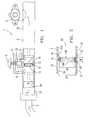
Figure 1 is a view of a gas manifold for a cooking device showing, in a partial section, an emergency valve at the inlet of the distributor conduit. -
Figure 2 is a view in detail of the gas inlet in the gas manifold offigure 1 showing a device with a seal device with a seal disc according to a first embodiment of the invention. -
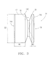
Figure 3 is a side view of a seal disc according to a second embodiment of the invention. - In reference to
figures 1 and 2 , an embodiment of the gas manifold 1 comprises along distributor conduit 2 of a gas flow Q made of a cylindrical pipe, which is connected at one end to anoutlet 6 of the gas source in a cooking device, a plurality ofregulation taps 3 for the flow Q, preferably of the rotary type assembled on theconduit 2, a tap oremergency valve 4 of the type operated manually by means of an emergency button 5 that comprises a cut-offvalve 10 connected in parallel to asegment 22 of thedistributor conduit 2, and an internalairtight seal device 13 of thedistributor conduit 2 intercalated in the interior of said segment ofconduit 22, between theinlet 8 and theoutlet 9 of the emergency tap. - The segment of
conduit 22 bearing theemergency tap 4 is followed by theconduit end 21 that is connected to thegas outlet 6 of the cooking range. The button 5 is adapted in order to operate the cut-offvalve 10 suddenly and thus shut off the inlet of flow Q. Theregulation taps 3 are assembled spaced apart from each other on along segment 23 upstream from thedistributor conduit 2, and each of them connected in parallel in relation to the flow Q of gas. - The passage of the inlet flow Q in the manifold 1 is established first of all through the
emergency tap 4, extending beyond theairtight seal device 13 and passing through thedistributor segment 23 of the conduit. - In reference to
figure 2 , the tubular segment of theconduit 2 incorporates theseal device 13 in its interior, formed by adeformable seal disc 14 and aring sealing gasket 15. In a first embodiment, shown in saidfigure 2 , theseal disc 14 has a cylindrical edge 14c with a width W, on which a V-shapedradial groove 16 is formed for housing and guiding aring sealing gasket 15. Theseal device 13 is incorporated in the interior of thedistributor conduit 2, of a specific diameter D1, in an initial operation, before being connected to thegas outlet 6 of the appliance, and also before theconduit 2 is bent. - In order to be introduced in the
intermediate segment 22a of the pipe, the initial diameter of theseal device 13 is smaller or similar to that of theinternal wall 22a of the intermediate segment of the pipe. Thus, theend 21 of the pipe for thegas outlet 6 and theintermediate segment 22 of the pipe for the installation of theemergency tap 4 and theseal device 13 may be part of the samecylindrical conduit 2, with equal diameters D1 between them. The diameter D2 of thedeformed disc 14 is smaller than the interior diameter D1 of theconduit 2, in a sufficient proportion to create a space of expansion for thedisc 14 and the sealinggasket 15. - The
seal disc 14 is made of a material that is deformable with an axial pressure, such as aluminium, and has afirst pressure base 14a and asecond pressure base 14b, through which the deformation causes the diametrical expansion up to a specific diameter, somewhat smaller or similar to that of the internal diameter D1. - As a result of the expansion of the
disc 14, thering sealing gasket 15 expands more than the diameter D1 of theinternal wall 22a of the pipe, thereby forming a permanent airtight seal beneath the emergency cut-offvalve 10. In order to deform theseal disc 14 and cause its diametrical expansion, a deformation device, for example with two pistons, is used, the axial force of which is exerted on bothpressure bases - The V-
shaped groove 16 on the disc guides thering sealing gasket 15 and holds it in place when thedisc 14 is deformed, and at the same time pushes thering sealing gasket 15 against theinternal wall 22a of the pipe. -
Figure 3 shows a second embodiment of theseal disc 14. In this second embodiment, thedisc seal 14 comprises a cylindrical edge 14c as well, in which a V-shapedradial groove 16 is formed, for the housing and guiding of a ring sealing gasket, not shown infigure 3 . Theseal disc 14 comprises, on both sides of saidradial groove 16, respectivecylindrical segments cylindrical segments pressure bases - As shown in
figure 3 , the width W1 of thecylindrical segment 17 is substantially bigger than the width W2 of thecylindrical segment 18 and also bigger than the maximum width of theradial groove 16. The fact that thecylindrical segment 17 has this width W1 makes the insertion of theseal disc 14 in thedistributor conduit 2 be easier during the assembly, because it allows the guiding of saidseal disc 14 in the interior of thedistributor conduit 2. Further, it also makes the application of the axial force by means of a deformation device easier. - The
pressure base 14a of thecylindrical segment 17 is substantially flat, and thepressure base 14b of thecylindrical segment 18 comprises a coneshaped cavity 19. During the assembly, a first piston with a flat surface is supported on the flat surface of thepressure base 14a, and a second piston with a conical end pressures on thecavity 19 of thebase 14b, theseal disc 14 getting deformed and obtaining the sealing. Thecavity 19 allows centring the piston and contributes to have less thickness in the part of theseal disc 14 that gets deformed by means of the axial force exerted by the second piston. The width W2 of thecylindrical segment 18 is substantially smaller than the maximum width of theradial groove 16. - In the embodiment shown in
figure 3 , the width W1 of thecylindrical segment 17 is approximately five times bigger than the width W2 of thecylindrical segment 18.
Claims (9)
- A gas manifold for a cooking device, of the type that includes a distributor conduit (2) made by a cylindrical pipe of a certain diameter (D1) fitted with a plurality of regulation taps (3) for the supply of a gas flow (Q) to the cooking device, wherein one inlet end (21) to the distributor conduit (2) is connected to a gas outlet (6) of the cooking device,
characterised in that the gas manifold is provided with an emergency tap (4) in said gas inlet, assembled on a conduit segment (22) situated between said inlet end (21) and the regulation taps (3), the emergency tap (4) comprising a cut-off valve (10) disposed in parallel in relation to the distributor conduit (2), the gas manifold also comprising an airtight seal device (13) intercalated in the interior of the distributor conduit (2) between an inlet (8) and an outlet (9) of the emergency tap (4) in the direction of the gas flow (Q). - The gas manifold according to claim 1, wherein the inlet end (21) of the distributor conduit (2) and the conduit segment (22) in the interior of which is disposed said seal device (13) are of an internal diameter (D1) that is uniform with the distributor conduit(2) for the regulation taps (3).
- The gas manifold according to claim 1 or 2, wherein said seal device (13) is formed by a seal disc (14) made of a plastically deformable material for its diametrical expansion, and upon whose peripheral cylindrical edge (14c) a ring sealing gasket (15) is guided for the sealing of the distributor conduit (2).
- The gas manifold according to claim 3, wherein the seal disc (14) comprises in its cylindrical edge (14c) a V-shaped radial groove (16) for the housing and guiding of the ring sealing gasket (15).
- The gas manifold according to claim 4, wherein the seal disc (14) comprises a respective cylindrical segment (17,18) on both sides of the radial groove (16).
- The gas manifold according to the claim 5, wherein the seal disc (14) comprises a wide cylindrical segment (17) on one side of the radial groove (16) and a narrow cylindrical segment (18) on the other side of said radial groove (16), the wide cylindrical segment (17) having a thickness (W1) bigger than the maximum thickness of the radial groove (16), and the narrow cylindrical segment (18) having a thickness (W2) smaller than the maximum thickness of said radial groove (16).
- The gas manifold according to claim 6, wherein the wide cylindrical segment (17) comprises a substantially flat pressure base (14a).
- The gas manifold according to claim 6 or 7, wherein the narrow cylindrical segment (18) comprises a pressure base (14b) that comprises a cone shaped cavity (19).
- The gas manifold according to any of the claims 6 to 8, wherein the width (W1) of the wide cylindrical segment (17) is approximately five times bigger than the width of the narrow cylindrical segment (18).
Applications Claiming Priority (1)
| Application Number | Priority Date | Filing Date | Title |
|---|---|---|---|
| ES200700036A ES2330596B1 (en) | 2007-01-05 | 2007-01-05 | GAS DISTRIBUTOR FOR A KITCHEN WITH AN EMERGENCY TAP. |
Publications (2)
| Publication Number | Publication Date |
|---|---|
| EP1944545A2 true EP1944545A2 (en) | 2008-07-16 |
| EP1944545A3 EP1944545A3 (en) | 2012-12-26 |
Family
ID=39286765
Family Applications (1)
| Application Number | Title | Priority Date | Filing Date |
|---|---|---|---|
| EP20070380376 Withdrawn EP1944545A3 (en) | 2007-01-05 | 2007-12-21 | Gas manifold for a cooking range with an emergency tap |
Country Status (3)
| Country | Link |
|---|---|
| US (1) | US7634993B2 (en) |
| EP (1) | EP1944545A3 (en) |
| ES (1) | ES2330596B1 (en) |
Cited By (2)
| Publication number | Priority date | Publication date | Assignee | Title |
|---|---|---|---|---|
| EP2182282A2 (en) | 2008-10-31 | 2010-05-05 | BSH Bosch und Siemens Hausgeräte GmbH | Gas collecting pipe and gas-operated device with a gas collecting pipe |
| EP2236922A2 (en) | 2009-03-27 | 2010-10-06 | BSH Bosch und Siemens Hausgeräte GmbH | Tube element, gas-operated device and method for manufacturing a tube element |
Families Citing this family (23)
| Publication number | Priority date | Publication date | Assignee | Title |
|---|---|---|---|---|
| US7607426B2 (en) | 2006-05-17 | 2009-10-27 | David Deng | Dual fuel heater |
| US7434447B2 (en) | 2006-05-17 | 2008-10-14 | David Deng | Oxygen depletion sensor |
| US7677236B2 (en) | 2006-05-17 | 2010-03-16 | David Deng | Heater configured to operate with a first or second fuel |
| US8757139B2 (en) | 2009-06-29 | 2014-06-24 | David Deng | Dual fuel heating system and air shutter |
| US8152515B2 (en) | 2007-03-15 | 2012-04-10 | Continental Appliances Inc | Fuel selectable heating devices |
| US8241034B2 (en) | 2007-03-14 | 2012-08-14 | Continental Appliances Inc. | Fuel selection valve assemblies |
| US8011920B2 (en) | 2006-12-22 | 2011-09-06 | David Deng | Valve assemblies for heating devices |
| US8545216B2 (en) | 2006-12-22 | 2013-10-01 | Continental Appliances, Inc. | Valve assemblies for heating devices |
| US7654820B2 (en) | 2006-12-22 | 2010-02-02 | David Deng | Control valves for heaters and fireplace devices |
| US9829195B2 (en) | 2009-12-14 | 2017-11-28 | David Deng | Dual fuel heating source with nozzle |
| WO2011156427A2 (en) | 2010-06-07 | 2011-12-15 | David Deng | Heating system |
| US10073071B2 (en) | 2010-06-07 | 2018-09-11 | David Deng | Heating system |
| US9739389B2 (en) | 2011-04-08 | 2017-08-22 | David Deng | Heating system |
| US10222057B2 (en) | 2011-04-08 | 2019-03-05 | David Deng | Dual fuel heater with selector valve |
| US8985094B2 (en) | 2011-04-08 | 2015-03-24 | David Deng | Heating system |
| CN102506198B (en) | 2011-10-20 | 2013-05-22 | 南京普鲁卡姆电器有限公司 | Dual-gas-source gas self-adaptive main control valve |
| US20140248567A1 (en) | 2013-03-02 | 2014-09-04 | David Deng | Safety pilot |
| US9752779B2 (en) | 2013-03-02 | 2017-09-05 | David Deng | Heating assembly |
| US9671111B2 (en) | 2013-03-13 | 2017-06-06 | Ghp Group, Inc. | Fuel selector valve with shutter mechanism for a gas burner unit |
| US10240789B2 (en) | 2014-05-16 | 2019-03-26 | David Deng | Dual fuel heating assembly with reset switch |
| US10429074B2 (en) | 2014-05-16 | 2019-10-01 | David Deng | Dual fuel heating assembly with selector switch |
| US10520108B2 (en) | 2016-03-16 | 2019-12-31 | Skytech Products Group | Gas valve with emergency shutoff and mechanical timer |
| CN110159932B (en) * | 2019-05-22 | 2020-11-17 | 深圳市立鼎丰科技有限公司 | Gas pipeline gas leakage alarm device |
Citations (4)
| Publication number | Priority date | Publication date | Assignee | Title |
|---|---|---|---|---|
| US4709687A (en) | 1985-06-12 | 1987-12-01 | Ti Gas Spares Limited | Gas cookers |
| US5694916A (en) | 1994-08-12 | 1997-12-09 | Whirlpool Corporation | One button gas shutoff apparatus |
| US5979430A (en) | 1998-02-06 | 1999-11-09 | Universal Tubular Systems, Inc. | Supply device for gas appliance manifold |
| US6289792B1 (en) | 1999-08-31 | 2001-09-18 | Op Controls Spa | Gas barbecue with flame timer for grilling food |
Family Cites Families (18)
| Publication number | Priority date | Publication date | Assignee | Title |
|---|---|---|---|---|
| US3529584A (en) * | 1968-03-01 | 1970-09-22 | Alfonso Trueba Celaya | Gas burner control system |
| US3886738A (en) * | 1973-04-23 | 1975-06-03 | Sien Equipment Co | Diesel engine for use in mines |
| GB2181534B (en) * | 1985-06-24 | 1988-07-27 | New World Domestic Appliances | Improvements in or relating to cookers and hobs |
| GB2179134B (en) * | 1985-08-10 | 1988-11-09 | Thorn Emi Appliances | Valve arrangement |
| US4953592A (en) * | 1989-03-25 | 1990-09-04 | Sanyo Kiki Kabushiki Kaisha | Self-sealing coupling with bypass for hydraulic circuit |
| ATE189048T1 (en) * | 1993-06-28 | 2000-02-15 | Lanworth Asia Limited | AUXILIARY VALVE |
| NL9500317A (en) * | 1995-02-17 | 1996-10-01 | Atag Keukentechniek Bv | Security device for a stove. |
| GB2325039A (en) * | 1997-05-09 | 1998-11-11 | Creda Ltd | Gas rail with plugged end |
| AUPP085497A0 (en) * | 1997-12-11 | 1998-01-08 | Robinson, Brian Anthony | Valve assembly |
| US6241424B1 (en) * | 1998-03-17 | 2001-06-05 | Sonsub Inc. | Method and apparatus for replacing damaged section of a subsea pipeline without loss of product or entry of seawater |
| US6601604B1 (en) * | 1998-05-08 | 2003-08-05 | Michael S. Cooper | Fire-control sprinkler system |
| US5954045A (en) * | 1998-05-26 | 1999-09-21 | Bhanot; Raman R. | Gas appliance safety shut-off system |
| US6237638B1 (en) * | 2000-06-26 | 2001-05-29 | Harper-Wyman Company | Manifold assembly for a gas range |
| NO316740B1 (en) * | 2002-06-26 | 2004-04-19 | Plugging Specialists Int | Device by a plug for sealing liquid or gas lining rudder |
| US20050241475A1 (en) * | 2002-06-26 | 2005-11-03 | Harad Syse | Arrangement at a hydraulic cylinder on a manoeuvrable plug for plugging of pipes |
| US6907898B2 (en) * | 2002-07-10 | 2005-06-21 | Travis H. White | Fluid shutoff apparatus |
| JP4130912B2 (en) * | 2003-12-24 | 2008-08-13 | 愛三工業株式会社 | Exhaust pressure raising device for internal combustion engine |
| US7513681B2 (en) * | 2005-07-22 | 2009-04-07 | Saint-Gobain Performance Plastic Corporation | Static mixing device |
-
2007
- 2007-01-05 ES ES200700036A patent/ES2330596B1/en not_active Expired - Fee Related
- 2007-12-21 EP EP20070380376 patent/EP1944545A3/en not_active Withdrawn
- 2007-12-26 US US12/005,194 patent/US7634993B2/en not_active Expired - Fee Related
Patent Citations (4)
| Publication number | Priority date | Publication date | Assignee | Title |
|---|---|---|---|---|
| US4709687A (en) | 1985-06-12 | 1987-12-01 | Ti Gas Spares Limited | Gas cookers |
| US5694916A (en) | 1994-08-12 | 1997-12-09 | Whirlpool Corporation | One button gas shutoff apparatus |
| US5979430A (en) | 1998-02-06 | 1999-11-09 | Universal Tubular Systems, Inc. | Supply device for gas appliance manifold |
| US6289792B1 (en) | 1999-08-31 | 2001-09-18 | Op Controls Spa | Gas barbecue with flame timer for grilling food |
Cited By (3)
| Publication number | Priority date | Publication date | Assignee | Title |
|---|---|---|---|---|
| EP2182282A2 (en) | 2008-10-31 | 2010-05-05 | BSH Bosch und Siemens Hausgeräte GmbH | Gas collecting pipe and gas-operated device with a gas collecting pipe |
| CN101788153A (en) * | 2008-10-31 | 2010-07-28 | Bsh博施及西门子家用器具有限公司 | Gas collecting pipe and gas-operated device with the gas collecting pipe |
| EP2236922A2 (en) | 2009-03-27 | 2010-10-06 | BSH Bosch und Siemens Hausgeräte GmbH | Tube element, gas-operated device and method for manufacturing a tube element |
Also Published As
| Publication number | Publication date |
|---|---|
| US7634993B2 (en) | 2009-12-22 |
| ES2330596B1 (en) | 2010-09-14 |
| US20080251064A1 (en) | 2008-10-16 |
| EP1944545A3 (en) | 2012-12-26 |
| ES2330596A1 (en) | 2009-12-11 |
Similar Documents
| Publication | Publication Date | Title |
|---|---|---|
| US7634993B2 (en) | Gas manifold for a cooking range with an emergency tap | |
| JP5564245B2 (en) | Method, apparatus and / or system for controlling flow through concentric passages | |
| EP2151616A3 (en) | Crimp evident seal | |
| EP1998066A2 (en) | Brake caliper | |
| US9784393B2 (en) | Pipe connectors and systems | |
| KR101545811B1 (en) | Control valve for whirlpool prevention | |
| CN101868663A (en) | Fluid flow control device with seat ring retainer | |
| KR920001237B1 (en) | Double Block-Vent Valve Unit | |
| CN103244747A (en) | Pressure reducer | |
| EP3380768A1 (en) | Coupling seal having ramp surfaces | |
| JP6469112B2 (en) | End fitting structure for tube housed in cavity and method of installing tube in cavity | |
| EP3244135A1 (en) | Heat exchanger | |
| EP1864043B1 (en) | Manifold | |
| JP2009168019A (en) | Device for plugging turbine wheel holes | |
| CN103703192B (en) | Jet-conditioning unit | |
| EP3361133B1 (en) | Connection mechanism for copper pipe and joint | |
| KR102363000B1 (en) | Adaptation of press-fit valves for top-inserted valves in cryogenic service | |
| US9816620B2 (en) | Butterfly valve seal retaining arrangement | |
| RU2378548C1 (en) | Wedge valve with self-adjusting seats | |
| US11168803B2 (en) | Valve | |
| RU2593730C1 (en) | Ball valve | |
| US20250189056A1 (en) | Pre-mountable control rod assembly and coupling structure for a control valve for adjusting a process fluid flow, and control valve and method for mounting the same | |
| EP3575645A1 (en) | Device for pilot valve | |
| EP4487041B1 (en) | Joint system between fittings and pipes | |
| JP2008180323A (en) | Telescopic flexible joint |
Legal Events
| Date | Code | Title | Description |
|---|---|---|---|
| PUAI | Public reference made under article 153(3) epc to a published international application that has entered the european phase |
Free format text: ORIGINAL CODE: 0009012 |
|
| AK | Designated contracting states |
Kind code of ref document: A2 Designated state(s): AT BE BG CH CY CZ DE DK EE ES FI FR GB GR HU IE IS IT LI LT LU LV MC MT NL PL PT RO SE SI SK TR |
|
| AX | Request for extension of the european patent |
Extension state: AL BA HR MK RS |
|
| PUAL | Search report despatched |
Free format text: ORIGINAL CODE: 0009013 |
|
| AK | Designated contracting states |
Kind code of ref document: A3 Designated state(s): AT BE BG CH CY CZ DE DK EE ES FI FR GB GR HU IE IS IT LI LT LU LV MC MT NL PL PT RO SE SI SK TR |
|
| AX | Request for extension of the european patent |
Extension state: AL BA HR MK RS |
|
| RIC1 | Information provided on ipc code assigned before grant |
Ipc: F16L 55/13 20060101ALI20121120BHEP Ipc: F24C 3/12 20060101ALI20121120BHEP Ipc: F23K 5/00 20060101AFI20121120BHEP |
|
| AKY | No designation fees paid | ||
| REG | Reference to a national code |
Ref country code: DE Ref legal event code: R108 |
|
| REG | Reference to a national code |
Ref country code: DE Ref legal event code: R108 Effective date: 20130904 |
|
| STAA | Information on the status of an ep patent application or granted ep patent |
Free format text: STATUS: THE APPLICATION IS DEEMED TO BE WITHDRAWN |
|
| 18D | Application deemed to be withdrawn |
Effective date: 20130627 |