EP1944474A2 - Gas turbine shroud seal and corresponding gas turbine engine - Google Patents
Gas turbine shroud seal and corresponding gas turbine engine Download PDFInfo
- Publication number
- EP1944474A2 EP1944474A2 EP07254878A EP07254878A EP1944474A2 EP 1944474 A2 EP1944474 A2 EP 1944474A2 EP 07254878 A EP07254878 A EP 07254878A EP 07254878 A EP07254878 A EP 07254878A EP 1944474 A2 EP1944474 A2 EP 1944474A2
- Authority
- EP
- European Patent Office
- Prior art keywords
- air seal
- outer air
- blade outer
- seal member
- recited
- Prior art date
- Legal status (The legal status is an assumption and is not a legal conclusion. Google has not performed a legal analysis and makes no representation as to the accuracy of the status listed.)
- Granted
Links
Images


Classifications
-
- F—MECHANICAL ENGINEERING; LIGHTING; HEATING; WEAPONS; BLASTING
- F01—MACHINES OR ENGINES IN GENERAL; ENGINE PLANTS IN GENERAL; STEAM ENGINES
- F01D—NON-POSITIVE DISPLACEMENT MACHINES OR ENGINES, e.g. STEAM TURBINES
- F01D11/00—Preventing or minimising internal leakage of working-fluid, e.g. between stages
- F01D11/08—Preventing or minimising internal leakage of working-fluid, e.g. between stages for sealing space between rotor blade tips and stator
-
- F—MECHANICAL ENGINEERING; LIGHTING; HEATING; WEAPONS; BLASTING
- F01—MACHINES OR ENGINES IN GENERAL; ENGINE PLANTS IN GENERAL; STEAM ENGINES
- F01D—NON-POSITIVE DISPLACEMENT MACHINES OR ENGINES, e.g. STEAM TURBINES
- F01D11/00—Preventing or minimising internal leakage of working-fluid, e.g. between stages
- F01D11/08—Preventing or minimising internal leakage of working-fluid, e.g. between stages for sealing space between rotor blade tips and stator
- F01D11/12—Preventing or minimising internal leakage of working-fluid, e.g. between stages for sealing space between rotor blade tips and stator using a rubstrip, e.g. erodible. deformable or resiliently-biased part
-
- F—MECHANICAL ENGINEERING; LIGHTING; HEATING; WEAPONS; BLASTING
- F01—MACHINES OR ENGINES IN GENERAL; ENGINE PLANTS IN GENERAL; STEAM ENGINES
- F01D—NON-POSITIVE DISPLACEMENT MACHINES OR ENGINES, e.g. STEAM TURBINES
- F01D11/00—Preventing or minimising internal leakage of working-fluid, e.g. between stages
- F01D11/08—Preventing or minimising internal leakage of working-fluid, e.g. between stages for sealing space between rotor blade tips and stator
- F01D11/14—Adjusting or regulating tip-clearance, i.e. distance between rotor-blade tips and stator casing
- F01D11/16—Adjusting or regulating tip-clearance, i.e. distance between rotor-blade tips and stator casing by self-adjusting means
-
- F—MECHANICAL ENGINEERING; LIGHTING; HEATING; WEAPONS; BLASTING
- F05—INDEXING SCHEMES RELATING TO ENGINES OR PUMPS IN VARIOUS SUBCLASSES OF CLASSES F01-F04
- F05D—INDEXING SCHEME FOR ASPECTS RELATING TO NON-POSITIVE-DISPLACEMENT MACHINES OR ENGINES, GAS-TURBINES OR JET-PROPULSION PLANTS
- F05D2260/00—Function
- F05D2260/30—Retaining components in desired mutual position
Definitions
- This invention relates to a blade outer air seal ("BOAS") system and, more particularly, to a blade outer air seal system having one or more replaceable members serving as the gas path surface.
- This scheme allows easy replacement of that portion of the BOAS that is routinely damaged from service usage.
- gas turbine engines are widely known and used to propel aircraft and other vehicles.
- gas turbine engines include a compressor section, a combustor section, and a turbine section that cooperate to provide thrust in a known manner.
- a blade outer air seal is located radially outwards from the turbine section and functions as an outer wall for the hot gas flow through the gas turbine engine. Due to large pressures and contact with hot gas flow through the turbine section, the blade outer air seal is typically made of a strong, oxidation-resistant metal alloy and requires a cooling system to keep the alloy below a certain temperature. For example, relatively cool air is taken from an air flow through the engine and routed through an intricate system of cooling passages in the seal to maintain a desirable seal temperature. Although effective, taking air from the engine air flow contributes to engine inefficiency by reducing engine thrust, and forming the seal with the cooling passages adds to the expense of the seal.
- An example blade outer air seal system includes a body that extends between two circumferential sides, a leading edge and a trailing edge, and a radially inner side and a radially outer side.
- An attachment section associated with the body and includes at least one engagement surface that is transverse to the radially outer side.
- the attachment section has a dovetail shape.
- Figure 1 illustrates selected portions of an example gas turbine engine 10, such as a gas turbine engine 10 used for propulsion.
- the gas turbine engine 10 is circumferentially disposed about an engine centerline 12.
- the engine 10 includes a fan 14, a compressor section 16, a combustion section 18 and a turbine section 20 that includes turbine blades 22 and turbine vanes 24.
- air compressed in the compressor section 16 is mixed with fuel that is burned in the combustion section 18 to produce hot gases that are expanded in the turbine section 20.
- Figure 1 is a somewhat schematic presentation for illustrative purposes only and is not a limitation on the disclosed examples. Additionally, there are various types of gas turbine engines, many of which could benefit from the examples disclosed herein, which are not limited to the design shown.
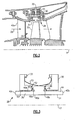
- FIG 2 illustrates a selected portion of the turbine section 20.
- the turbine blade 22 receives a hot gas flow 26 from the combustion section 18 ( Figure 1 ).
- the turbine section 20 includes a blade outer air seal system 28 having an insert member 31 that functions as an outer wall for the hot gas flow 26 through the turbine section 20.
- the insert member 31 is removably secured to a support 30 that includes L-shaped hooks 33 extending therefrom to secure the support 30 to a case 32 that generally surrounds the turbine section 20.
- a plurality of insert members 31 are circumferentially located about the turbine section 20.
- the insert member 31 includes a body 38 that extends between a radially inner side 40a and a radially outer side 40b.
- the body 38 also includes a leading edge 42a, a trailing edge 42b and two circumferential sides 44 (one shown).
- the body 38 includes an attachment section 46 that extends radially outwards from the radially outer side 40b.
- the attachment section 46 includes engagement surfaces 48a and 48b for securing the blade outer air seal 28 to the support 30.
- Each of the engagement surfaces 48a and 48b forms an acute angle 49 with the radially outer side 40b of the body 38. In one example, the acute angle 49 is less than 90°.
- the attachment section 46 is in the shape of a dovetail.
- the dovetail attachment feature has a lesser surface area and therefore reduces loads, inherent from the pressure differential between surfaces 40a and 40b.
- the attachment section 46 is circumferentially slidably receivable into a corresponding section 52 of the support 30 to secure the insert member 31 and the support 30 together.
- the insert member 31 can thereby be removed and replaced simply by sliding it out of engagement with the support 30.
- a bias member 50 located between the insert member 31 and the support 30 biases the insert member 31 in a radially inward direction such that the engagement surfaces 48a and 48b engage the section 52 of the support 30.
- the bias member 50 provides the benefit of sealing the engagement surfaces 48a and 48b against the section 52 of the support 30 when the pressure differential from the hot gas flow 26 is not enough to seal the insert member 31 against the support 30, such as during initial startup of the gas turbine engine 10.
- seal members 53 are located between the support 30 and the insert member 31 to minimize leakage of cooling air and prevent hot gas ingestion into the region between the support 30 and the insert member 31.
- the seals 53 are feather seals that include a strip of sheet metal.
- Figure 4 illustrates selected portions of another example embodiment of the blade outer air seal system 28' wherein the insert member 31' includes a body 38' and an attachment section 46' that slidably secures to support 30'.
- the insert member 31' includes a body 38' and an attachment section 46' that slidably secures to support 30'.
- spacers 60 located between the insert member 31' and the support 30' space the insert member 31' apart from the support 30' such that there is a passage 62 therebetween.
- the spacers 60 are integral with the insert member 31'.
- a coolant is conveyed through the cooling passages 64 within the support 30' and through the passage 62 to cool the insert member 31'.
- FIG. 5 illustrates another embodiment of the blade outer air seal system 28" in which multiple insert members 31" are attached to a single support 30".
- each of the insert members 31" includes a body 38" having an attachment section 46" that is slidably secured into a corresponding section 52" of the support 30", similar to as described for the example shown in Figure 3 .
- the insert members 31" overlap along direction 70. The overlapping of the insert members 31" provides the benefit of protecting the underlying support 30" from the heat of the hot gas flow 26.
- the blade insert member 31, 31', 31" is made of a different material than the support 30, 30', 30".
- the insert member 31, 31', 31" is made of a ceramic material and the support 30, 30', 30" is made of a metal or metal alloy.
- the insert member 31, 31', 31" is made of silicon carbide.
- the silicon carbide includes metallic regions dispersed there through.
- the ceramic material provides the benefit of relatively high temperature resistance compared to the metal or metal alloy and, in some examples, eliminates or reduces the need for cooling using cooling air.
- the disclosed example blade outer air seal inserts 28, 28', 28" permit simplified designs without a need for complex cooling passages.
- the ceramic material provides a relatively high degree of wear resistance, such as for contact with the turbine blades 22 during an initial engine run-in.
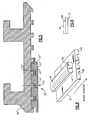
- the support 30 optionally includes a stop section 80 near circumferential side 82 of the support 30.
- the stop section 80 abuts a circumferential side 84 of the attachment section 46 of the insert member 31, which is in the perspective view of Figure 8 and the lateral view of Figure 9 .
- the stop section 80 provides the benefit of restricting circumferential movement of the blade outer air seal insert 28 in at least one circumferential direction.
- the supports 30' and 30" may also optionally include similar stops.
- any of the insert members 31, 31', 31" may also include circumferential grooves 86 to reduce interaction area with the turbine blades 22.
Landscapes
- Engineering & Computer Science (AREA)
- Mechanical Engineering (AREA)
- General Engineering & Computer Science (AREA)
- Turbine Rotor Nozzle Sealing (AREA)
Abstract
Description
- This invention relates to a blade outer air seal ("BOAS") system and, more particularly, to a blade outer air seal system having one or more replaceable members serving as the gas path surface. This scheme allows easy replacement of that portion of the BOAS that is routinely damaged from service usage.
- Conventional gas turbine engines are widely known and used to propel aircraft and other vehicles. Typically, gas turbine engines include a compressor section, a combustor section, and a turbine section that cooperate to provide thrust in a known manner.
- Typically, a blade outer air seal is located radially outwards from the turbine section and functions as an outer wall for the hot gas flow through the gas turbine engine. Due to large pressures and contact with hot gas flow through the turbine section, the blade outer air seal is typically made of a strong, oxidation-resistant metal alloy and requires a cooling system to keep the alloy below a certain temperature. For example, relatively cool air is taken from an air flow through the engine and routed through an intricate system of cooling passages in the seal to maintain a desirable seal temperature. Although effective, taking air from the engine air flow contributes to engine inefficiency by reducing engine thrust, and forming the seal with the cooling passages adds to the expense of the seal.
- Accordingly, there is a need for a simplified and less expensive blade outer air seal that also reduces the need for cooling. This disclosed examples address these needs and provide enhanced capabilities while avoiding the shortcomings and drawbacks of the prior art.
- An example blade outer air seal system includes a body that extends between two circumferential sides, a leading edge and a trailing edge, and a radially inner side and a radially outer side. An attachment section associated with the body and includes at least one engagement surface that is transverse to the radially outer side. For example, the attachment section has a dovetail shape.
- The various features and advantages of this invention will become apparent to those skilled in the art from the following detailed description of the currently preferred embodiment. The drawings that accompany the detailed description can be briefly described as follows.
-
Figure 1 is a schematic view of an example gas turbine engine. -
Figure 2 is a selected portion of a turbine section of the gas turbine engine ofFigure 1 . -
Figure 3 is a circumferential view of an example blade outer air seal system. -
Figure 4 is another example of a blade outer air seal system. -
Figure 5 is another example having a plurality of blade outer air seal members secured to a single support. -
Figure 6 is an axial cross-sectional view of an example blade outer air seal system secured to a support, wherein the support includes a stop to prevent circumferential movement of a blade outer air seal member. -
Figure 7 is a circumferential cross-sectional view of the support shown inFigure 6 . -
Figure 8 is a perspective view of a blade outer air seal member that abuts the stop of the support shown inFigure 6 . -
Figure 9 is a lateral view of the blade outer air seal member shown inFigure 8 . -
Figure 1 illustrates selected portions of an examplegas turbine engine 10, such as agas turbine engine 10 used for propulsion. In this example, thegas turbine engine 10 is circumferentially disposed about anengine centerline 12. Theengine 10 includes afan 14, acompressor section 16, acombustion section 18 and aturbine section 20 that includesturbine blades 22 andturbine vanes 24. As is known, air compressed in thecompressor section 16 is mixed with fuel that is burned in thecombustion section 18 to produce hot gases that are expanded in theturbine section 20.Figure 1 is a somewhat schematic presentation for illustrative purposes only and is not a limitation on the disclosed examples. Additionally, there are various types of gas turbine engines, many of which could benefit from the examples disclosed herein, which are not limited to the design shown. -
Figure 2 illustrates a selected portion of theturbine section 20. Theturbine blade 22 receives ahot gas flow 26 from the combustion section 18 (Figure 1 ). Theturbine section 20 includes a blade outerair seal system 28 having aninsert member 31 that functions as an outer wall for thehot gas flow 26 through theturbine section 20. In the disclosed example, theinsert member 31 is removably secured to asupport 30 that includes L-shaped hooks 33 extending therefrom to secure thesupport 30 to acase 32 that generally surrounds theturbine section 20. In one example, a plurality ofinsert members 31 are circumferentially located about theturbine section 20. - Referring to
Figure 3 , theinsert member 31 includes abody 38 that extends between a radiallyinner side 40a and a radially outer side 40b. Thebody 38 also includes a leadingedge 42a, atrailing edge 42b and two circumferential sides 44 (one shown). - In this example, the
body 38 includes anattachment section 46 that extends radially outwards from the radially outer side 40b. Theattachment section 46 includesengagement surfaces outer air seal 28 to thesupport 30. Each of theengagement surfaces acute angle 49 with the radially outer side 40b of thebody 38. In one example, theacute angle 49 is less than 90°. - In the illustrated example, the
attachment section 46 is in the shape of a dovetail. The dovetail attachment feature has a lesser surface area and therefore reduces loads, inherent from the pressure differential betweensurfaces 40a and 40b. - The
attachment section 46 is circumferentially slidably receivable into acorresponding section 52 of thesupport 30 to secure theinsert member 31 and thesupport 30 together. Theinsert member 31 can thereby be removed and replaced simply by sliding it out of engagement with thesupport 30. - Optionally, a
bias member 50 located between theinsert member 31 and thesupport 30 biases theinsert member 31 in a radially inward direction such that theengagement surfaces section 52 of thesupport 30. Thebias member 50 provides the benefit of sealing theengagement surfaces section 52 of thesupport 30 when the pressure differential from thehot gas flow 26 is not enough to seal theinsert member 31 against thesupport 30, such as during initial startup of thegas turbine engine 10. - Optionally,
seal members 53 are located between thesupport 30 and theinsert member 31 to minimize leakage of cooling air and prevent hot gas ingestion into the region between thesupport 30 and theinsert member 31. In one example, theseals 53 are feather seals that include a strip of sheet metal. -
Figure 4 illustrates selected portions of another example embodiment of the blade outer air seal system 28' wherein the insert member 31' includes a body 38' and an attachment section 46' that slidably secures to support 30'. In this example,spacers 60 located between the insert member 31' and the support 30' space the insert member 31' apart from the support 30' such that there is apassage 62 therebetween. In one example, thespacers 60 are integral with the insert member 31'. In the illustrated example, a coolant is conveyed through thecooling passages 64 within the support 30' and through thepassage 62 to cool the insert member 31'. -
Figure 5 illustrates another embodiment of the blade outerair seal system 28" in whichmultiple insert members 31" are attached to asingle support 30". In this example, each of theinsert members 31" includes abody 38" having anattachment section 46" that is slidably secured into acorresponding section 52" of thesupport 30", similar to as described for the example shown inFigure 3 . In this example, theinsert members 31" overlap along direction 70. The overlapping of theinsert members 31" provides the benefit of protecting theunderlying support 30" from the heat of thehot gas flow 26. - In one example, the blade insert
member support insert member support insert member - The ceramic material provides the benefit of relatively high temperature resistance compared to the metal or metal alloy and, in some examples, eliminates or reduces the need for cooling using cooling air. Thus, the disclosed example blade outer air seal inserts 28, 28', 28" permit simplified designs without a need for complex cooling passages. Additionally, the ceramic material provides a relatively high degree of wear resistance, such as for contact with the
turbine blades 22 during an initial engine run-in. - Referring to
Figures 6 and 7 , thesupport 30 optionally includes astop section 80 nearcircumferential side 82 of thesupport 30. In this example, thestop section 80 abuts acircumferential side 84 of theattachment section 46 of theinsert member 31, which is in the perspective view ofFigure 8 and the lateral view ofFigure 9 . Thestop section 80 provides the benefit of restricting circumferential movement of the blade outerair seal insert 28 in at least one circumferential direction. Likewise, thesupports 30' and 30" may also optionally include similar stops. Additionally, any of theinsert members circumferential grooves 86 to reduce interaction area with theturbine blades 22. - Although a combination of features is shown in the illustrated examples, not all of them need to be combined to realize the benefits of various embodiments of this disclosure. In other words, a system designed according to an embodiment of this disclosure will not necessarily include all of the features shown in any one of the Figures or all of the portions schematically shown in the Figures. Moreover, selected features of one example embodiment may be combined with selected features of other example embodiments.
- Although a preferred embodiment of this invention has been disclosed, a worker of ordinary skill in this art would recognize that certain modifications would come within the scope of this invention. For that reason, the following claims should be studied to determine the true scope and content of this invention.
Claims (19)
Applications Claiming Priority (1)
| Application Number | Priority Date | Filing Date | Title |
|---|---|---|---|
| US11/648,932 US9039358B2 (en) | 2007-01-03 | 2007-01-03 | Replaceable blade outer air seal design |
Publications (3)
| Publication Number | Publication Date |
|---|---|
| EP1944474A2 true EP1944474A2 (en) | 2008-07-16 |
| EP1944474A3 EP1944474A3 (en) | 2009-03-25 |
| EP1944474B1 EP1944474B1 (en) | 2011-02-16 |
Family
ID=39154146
Family Applications (1)
| Application Number | Title | Priority Date | Filing Date |
|---|---|---|---|
| EP07254878A Active EP1944474B1 (en) | 2007-01-03 | 2007-12-14 | Gas turbine shroud seal and corresponding gas turbine engine |
Country Status (3)
| Country | Link |
|---|---|
| US (1) | US9039358B2 (en) |
| EP (1) | EP1944474B1 (en) |
| DE (1) | DE602007012516D1 (en) |
Cited By (6)
| Publication number | Priority date | Publication date | Assignee | Title |
|---|---|---|---|---|
| WO2014163674A1 (en) * | 2013-03-13 | 2014-10-09 | Freeman Ted J | Dovetail retention system for blade tracks |
| US9416671B2 (en) | 2012-10-04 | 2016-08-16 | General Electric Company | Bimetallic turbine shroud and method of fabricating |
| WO2017058745A1 (en) * | 2015-09-30 | 2017-04-06 | Siemens Aktiengesellschaft | Gas turbine compressor with adaptive blade tip seal assembly |
| WO2017058740A1 (en) * | 2015-09-30 | 2017-04-06 | Siemens Aktiengesellschaft | Gas turbine compressor with adaptive blade tip seal assembly |
| US9759082B2 (en) | 2013-03-12 | 2017-09-12 | Rolls-Royce Corporation | Turbine blade track assembly |
| US9988923B2 (en) | 2013-08-29 | 2018-06-05 | United Technologies Corporation | Seal for gas turbine engine |
Families Citing this family (71)
| Publication number | Priority date | Publication date | Assignee | Title |
|---|---|---|---|---|
| US8529201B2 (en) * | 2009-12-17 | 2013-09-10 | United Technologies Corporation | Blade outer air seal formed of stacked panels |
| US8534673B2 (en) * | 2010-08-20 | 2013-09-17 | Mitsubishi Power Systems Americas, Inc. | Inter stage seal housing having a replaceable wear strip |
| EP2495399B1 (en) | 2011-03-03 | 2016-11-23 | Safran Aero Booster S.A. | Segmented shroud assembly suitable for compensating a rotor misalignment relative to the stator |
| US9169739B2 (en) * | 2012-01-04 | 2015-10-27 | United Technologies Corporation | Hybrid blade outer air seal for gas turbine engine |
| US9404580B2 (en) * | 2012-04-13 | 2016-08-02 | United Technologies Corporation | Duplex finger seal for joints with high relative displacement |
| US8998572B2 (en) | 2012-06-04 | 2015-04-07 | United Technologies Corporation | Blade outer air seal for a gas turbine engine |
| US9255524B2 (en) | 2012-12-20 | 2016-02-09 | United Technologies Corporation | Variable outer air seal fluid control |
| US9371738B2 (en) | 2012-12-20 | 2016-06-21 | United Technologies Corporation | Variable outer air seal support |
| WO2014204574A2 (en) * | 2013-06-21 | 2014-12-24 | United Technologies Corporation | Seals for gas turbine engine |
| EP2835500A1 (en) | 2013-08-09 | 2015-02-11 | Siemens Aktiengesellschaft | Insert element and gas turbine |
| WO2015038341A1 (en) * | 2013-09-11 | 2015-03-19 | United Technologies Corporation | Blade outer air seal having angled retention hook |
| JP6161208B2 (en) * | 2014-10-30 | 2017-07-12 | 三菱日立パワーシステムズ株式会社 | Clearance control type seal structure |
| US10100649B2 (en) * | 2015-03-31 | 2018-10-16 | Rolls-Royce North American Technologies Inc. | Compliant rail hanger |
| US20170030212A1 (en) * | 2015-07-29 | 2017-02-02 | General Electric Company | Near flow path seal for a turbomachine |
| US10138749B2 (en) | 2016-03-16 | 2018-11-27 | United Technologies Corporation | Seal anti-rotation feature |
| US10415414B2 (en) | 2016-03-16 | 2019-09-17 | United Technologies Corporation | Seal arc segment with anti-rotation feature |
| US10132184B2 (en) | 2016-03-16 | 2018-11-20 | United Technologies Corporation | Boas spring loaded rail shield |
| US10337346B2 (en) | 2016-03-16 | 2019-07-02 | United Technologies Corporation | Blade outer air seal with flow guide manifold |
| US10422240B2 (en) | 2016-03-16 | 2019-09-24 | United Technologies Corporation | Turbine engine blade outer air seal with load-transmitting cover plate |
| US10563531B2 (en) | 2016-03-16 | 2020-02-18 | United Technologies Corporation | Seal assembly for gas turbine engine |
| US10422241B2 (en) | 2016-03-16 | 2019-09-24 | United Technologies Corporation | Blade outer air seal support for a gas turbine engine |
| US10107129B2 (en) | 2016-03-16 | 2018-10-23 | United Technologies Corporation | Blade outer air seal with spring centering |
| US10138750B2 (en) | 2016-03-16 | 2018-11-27 | United Technologies Corporation | Boas segmented heat shield |
| US10513943B2 (en) | 2016-03-16 | 2019-12-24 | United Technologies Corporation | Boas enhanced heat transfer surface |
| US10443616B2 (en) | 2016-03-16 | 2019-10-15 | United Technologies Corporation | Blade outer air seal with centrally mounted seal arc segments |
| US10161258B2 (en) | 2016-03-16 | 2018-12-25 | United Technologies Corporation | Boas rail shield |
| US10443424B2 (en) | 2016-03-16 | 2019-10-15 | United Technologies Corporation | Turbine engine blade outer air seal with load-transmitting carriage |
| US10280799B2 (en) | 2016-06-10 | 2019-05-07 | United Technologies Corporation | Blade outer air seal assembly with positioning feature for gas turbine engine |
| US10697314B2 (en) | 2016-10-14 | 2020-06-30 | Rolls-Royce Corporation | Turbine shroud with I-beam construction |
| US10711624B2 (en) | 2016-11-17 | 2020-07-14 | Raytheon Technologies Corporation | Airfoil with geometrically segmented coating section |
| US10598025B2 (en) | 2016-11-17 | 2020-03-24 | United Technologies Corporation | Airfoil with rods adjacent a core structure |
| US10662782B2 (en) | 2016-11-17 | 2020-05-26 | Raytheon Technologies Corporation | Airfoil with airfoil piece having axial seal |
| US10570765B2 (en) | 2016-11-17 | 2020-02-25 | United Technologies Corporation | Endwall arc segments with cover across joint |
| US10746038B2 (en) | 2016-11-17 | 2020-08-18 | Raytheon Technologies Corporation | Airfoil with airfoil piece having radial seal |
| US10808554B2 (en) | 2016-11-17 | 2020-10-20 | Raytheon Technologies Corporation | Method for making ceramic turbine engine article |
| US10677091B2 (en) | 2016-11-17 | 2020-06-09 | Raytheon Technologies Corporation | Airfoil with sealed baffle |
| US10502070B2 (en) | 2016-11-17 | 2019-12-10 | United Technologies Corporation | Airfoil with laterally insertable baffle |
| US10408090B2 (en) | 2016-11-17 | 2019-09-10 | United Technologies Corporation | Gas turbine engine article with panel retained by preloaded compliant member |
| US10480334B2 (en) | 2016-11-17 | 2019-11-19 | United Technologies Corporation | Airfoil with geometrically segmented coating section |
| US10711616B2 (en) | 2016-11-17 | 2020-07-14 | Raytheon Technologies Corporation | Airfoil having endwall panels |
| US10711794B2 (en) | 2016-11-17 | 2020-07-14 | Raytheon Technologies Corporation | Airfoil with geometrically segmented coating section having mechanical secondary bonding feature |
| US10598029B2 (en) | 2016-11-17 | 2020-03-24 | United Technologies Corporation | Airfoil with panel and side edge cooling |
| US10408082B2 (en) | 2016-11-17 | 2019-09-10 | United Technologies Corporation | Airfoil with retention pocket holding airfoil piece |
| US10767487B2 (en) * | 2016-11-17 | 2020-09-08 | Raytheon Technologies Corporation | Airfoil with panel having flow guide |
| US10662779B2 (en) | 2016-11-17 | 2020-05-26 | Raytheon Technologies Corporation | Gas turbine engine component with degradation cooling scheme |
| US10428658B2 (en) | 2016-11-17 | 2019-10-01 | United Technologies Corporation | Airfoil with panel fastened to core structure |
| US10436062B2 (en) | 2016-11-17 | 2019-10-08 | United Technologies Corporation | Article having ceramic wall with flow turbulators |
| US10605088B2 (en) | 2016-11-17 | 2020-03-31 | United Technologies Corporation | Airfoil endwall with partial integral airfoil wall |
| US10458262B2 (en) | 2016-11-17 | 2019-10-29 | United Technologies Corporation | Airfoil with seal between endwall and airfoil section |
| US10415407B2 (en) | 2016-11-17 | 2019-09-17 | United Technologies Corporation | Airfoil pieces secured with endwall section |
| US10309226B2 (en) | 2016-11-17 | 2019-06-04 | United Technologies Corporation | Airfoil having panels |
| US10677079B2 (en) | 2016-11-17 | 2020-06-09 | Raytheon Technologies Corporation | Airfoil with ceramic airfoil piece having internal cooling circuit |
| US10309238B2 (en) | 2016-11-17 | 2019-06-04 | United Technologies Corporation | Turbine engine component with geometrically segmented coating section and cooling passage |
| US10480331B2 (en) | 2016-11-17 | 2019-11-19 | United Technologies Corporation | Airfoil having panel with geometrically segmented coating |
| US10436049B2 (en) | 2016-11-17 | 2019-10-08 | United Technologies Corporation | Airfoil with dual profile leading end |
| US10731495B2 (en) | 2016-11-17 | 2020-08-04 | Raytheon Technologies Corporation | Airfoil with panel having perimeter seal |
| US10428663B2 (en) | 2016-11-17 | 2019-10-01 | United Technologies Corporation | Airfoil with tie member and spring |
| US10704407B2 (en) | 2017-04-21 | 2020-07-07 | Rolls-Royce High Temperature Composites Inc. | Ceramic matrix composite blade track segments |
| US10364707B2 (en) | 2017-06-16 | 2019-07-30 | General Electric Company | Retention assembly for gas turbine engine components |
| US10557365B2 (en) | 2017-10-05 | 2020-02-11 | Rolls-Royce Corporation | Ceramic matrix composite blade track with mounting system having reaction load distribution features |
| US20190284947A1 (en) * | 2018-03-14 | 2019-09-19 | General Electric Company | Cmc shroud segment with interlocking mechanical joints and fabrication |
| US10738628B2 (en) * | 2018-05-25 | 2020-08-11 | General Electric Company | Joint for band features on turbine nozzle and fabrication |
| US11035243B2 (en) | 2018-06-01 | 2021-06-15 | Raytheon Technologies Corporation | Seal assembly for gas turbine engines |
| US11125096B2 (en) * | 2019-05-03 | 2021-09-21 | Raytheon Technologies Corporation | CMC boas arrangement |
| US11220924B2 (en) | 2019-09-26 | 2022-01-11 | Raytheon Technologies Corporation | Double box composite seal assembly with insert for gas turbine engine |
| US11359507B2 (en) | 2019-09-26 | 2022-06-14 | Raytheon Technologies Corporation | Double box composite seal assembly with fiber density arrangement for gas turbine engine |
| US11352897B2 (en) | 2019-09-26 | 2022-06-07 | Raytheon Technologies Corporation | Double box composite seal assembly for gas turbine engine |
| US11149563B2 (en) | 2019-10-04 | 2021-10-19 | Rolls-Royce Corporation | Ceramic matrix composite blade track with mounting system having axial reaction load distribution features |
| US11125099B2 (en) * | 2019-11-06 | 2021-09-21 | Raytheon Technologies Corporation | Boas arrangement with double dovetail attachments |
| US11111796B1 (en) | 2020-05-18 | 2021-09-07 | Rolls-Royce North American Technologies Inc. | Turbine shroud assembly with dovetail retention system |
| US11230937B2 (en) | 2020-05-18 | 2022-01-25 | Rolls-Royce North American Technologies Inc. | Turbine shroud assembly with dovetail retention system |
Citations (1)
| Publication number | Priority date | Publication date | Assignee | Title |
|---|---|---|---|---|
| US4087199A (en) | 1976-11-22 | 1978-05-02 | General Electric Company | Ceramic turbine shroud assembly |
Family Cites Families (18)
| Publication number | Priority date | Publication date | Assignee | Title |
|---|---|---|---|---|
| US899319A (en) * | 1906-10-08 | 1908-09-22 | Charles Algernon Parsons | Turbine. |
| US994029A (en) * | 1907-08-12 | 1911-05-30 | Charles Algernon Parsons | Strips for turbine-blades. |
| DE1057827B (en) | 1955-08-18 | 1959-05-21 | Stroemungsmasch Anst | Fixed impeller rim for gas turbines |
| GB2397102B (en) | 1981-12-30 | 2004-11-03 | Rolls Royce | Turbine shroud assembly |
| FR2540560B1 (en) | 1983-02-03 | 1987-06-12 | Snecma | DEVICE FOR SEALING MOBILE BLADES OF A TURBOMACHINE |
| US4728257A (en) | 1986-06-18 | 1988-03-01 | The United States Of America As Represented By The Administrator Of The National Aeronautics And Space Administration | Thermal stress minimized, two component, turbine shroud seal |
| FR2604750B1 (en) | 1986-10-01 | 1988-12-02 | Snecma | TURBOMACHINE PROVIDED WITH AN AUTOMATIC CONTROL DEVICE FOR TURBINE VENTILATION FLOWS |
| US5080556A (en) * | 1990-09-28 | 1992-01-14 | General Electric Company | Thermal seal for a gas turbine spacer disc |
| FR2711730B1 (en) | 1993-10-27 | 1995-12-01 | Snecma | Turbomachine equipped with means for controlling the clearances between rotor and stator. |
| US5456576A (en) * | 1994-08-31 | 1995-10-10 | United Technologies Corporation | Dynamic control of tip clearance |
| US5934684A (en) * | 1997-05-27 | 1999-08-10 | Brandon; Ronald Earl | Retractable segmented packing ring for fluid turbines having gravity springs to neutralize packing segment weight forces |
| US6142731A (en) * | 1997-07-21 | 2000-11-07 | Caterpillar Inc. | Low thermal expansion seal ring support |
| DE19938274A1 (en) | 1999-08-12 | 2001-02-15 | Asea Brown Boveri | Device and method for drawing the gap between the stator and rotor arrangement of a turbomachine |
| EP1118806A1 (en) | 2000-01-20 | 2001-07-25 | Siemens Aktiengesellschaft | Thermally charged wall structure and method to seal gaps in such a structure |
| US6514041B1 (en) | 2001-09-12 | 2003-02-04 | Alstom (Switzerland) Ltd | Carrier for guide vane and heat shield segment |
| US6733235B2 (en) | 2002-03-28 | 2004-05-11 | General Electric Company | Shroud segment and assembly for a turbine engine |
| US6877952B2 (en) | 2002-09-09 | 2005-04-12 | Florida Turbine Technologies, Inc | Passive clearance control |
| US7052235B2 (en) * | 2004-06-08 | 2006-05-30 | General Electric Company | Turbine engine shroud segment, hanger and assembly |
-
2007
- 2007-01-03 US US11/648,932 patent/US9039358B2/en active Active
- 2007-12-14 DE DE602007012516T patent/DE602007012516D1/en active Active
- 2007-12-14 EP EP07254878A patent/EP1944474B1/en active Active
Patent Citations (1)
| Publication number | Priority date | Publication date | Assignee | Title |
|---|---|---|---|---|
| US4087199A (en) | 1976-11-22 | 1978-05-02 | General Electric Company | Ceramic turbine shroud assembly |
Cited By (10)
| Publication number | Priority date | Publication date | Assignee | Title |
|---|---|---|---|---|
| US9416671B2 (en) | 2012-10-04 | 2016-08-16 | General Electric Company | Bimetallic turbine shroud and method of fabricating |
| US9759082B2 (en) | 2013-03-12 | 2017-09-12 | Rolls-Royce Corporation | Turbine blade track assembly |
| US10364693B2 (en) | 2013-03-12 | 2019-07-30 | Rolls-Royce Corporation | Turbine blade track assembly |
| WO2014163674A1 (en) * | 2013-03-13 | 2014-10-09 | Freeman Ted J | Dovetail retention system for blade tracks |
| US9458726B2 (en) | 2013-03-13 | 2016-10-04 | Rolls-Royce Corporation | Dovetail retention system for blade tracks |
| US9988923B2 (en) | 2013-08-29 | 2018-06-05 | United Technologies Corporation | Seal for gas turbine engine |
| WO2017058745A1 (en) * | 2015-09-30 | 2017-04-06 | Siemens Aktiengesellschaft | Gas turbine compressor with adaptive blade tip seal assembly |
| WO2017058740A1 (en) * | 2015-09-30 | 2017-04-06 | Siemens Aktiengesellschaft | Gas turbine compressor with adaptive blade tip seal assembly |
| US10077782B2 (en) | 2015-09-30 | 2018-09-18 | Siemens Aktiengesellschaft | Adaptive blade tip seal assembly |
| US10082152B2 (en) | 2015-09-30 | 2018-09-25 | Siemens Aktiengsellschaft | Gas turbine compressor with adaptive blade tip seal assembly |
Also Published As
| Publication number | Publication date |
|---|---|
| DE602007012516D1 (en) | 2011-03-31 |
| EP1944474A3 (en) | 2009-03-25 |
| US9039358B2 (en) | 2015-05-26 |
| US20080159850A1 (en) | 2008-07-03 |
| EP1944474B1 (en) | 2011-02-16 |
Similar Documents
| Publication | Publication Date | Title |
|---|---|---|
| EP1944474B1 (en) | Gas turbine shroud seal and corresponding gas turbine engine | |
| US7217089B2 (en) | Gas turbine engine shroud sealing arrangement | |
| EP2834498B1 (en) | Cooling system for a turbine vane | |
| US8166767B2 (en) | Gas turbine combustor exit duct and hp vane interface | |
| US8684680B2 (en) | Sealing and cooling at the joint between shroud segments | |
| CA2513079C (en) | Lightweight annular interturbine duct | |
| EP3155231B1 (en) | Shroud hanger assembly | |
| US9816393B2 (en) | Turbine blade and turbine with improved sealing | |
| EP2570612B1 (en) | Turbomachine secondary seal assembly | |
| EP0916811A2 (en) | Ribbed turbine blade tip | |
| US20090010758A1 (en) | Suspension arrangement for the casing shroud segments | |
| US10597334B2 (en) | Turbine comprising turbine stator vanes of a ceramic matrix composite attached to a turbine case | |
| US9133726B2 (en) | Seal for gas turbine engine component | |
| US11193392B2 (en) | CMC ply overlap ingestion restrictor | |
| US20130315708A1 (en) | Nozzle with Extended Tab | |
| US11566536B1 (en) | Turbine HGP component with stress relieving cooling circuit | |
| US20060182633A1 (en) | Turbine blade | |
| JP2018524513A (en) | Turbine blade with shroud | |
| US20190136700A1 (en) | Ceramic matrix composite tip shroud assembly for gas turbines | |
| EP2157281B1 (en) | A gas turbine blade with impingement cooling | |
| EP3047130B1 (en) | A gas turbine seal assembly comprising splined honeycomb seals | |
| GB2434842A (en) | Cooling arrangement for a turbine blade shroud | |
| US7534085B2 (en) | Gas turbine engine with contoured air supply slot in turbine rotor | |
| EP1944473A2 (en) | Nozzle guide vane arrangement | |
| EP3015657A1 (en) | Gas turbine nozzle vane segment |
Legal Events
| Date | Code | Title | Description |
|---|---|---|---|
| PUAI | Public reference made under article 153(3) epc to a published international application that has entered the european phase |
Free format text: ORIGINAL CODE: 0009012 |
|
| AK | Designated contracting states |
Kind code of ref document: A2 Designated state(s): AT BE BG CH CY CZ DE DK EE ES FI FR GB GR HU IE IS IT LI LT LU LV MC MT NL PL PT RO SE SI SK TR |
|
| AX | Request for extension of the european patent |
Extension state: AL BA HR MK RS |
|
| PUAL | Search report despatched |
Free format text: ORIGINAL CODE: 0009013 |
|
| AK | Designated contracting states |
Kind code of ref document: A3 Designated state(s): AT BE BG CH CY CZ DE DK EE ES FI FR GB GR HU IE IS IT LI LT LU LV MC MT NL PL PT RO SE SI SK TR |
|
| AX | Request for extension of the european patent |
Extension state: AL BA HR MK RS |
|
| RIC1 | Information provided on ipc code assigned before grant |
Ipc: F01D 11/18 20060101ALI20090218BHEP Ipc: F01D 9/04 20060101ALI20090218BHEP Ipc: F01D 11/16 20060101AFI20080314BHEP Ipc: F01D 11/08 20060101ALI20090218BHEP Ipc: F01D 11/12 20060101ALI20090218BHEP |
|
| 17P | Request for examination filed |
Effective date: 20090605 |
|
| 17Q | First examination report despatched |
Effective date: 20090720 |
|
| AKX | Designation fees paid |
Designated state(s): DE GB |
|
| GRAJ | Information related to disapproval of communication of intention to grant by the applicant or resumption of examination proceedings by the epo deleted |
Free format text: ORIGINAL CODE: EPIDOSDIGR1 |
|
| GRAP | Despatch of communication of intention to grant a patent |
Free format text: ORIGINAL CODE: EPIDOSNIGR1 |
|
| GRAS | Grant fee paid |
Free format text: ORIGINAL CODE: EPIDOSNIGR3 |
|
| GRAA | (expected) grant |
Free format text: ORIGINAL CODE: 0009210 |
|
| AK | Designated contracting states |
Kind code of ref document: B1 Designated state(s): DE GB |
|
| REG | Reference to a national code |
Ref country code: GB Ref legal event code: FG4D |
|
| REF | Corresponds to: |
Ref document number: 602007012516 Country of ref document: DE Date of ref document: 20110331 Kind code of ref document: P |
|
| REG | Reference to a national code |
Ref country code: DE Ref legal event code: R096 Ref document number: 602007012516 Country of ref document: DE Effective date: 20110331 |
|
| PLBE | No opposition filed within time limit |
Free format text: ORIGINAL CODE: 0009261 |
|
| STAA | Information on the status of an ep patent application or granted ep patent |
Free format text: STATUS: NO OPPOSITION FILED WITHIN TIME LIMIT |
|
| 26N | No opposition filed |
Effective date: 20111117 |
|
| REG | Reference to a national code |
Ref country code: DE Ref legal event code: R097 Ref document number: 602007012516 Country of ref document: DE Effective date: 20111117 |
|
| REG | Reference to a national code |
Ref country code: DE Ref legal event code: R082 Ref document number: 602007012516 Country of ref document: DE Representative=s name: SCHMITT-NILSON SCHRAUD WAIBEL WOHLFROM PATENTA, DE |
|
| REG | Reference to a national code |
Ref country code: DE Ref legal event code: R082 Ref document number: 602007012516 Country of ref document: DE Representative=s name: SCHMITT-NILSON SCHRAUD WAIBEL WOHLFROM PATENTA, DE Ref country code: DE Ref legal event code: R081 Ref document number: 602007012516 Country of ref document: DE Owner name: UNITED TECHNOLOGIES CORP. (N.D.GES.D. STAATES , US Free format text: FORMER OWNER: UNITED TECHNOLOGIES CORP., HARTFORD, CONN., US |
|
| PGFP | Annual fee paid to national office [announced via postgrant information from national office to epo] |
Ref country code: DE Payment date: 20201119 Year of fee payment: 14 |
|
| REG | Reference to a national code |
Ref country code: DE Ref legal event code: R119 Ref document number: 602007012516 Country of ref document: DE |
|
| PG25 | Lapsed in a contracting state [announced via postgrant information from national office to epo] |
Ref country code: DE Free format text: LAPSE BECAUSE OF NON-PAYMENT OF DUE FEES Effective date: 20220701 |
|
| PGFP | Annual fee paid to national office [announced via postgrant information from national office to epo] |
Ref country code: GB Payment date: 20251120 Year of fee payment: 19 |
|
| P01 | Opt-out of the competence of the unified patent court (upc) registered |
Free format text: CASE NUMBER: UPC_APP_0018210_1944474/2025 Effective date: 20251218 |