EP1943996A2 - Tiltable operating table - Google Patents
Tiltable operating table Download PDFInfo
- Publication number
- EP1943996A2 EP1943996A2 EP07024343A EP07024343A EP1943996A2 EP 1943996 A2 EP1943996 A2 EP 1943996A2 EP 07024343 A EP07024343 A EP 07024343A EP 07024343 A EP07024343 A EP 07024343A EP 1943996 A2 EP1943996 A2 EP 1943996A2
- Authority
- EP
- European Patent Office
- Prior art keywords
- tabletop
- surgical table
- guide
- head
- slide
- Prior art date
- Legal status (The legal status is an assumption and is not a legal conclusion. Google has not performed a legal analysis and makes no representation as to the accuracy of the status listed.)
- Granted
Links
Images


Classifications
-
- A—HUMAN NECESSITIES
- A61—MEDICAL OR VETERINARY SCIENCE; HYGIENE
- A61G—TRANSPORT, PERSONAL CONVEYANCES, OR ACCOMMODATION SPECIALLY ADAPTED FOR PATIENTS OR DISABLED PERSONS; OPERATING TABLES OR CHAIRS; CHAIRS FOR DENTISTRY; FUNERAL DEVICES
- A61G13/00—Operating tables; Auxiliary appliances therefor
- A61G13/02—Adjustable operating tables; Controls therefor
- A61G13/04—Adjustable operating tables; Controls therefor tiltable around transverse or longitudinal axis
Definitions
- the present invention generally finds application in the art of medical apparatus and particularly relates to a surgical table that is adjustable to adapt the position of a patient lying thereon to the required surgery procedure or diagnostic analysis.
- Surgical tables for use in surgery or diagnostics are known to be essentially composed of a base column standing on the floor, and supporting a tabletop designed to receive a patient in lying, supine, sitting or even complex positions, depending on the specific type of examination.
- the latter is driven for the patient to take the position that is most appropriate with respect to the particular type of surgery or analysis, and most comfortable for the surgeon or operator.
- surgical tables shall be able to translate along one or more axes, i.e. for adjusting the height of the tabletop to the height of the surgeon, and to rotate about one or more axes for positioning the patient body, or a part thereof, possibly in oblique directions.
- WO02/111618 discloses a surgical table comprising a horizontal tabletop mounted to a load-bearing column and adapted to slide in the direction of its length by means of a carriage movable along a pair of straight rails, one of which is associated with the tabletop and the other with the column.
- DE10253878 discloses a surgical table that is removably mounted to a load-bearing column so that it can be rotated relative thereto to the desired position.
- a greater tilt may particularly be needed when the patient has to be moved to the so-called “Trendelenburg position", which is useful during certain radiological imaging procedures, such as for diagnosis of reflux esophagitis or hiatal hernia, in which the patient is laid in a supine position on a tilted tabletop, with the head lower than the knees and pelvis, or to the reverse Trendelenburd position, with the head higher than the knees and pelvis, which is useful for procedures on obese patients.
- Trendelenburg position which is useful during certain radiological imaging procedures, such as for diagnosis of reflux esophagitis or hiatal hernia, in which the patient is laid in a supine position on a tilted tabletop, with the head lower than the knees and pelvis, or to the reverse Trendelenburd position, with the head higher than the knees and pelvis, which is useful for procedures on obese patients.
- Another critical aspect is the possibility of placing the tabletop at a minimum height from the floor to adapt the tabletop height to the height of the surgeon, for improved operating comfort.
- US6070281 discloses an adjustable surgical table connected to a base via a movable C-arm which causes combined translation thereof in space in the longitudinal and vertical directions.
- the table is articulated at one end of the arm for further rotation and, in combination with the motion of the C-arm, this provides large tilts of the tabletop, possibly reaching the totally vertical position.
- US5790996 discloses a similar solution in which the movable C-arm is articulated to the base and the tabletop is slideably mounted thereto.
- the object of the present invention is to overcome the above drawbacks, by providing an adjustable surgical table that is highly efficient and relatively cost-effective.
- a particular object is to provide an adjustable surgical table that allows for large tabletop tilts relative to a median vertical plane, particularly when the patient has to be moved to the Trendelenburg or reverse Trendelenburg position.
- a further object is to provide an adjustable surgical table that allows tabletop translation along its length to eliminate blind spots for X-ray diagnostic apparatus.
- Yet another object is to provide a surgical table that can be placed at a minimum height from the floor for the patient position to be as comfortable as possible for the surgeon or operator, and adapted to different heights.
- a further object is to provide an adjustable surgical table that affords high positioning flexibility as well as sturdy and reliable construction, to allow even arrangement of the loads supported by the surgical table.
- Another important object is to provide a surgical table that can be adjusted in space in a relatively simple manner, while remaining comfortable for the patient, by perfectly synchronous movements of its parts.
- a tiltable surgical table as defined in claim 1, comprising a floor-standing load-bearing column, having a substantially conical upper head which defines a substantially vertical axis of symmetry, a tabletop mounted to said head, guide means for guiding said tabletop along a longitudinal plane of symmetry passing through said vertical axis, wherein said guide means comprise a curved guide associated with said column and at least one slide adapted to move on the guide, first actuator means operating on said at least one slide to cause motion thereof along said at least one curved guide.
- the table is characterized in that the curved guide is adapted to be fixed to the head and the slide is rigidly connected to the tabletop, locked against rotation relative thereto and in that the first actuator means are removably mounted to the head to cause motion of the slide relative to the guide.
- This particular configuration of the invention allows for extreme tabletop positioning, with considerably greater tilts to the vertical as compared with usual values obtained using standard surgical tables guided along straight guides.
- the curved guide may include a pair of supports having a substantially cylindrical upwardly concave top surface, which are disposed symmetrically about the longitudinal plane of symmetry.
- the slide may include a pair of arched elements whose bottom surface is complementary in shape to the top surface of the supports.
- the surgical table of the invention may be used to adapt the position of a patient to a given surgical procedure or diagnostic examination.
- the table 1 may be used in combination with suitable diagnostic apparatus, e.g. for X-ray imaging, not shown because they are known per se.
- the surgical table as shown in FIG. 1 , comprises a floor-standing load-bearing column 2 having a substantially conical upper head 3 that defines a substantially vertical axis of symmetry W, a tabletop 4 mounted to the head 3, guide means 5 for guiding the tabletop 4 along a longitudinal plane of symmetry ⁇ passing through the vertical axis W.
- the guide means 5 include a curved guide 6 associated with the column 2 when the tabletop 4 is mounted thereon, and a slide 7 movable on the guide 6.
- First actuator means 8 are provided, which operate on the slide 7 to cause motion thereof along the curved guide 6.
- the curved guide 6 is designed for attachment to the head 3 and the slide 7 is rigidly connected to the tabletop 4 and locked against rotation relative thereto.
- the first actuator means 8 are in turn removably mounted to the head 3 to cause the slide 7 to move relative to the guide 6.
- the guide 6 may be fixedly ore movably attached to the head 3 of the column 2.
- the guide may include a pair of lateral supports 9, 9' each having a substantially cylindrical upwardly concave top surface 10, which are disposed symmetrically about the longitudinal plane of symmetry ⁇ .
- the slide 7 may include a pair of arched elements 11, 11', each having a bottom surface 12, 12' complementary in shape to the top surface 10 of the corresponding support 9, 9', for causing rotation of the tabletop 4 at the same time as the arched elements 11, 11' slide within the lateral supports 9, 9' of the guide 6.
- the first actuator means 8 may include one or more kinematic pairs 13 located at the ends of a first motorized drive shaft 14, having a first transverse axis X, which is rotatably mounted to the guide 6.
- the shaft 14 may be rotated by a motor 16, which is coupled to the shaft through a gearmotor, not shown.
- the kinematic pairs 13 may be each formed of a pair of gear wheels 17, 17' integral with the shaft 14, and located at its transverse ends, for meshing with corresponding curved racks 18, 18' formed on each of the top surfaces 15, 15' of the arched elements 11, 11'.
- the kinematic pairs 13 may have other configurations, not shown, and may be each formed, for instance, of a pair of substantially smooth rolling surfaces respectively associated with the shaft 14 and the arched elements 11, 11', without departure from the scope of the present invention.
- the surgical table 1 of the invention may have a modular construction, with the tabletop 4 being composed of a central module for supporting one part of the patient body, such as the pelvis, and end modules, not shown, articulated to the longitudinal ends, and designed to support the rest of the body, such as the torso and the legs.
- each of the end modules relative to the central module may be independently adjusted to cause the tabletop 4, and hence the patient body, to assume the most appropriate configuration for any type of surgery or examination.
- the slide 7 is rigidly connected to the central module, which corresponds to the whole tabletop 4 in the figures, and its arched elements 11, 11' have substantially the same longitudinal extension l as the latter.
- the guide 6 may be coupled, preferably in a one-piece construction, to a pair of downwardly-directed interface elements 19, 19', which are located at each arched element 11, 11', symmetrically about the longitudinal plane ⁇ .
- Each interface element 19, 19' has a specially shaped concave surface 20, 20' which is designed to be removably engaged by a corresponding lateral projection 21, 21', complementary in shape to the head 3, so that the guide 6 can be integrally joined to the lateral projections 21, 21' of the head 3, and the central module of the tabletop 4 is allowed to fit the motion of the latter.
- the lateral projections 21, 21' may be hinged to the column 2 and the head 3 about a second transverse axis X' substantially parallel to the first axis X.
- the particular connection between the guide 6 and the column 2 allows for easy removal of the assembly composed of the guide 6, the slide 7 and the tabletop 4 from the column 2, thereby allowing the tabletop 4 to be transported from one department to the other, e.g. on carriages, not shown because of commonly known fabrication.
- the guide means 5 may be removably associated with the column 2 while being integral with the tabletop 4, thereby allowing the use of standard columns 2 adapted for connection to tabletops of different construction.
- second actuator means 22 may be provided, which are kinematically connected to the head 3 for adjusting the tilt of the tabletop 4 relative to a longitudinal axis Y substantially perpendicular to the vertical axis W, with the tabletop 4 in the horizontal position.
- Third actuator means may be also provided, which are not visible because they are located in the head 3, for causing translation of the head 3 in a substantially vertical direction defined by the vertical axis W, to cause height adjustment of the tabletop 4.
- the second 22 and third actuator means may be as disclosed in patent EP1032350 , by the applicant hereof.
- the second actuator means 22 may include a pair of substantially vertical telescopic jacks 24, 24', arranged symmetrically about the longitudinal plane ⁇ , as shown in FIG. 4 .
- the tilt of the head 3 and hence of the tabletop 4 may be adjusted relative to the longitudinal plane of symmetry ⁇ .
- Controlled and coordinated motion of the first 8, second 22 and third actuator means, for driving the table 1 and positioning the tabletop 4 into the various operating modes may be obtained using special control means, not shown, which include a microprocessor unit, with an appropriate computer program installed therein for actuator motion interpolation.
- the tabletop 4 may be caused to translate in both longitudinal and vertical directions, while maintaining the horizontal position of the central module 4 and without ever inclining the patient.
- FIG. 5 This operating condition is shown in FIG. 5 , in which the tabletop 4 is shown at three different heights from the floor, i.e. h 1 , h MIN , h 2 .
- FIG. 5a shows the table 1 with the tabletop 4 in its horizontal, substantially centered position, with the projections 21, 21' of the head 3 having zero tilt ⁇ relative to the floor.
- FIG. 5b shows the table 1 with the tabletop 4 still in its horizontal position but translated to the right into the maximum longitudinal translation position, and with the patient support surface 25 at a minimum height h MIN from the floor.
- the particular configuration of the guide means 6 allows the minimum height h MIN of the support surface 25 of the tabletop 4 from the floor to be smaller than standard values obtained in surgical tables with straight guides. The difference between such minimum values will be determined by the radius of curvature r of the slide 7 and the guide 6.
- the microprocessor control means cause the rotary and translational motion of the tabletop 4 and the rotational motion of the axis X' to be simultaneous and coordinated.
- the synchronism of such motions further allows the support surface 25 of the tabletop 4 to be maintained at a constant tilt ⁇ , e.g. always horizontal, thereby making the table 1 as comfortable as possible for the patient.
- FIGS. 6a and 6b show two operating positions of the table 1 with the tabletop 4 adapted to move the patient into the Trendelenburg or reverse Trendelenburg position, with the tilt ⁇ of the support surface 25 relative to the transverse plane of symmetry ⁇ ' being provided in the former case by the oscillation of the lateral projections 21, 21' of the head 3 only and in the latter case by the coordinated motion of the guide means 5 and the lateral projections 21, 21'.
- the displacement of the slide 7 along the guide 6 is found to increase the tilt ⁇ of the tabletop 4 relative to the horizontal position, thereby forming an angle in a range from about 45° in the case of FIG. 6a to about 55° or more in the case of FIG. 6b .
- Higher values can be reached by increasing the longitudinal extension l or decreasing the radius of curvature r of the slide 7.
- the table 1 will provide considerable sturdiness and allow even distribution of the patient's weight, which will make it suitable for supporting patients of very large size without affecting reliability.
Landscapes
- Health & Medical Sciences (AREA)
- Engineering & Computer Science (AREA)
- Biomedical Technology (AREA)
- Life Sciences & Earth Sciences (AREA)
- Animal Behavior & Ethology (AREA)
- General Health & Medical Sciences (AREA)
- Public Health (AREA)
- Veterinary Medicine (AREA)
- Accommodation For Nursing Or Treatment Tables (AREA)
Abstract
Description
- The present invention generally finds application in the art of medical apparatus and particularly relates to a surgical table that is adjustable to adapt the position of a patient lying thereon to the required surgery procedure or diagnostic analysis.
- Surgical tables for use in surgery or diagnostics are known to be essentially composed of a base column standing on the floor, and supporting a tabletop designed to receive a patient in lying, supine, sitting or even complex positions, depending on the specific type of examination.
- Once the patient has been placed on the tabletop, the latter is driven for the patient to take the position that is most appropriate with respect to the particular type of surgery or analysis, and most comfortable for the surgeon or operator.
- For this purpose, surgical tables shall be able to translate along one or more axes, i.e. for adjusting the height of the tabletop to the height of the surgeon, and to rotate about one or more axes for positioning the patient body, or a part thereof, possibly in oblique directions.
-
WO02/111618 -
DE10253878 discloses a surgical table that is removably mounted to a load-bearing column so that it can be rotated relative thereto to the desired position. - A similar solution is also known from
EP1032350 , by the Applicant hereof, in which both the height and tilt of the surgical table are adjusted using suitable actuators located within the column. - While these known surgical table solutions, like those commonly used for surgery and diagnostics in general, provide some flexibility of use, they cannot reach extreme tilt and longitudinal extension positions, but are generally limited by the particular geometry of the column and the tabletop, thereby affording not more than 45° rotation of the tabletop relative to the vertical.
- In certain cases, a greater tilt may particularly be needed when the patient has to be moved to the so-called "Trendelenburg position", which is useful during certain radiological imaging procedures, such as for diagnosis of reflux esophagitis or hiatal hernia, in which the patient is laid in a supine position on a tilted tabletop, with the head lower than the knees and pelvis, or to the reverse Trendelenburd position, with the head higher than the knees and pelvis, which is useful for procedures on obese patients.
- On the other hand, horizontal translation is needed and advantageous when the tabletop has to be moved close to an X-ray diagnostic apparatus, such as the one disclosed in
US5790996 , to provide as large and blind spot-free a range as possible for X rays. - Another critical aspect is the possibility of placing the tabletop at a minimum height from the floor to adapt the tabletop height to the height of the surgeon, for improved operating comfort.
-
US6070281 discloses an adjustable surgical table connected to a base via a movable C-arm which causes combined translation thereof in space in the longitudinal and vertical directions. The table is articulated at one end of the arm for further rotation and, in combination with the motion of the C-arm, this provides large tilts of the tabletop, possibly reaching the totally vertical position. -
US5790996 discloses a similar solution in which the movable C-arm is articulated to the base and the tabletop is slideably mounted thereto. - Nevertheless, while these solutions allow extreme tabletop positioning, they still suffer from the drawback that the coupling points, particularly between the tabletop and the arm or the arm and the floor, are subjected to considerable stresses, which make the table unsuitable for large weight support, unless these components have a sturdier, and hence more costly and complex construction.
- Other prior art solutions allow tabletop adjustment by separate operation of a plurality of hydraulic, mechanical or electric actuators, each controlling translation along respective axes, so that each particular combination of axial movements corresponds to a specific orientation of the tabletop in space.
- Nonetheless, handling of such surgical tables is rather complex and not always provides adequate results in terms of patient positioning flexibility.
- The object of the present invention is to overcome the above drawbacks, by providing an adjustable surgical table that is highly efficient and relatively cost-effective.
- A particular object is to provide an adjustable surgical table that allows for large tabletop tilts relative to a median vertical plane, particularly when the patient has to be moved to the Trendelenburg or reverse Trendelenburg position.
- A further object is to provide an adjustable surgical table that allows tabletop translation along its length to eliminate blind spots for X-ray diagnostic apparatus.
- Yet another object is to provide a surgical table that can be placed at a minimum height from the floor for the patient position to be as comfortable as possible for the surgeon or operator, and adapted to different heights.
- A further object is to provide an adjustable surgical table that affords high positioning flexibility as well as sturdy and reliable construction, to allow even arrangement of the loads supported by the surgical table.
- Another important object is to provide a surgical table that can be adjusted in space in a relatively simple manner, while remaining comfortable for the patient, by perfectly synchronous movements of its parts.
- These and other objects, as better explained hereinafter, are fulfilled by a tiltable surgical table as defined in claim 1, comprising a floor-standing load-bearing column, having a substantially conical upper head which defines a substantially vertical axis of symmetry, a tabletop mounted to said head, guide means for guiding said tabletop along a longitudinal plane of symmetry passing through said vertical axis, wherein said guide means comprise a curved guide associated with said column and at least one slide adapted to move on the guide, first actuator means operating on said at least one slide to cause motion thereof along said at least one curved guide.
- The table is characterized in that the curved guide is adapted to be fixed to the head and the slide is rigidly connected to the tabletop, locked against rotation relative thereto and in that the first actuator means are removably mounted to the head to cause motion of the slide relative to the guide.
- This particular configuration of the invention allows for extreme tabletop positioning, with considerably greater tilts to the vertical as compared with usual values obtained using standard surgical tables guided along straight guides.
- Advantageously, the curved guide may include a pair of supports having a substantially cylindrical upwardly concave top surface, which are disposed symmetrically about the longitudinal plane of symmetry.
- Preferably, the slide may include a pair of arched elements whose bottom surface is complementary in shape to the top surface of the supports.
- Thus, the rotary and translational motion of the surgical table caused by the slides, as well as the rotation provided by the column, will allow the tabletop to be positioned at a smaller minimum height than the minimal height typically reached by common surgical tables, which generally depends on the column height.
- Further characteristics and advantages of the invention will be more apparent from the detailed description of a preferred, non-exclusive embodiment of an adjustable surgical table according to the invention, which is described as a non-limiting example with the help of the annexed drawings, in which:
-
FIG. 1 is a side sectional view of an adjustable surgical table of the invention; -
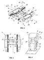
FIG. 2 is a perspective view of a detail of the surgical table ofFIG. 1 ; -
FIG. 3 is a top view of the detail ofFIG. 1 ; -
FIG. 4 is a perspective view of the load-bearing column of a surgical table of the invention, which is partially open to provide an inside view thereof; -
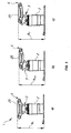
FIGS. 5a, b, c are side views of a surgical table of the invention in three different operating conditions, with the tabletop in the horizontal position; -
FIGS. 6 a, b, c are side views of a surgical table of the invention in two more operating conditions, with the tabletop in a tilted position. - Referring to the above figures, the surgical table of the invention, generally designated by numeral 1, may be used to adapt the position of a patient to a given surgical procedure or diagnostic examination.
- In the latter case, the table 1 may be used in combination with suitable diagnostic apparatus, e.g. for X-ray imaging, not shown because they are known per se.
- According to the invention, the surgical table, as shown in
FIG. 1 , comprises a floor-standing load-bearingcolumn 2 having a substantially conicalupper head 3 that defines a substantially vertical axis of symmetry W, atabletop 4 mounted to thehead 3, guide means 5 for guiding thetabletop 4 along a longitudinal plane of symmetry π passing through the vertical axis W. - The guide means 5 include a
curved guide 6 associated with thecolumn 2 when thetabletop 4 is mounted thereon, and aslide 7 movable on theguide 6. First actuator means 8 are provided, which operate on theslide 7 to cause motion thereof along thecurved guide 6. - According to a peculiar feature of the invention, the
curved guide 6 is designed for attachment to thehead 3 and theslide 7 is rigidly connected to thetabletop 4 and locked against rotation relative thereto. The first actuator means 8 are in turn removably mounted to thehead 3 to cause theslide 7 to move relative to theguide 6. - The
guide 6 may be fixedly ore movably attached to thehead 3 of thecolumn 2. - As shown in
FIG. 2 and FIG. 3 , the guide may include a pair oflateral supports 9, 9' each having a substantially cylindrical upwardly concave top surface 10, which are disposed symmetrically about the longitudinal plane of symmetry π. - Preferably, the
slide 7 may include a pair of arched elements 11, 11', each having abottom surface 12, 12' complementary in shape to the top surface 10 of thecorresponding support 9, 9', for causing rotation of thetabletop 4 at the same time as the arched elements 11, 11' slide within thelateral supports 9, 9' of theguide 6. - Also, the first actuator means 8 may include one or more
kinematic pairs 13 located at the ends of a first motorizeddrive shaft 14, having a first transverse axis X, which is rotatably mounted to theguide 6. Theshaft 14 may be rotated by amotor 16, which is coupled to the shaft through a gearmotor, not shown. - According to the preferred non exclusive configuration of the invention as shown in the figures, the
kinematic pairs 13 may be each formed of a pair ofgear wheels 17, 17' integral with theshaft 14, and located at its transverse ends, for meshing with correspondingcurved racks 18, 18' formed on each of thetop surfaces 15, 15' of the arched elements 11, 11'. - Nonetheless, the
kinematic pairs 13 may have other configurations, not shown, and may be each formed, for instance, of a pair of substantially smooth rolling surfaces respectively associated with theshaft 14 and the arched elements 11, 11', without departure from the scope of the present invention. - Advantageously, the surgical table 1 of the invention may have a modular construction, with the
tabletop 4 being composed of a central module for supporting one part of the patient body, such as the pelvis, and end modules, not shown, articulated to the longitudinal ends, and designed to support the rest of the body, such as the torso and the legs. - Furthermore, the relative tilt of each of the end modules relative to the central module may be independently adjusted to cause the
tabletop 4, and hence the patient body, to assume the most appropriate configuration for any type of surgery or examination. - According to the invention, the
slide 7 is rigidly connected to the central module, which corresponds to thewhole tabletop 4 in the figures, and its arched elements 11, 11' have substantially the same longitudinal extension ℓ as the latter. - Furthermore, the
guide 6 may be coupled, preferably in a one-piece construction, to a pair of downwardly-directedinterface elements 19, 19', which are located at each arched element 11, 11', symmetrically about the longitudinal plane π. - Each
interface element 19, 19' has a specially shapedconcave surface 20, 20' which is designed to be removably engaged by a correspondinglateral projection 21, 21', complementary in shape to thehead 3, so that theguide 6 can be integrally joined to thelateral projections 21, 21' of thehead 3, and the central module of thetabletop 4 is allowed to fit the motion of the latter. - For this purpose, the
lateral projections 21, 21' may be hinged to thecolumn 2 and thehead 3 about a second transverse axis X' substantially parallel to the first axis X. - The particular connection between the
guide 6 and thecolumn 2 allows for easy removal of the assembly composed of theguide 6, theslide 7 and thetabletop 4 from thecolumn 2, thereby allowing thetabletop 4 to be transported from one department to the other, e.g. on carriages, not shown because of commonly known fabrication. - Furthermore, the guide means 5 may be removably associated with the
column 2 while being integral with thetabletop 4, thereby allowing the use ofstandard columns 2 adapted for connection to tabletops of different construction. - Also, second actuator means 22 may be provided, which are kinematically connected to the
head 3 for adjusting the tilt of thetabletop 4 relative to a longitudinal axis Y substantially perpendicular to the vertical axis W, with thetabletop 4 in the horizontal position. - Third actuator means may be also provided, which are not visible because they are located in the
head 3, for causing translation of thehead 3 in a substantially vertical direction defined by the vertical axis W, to cause height adjustment of thetabletop 4. - The second 22 and third actuator means may be as disclosed in patent
EP1032350 , by the applicant hereof. For example, the second actuator means 22 may include a pair of substantially verticaltelescopic jacks 24, 24', arranged symmetrically about the longitudinal plane π, as shown inFIG. 4 . - Thus, by separately driving the
jacks 24, 24' using suitable mechanisms of commonly known fabrication, the tilt of thehead 3 and hence of thetabletop 4 may be adjusted relative to the longitudinal plane of symmetry π. - On the other hand, oscillation of the
lateral projections 21, 21' of thehead 2, for tilting thetabletop 4 relative to the horizontal plane defined thereby, is obtained using a special linkage located within thehead 3, which is also not shown because it is known per se. - Controlled and coordinated motion of the first 8, second 22 and third actuator means, for driving the table 1 and positioning the
tabletop 4 into the various operating modes may be obtained using special control means, not shown, which include a microprocessor unit, with an appropriate computer program installed therein for actuator motion interpolation. - This allows for simultaneous control of the angular and longitudinal positions of the
central module 4 relative to thecolumn 2. Particularly, by coordinating the rotation of the second axis X' and the sliding motion of theslide 7 along thecurved guide 6, thetabletop 4 may be caused to translate in both longitudinal and vertical directions, while maintaining the horizontal position of thecentral module 4 and without ever inclining the patient. - This operating condition is shown in
FIG. 5 , in which thetabletop 4 is shown at three different heights from the floor, i.e. h1, hMIN, h2. - Particularly,
FIG. 5a shows the table 1 with thetabletop 4 in its horizontal, substantially centered position, with theprojections 21, 21' of thehead 3 having zero tilt α relative to the floor. -
FIG. 5b shows the table 1 with thetabletop 4 still in its horizontal position but translated to the right into the maximum longitudinal translation position, and with thepatient support surface 25 at a minimum height hMIN from the floor. - In this case, the rotation of the
central module 4 in the longitudinal plane of symmetry π, caused by the motion of thearched slide 7 along thecurved guide 6 was compensated for by the coordinate rotation of thelateral projections 21, 21' about the second axis X'. - The particular configuration of the guide means 6 allows the minimum height hMIN of the
support surface 25 of thetabletop 4 from the floor to be smaller than standard values obtained in surgical tables with straight guides. The difference between such minimum values will be determined by the radius of curvature r of theslide 7 and theguide 6. - A further advantage will be obtained in terms of a longer longitudinal translation of the
tabletop 4, also depending on the curvature r of the guide means 5, which eliminates any blind spots for X-ray diagnostic apparatus or the like. - The microprocessor control means cause the rotary and translational motion of the
tabletop 4 and the rotational motion of the axis X' to be simultaneous and coordinated. - The synchronism of such motions further allows the
support surface 25 of thetabletop 4 to be maintained at a constant tilt α, e.g. always horizontal, thereby making the table 1 as comfortable as possible for the patient. -
FIGS. 6a and 6b show two operating positions of the table 1 with thetabletop 4 adapted to move the patient into the Trendelenburg or reverse Trendelenburg position, with the tilt α of thesupport surface 25 relative to the transverse plane of symmetry π' being provided in the former case by the oscillation of thelateral projections 21, 21' of thehead 3 only and in the latter case by the coordinated motion of the guide means 5 and thelateral projections 21, 21'. - The displacement of the
slide 7 along theguide 6 is found to increase the tilt α of thetabletop 4 relative to the horizontal position, thereby forming an angle in a range from about 45° in the case ofFIG. 6a to about 55° or more in the case ofFIG. 6b . Higher values can be reached by increasing the longitudinal extension ℓ or decreasing the radius of curvature r of theslide 7. - The above disclosure clearly shows that the invention fulfills the intended objects and particularly meets the requirement of providing an adjustable surgical table allowing for greater longitudinal and vertical translation and rotation than surgical tables with straight guides.
- Thanks to the particular configuration of the guide means 5 and their connection with the
support tabletop 4, the table 1 will provide considerable sturdiness and allow even distribution of the patient's weight, which will make it suitable for supporting patients of very large size without affecting reliability. - The surgical table of this invention is susceptible of a number of changes and variants, all falling within the inventive scope disclosed in the appended claims. All the details thereof may be replaced by other technically equivalent parts, and the materials may vary depending on different needs, without departure from the scope of the invention.
- While the surgical table has been described with particular reference to the accompanying figures, the numerals referred to in the disclosure and claims are only used for the sake of a better intelligibility of the invention and shall not be intended to limit the claimed scope in any manner.
Claims (13)
- An adjustable surgical table, comprising:- a floor-standing load-bearing column (2) having an upper head (3) that defines a substantially vertical axis of symmetry (W);- a tabletop (4) mounted to said head (3) for patient positioning;- guide means (5) for guiding said tabletop (4) along a longitudinal plane of symmetry (π) passing through said vertical axis (W), wherein said guide means (5) comprise a curved guide (6) designed to be associated with said column (2) and a slide (7) adapted to move on said guide (6);- first actuator means (8), operating on said slide (7) to cause motion thereof along said curved guide (6);characterized in that said curvilinear guide (6) is adapted to be fixed to said head (3), and said slide (7) is rigidly connected to said tabletop (4), locked against rotation relative thereto, said first actuator means (8) being mounted to said head (3) to cause motion of said slide (7) relative to said curved guide (6).
- Surgical table as claimed in claim 1, characterized in that said curved guide (6) includes a pair of lateral supports (9, 9') having substantially cylindrical upwardly concave top surfaces (10), which are disposed symmetrically about said longitudinal plane of symmetry (π).
- Surgical table as claimed in claim 2, characterized in that said slide (7) includes a pair of arched elements (11, 11'), having bottom surfaces (12, 12') complementary in shape to said top surfaces (10) of the corresponding lateral supports (9, 9').
- Surgical table as claimed in claim 3, characterized in that said first actuator means (8) include at least one kinematic pair (13) located at one end of a motorized shaft (14), having a first transverse axis (X), which is rotatably mounted to said curved guide (6).
- Surgical table as claimed in claim 4, characterized in that said at least one kinematic pair (13) comprises at least one gear wheel (17) integral with the shaft (14), for meshing with a corresponding rack (18) formed on a corresponding top surface (15) of one of said arched elements (11, 11').
- Surgical table as claimed in claim 1, characterized in that said tabletop (4) comprises at least one central module for supporting the pelvis of the patient, end modules being articulated to its longitudinal ends, for supporting the torso and the legs of the patient respectively.
- Surgical table as claimed in claim 6, characterized in that said slide (7) is rigidly connected to said central module (4), said arched elements (11, 11') having substantially the same longitudinal extension (ℓ) as the latter.
- Surgical table as claimed in any one of the preceding claims, characterized in that said curved guide (6) is coupled to a pair of interface elements (19, 19') each having a specially shaped concave surface (20, 20') which is designed to be removably engaged by corresponding lateral projections (21, 21'), complementary in shape to said head (3), so that said guide (6) can be integrally joined to said head (3).
- Surgical table as claimed in any one of the preceding claims, characterized in that said lateral projections (21, 21') are hinged to said column (2) about a second transverse axis (X') substantially parallel to the first axis (X).
- Surgical table as claimed in any one of the preceding claims, characterized in that it further comprises second actuator means (22) kinematically linked to said lateral projections (21, 21') of said head (3) for adjusting the tilt (α) of said tabletop 4 relative to the floor.
- Surgical table as claimed in any one of the preceding claims, characterized in that it further comprises third actuator means for causing translation of said head (3) in a substantially vertical direction, for height adjustment of the tabletop (4).
- Surgical table as claimed in any one of the preceding claims, characterized in that it further comprises means for coordinated control of said first (8), second (22) and third actuator means for simultaneous control of the angular and longitudinal positions of said central module (4) relative to the column (2).
- Surgical table as claimed in claim 12, characterized in that said control means comprise a microprocessor unit with a suitable computer program installed therein.
Applications Claiming Priority (1)
| Application Number | Priority Date | Filing Date | Title |
|---|---|---|---|
| ITVI20060360 ITVI20060360A1 (en) | 2006-12-22 | 2006-12-22 | ADJUSTABLE OPERATIVE TABLE |
Publications (3)
| Publication Number | Publication Date |
|---|---|
| EP1943996A2 true EP1943996A2 (en) | 2008-07-16 |
| EP1943996A3 EP1943996A3 (en) | 2009-02-11 |
| EP1943996B1 EP1943996B1 (en) | 2014-08-06 |
Family
ID=39207081
Family Applications (1)
| Application Number | Title | Priority Date | Filing Date |
|---|---|---|---|
| EP20070024343 Active EP1943996B1 (en) | 2006-12-22 | 2007-12-14 | Tiltable operating table |
Country Status (2)
| Country | Link |
|---|---|
| EP (1) | EP1943996B1 (en) |
| IT (1) | ITVI20060360A1 (en) |
Cited By (3)
| Publication number | Priority date | Publication date | Assignee | Title |
|---|---|---|---|---|
| CN116018095A (en) * | 2020-03-12 | 2023-04-25 | 伊利克塔有限公司 | Radiotherapy apparatus for positioning a subject |
| US12453670B2 (en) | 2022-03-25 | 2025-10-28 | Mazor Robotics Ltd. | Surgical platform and trolley assembly |
| US12539244B2 (en) | 2023-05-26 | 2026-02-03 | Warsaw Orthopedic, Inc. | Surgical gantry and interface moveably interconnecting surgical table and gantry |
Family Cites Families (5)
| Publication number | Priority date | Publication date | Assignee | Title |
|---|---|---|---|---|
| DE264297C (en) * | ||||
| FR2041291A5 (en) * | 1969-04-18 | 1971-01-29 | Descamps Louis | |
| US6070281A (en) * | 1997-04-18 | 2000-06-06 | Siemens Aktiengesellschaft | Patient orientation table |
| IT1296688B1 (en) * | 1997-11-19 | 1999-07-14 | Protesi Trento Spa Off Di | MULTIFUNCTIONAL OPERATING TABLE |
| DE102005054222A1 (en) * | 2005-11-14 | 2007-05-16 | Maquet Gmbh & Co Kg | operating table |
-
2006
- 2006-12-22 IT ITVI20060360 patent/ITVI20060360A1/en unknown
-
2007
- 2007-12-14 EP EP20070024343 patent/EP1943996B1/en active Active
Non-Patent Citations (1)
| Title |
|---|
| None |
Cited By (3)
| Publication number | Priority date | Publication date | Assignee | Title |
|---|---|---|---|---|
| CN116018095A (en) * | 2020-03-12 | 2023-04-25 | 伊利克塔有限公司 | Radiotherapy apparatus for positioning a subject |
| US12453670B2 (en) | 2022-03-25 | 2025-10-28 | Mazor Robotics Ltd. | Surgical platform and trolley assembly |
| US12539244B2 (en) | 2023-05-26 | 2026-02-03 | Warsaw Orthopedic, Inc. | Surgical gantry and interface moveably interconnecting surgical table and gantry |
Also Published As
| Publication number | Publication date |
|---|---|
| EP1943996B1 (en) | 2014-08-06 |
| ITVI20060360A1 (en) | 2008-06-23 |
| EP1943996A3 (en) | 2009-02-11 |
Similar Documents
| Publication | Publication Date | Title |
|---|---|---|
| US12076281B2 (en) | Modular multi-articulated patient support system | |
| EP0844846B1 (en) | Patient support | |
| US3724004A (en) | Adjustable bed | |
| US5590429A (en) | Electrophysiology table | |
| EP2226051A2 (en) | Person-support apparatus with movable portions | |
| CN105125364A (en) | Devices for supporting and positioning patients during medical procedures | |
| CN109803621B (en) | Positionable foot portion of a medical device | |
| JP2004522482A (en) | Operating table with articulating block | |
| US12150902B2 (en) | Surgical table | |
| US6070281A (en) | Patient orientation table | |
| EP2777671A1 (en) | Patient table | |
| US20060248648A1 (en) | Treatment couch | |
| EP1943996B1 (en) | Tiltable operating table | |
| CN119384262A (en) | Interface for removably interconnecting a surgical table and a gantry | |
| US9597043B1 (en) | System and method for supporting a patient for imagery during surgery | |
| CN111329711B (en) | Dental patient chair | |
| EP4044981A1 (en) | Multi-function frame positioning device | |
| GB2566076B (en) | Surgical tables | |
| CN106667713A (en) | A dental patient chair | |
| EP0705091B1 (en) | Intensive therapy bed | |
| KR20180102990A (en) | Bed with movable frame | |
| US12539244B2 (en) | Surgical gantry and interface moveably interconnecting surgical table and gantry | |
| JP4943417B2 (en) | Examining table | |
| EP3217882B1 (en) | Radiological apparatus with a table movement system with variable angle rods | |
| WO2014114367A1 (en) | Intensive care movable bed |
Legal Events
| Date | Code | Title | Description |
|---|---|---|---|
| PUAI | Public reference made under article 153(3) epc to a published international application that has entered the european phase |
Free format text: ORIGINAL CODE: 0009012 |
|
| AK | Designated contracting states |
Kind code of ref document: A2 Designated state(s): AT BE BG CH CY CZ DE DK EE ES FI FR GB GR HU IE IS IT LI LT LU LV MC MT NL PL PT RO SE SI SK TR |
|
| AX | Request for extension of the european patent |
Extension state: AL BA HR MK RS |
|
| PUAL | Search report despatched |
Free format text: ORIGINAL CODE: 0009013 |
|
| AK | Designated contracting states |
Kind code of ref document: A3 Designated state(s): AT BE BG CH CY CZ DE DK EE ES FI FR GB GR HU IE IS IT LI LT LU LV MC MT NL PL PT RO SE SI SK TR |
|
| AX | Request for extension of the european patent |
Extension state: AL BA HR MK RS |
|
| 17P | Request for examination filed |
Effective date: 20090806 |
|
| 17Q | First examination report despatched |
Effective date: 20090908 |
|
| AKX | Designation fees paid |
Designated state(s): AT BE BG CH CY CZ DE DK EE ES FI FR GB GR HU IE IS IT LI LT LU LV MC MT NL PL PT RO SE SI SK TR |
|
| GRAP | Despatch of communication of intention to grant a patent |
Free format text: ORIGINAL CODE: EPIDOSNIGR1 |
|
| INTG | Intention to grant announced |
Effective date: 20140123 |
|
| GRAS | Grant fee paid |
Free format text: ORIGINAL CODE: EPIDOSNIGR3 |
|
| GRAA | (expected) grant |
Free format text: ORIGINAL CODE: 0009210 |
|
| AK | Designated contracting states |
Kind code of ref document: B1 Designated state(s): AT BE BG CH CY CZ DE DK EE ES FI FR GB GR HU IE IS IT LI LT LU LV MC MT NL PL PT RO SE SI SK TR |
|
| RAP1 | Party data changed (applicant data changed or rights of an application transferred) |
Owner name: OPT SURGISYSTEMS S.R.L. |
|
| REG | Reference to a national code |
Ref country code: GB Ref legal event code: FG4D |
|
| REG | Reference to a national code |
Ref country code: CH Ref legal event code: EP Ref country code: AT Ref legal event code: REF Ref document number: 680645 Country of ref document: AT Kind code of ref document: T Effective date: 20140815 |
|
| REG | Reference to a national code |
Ref country code: IE Ref legal event code: FG4D |
|
| REG | Reference to a national code |
Ref country code: DE Ref legal event code: R096 Ref document number: 602007037953 Country of ref document: DE Effective date: 20140918 |
|
| REG | Reference to a national code |
Ref country code: AT Ref legal event code: MK05 Ref document number: 680645 Country of ref document: AT Kind code of ref document: T Effective date: 20140806 |
|
| REG | Reference to a national code |
Ref country code: NL Ref legal event code: VDEP Effective date: 20140806 |
|
| REG | Reference to a national code |
Ref country code: LT Ref legal event code: MG4D |
|
| PG25 | Lapsed in a contracting state [announced via postgrant information from national office to epo] |
Ref country code: LT Free format text: LAPSE BECAUSE OF FAILURE TO SUBMIT A TRANSLATION OF THE DESCRIPTION OR TO PAY THE FEE WITHIN THE PRESCRIBED TIME-LIMIT Effective date: 20140806 Ref country code: PT Free format text: LAPSE BECAUSE OF FAILURE TO SUBMIT A TRANSLATION OF THE DESCRIPTION OR TO PAY THE FEE WITHIN THE PRESCRIBED TIME-LIMIT Effective date: 20141209 Ref country code: FI Free format text: LAPSE BECAUSE OF FAILURE TO SUBMIT A TRANSLATION OF THE DESCRIPTION OR TO PAY THE FEE WITHIN THE PRESCRIBED TIME-LIMIT Effective date: 20140806 Ref country code: GR Free format text: LAPSE BECAUSE OF FAILURE TO SUBMIT A TRANSLATION OF THE DESCRIPTION OR TO PAY THE FEE WITHIN THE PRESCRIBED TIME-LIMIT Effective date: 20141107 Ref country code: ES Free format text: LAPSE BECAUSE OF FAILURE TO SUBMIT A TRANSLATION OF THE DESCRIPTION OR TO PAY THE FEE WITHIN THE PRESCRIBED TIME-LIMIT Effective date: 20140806 Ref country code: SE Free format text: LAPSE BECAUSE OF FAILURE TO SUBMIT A TRANSLATION OF THE DESCRIPTION OR TO PAY THE FEE WITHIN THE PRESCRIBED TIME-LIMIT Effective date: 20140806 Ref country code: BG Free format text: LAPSE BECAUSE OF FAILURE TO SUBMIT A TRANSLATION OF THE DESCRIPTION OR TO PAY THE FEE WITHIN THE PRESCRIBED TIME-LIMIT Effective date: 20141106 |
|
| PG25 | Lapsed in a contracting state [announced via postgrant information from national office to epo] |
Ref country code: PL Free format text: LAPSE BECAUSE OF FAILURE TO SUBMIT A TRANSLATION OF THE DESCRIPTION OR TO PAY THE FEE WITHIN THE PRESCRIBED TIME-LIMIT Effective date: 20140806 Ref country code: IS Free format text: LAPSE BECAUSE OF FAILURE TO SUBMIT A TRANSLATION OF THE DESCRIPTION OR TO PAY THE FEE WITHIN THE PRESCRIBED TIME-LIMIT Effective date: 20141206 Ref country code: NL Free format text: LAPSE BECAUSE OF FAILURE TO SUBMIT A TRANSLATION OF THE DESCRIPTION OR TO PAY THE FEE WITHIN THE PRESCRIBED TIME-LIMIT Effective date: 20140806 Ref country code: AT Free format text: LAPSE BECAUSE OF FAILURE TO SUBMIT A TRANSLATION OF THE DESCRIPTION OR TO PAY THE FEE WITHIN THE PRESCRIBED TIME-LIMIT Effective date: 20140806 Ref country code: CY Free format text: LAPSE BECAUSE OF FAILURE TO SUBMIT A TRANSLATION OF THE DESCRIPTION OR TO PAY THE FEE WITHIN THE PRESCRIBED TIME-LIMIT Effective date: 20140806 Ref country code: LV Free format text: LAPSE BECAUSE OF FAILURE TO SUBMIT A TRANSLATION OF THE DESCRIPTION OR TO PAY THE FEE WITHIN THE PRESCRIBED TIME-LIMIT Effective date: 20140806 |
|
| PG25 | Lapsed in a contracting state [announced via postgrant information from national office to epo] |
Ref country code: DK Free format text: LAPSE BECAUSE OF FAILURE TO SUBMIT A TRANSLATION OF THE DESCRIPTION OR TO PAY THE FEE WITHIN THE PRESCRIBED TIME-LIMIT Effective date: 20140806 Ref country code: CZ Free format text: LAPSE BECAUSE OF FAILURE TO SUBMIT A TRANSLATION OF THE DESCRIPTION OR TO PAY THE FEE WITHIN THE PRESCRIBED TIME-LIMIT Effective date: 20140806 Ref country code: RO Free format text: LAPSE BECAUSE OF FAILURE TO SUBMIT A TRANSLATION OF THE DESCRIPTION OR TO PAY THE FEE WITHIN THE PRESCRIBED TIME-LIMIT Effective date: 20140806 Ref country code: EE Free format text: LAPSE BECAUSE OF FAILURE TO SUBMIT A TRANSLATION OF THE DESCRIPTION OR TO PAY THE FEE WITHIN THE PRESCRIBED TIME-LIMIT Effective date: 20140806 Ref country code: SK Free format text: LAPSE BECAUSE OF FAILURE TO SUBMIT A TRANSLATION OF THE DESCRIPTION OR TO PAY THE FEE WITHIN THE PRESCRIBED TIME-LIMIT Effective date: 20140806 |
|
| REG | Reference to a national code |
Ref country code: DE Ref legal event code: R097 Ref document number: 602007037953 Country of ref document: DE |
|
| PLBE | No opposition filed within time limit |
Free format text: ORIGINAL CODE: 0009261 |
|
| STAA | Information on the status of an ep patent application or granted ep patent |
Free format text: STATUS: NO OPPOSITION FILED WITHIN TIME LIMIT |
|
| PG25 | Lapsed in a contracting state [announced via postgrant information from national office to epo] |
Ref country code: BE Free format text: LAPSE BECAUSE OF NON-PAYMENT OF DUE FEES Effective date: 20141231 |
|
| 26N | No opposition filed |
Effective date: 20150507 |
|
| PG25 | Lapsed in a contracting state [announced via postgrant information from national office to epo] |
Ref country code: LU Free format text: LAPSE BECAUSE OF FAILURE TO SUBMIT A TRANSLATION OF THE DESCRIPTION OR TO PAY THE FEE WITHIN THE PRESCRIBED TIME-LIMIT Effective date: 20141214 |
|
| REG | Reference to a national code |
Ref country code: CH Ref legal event code: PL |
|
| REG | Reference to a national code |
Ref country code: IE Ref legal event code: MM4A |
|
| PG25 | Lapsed in a contracting state [announced via postgrant information from national office to epo] |
Ref country code: IE Free format text: LAPSE BECAUSE OF NON-PAYMENT OF DUE FEES Effective date: 20141214 Ref country code: CH Free format text: LAPSE BECAUSE OF NON-PAYMENT OF DUE FEES Effective date: 20141231 Ref country code: LI Free format text: LAPSE BECAUSE OF NON-PAYMENT OF DUE FEES Effective date: 20141231 |
|
| PG25 | Lapsed in a contracting state [announced via postgrant information from national office to epo] |
Ref country code: SI Free format text: LAPSE BECAUSE OF FAILURE TO SUBMIT A TRANSLATION OF THE DESCRIPTION OR TO PAY THE FEE WITHIN THE PRESCRIBED TIME-LIMIT Effective date: 20140806 |
|
| REG | Reference to a national code |
Ref country code: FR Ref legal event code: PLFP Year of fee payment: 9 |
|
| PG25 | Lapsed in a contracting state [announced via postgrant information from national office to epo] |
Ref country code: MC Free format text: LAPSE BECAUSE OF FAILURE TO SUBMIT A TRANSLATION OF THE DESCRIPTION OR TO PAY THE FEE WITHIN THE PRESCRIBED TIME-LIMIT Effective date: 20140806 |
|
| PG25 | Lapsed in a contracting state [announced via postgrant information from national office to epo] |
Ref country code: HU Free format text: LAPSE BECAUSE OF FAILURE TO SUBMIT A TRANSLATION OF THE DESCRIPTION OR TO PAY THE FEE WITHIN THE PRESCRIBED TIME-LIMIT; INVALID AB INITIO Effective date: 20071214 Ref country code: BE Free format text: LAPSE BECAUSE OF FAILURE TO SUBMIT A TRANSLATION OF THE DESCRIPTION OR TO PAY THE FEE WITHIN THE PRESCRIBED TIME-LIMIT Effective date: 20140806 Ref country code: TR Free format text: LAPSE BECAUSE OF FAILURE TO SUBMIT A TRANSLATION OF THE DESCRIPTION OR TO PAY THE FEE WITHIN THE PRESCRIBED TIME-LIMIT Effective date: 20140806 Ref country code: MT Free format text: LAPSE BECAUSE OF FAILURE TO SUBMIT A TRANSLATION OF THE DESCRIPTION OR TO PAY THE FEE WITHIN THE PRESCRIBED TIME-LIMIT Effective date: 20140806 |
|
| REG | Reference to a national code |
Ref country code: FR Ref legal event code: PLFP Year of fee payment: 10 |
|
| REG | Reference to a national code |
Ref country code: FR Ref legal event code: PLFP Year of fee payment: 11 |
|
| PGFP | Annual fee paid to national office [announced via postgrant information from national office to epo] |
Ref country code: GB Payment date: 20251223 Year of fee payment: 19 |
|
| PGFP | Annual fee paid to national office [announced via postgrant information from national office to epo] |
Ref country code: IT Payment date: 20251218 Year of fee payment: 19 |
|
| PGFP | Annual fee paid to national office [announced via postgrant information from national office to epo] |
Ref country code: FR Payment date: 20251230 Year of fee payment: 19 |
|
| PGFP | Annual fee paid to national office [announced via postgrant information from national office to epo] |
Ref country code: DE Payment date: 20251229 Year of fee payment: 19 |