EP1943919A2 - Multi-functional cane - Google Patents
Multi-functional cane Download PDFInfo
- Publication number
- EP1943919A2 EP1943919A2 EP07250718A EP07250718A EP1943919A2 EP 1943919 A2 EP1943919 A2 EP 1943919A2 EP 07250718 A EP07250718 A EP 07250718A EP 07250718 A EP07250718 A EP 07250718A EP 1943919 A2 EP1943919 A2 EP 1943919A2
- Authority
- EP
- European Patent Office
- Prior art keywords
- functional
- cane
- handle member
- circuit system
- expel
- Prior art date
- Legal status (The legal status is an assumption and is not a legal conclusion. Google has not performed a legal analysis and makes no representation as to the accuracy of the status listed.)
- Withdrawn
Links
Images



Classifications
-
- A—HUMAN NECESSITIES
- A45—HAND OR TRAVELLING ARTICLES
- A45B—WALKING STICKS; UMBRELLAS; LADIES' OR LIKE FANS
- A45B3/00—Sticks combined with other objects
-
- A—HUMAN NECESSITIES
- A45—HAND OR TRAVELLING ARTICLES
- A45B—WALKING STICKS; UMBRELLAS; LADIES' OR LIKE FANS
- A45B3/00—Sticks combined with other objects
- A45B3/02—Sticks combined with other objects with illuminating devices
- A45B3/04—Sticks combined with other objects with illuminating devices electrical
-
- A—HUMAN NECESSITIES
- A45—HAND OR TRAVELLING ARTICLES
- A45B—WALKING STICKS; UMBRELLAS; LADIES' OR LIKE FANS
- A45B7/00—Other sticks, e.g. of cranked shape
- A45B7/005—Other sticks, e.g. of cranked shape crank-shaped
-
- A—HUMAN NECESSITIES
- A45—HAND OR TRAVELLING ARTICLES
- A45B—WALKING STICKS; UMBRELLAS; LADIES' OR LIKE FANS
- A45B9/00—Details
- A45B9/02—Handles or heads
Definitions
- the present invention relates to a cane, and more particularly, to a multi-functional cane.
- the cane is an effective and convenient tool for walkers.
- the cane helps to ensure the safety of climbers or people walking in the countryside.
- the cane is an important tool for people who have trouble in walking.
- the cane is designed to be a mechanical structure, which focuses on helping people move around, without multi-functional applications.
- the climber can only swing the conventional mechanical cane, which merely provides some basic defense. If a climber is caught in a mountain disaster, the conventional cane cannot provide the Mayday function. Similarly, for a person who has trouble in walking, the conventional mechanical cane only helps him move around, but does not provide the function of asking for help.
- the conventional cane merely focuses on providing mechanical support, which is limited in terms of function.
- the present invention is directed to providing a multi-functional cane, which considers various safety requirements, effectively improves the effect of the cane, and thus providing the safety and first aid effects conveniently and effectively. Furthermore, the multi-functional cane provides the remote Mayday function.
- the present invention provides a multi-functional cane, which comprises a handle member, a rod member coupled to the handle member, and a multi-functional circuit system disposed in the handle member, or the rod member, or distributed in both the handle member and the rod member.
- the multi-functional circuit system includes an alarm device and an expel device.
- the multi-functional cane of the present invention combines a plurality of safety functions, which at least provides better protection for the user when being used.
- the multi-functional cane uses the wireless communication device to seek for remote help when necessary, thus effectively reducing the injury of the user.
- the cane is convenient for the user to carry along and use, and causes no inconvenience.
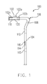
- FIG. 1 is a schematic side view of a multi-functional cane according to an embodiment of the present invention.
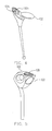
- FIGs. 2-5 are schematic stereograms of a structure of a handle member 102 according to an embodiment of the present invention.
- FIG. 6 is a schematic stereogram of a multi-functional cane according to another embodiment of the present invention.
- FIG. 7 is a schematic block diagram of the circuit of a control unit according to an embodiment of the present invention.
- the cane is an important tool for people who has trouble in walking or for climbers, and it is also a tool for walkers in rural and country areas. Generally, safety is considered when the cane is selected to be used. Usually, for example, the user can swing the cane to expel dangerous animals or even persons who attack the user.
- the conventional cane is designed to have basic functions only, without considering the safety requirements effectively.
- the present invention provides the design of a multi-functional cane. Several embodiments are given below to illustrate the present invention. However, the present invention is not limited to the embodiments given below.
- FIG. 1 is a schematic side view of a multi-functional cane according to an embodiment of the present invention.
- the multi-functional cane 100 of this embodiment includes a handle member 102, a rod member 104, and a multi-functional circuit system.
- the multi-functional circuit system includes a plurality of devices with different functions that are distributed in the rod member 104 and the handle member 102, and the rod member 104 is coupled with the handle member 102 to form a mechanical structure of the cane 100.
- the multi-functional circuit system includes, for example, an alarm device 108, an illumination device 112, an expel device 106, a power unit 110, and a control unit 102a.
- the power unit 110 provides a driving power required by the devices.
- the control unit 102a includes a control terminal part disposed on the handle member 102, so as to operate the plurality of devices of the multi-functional circuit system.
- the control unit 102a includes inner circuits (not shown in FIG. 1 ), and the control terminal part is disposed, for example, on the handle member 102, and includes, for example, a display element 102b to display operation states of corresponding devices.
- the actual circuit of the control unit 102a is shown in the block diagram of FIG. 7 . However, the circuit design of FIG. 7 is not the only choice, which can be modified depending upon actual requirements.
- the above devices with various functions are disposed, for example, within a plurality of inner spaces in the integrated structure formed by the rod member 104 and the handle member 102, and they are distributed properly.
- the illumination device 112 is designed to be close to the ground when it is used to illuminate the roads.
- the illumination device 112 is, for example, an LED light source.
- the alarm device 108 or the expel device 106 is suitable for sending alarms or expelling dangerous animals respectively, so that the two devices are designed to be disposed at the upper end of the rod member 104.
- the expel device 106 is, for example, an ultrasonic expel device used to expel animals such as wild dogs. Therefore, the expel device 106 can be disposed at the upper end of the rod member 104, for example, at the tip portion of the rod member 104.
- the control terminal of the control unit 102a is disposed on the handle member 102.
- the expel device 106 is, for example, used to expel any dangerous animal. As the acoustic frequency of animals is different from that of human beings, the generated ultrasonic waves can expel, for example, dogs, or even snakes or bees, etc..
- the main function of the alarm device 108 is to send out sounds, for example, an alarm sound for help, or further send out an alarm sound to expel hostile people. In other words, the alarm device 108 is used to provide alarm signals of sounds.
- the multi-functional circuit system of the cane of the present invention further includes a wireless device 102c, which is, for example, a wireless communication device.
- the user of the cane can contact the exterior at any time via the wireless communication device 102c. No matter the user himself/herself or people, things, or objects around the user need help, the multi-functional cane can be used to contact the exterior.
- the multi-functional circuit system of the cane further includes a positioning device 118 used to obtain a local position information.
- the positioning device 118 is, for example, a receiver of Global Positioning System (GPS), so as to obtain the local position information that can be sent out via the wireless communication device 102c when necessary.
- the multi-functional circuit system of the cane further includes a Mayday device 120, for example, to send out a Mayday signal via the wireless communication device 102c.
- the Mayday device 120 can send out a Mayday signal, and the positioning device 118 can inform the exterior about the user's local position.
- the wireless communication device 102c includes, for example, a voice device that forms an integrated structure with the handle member 102.
- the voice device includes, for example, a microphone and a speaker, etc., so as to communicate with the exterior via voice. If the user is still able to speak, the user can also seek for external help by voice.
- any one or both of the handle member 102 and the rod member 104 of the cane 100 have a storage space 114 for storing an article.
- the storage space 114 is, for example, used for storing the object 116 taken along by the user, for example, first aid medicine.
- the alarm device 108 of the cane 100 includes, for example, a sound alarm device and/or a light alarm device, which is not only simply used for expelling dangerous animals, but also used for sending local Mayday signals and so on.
- the control terminal part of the control unit 102a of the cane 100 includes a plurality of control keys disposed on the handle member 102 to facilitate controlling operations.
- the control keys also can be designed as a single selecting control key to save space.
- a selecting control key for example, the device to be controlled is selected by rotating or pressing the key, and the start, stop, or other operations are achieved by pressing the key.
- Various methods can be used to achieve the design of the selecting control key, which are not limited to that described above.
- the structure of the handle member 102 also has various designs so as to facilitate operating the devices of the cane 100.
- the structure of the handle member 102 is roughly classified into an opened handle structure or an enclosed handle structure.
- FIGs. 2-5 show several embodiments of designs of the handle member 102 of the present invention. Variations in the designs can be directly known from FIGs. 2-5 .
- the structure of the handle member 102 of the present invention is not limited to these embodiments.
- the positions where various devices are arranged also can be different. For example, an appropriate device can be disposed at position 122 in FIG. 5 .
- At least a part of the aforementioned functional devices is disposed within the inner space of the handle member 102 and/or the rod member 104 of the cane 100, which at least saves the space.
- such arrangement is not the only choice.
- FIG. 6 is a schematic stereogram of a multi-functional cane according to another embodiment of the present invention.
- the aforementioned functional devices can be further arranged in another way.
- the shape of the handle member 800 can be designed properly according to the operating modes.
- the control keys are arranged on the handle member 800, and the actual circuits are, for example, arranged in the rod member 802. Certainly, the above arrangement is also a variation in the design.
- the handle member 800 and the rod member 802 separately or integrally include an anti-shock device, a warning device, a hook, a length adjusting element, a talking/broadcasting device, a radio device, a mobile phone as at least a part of the handle member, a music playing device, and/or a automatic electric generator according to actual requirements.
- the radio device includes a volume adjusting unit and a channel searching unit, and has, for example, the FM/AM functions, or is used to receive digital broadcastings.
- the anti-shock device is, for example, disposed at the contact end of the cane.
- the warning device is, for example, an LED light source 804 for warning people or vehicles behind.
- the length adjusting element is used to adjust the length.
- the hook for example, hangs at a certain position on the cane, which is used to hook something out of reach.
- the music playing device is, for example, an MP3 player.
- the wireless device includes, for example, a wireless mobile phone, a WiFi element, and/or a ZigBee element.
- the functional devices disposed on the cane include, for example, mechanical, electronic, and electromechanical elements and the like, which are distributed or separately disposed on the handle member and/or the rod member depending upon actual requirements.
- the above descriptions are variations in the arrangement that is appreciable according to the embodiment of the present invention.
- the present invention is not limited to the above embodiments.
- a power supply 160 provides the power required by various functional circuits.
- a beeper circuit 164 is started by pressing an alarm button 162.
- an ultrasonic circuit 168 is started by pressing an expeller button 166, so as to generate the ultrasonic waves for expelling animals.
- a microprocessor or a microcontroller (MCU) 170 further controls and processes the connected relevant functional devices, e.g., a white LED circuit 172, an indicator circuit 174, and a RF circuit 176, etc.
- the RF circuit 176 also can be controlled upon receiving an input from a panel control unit 178 or a line control unit 180.
- circuit structure is only an embodiment, and the actual circuit can be adjusted and modified according to the actual design of the cane 100.
- the circuit design can be modified correspondingly, as long as the desired functions are achieved.
- the present invention is not limited to a specific circuit design.
- the multi-functional circuit system can comprise a wireless communication device.
- the multi-functional circuit system can comprise a positioning device.
- the positioning device is used to obtain a local position information, which is sent out via the wireless communication device when necessary.
- the multi-functional circuit system can comprise a Mayday device, which sends out a Mayday signal via the wireless communication device.
- the wireless communication device can comprise a voice device that forms an integrated structure with the handle member, wherein the voice device is used for communicating with the exterior, or seeks for external help by voice.
- the handle member or the rod member may have an article-storage space.
- the present invention integrates the multi-functional cane 100 through the design of the handle member and the rod member, and the user can modify the design appropriately according to local conditions. Moreover, for example, when the user needs to seek for help, the present invention effectively achieves the function of seeking for help. Therefore, as for the overall design of the cane in the present invention, the cane of the present invention has multi-functional devices on the basis of the structure of the cane 100. Thus, the cane of the present invention at least effectively enhances the safety function of the cane.
Landscapes
- Walking Sticks, Umbrellas, And Fans (AREA)
- Audible And Visible Signals (AREA)
- Rehabilitation Tools (AREA)
Abstract
Description
- The present invention relates to a cane, and more particularly, to a multi-functional cane.
- The cane is an effective and convenient tool for walkers. For example, the cane helps to ensure the safety of climbers or people walking in the countryside. Furthermore, the cane is an important tool for people who have trouble in walking.
- Conventionally, the cane is designed to be a mechanical structure, which focuses on helping people move around, without multi-functional applications.
- For example, if a climber is attacked by an animal on the mountain, the climber can only swing the conventional mechanical cane, which merely provides some basic defense. If a climber is caught in a mountain disaster, the conventional cane cannot provide the Mayday function. Similarly, for a person who has trouble in walking, the conventional mechanical cane only helps him move around, but does not provide the function of asking for help.
- Therefore, the conventional cane merely focuses on providing mechanical support, which is limited in terms of function.
- The present invention is directed to providing a multi-functional cane, which considers various safety requirements, effectively improves the effect of the cane, and thus providing the safety and first aid effects conveniently and effectively. Furthermore, the multi-functional cane provides the remote Mayday function.
- The present invention provides a multi-functional cane, which comprises a handle member, a rod member coupled to the handle member, and a multi-functional circuit system disposed in the handle member, or the rod member, or distributed in both the handle member and the rod member. The multi-functional circuit system includes an alarm device and an expel device.
- The multi-functional cane of the present invention combines a plurality of safety functions, which at least provides better protection for the user when being used. In addition, the multi-functional cane uses the wireless communication device to seek for remote help when necessary, thus effectively reducing the injury of the user. Moreover, the cane is convenient for the user to carry along and use, and causes no inconvenience.
- In order to make the aforementioned and other objects, features and advantages of the present invention comprehensible, embodiments accompanied with figures are described in detail below.
-
FIG. 1 is a schematic side view of a multi-functional cane according to an embodiment of the present invention. -
FIGs. 2-5 are schematic stereograms of a structure of ahandle member 102 according to an embodiment of the present invention. -
FIG. 6 is a schematic stereogram of a multi-functional cane according to another embodiment of the present invention. -
FIG. 7 is a schematic block diagram of the circuit of a control unit according to an embodiment of the present invention. - The cane is an important tool for people who has trouble in walking or for climbers, and it is also a tool for walkers in rural and country areas. Generally, safety is considered when the cane is selected to be used. Usually, for example, the user can swing the cane to expel dangerous animals or even persons who attack the user.
- However, the conventional cane is designed to have basic functions only, without considering the safety requirements effectively. At least based upon the above point, the present invention provides the design of a multi-functional cane. Several embodiments are given below to illustrate the present invention. However, the present invention is not limited to the embodiments given below.
-
FIG. 1 is a schematic side view of a multi-functional cane according to an embodiment of the present invention. Referring toFIG. 1 , themulti-functional cane 100 of this embodiment includes ahandle member 102, arod member 104, and a multi-functional circuit system. The multi-functional circuit system includes a plurality of devices with different functions that are distributed in therod member 104 and thehandle member 102, and therod member 104 is coupled with thehandle member 102 to form a mechanical structure of thecane 100. - The multi-functional circuit system includes, for example, an
alarm device 108, an illumination device 112, anexpel device 106, apower unit 110, and acontrol unit 102a. Thepower unit 110 provides a driving power required by the devices. As shown in the figure, thecontrol unit 102a includes a control terminal part disposed on thehandle member 102, so as to operate the plurality of devices of the multi-functional circuit system. - The
control unit 102a includes inner circuits (not shown inFIG. 1 ), and the control terminal part is disposed, for example, on thehandle member 102, and includes, for example, adisplay element 102b to display operation states of corresponding devices. The actual circuit of thecontrol unit 102a is shown in the block diagram ofFIG. 7 . However, the circuit design ofFIG. 7 is not the only choice, which can be modified depending upon actual requirements. The above devices with various functions are disposed, for example, within a plurality of inner spaces in the integrated structure formed by therod member 104 and thehandle member 102, and they are distributed properly. - For example, the illumination device 112 is designed to be close to the ground when it is used to illuminate the roads. The illumination device 112 is, for example, an LED light source. Moreover, for example, the
alarm device 108 or theexpel device 106 is suitable for sending alarms or expelling dangerous animals respectively, so that the two devices are designed to be disposed at the upper end of therod member 104. Theexpel device 106 is, for example, an ultrasonic expel device used to expel animals such as wild dogs. Therefore, theexpel device 106 can be disposed at the upper end of therod member 104, for example, at the tip portion of therod member 104. To facilitate controlling the devices, the control terminal of thecontrol unit 102a is disposed on thehandle member 102. In other words, various functional devices may be properly disposed on any appropriate position of thecane 100. Theexpel device 106 is, for example, used to expel any dangerous animal. As the acoustic frequency of animals is different from that of human beings, the generated ultrasonic waves can expel, for example, dogs, or even snakes or bees, etc.. Moreover, for example, the main function of thealarm device 108 is to send out sounds, for example, an alarm sound for help, or further send out an alarm sound to expel hostile people. In other words, thealarm device 108 is used to provide alarm signals of sounds. - In addition, for example, when the user is lost in countryside or in a mountain, and needs to seek for external help, the conventional cane cannot provide the function of contacting the exterior. However, the multi-functional circuit system of the cane of the present invention further includes a
wireless device 102c, which is, for example, a wireless communication device. The user of the cane can contact the exterior at any time via thewireless communication device 102c. No matter the user himself/herself or people, things, or objects around the user need help, the multi-functional cane can be used to contact the exterior. - Moreover, the multi-functional circuit system of the cane further includes a
positioning device 118 used to obtain a local position information. Thepositioning device 118 is, for example, a receiver of Global Positioning System (GPS), so as to obtain the local position information that can be sent out via thewireless communication device 102c when necessary. Moreover, the multi-functional circuit system of the cane further includes a Maydaydevice 120, for example, to send out a Mayday signal via thewireless communication device 102c. In particular, when the user of the cane is injured, and cannot communicate with the exterior by voice, the Maydaydevice 120 can send out a Mayday signal, and thepositioning device 118 can inform the exterior about the user's local position. - The
wireless communication device 102c includes, for example, a voice device that forms an integrated structure with thehandle member 102. The voice device includes, for example, a microphone and a speaker, etc., so as to communicate with the exterior via voice. If the user is still able to speak, the user can also seek for external help by voice. - Moreover, any one or both of the
handle member 102 and therod member 104 of thecane 100 have a storage space 114 for storing an article. The storage space 114 is, for example, used for storing theobject 116 taken along by the user, for example, first aid medicine. - The
alarm device 108 of thecane 100 includes, for example, a sound alarm device and/or a light alarm device, which is not only simply used for expelling dangerous animals, but also used for sending local Mayday signals and so on. - The control terminal part of the
control unit 102a of thecane 100 includes a plurality of control keys disposed on thehandle member 102 to facilitate controlling operations. The control keys also can be designed as a single selecting control key to save space. For such a selecting control key, for example, the device to be controlled is selected by rotating or pressing the key, and the start, stop, or other operations are achieved by pressing the key. Various methods can be used to achieve the design of the selecting control key, which are not limited to that described above. - The structure of the
handle member 102 also has various designs so as to facilitate operating the devices of thecane 100. The structure of thehandle member 102 is roughly classified into an opened handle structure or an enclosed handle structure.FIGs. 2-5 show several embodiments of designs of thehandle member 102 of the present invention. Variations in the designs can be directly known fromFIGs. 2-5 . However, the structure of thehandle member 102 of the present invention is not limited to these embodiments. Furthermore, the positions where various devices are arranged also can be different. For example, an appropriate device can be disposed atposition 122 inFIG. 5 . - It should be noted that, for example, at least a part of the aforementioned functional devices is disposed within the inner space of the
handle member 102 and/or therod member 104 of thecane 100, which at least saves the space. However, such arrangement is not the only choice. - Moreover,
FIG. 6 is a schematic stereogram of a multi-functional cane according to another embodiment of the present invention. The aforementioned functional devices can be further arranged in another way. The shape of thehandle member 800 can be designed properly according to the operating modes. The control keys are arranged on thehandle member 800, and the actual circuits are, for example, arranged in therod member 802. Certainly, the above arrangement is also a variation in the design. - Furthermore, according to the aforementioned variations in the design of the present invention, the
handle member 800 and therod member 802, for example, separately or integrally include an anti-shock device, a warning device, a hook, a length adjusting element, a talking/broadcasting device, a radio device, a mobile phone as at least a part of the handle member, a music playing device, and/or a automatic electric generator according to actual requirements. The radio device includes a volume adjusting unit and a channel searching unit, and has, for example, the FM/AM functions, or is used to receive digital broadcastings. The anti-shock device is, for example, disposed at the contact end of the cane. The warning device is, for example, anLED light source 804 for warning people or vehicles behind. The length adjusting element is used to adjust the length. The hook, for example, hangs at a certain position on the cane, which is used to hook something out of reach. The music playing device is, for example, an MP3 player. - Moreover, the wireless device includes, for example, a wireless mobile phone, a WiFi element, and/or a ZigBee element.
- According to an embodiment of the present invention, the functional devices disposed on the cane include, for example, mechanical, electronic, and electromechanical elements and the like, which are distributed or separately disposed on the handle member and/or the rod member depending upon actual requirements. The above descriptions are variations in the arrangement that is appreciable according to the embodiment of the present invention. However, the present invention is not limited to the above embodiments.
- The control circuit in the cane, for example, is shown in
FIG. 7 . Referring toFIG. 7 , apower supply 160 provides the power required by various functional circuits. For example, abeeper circuit 164 is started by pressing analarm button 162. For example, anultrasonic circuit 168 is started by pressing anexpeller button 166, so as to generate the ultrasonic waves for expelling animals. A microprocessor or a microcontroller (MCU) 170 further controls and processes the connected relevant functional devices, e.g., awhite LED circuit 172, anindicator circuit 174, and aRF circuit 176, etc. At the same time, theRF circuit 176 also can be controlled upon receiving an input from apanel control unit 178 or aline control unit 180. - It should be noted that, the aforementioned circuit structure is only an embodiment, and the actual circuit can be adjusted and modified according to the actual design of the
cane 100. The circuit design can be modified correspondingly, as long as the desired functions are achieved. The present invention is not limited to a specific circuit design. - In the multi-functional cane according to an embodiment of the present invention, the multi-functional circuit system can comprise a wireless communication device.
- In the multi-functional cane according to an embodiment of the present invention, the multi-functional circuit system can comprise a positioning device. The positioning device is used to obtain a local position information, which is sent out via the wireless communication device when necessary.
- In the multi-functional cane according to an embodiment of the present invention, the multi-functional circuit system can comprise a Mayday device, which sends out a Mayday signal via the wireless communication device.
- In the multi-functional cane according to an embodiment of the present invention, the wireless communication device can comprise a voice device that forms an integrated structure with the handle member, wherein the voice device is used for communicating with the exterior, or seeks for external help by voice.
- In the multi-functional cane according to an embodiment of the present invention, the handle member or the rod member may have an article-storage space.
- To sum up, the present invention integrates the
multi-functional cane 100 through the design of the handle member and the rod member, and the user can modify the design appropriately according to local conditions. Moreover, for example, when the user needs to seek for help, the present invention effectively achieves the function of seeking for help. Therefore, as for the overall design of the cane in the present invention, the cane of the present invention has multi-functional devices on the basis of the structure of thecane 100. Thus, the cane of the present invention at least effectively enhances the safety function of the cane. - It will be apparent to those skilled in the art that various modifications and variations can be made to the structure of the present invention without departing from the scope or spirit of the invention. In view of the foregoing, it is intended that the present invention cover modifications and variations of this invention provided they fall within the scope of the following claims and their equivalents.
Claims (21)
- A multi-functional cane, comprising:a handle member;a rod member, coupled with the handle member; anda multi-functional circuit system, disposed in the handle member or the rod member, or distributed in both the handle member and the rod member, and including an alarm device and an expel device.
- The multi-functional cane as claimed in claim 1, wherein the multi-functional circuit system further comprises a wireless communication device.
- The multi-functional cane as claimed in claim 2, wherein the multi-functional circuit system further comprises a positioning device used to obtain a local position information, and the local position information is sent out via the wireless communication device when necessary.
- The multi-functional cane as claimed in claim 2, wherein the multi-functional circuit system further comprises a Mayday device for sending out a Mayday signal via the wireless communication device.
- The multi-functional cane as claimed in claim 2, wherein the wireless communication device comprises a voice device that forms an integrated structure with the handle member, and the voice device is used for communicating with the exterior, or seeks for external help by voice.
- The multi-functional cane as claimed in claim 1, wherein the handle member or the rod member comprises a storage space.
- The multi-functional cane as claimed in claim 6, wherein the storage space stores first aid medicine.
- The multi-functional cane as claimed in claim 1, wherein the alarm device comprises at least one of a sound alarm device and a light alarm device.
- The multi-functional cane as claimed in claim 1, wherein the multi-functional circuit system further comprises an illumination device.
- The multi-functional cane as claimed in claim 1, wherein the expel device comprises an ultrasonic expel device for expelling animals.
- The multi-functional cane as claimed in claim 1, wherein the expel device comprises an ultrasonic expel device for expelling dogs.
- The multi-functional cane as claimed in claim 1, wherein the multi-functional circuit system further comprises a control unit having a control terminal part that includes a plurality of control keys and is disposed on the handle member.
- The multi-functional cane as claimed in claim 1, wherein the handle member comprises an opened handle structure or an enclosed handle structure.
- The multi-functional cane as claimed in claim 1, wherein the rod member has a plurality of inner spaces to arrange the devices.
- The multi-functional cane as claimed in claim 1, wherein the alarm device sends a Mayday signal.
- The multi-functional cane as claimed in claim 1, wherein the alarm device sends an expel signal to at least expel dangerous animals around.
- The multi-functional cane as claimed in claim 1, further comprising a power unit, a radio device, or/and a control unit, wherein the power unit provides a required driving power, and the control unit has a control terminal part disposed on the handle member to operate the devices of the multi-functional circuit system.
- The multi-functional cane as claimed in claim 1, further comprising an anti-shock device, a warning device, a hook, a length adjusting element, a talking/broadcasting functional element, a mobile phone as a part of the handle member, a music playing device, and/or an automatic electric generator.
- A multi-functional cane, comprising:a handle member;a rod member, mechanically coupled with the handle member to form a cane; anda multi-functional circuit system, distributed in the handle member and/or the rod member, and including a wireless device and a storage space.
- The multi-functional cane as claimed in claim 19, wherein the wireless device comprises a wireless communication device, a wireless mobile phone, a WiFi element, and/or a ZigBee element.
- The multi-functional cane as claimed in claim 19, further comprising an alarm device, a warning device, an illumination device, a radio device, an expel device, a positioning device, a power unit, and/or a control unit,
wherein the power unit provides a driving power required by the devices, and the control unit has a control terminal part disposed on the handle member to operate the devices of the multi-functional circuit system.
Applications Claiming Priority (1)
| Application Number | Priority Date | Filing Date | Title |
|---|---|---|---|
| US11/621,571 US20080072940A1 (en) | 2006-09-25 | 2007-01-10 | Multi-functional can |
Publications (2)
| Publication Number | Publication Date |
|---|---|
| EP1943919A2 true EP1943919A2 (en) | 2008-07-16 |
| EP1943919A3 EP1943919A3 (en) | 2010-11-17 |
Family
ID=39365705
Family Applications (1)
| Application Number | Title | Priority Date | Filing Date |
|---|---|---|---|
| EP07250718A Withdrawn EP1943919A3 (en) | 2007-01-10 | 2007-02-21 | Multi-functional cane |
Country Status (1)
| Country | Link |
|---|---|
| EP (1) | EP1943919A3 (en) |
Cited By (1)
| Publication number | Priority date | Publication date | Assignee | Title |
|---|---|---|---|---|
| US10136841B2 (en) | 2014-03-24 | 2018-11-27 | Can Mobilities, Inc. | Multi-functional smart mobility aid devices and methods of use |
Family Cites Families (7)
| Publication number | Priority date | Publication date | Assignee | Title |
|---|---|---|---|---|
| US5490825A (en) * | 1992-03-05 | 1996-02-13 | Wilkinson; William T. | Multi purpose exercise poles with many optional attachments |
| US5839461A (en) * | 1997-12-24 | 1998-11-24 | Lambeth, Jr.; Harvey F. | Protective apparatus for walkers and others |
| US6774795B2 (en) * | 2001-06-30 | 2004-08-10 | Koninklijke Philips Electroncs N.V. | Electronic assistant incorporated in personal objects |
| US6745786B1 (en) * | 2002-05-31 | 2004-06-08 | Rayneda Davis | Walking aid with supplementary features |
| US6772778B2 (en) * | 2002-10-01 | 2004-08-10 | Rik M. Morosini | Hiking stick and method of using the same |
| US20050211284A1 (en) * | 2004-03-11 | 2005-09-29 | Dooley David L | Hiking and survival staff |
| US20070000531A1 (en) * | 2005-06-21 | 2007-01-04 | Russo Paul C | Walking aid |
-
2007
- 2007-02-21 EP EP07250718A patent/EP1943919A3/en not_active Withdrawn
Cited By (1)
| Publication number | Priority date | Publication date | Assignee | Title |
|---|---|---|---|---|
| US10136841B2 (en) | 2014-03-24 | 2018-11-27 | Can Mobilities, Inc. | Multi-functional smart mobility aid devices and methods of use |
Also Published As
| Publication number | Publication date |
|---|---|
| EP1943919A3 (en) | 2010-11-17 |
Similar Documents
| Publication | Publication Date | Title |
|---|---|---|
| US20080072940A1 (en) | Multi-functional can | |
| US20070204803A1 (en) | Method and apparatus for wireless message transmission using device worn by animal | |
| CN1206615C (en) | A signalling device and communications system | |
| US20020145522A1 (en) | Buddy communicator | |
| US20090205582A1 (en) | Mobile device dog whistle | |
| ATE444696T1 (en) | INTELLIGENT FLOOR MAT | |
| JP2004013695A (en) | Portable radio terminal and reporting center device | |
| CN110050298A (en) | Wearable multifunctional personal safety equipment | |
| US20050249049A1 (en) | Personal safety device | |
| RU2013116587A (en) | MULTIFUNCTIONAL THEFT PROTECTION AGAINST | |
| US20190287383A1 (en) | Multi-Functional Personal Security System | |
| WO2011094854A1 (en) | Portable personal safety device and method | |
| US20110221605A1 (en) | Mat activated indicator | |
| CN201976574U (en) | Animal (pet) training device for calling and finding animal (pet) | |
| US8872623B2 (en) | Voice alarm | |
| US20130100989A1 (en) | Multi-functional weather alert communication key chain | |
| JP2002330807A (en) | Walking stick for blind person | |
| US10881326B1 (en) | Wearable safety device | |
| CN204132588U (en) | Multifunctional stick | |
| WO2018124941A1 (en) | Emergency alert device for people in life-threatening situations | |
| EP1296500A1 (en) | Mobile emergency call system | |
| US20130113612A1 (en) | Wireless communication system for paging, locating and/or communicating with an object | |
| KR20200073513A (en) | missing child terminal | |
| KR200410492Y1 (en) | Pedestrian traffic light guide device for the visually impaired | |
| KR20090011820U (en) | Object detector |
Legal Events
| Date | Code | Title | Description |
|---|---|---|---|
| PUAI | Public reference made under article 153(3) epc to a published international application that has entered the european phase |
Free format text: ORIGINAL CODE: 0009012 |
|
| AK | Designated contracting states |
Kind code of ref document: A2 Designated state(s): AT BE BG CH CY CZ DE DK EE ES FI FR GB GR HU IE IS IT LI LT LU LV MC NL PL PT RO SE SI SK TR |
|
| AX | Request for extension of the european patent |
Extension state: AL BA HR MK RS |
|
| PUAL | Search report despatched |
Free format text: ORIGINAL CODE: 0009013 |
|
| AK | Designated contracting states |
Kind code of ref document: A3 Designated state(s): AT BE BG CH CY CZ DE DK EE ES FI FR GB GR HU IE IS IT LI LT LU LV MC NL PL PT RO SE SI SK TR |
|
| AX | Request for extension of the european patent |
Extension state: AL BA HR MK RS |
|
| REG | Reference to a national code |
Ref country code: DE Ref legal event code: R108 |
|
| AKY | No designation fees paid | ||
| REG | Reference to a national code |
Ref country code: DE Ref legal event code: R108 Effective date: 20110714 |
|
| STAA | Information on the status of an ep patent application or granted ep patent |
Free format text: STATUS: THE APPLICATION IS DEEMED TO BE WITHDRAWN |
|
| 18D | Application deemed to be withdrawn |
Effective date: 20110524 |