EP1943756B1 - Communication systems - Google Patents
Communication systems Download PDFInfo
- Publication number
- EP1943756B1 EP1943756B1 EP06796051.8A EP06796051A EP1943756B1 EP 1943756 B1 EP1943756 B1 EP 1943756B1 EP 06796051 A EP06796051 A EP 06796051A EP 1943756 B1 EP1943756 B1 EP 1943756B1
- Authority
- EP
- European Patent Office
- Prior art keywords
- transmitter
- signal
- data
- phases
- receiver
- Prior art date
- Legal status (The legal status is an assumption and is not a legal conclusion. Google has not performed a legal analysis and makes no representation as to the accuracy of the status listed.)
- Not-in-force
Links
- 238000004891 communication Methods 0.000 title description 3
- 230000001427 coherent effect Effects 0.000 claims description 29
- 230000003287 optical effect Effects 0.000 claims description 27
- 238000000034 method Methods 0.000 claims description 9
- 230000001934 delay Effects 0.000 claims description 8
- 230000035559 beat frequency Effects 0.000 claims description 5
- 239000013307 optical fiber Substances 0.000 claims description 2
- 239000006185 dispersion Substances 0.000 description 11
- 230000005540 biological transmission Effects 0.000 description 7
- 238000010586 diagram Methods 0.000 description 5
- 239000000835 fiber Substances 0.000 description 4
- 230000003595 spectral effect Effects 0.000 description 4
- 230000008901 benefit Effects 0.000 description 3
- 230000010355 oscillation Effects 0.000 description 3
- 238000004088 simulation Methods 0.000 description 3
- 230000003111 delayed effect Effects 0.000 description 2
- 238000012545 processing Methods 0.000 description 2
- 230000000630 rising effect Effects 0.000 description 2
- 238000001228 spectrum Methods 0.000 description 2
- 230000006641 stabilisation Effects 0.000 description 2
- 230000032683 aging Effects 0.000 description 1
- 238000004458 analytical method Methods 0.000 description 1
- 238000013459 approach Methods 0.000 description 1
- 238000010009 beating Methods 0.000 description 1
- 230000008033 biological extinction Effects 0.000 description 1
- 230000015556 catabolic process Effects 0.000 description 1
- 230000000295 complement effect Effects 0.000 description 1
- 230000001010 compromised effect Effects 0.000 description 1
- 238000010276 construction Methods 0.000 description 1
- 238000006731 degradation reaction Methods 0.000 description 1
- 230000001419 dependent effect Effects 0.000 description 1
- 238000001514 detection method Methods 0.000 description 1
- 230000000694 effects Effects 0.000 description 1
- 238000005516 engineering process Methods 0.000 description 1
- 230000000116 mitigating effect Effects 0.000 description 1
- 230000005693 optoelectronics Effects 0.000 description 1
- 230000010363 phase shift Effects 0.000 description 1
- 230000010287 polarization Effects 0.000 description 1
- 230000003019 stabilising effect Effects 0.000 description 1
- 230000003068 static effect Effects 0.000 description 1
- 238000012546 transfer Methods 0.000 description 1
- 230000007704 transition Effects 0.000 description 1
- 230000010356 wave oscillation Effects 0.000 description 1
Images




Classifications
-
- H—ELECTRICITY
- H04—ELECTRIC COMMUNICATION TECHNIQUE
- H04B—TRANSMISSION
- H04B10/00—Transmission systems employing electromagnetic waves other than radio-waves, e.g. infrared, visible or ultraviolet light, or employing corpuscular radiation, e.g. quantum communication
- H04B10/50—Transmitters
Definitions
- the invention relates to processing of optical signals in communication systems.
- Coherent WDM is a technique applied to communication systems with high information spectral density (ISD).
- ISD information spectral density
- the relative optical phase of signals carried on adjacent wavelengths is fixed, such that any interference effects, which impact the channels, are also fixed, and may be beneficially used to enhance the system performance. The technique is described in the following references:
- the AMZI removes most of the power from odd numbered channels (channels 1, 3 and 5 etc) and passes most of the power from even numbered channels (channel 0, 2, 4, 6 etc).
- the second filter is designed to pass channel 4 alone and, in practice, it attenuates channels 2 and 6, and eliminates channels 0, 8, 10 etc. We are thus left with residual crosstalk from the centre of the optical spectrum of channels 2 & 6, which have passed through the peak of the AMZI, and with residual crosstalk from the edges, or wings of the optical spectrum of channels 3 and 5, which the central (high power) portions were removed by the AMZI.
- Figure A shows the eye diagrams at the output of the transmitter of such a Coherent WDM signal, aligned according to the description of the prior publications; and Figure B shows the resulting demultiplexed signal plots. It is noted that the eye height is compromised by the oscillation, which results from crosstalk.
- Figure A The characteristic features of Figure A are therefore a strongly return to zero shaped multileveled signal at the eye centre (centre of Figure A), where the amplitude of the signal varies quadratically with the number of channels transmitting a data "one".
- Figure B The characteristic features of Figure B are a residual sine wave signal at twice the channel frequency (80 GHz in this example) superimposed on the data of the demultiplexed channel. Note that the centre of the eye diagram (the decision point) aligns with a minimum point in the residual 80 GHz signal, reducing the overall performance of the system (Q factor). This is in stark contrast to Figure A, where the interference signals appear well controlled and the data.and sine wave oscillations are aligned.
- WO2004/032386 describes compensation of polarization dependent effects by processing in the electrical domain, prior to transmission.
- the invention provides a method of transmitting multiplexed signals as set out in claim 7
- the transmitter tunes the phases according to a scheme to maximise Q-factor at the receiver.
- the transmitter tunes the phases according to characteristics of a receiver filter in the optical path.
- the transmitter tunes the phases according to characteristics of optical fibre in the optical path.
- the transmitter adds a relative delay between the data signal and the beat frequency signal for odd and even channel groups to counter receiver delays introduced by a filter such as an AMZI filter.
- a 1 ⁇ 4 bit period delay is added by the transmitter.
- Figures 1 to 7 are plots illustrating aspects of operation of the invention.
- a transmitter transmits signals on multiple channels, and they are wavelength multiplexed according to Coherent WDM.
- a wavelength multiplexed signal may be generated according to different schemes, such as closely spaced sub-carrier multiplexing and indeed they may be multiplexed in the electrical domain and converted to optical according to a scheme such as Orthogonal Frequency Division Multiplexing (OFDM).
- OFDM Orthogonal Frequency Division Multiplexing
- Alignment strategies to tune the relative phases are based on the delay properties of the transmission link and the particular filters used within the receiver.
- the filter described in the prior art namely an AMZI used to demultiplex the data.
- the AMZI has a free spectral range equal to twice the channel spacing (which in turn equals the system clock frequency).
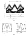
- Fig. 1 shows the output of the transmitter
- Fig. 2 shows the output of the demultiplexer, both when the transmitter is aligned according to the invention.
- this misalignment after detection is a direct consequence of the delay properties of the AMZI, which has a delay of half of the signal bit period (12.5ps for a 40 Gbit/s signal).
- the output signal comprises the interference between an un-delayed copy of the signal entering the AMZI, and a copy of the signal delayed by half of the bit period.
- the result of this interference is to impose a net delay to the rising and falling edges equal to the mean delay of the two arms, or 6.25 ps (1 ⁇ 4 of the bit period) in this example.
- the half power point of the rising edge of pulses exiting the AMZI should correspond to the interference between the "zero" level of the un-delayed copy and the "one" level of the delayed copy of pulses entering the AMZI.
- the 12.5 ps delay corresponds to one oscillation period, and so the output is a simple in phase addition of two infinite sine waves, and no net phase shift is experienced.
- the characteristic features of a Coherent WDM signal are a combination of data signals representing the information for each channel, sine wave signals representing the beating between carrier components of each channel, and residual crosstalk.
- the action of the AMZI is to alter the relative delays of the components of Coherent WDM, reducing the benefits of the alignment strategy suggested by the prior art.
- This behaviour may also be understood from the group delay characteristics of the AMZI, and the techniques of the invention may be generalised using such characteristics.
- the invention provides the following modified alignment strategy, assuming the transmitter is initially aligned as described above.
- the transmitter data signal delays and optical phases are adjusted to take into account the group delay characteristics of the total optical path between the transmitter and the detector, namely the demultiplexing filter, the transmission fibre link, and any other components, such as optical amplifiers or wavelength routers added to the link to increase its functionality, in accordance with common practice.
- the dispersion tolerance of a signal of bit rate B may be improved by a factor of N 2 by splitting the signal into N channels, each of bit rate B/N. These channels may then be transmitted over a Coherent WDM system with N channels.
- the dispersion tolerance of a 40 Gbit/s signal ( ⁇ 2-5km) may be increased close to that of a 10 Gbit/s signal (50-80km) by transmitting the data as a 5 channel Coherent WDM signal, with a bit rate of 8 Gbit/s per channel. This has several advantages of many alternative techniques.
- Coherent WDM when compared to various methods of pre-chirping the 40 Gbit/s signal, the use of Coherent WDM offers enhanced performance, whilst using lower speed and less expensive electronics and opto-electronic components. When compared to using conventional WDM technology, the use of Coherent WDM does not increase the overall spectral width of the signal.
- Fig. 5 shows, from left to right, the output of the demultiplexing filters for the centre channel with a net dispersion of -10 ps/nm, -5 ps/nm , 0 ps/nm, +5 ps/nm and +10 ps/nm. It is apparent from Fig. 5 that the nature of the interference is changing, especially as the level of dispersion increases. This is, of course, entirely due to the relative phases of the various components of the signal.
- the variation in eye width is negligible when compared to the changes in the residual 80 GHz signal and the crosstalk.
- the distortion may be broken down into changes in the relative phase of the 80 GHz beat signal, changes in the location of the residual crosstalk, and changes in the shape of the central portion of the eye.
- Coherent WDM offers the simple possibility of pre-distorting the signals to allow for the delay characteristics of the intermediate components.
- the transmission performance of a Coherent WDM signal may be enhanced by optimising the relative delays of the data signals with respect to the beat signals, and by optimising the relative optical phases of adjacent channels in order to maximise the eye opening, and minimise the crosstalk respectively.
- the success of optimising the optical phase as a function of dispersion is shown in Fig. 6 .
- up to 2 dB Q factor improvement may be achieved by optimising the relative optical phase alone, resulting in a performance very similar to the 40 Gbit/s single channel case.
- Significant phase changes of up to 1 radian ( ⁇ 60°) are required to achieve this optimum performance.
- Such Q factor improvement may be used in many ways, including, for example, the increase in loss of the link (by adding more fibre, or as a margin for ageing), or by the increase of the number of WDM channels transmitted at a fixed maximum total power.
- Fig. 7 is a plot of Penalty vs. Dispersion, showing experimental points which back up the simulation results of Figs. 4 to 6 .
- the invention is not limited to the embodiments described but may be varied in construction and detail. For example, it may be applied to optical data multiplexing schemes other than Coherent WDM.
Landscapes
- Physics & Mathematics (AREA)
- Electromagnetism (AREA)
- Engineering & Computer Science (AREA)
- Computer Networks & Wireless Communication (AREA)
- Signal Processing (AREA)
- Optical Communication System (AREA)
Description
- The invention relates to processing of optical signals in communication systems.
- Coherent WDM is a technique applied to communication systems with high information spectral density (ISD). In Coherent WDM, the relative optical phase of signals carried on adjacent wavelengths is fixed, such that any interference effects, which impact the channels, are also fixed, and may be beneficially used to enhance the system performance. The technique is described in the following references:
- 1. A. D. Ellis, F. C. Gunning, "Coherent WDM, towards > 1 bit/s/Hz information spectral density", Opto Ireland 2005 (Royal Dublin Society, Dublin, Ireland, 4-6 April 2005)
- 2. A.D.Ellis, F.C.G.Gunning, "Achievement of 1 bit/s/Hz Information Spectral Density Using Coherent WDM", Proc. OFC 2005, Paper OThR4, 2005.
- 3. A.D.Ellis, F.C.G.Gunning, "Spectral Density Enhancement using Coherent WDM", Photonics Technol. Lett. Vol. 17, No. 2, 504-506, Feb 2005.
- 4. A.D.Ellis, F.C.G.Gunning, "Filter strategies for Coherent WDM", Proc. ETOS, 26th-29th July, Cork, 2004.
- In these prior publications, it is assumed that the phase difference between the signals is zero, and that optical filters used to extract (demultiplex) the signal carried by a particular wavelength efficiently reject distantly spaced wavelengths. For closely spaced signals, Coherent WDM anticipates that some power from adjacent channels will also pass this demultiplexing filter, and it controls the phase of the resulting crosstalk to maximise the system performance. In particular, when an asymmetric Mach Zehnder interferometer (AMZI) is used to eliminate most of the power from the nearest neighbour channels, and a broadband filter is used to eliminate most distant channels, a portion of the power from the nearest neighbours leaks through the filters. For example, if looking at channel 4, the AMZI removes most of the power from odd numbered channels (
channels channel channels channels channels 2 & 6, which have passed through the peak of the AMZI, and with residual crosstalk from the edges, or wings of the optical spectrum ofchannels channels channels - Secondly, whilst the simple argument for Coherent WDM states that the eye is opened by coherent interference between adjacent channels, this is not strictly true after the AMZI filter has partially removed the nearest neighbour channels. What remains from the spectral wings of the adjacent channels is still well controlled interference, due to the coherent nature of the signals, but the precise nature of the interference is much more complicated to analyse.
- Consider by way of example a 280 Gbit/s Coherent WDM system, generated using seven 40 Gbit/s channels. Figure A shows the eye diagrams at the output of the transmitter of such a Coherent WDM signal, aligned according to the description of the prior publications; and
Figure B shows the resulting demultiplexed signal plots. It is noted that the eye height is compromised by the oscillation, which results from crosstalk. - It may be inferred from the prior art that there are several different phases, or delays, which need to be optimised within the transmitter of this system. In order to obtain the signal of Figure A, the transmitter should be aligned as follows:
- 1. Arranging for the data signal delays on the even numbered channels to align with, for example, the 80 GHz beat frequency (or twice the data rate) between the even numbered comb lines, such that the eye crossing of each data signal is aligned to the maximum of one of the 80 GHz cycles, similarly (but harder to measure) the eye opening.
- 2. Aligning the data delay for odd numbered channels to the odd numbered comb in the same way.
- 3. Aligning the relative delay between even and odd numbered channels such that all of the eye crossings are aligned.
- 4. Stabilising the optical phase and signal polarisations such that the interference signal is maximised. Ideally, the intensity at the eye crossing should vary quadratically with the level number; in a non-coherent system it would vary linearly with level number.
- The characteristic features of Figure A are therefore a strongly return to zero shaped multileveled signal at the eye centre (centre of Figure A), where the amplitude of the signal varies quadratically with the number of channels transmitting a data "one". A complementary area between adjacent eye centres, where transitions between data "ones" and data "zeros" for all of the channels occur, appears as a shaped burst of noise.
- However, when a system is aligned according to this strategy, giving the clearest eye opening at the transmitter, and is then demultiplexed using an AMZI, or another filter with a similar transfer function, the received eye diagram (
Figure B ) shows significant distortion. There is therefore a need for enhanced alignment techniques to achieve performance improvements, such as when an AMZI is used as a receiver. In particular, the transmitter alignment should be pre-distorted to match characteristics of the receiver. - The characteristic features of
Figure B are a residual sine wave signal at twice the channel frequency (80 GHz in this example) superimposed on the data of the demultiplexed channel. Note that the centre of the eye diagram (the decision point) aligns with a minimum point in the residual 80 GHz signal, reducing the overall performance of the system (Q factor). This is in stark contrast to Figure A, where the interference signals appear well controlled and the data.and sine wave oscillations are aligned. -
US2004/0197103 describes compensation of nonlinearity-induced signal distortions. -
WO2004/032386 describes compensation of polarization dependent effects by processing in the electrical domain, prior to transmission. - According to the invention, there is provided a data transmitter as set out in
claim 1 - In another aspect, the invention provides a method of transmitting multiplexed signals as set out in claim 7
- In one embodiment, the transmitter tunes the phases according to a scheme to maximise Q-factor at the receiver.
- In one embodiment, the transmitter tunes the phases according to characteristics of a receiver filter in the optical path.
- In a further embodiment, the transmitter tunes the phases according to characteristics of optical fibre in the optical path.
- In one embodiment, the transmitter adds a relative delay between the data signal and the beat frequency signal for odd and even channel groups to counter receiver delays introduced by a filter such as an AMZI filter.
- In one embodiment, a ¼ bit period delay is added by the transmitter.
- The invention will be more clearly understood from the following description of some embodiments thereof, given by way of example only with reference to the accompanying drawings in which:-
-
Figures 1 to 7 are plots illustrating aspects of operation of the invention. - In the invention, a transmitter transmits signals on multiple channels, and they are wavelength multiplexed according to Coherent WDM. In other embodiments such a wavelength multiplexed signal may be generated according to different schemes, such as closely spaced sub-carrier multiplexing and indeed they may be multiplexed in the electrical domain and converted to optical according to a scheme such as Orthogonal Frequency Division Multiplexing (OFDM). Equality of the received signals is very much enhanced by tuning the relative phases of neighbouring channels according to delay characteristics of the optical path..
- Alignment strategies to tune the relative phases are based on the delay properties of the transmission link and the particular filters used within the receiver. By way of example, we consider the filter described in the prior art, namely an AMZI used to demultiplex the data. For typical operation in a Coherent WDM system, the AMZI has a free spectral range equal to twice the channel spacing (which in turn equals the system clock frequency).
Fig. 1 shows the output of the transmitter, andFig. 2 shows the output of the demultiplexer, both when the transmitter is aligned according to the invention. - Referring again to
Figure B , signal features are as follows: - the data pattern of the target channel, two periods are shown, with a left and a right eye diagram,
- an oscillation of the "one" level at 80 GHz,
- residual crosstalk,
- It is our understanding that this misalignment after detection is a direct consequence of the delay properties of the AMZI, which has a delay of half of the signal bit period (12.5ps for a 40 Gbit/s signal). The output signal comprises the interference between an un-delayed copy of the signal entering the AMZI, and a copy of the signal delayed by half of the bit period. For a data signal, the result of this interference is to impose a net delay to the rising and falling edges equal to the mean delay of the two arms, or 6.25 ps (¼ of the bit period) in this example. This is because the half power point of the rising edge of pulses exiting the AMZI should correspond to the interference between the "zero" level of the un-delayed copy and the "one" level of the delayed copy of pulses entering the AMZI. In the case of an 80 GHz sine wave signal, the 12.5 ps delay corresponds to one oscillation period, and so the output is a simple in phase addition of two infinite sine waves, and no net phase shift is experienced. As we have seen above, the characteristic features of a Coherent WDM signal are a combination of data signals representing the information for each channel, sine wave signals representing the beating between carrier components of each channel, and residual crosstalk. Thus the action of the AMZI is to alter the relative delays of the components of Coherent WDM, reducing the benefits of the alignment strategy suggested by the prior art. This behaviour may also be understood from the group delay characteristics of the AMZI, and the techniques of the invention may be generalised using such characteristics.
- In this example, the invention provides the following modified alignment strategy, assuming the transmitter is initially aligned as described above.
- 1. At the transmitter, add a relative delay of ¼ bit period between each data signal and the beat frequency signal for the odd and even channel groups, to counter the receiver side delays introduced by the AMZI. This corresponds to aligning the transmitter such that the eye crossing corresponds to a minimum of the 80 GHz beat signal. In order to obtain a stable phase relationship between adjacent channels the 80 GHz tone is set to a particular value. Any harmonics or sub-harmonics will similarly vary with phase and therefore can also be used as an error signal for a phase stabilisation circuit. The phase stabilisation circuit in the transmitter therefore can maintain a desired stable optimum phase alignment between neighbouring channels.
- 2. In order to control the exact location of residual (static) interference terms after the AMZI demultiplexer the relative optical phases within the transmitter are adjusted from their initial values to pre-compensate for the expected delay characteristics of the transmission link and optical receiver.
- This gives rise to an apparent degradation in the eye diagram at the transmitter, as shown in
Fig. 1 .However, after demultiplexing, the eye pattern, and hence system performance, is significantly improved, as is clear fromFig. 2 . - This realignment of the phases of the data signals and the residual 80 GHz beat signal is confirmed in
Fig. 3 , a numerical simulation, where only even numbered channels are considered, but a similar AMZI is used within the receiver. Common features between this simulation and the observed transmitter and demultiplexed eye patterns ofFigs. 1 and2 are apparent. - In general terms, the transmitter data signal delays and optical phases are adjusted to take into account the group delay characteristics of the total optical path between the transmitter and the detector, namely the demultiplexing filter, the transmission fibre link, and any other components, such as optical amplifiers or wavelength routers added to the link to increase its functionality, in accordance with common practice.
- When a Coherent WDM signal is transmitted over long lengths of fibre, many experts in the telecommunications field would expect that such transmission would degrade, or even completely destroy, the phase relationship between the adjacent channels, eliminating any benefit from Coherent WDM. We have demonstrated that this is not the case, and the relative optical phases between the channels are largely preserved on transmission, allowing error free performance over 80 km of dispersion compensated fibre. Subsequent numerical modelling, as shown in
Fig. 4 , shows that the dispersion tolerance of a Coherent WDM system approaches the performance of a single wavelength signal of similar characteristics (with the same data rate on that wavelength as one of the Coherent WDM channels, the same rise time, extinction ratio etc). For the example considered, each modulator is driven at 42.6 Gbit/s, giving a total data rate of approximately 298 Gbit/s, and the phases within the transmitter are aligned for 0 ps/nm dispersion (back to back). - It is well known that the dispersion tolerance of a signal of bit rate B may be improved by a factor of N2 by splitting the signal into N channels, each of bit rate B/N. These channels may then be transmitted over a Coherent WDM system with N channels. For example, the dispersion tolerance of a 40 Gbit/s signal (∼ 2-5km) may be increased close to that of a 10 Gbit/s signal (50-80km) by transmitting the data as a 5 channel Coherent WDM signal, with a bit rate of 8 Gbit/s per channel. This has several advantages of many alternative techniques. For example, when compared to various methods of pre-chirping the 40 Gbit/s signal, the use of Coherent WDM offers enhanced performance, whilst using lower speed and less expensive electronics and opto-electronic components. When compared to using conventional WDM technology, the use of Coherent WDM does not increase the overall spectral width of the signal.
- The impact of dispersion on a Coherent WDM system is illustrated in
Fig. 5 , below which shows, from left to right, the output of the demultiplexing filters for the centre channel with a net dispersion of -10 ps/nm, -5 ps/nm , 0 ps/nm, +5 ps/nm and +10 ps/nm. It is apparent fromFig. 5 that the nature of the interference is changing, especially as the level of dispersion increases. This is, of course, entirely due to the relative phases of the various components of the signal. Indeed between -5 ps/nm and +5 ps/nm the variation in eye width is negligible when compared to the changes in the residual 80 GHz signal and the crosstalk. The distortion may be broken down into changes in the relative phase of the 80 GHz beat signal, changes in the location of the residual crosstalk, and changes in the shape of the central portion of the eye. - Coherent WDM offers the simple possibility of pre-distorting the signals to allow for the delay characteristics of the intermediate components. We thus propose that the transmission performance of a Coherent WDM signal may be enhanced by optimising the relative delays of the data signals with respect to the beat signals, and by optimising the relative optical phases of adjacent channels in order to maximise the eye opening, and minimise the crosstalk respectively. The success of optimising the optical phase as a function of dispersion is shown in
Fig. 6 . - In this case, up to 2 dB Q factor improvement may be achieved by optimising the relative optical phase alone, resulting in a performance very similar to the 40 Gbit/s single channel case. Significant phase changes of up to 1 radian (∼60°) are required to achieve this optimum performance. Such Q factor improvement may be used in many ways, including, for example, the increase in loss of the link (by adding more fibre, or as a margin for ageing), or by the increase of the number of WDM channels transmitted at a fixed maximum total power.
-
Fig. 7 is a plot of Penalty vs. Dispersion, showing experimental points which back up the simulation results ofFigs. 4 to 6 . - Similar improvements may also be expected by optimising the phase between the data signals and the 80 GHz beat signals.
- The invention is not limited to the embodiments described but may be varied in construction and detail. For example, it may be applied to optical data multiplexing schemes other than Coherent WDM.
Claims (8)
- A data transmitter for transmitting wavelength multiplexed signals on an optical path to a receiver according to Coherent WDM in which relative optical phases of signals carried on adjacent wavelengths are preserved, characterized in that the transmitter is adapted to tune the relative signal data and signal carrier phases between signals according to delay characteristics of the optical path.
- A data transmitter as claimed in claim 1, wherein the transmitter is adapted to tune the phases according to a scheme to maximise Q-factor at the receiver.
- A data transmitter as claimed in either of claims 1 or 2, wherein the transmitter is adapted to tune the phases according to characteristics of a receiver filter in the optical path.
- A data transmitter as claimed in any preceding claim, wherein the transmitter is adapted to tune the phases according to characteristics of optical fibre in the optical path.
- A data transmitter as claimed in any preceding claim, wherein the transmitter is adapted to add a relative delay between the data signal and the beat frequency signal for odd and even channel groups to counter receiver delays introduced by a filter such as an AMZI filter.
- A data transmitter as claimed in claim 5, wherein a ¼ bit period delay is added.
- A method of transmitting multiplexed signals on an optical path from a transmitter to a receiver according to Coherent WDM, in which relative optical phases of signals carried on adjacent wavelengths are preserved, characterized in that the transmitter tunes the relative signal data and signal carrier phases between signals according to delay characteristics of the optical path.
- A method as claimed in claim 7, wherein the transmitter tunes the phases according to a scheme to maximise Q-factor at the receiver.
Applications Claiming Priority (2)
| Application Number | Priority Date | Filing Date | Title |
|---|---|---|---|
| IE20050693 | 2005-10-13 | ||
| PCT/IE2006/000109 WO2007043032A1 (en) | 2005-10-13 | 2006-10-11 | Communication systems |
Publications (2)
| Publication Number | Publication Date |
|---|---|
| EP1943756A1 EP1943756A1 (en) | 2008-07-16 |
| EP1943756B1 true EP1943756B1 (en) | 2014-03-12 |
Family
ID=37492527
Family Applications (1)
| Application Number | Title | Priority Date | Filing Date |
|---|---|---|---|
| EP06796051.8A Not-in-force EP1943756B1 (en) | 2005-10-13 | 2006-10-11 | Communication systems |
Country Status (4)
| Country | Link |
|---|---|
| US (1) | US20090074416A1 (en) |
| EP (1) | EP1943756B1 (en) |
| JP (1) | JP2009512312A (en) |
| WO (1) | WO2007043032A1 (en) |
Families Citing this family (5)
| Publication number | Priority date | Publication date | Assignee | Title |
|---|---|---|---|---|
| EP2173043B1 (en) | 2008-10-06 | 2013-07-03 | University College Cork | Integrated optical comb source system and method |
| EP2202931A1 (en) | 2008-12-23 | 2010-06-30 | University College Cork | Method and system for increasing spectral density in a communications network |
| WO2015022034A1 (en) * | 2013-08-16 | 2015-02-19 | Telefonaktiebolaget L M Ericsson (Publ) | A method and apparatus for superchannel tuning |
| CN104486026B (en) * | 2014-11-28 | 2018-04-03 | 中国电子科技集团公司第二十九研究所 | A kind of method and device of multichannel microwave phase stabilization transmission |
| CN105099566A (en) * | 2015-06-30 | 2015-11-25 | 西安电子科技大学 | Device for generating millimeter wave signals by using double independent tunable fiber lasers |
Family Cites Families (9)
| Publication number | Priority date | Publication date | Assignee | Title |
|---|---|---|---|---|
| US4077701A (en) * | 1976-06-02 | 1978-03-07 | International Telephone And Telegraph Corporation | Method and arrangements for dispersion equalization of optical fiber transmission lines |
| JPH118590A (en) * | 1997-04-25 | 1999-01-12 | Oki Electric Ind Co Ltd | Optical transmission system and supervisory and control method therefor |
| GB9712020D0 (en) * | 1997-06-09 | 1997-08-06 | Northern Telecom Ltd | Equalisation, pulse shaping and regeneration of optical signals |
| US6124960A (en) * | 1997-09-08 | 2000-09-26 | Northern Telecom Limited | Transmission system with cross-phase modulation compensation |
| US6577423B1 (en) * | 1999-09-17 | 2003-06-10 | Corvis Corporation | Optical transmission systems, optical receivers, and receiving methods |
| JP4181742B2 (en) * | 2000-12-13 | 2008-11-19 | 日本電気株式会社 | Cross-phase modulation suppressor and optical communication system in wavelength division multiplexing optical transmission system |
| ATE472205T1 (en) * | 2002-04-15 | 2010-07-15 | Ericsson Telefon Ab L M | PHASE MODULATION FOR THE OPTICAL TRANSMISSION SYSTEM |
| WO2004032386A1 (en) | 2002-10-03 | 2004-04-15 | Nortel Networks Limited | Electrical domain mitigation of polarization dependent effects in an optical communications system |
| US7756421B2 (en) * | 2002-10-03 | 2010-07-13 | Ciena Corporation | Electrical domain compensation of non-linear effects in an optical communications system |
-
2006
- 2006-10-11 WO PCT/IE2006/000109 patent/WO2007043032A1/en not_active Ceased
- 2006-10-11 EP EP06796051.8A patent/EP1943756B1/en not_active Not-in-force
- 2006-10-11 JP JP2008535178A patent/JP2009512312A/en active Pending
- 2006-10-11 US US12/083,499 patent/US20090074416A1/en not_active Abandoned
Also Published As
| Publication number | Publication date |
|---|---|
| JP2009512312A (en) | 2009-03-19 |
| WO2007043032A1 (en) | 2007-04-19 |
| IE20060749A1 (en) | 2007-06-13 |
| US20090074416A1 (en) | 2009-03-19 |
| EP1943756A1 (en) | 2008-07-16 |
Similar Documents
| Publication | Publication Date | Title |
|---|---|---|
| US6317243B1 (en) | Optical upconverter apparatuses, methods and systems | |
| US5946119A (en) | Wavelength division multiplexed system employing optimal channel modulation | |
| US6456750B1 (en) | Optical transmission apparatuses, methods, and systems | |
| JP4657616B2 (en) | Multi-channel optical equalizer to reduce intersymbol interference | |
| JP2011041307A (en) | Multi-channel optical equalizer for intersymbol interference mitigation | |
| US6396607B1 (en) | Multi-wavelength all-optical regenerators (MARS) | |
| Olsson et al. | WDM to OTDM multiplexing using an ultrafast all-optical wavelength converter | |
| WO2001071959A2 (en) | Method and system of transmitting optical signals generated by multi-line sources via wdm optical network | |
| US6404526B2 (en) | WDM system that uses nonlinear temporal gratings | |
| US20090074416A1 (en) | Communication Systems | |
| Gunning et al. | Dispersion tolerance of coherent WDM | |
| Chraplyvy | High-capacity lightwave transmission experiments | |
| US6384945B1 (en) | Nonlinear temporal grating as a new optical solitary wave | |
| Wang et al. | A low complexity coherent 16× 400 Gbit/s 4SC-16QAM DSCM system with precise transceiver IQ skew compensation and simplified equalization | |
| Shahpari et al. | Fully coherent self-homodyne bi-directional enhanced performance PON | |
| Koch et al. | Silicon photonics DWDM NLFT soliton transmitter | |
| IE84766B1 (en) | Communication systems | |
| Ellis et al. | Coherent WDM: The achievement of high information spectral density through phase control within the transmitter | |
| EP2541969B1 (en) | Optical packet switch | |
| Abdo et al. | Adaptive Pre-Compensation of ROADMs in Coherent Optical Transponders | |
| AU et al. | 4× 4 MIMO Fiber-Wireless System with RoF Transmission Capability | |
| Ng et al. | Characterisation of a parallel optical all pass filter for chromatic dispersion equalisation in 10 Gb/s system | |
| Hinz et al. | Polarization Multiplexed 2× 20Gbit/s RZ Transmission using Interference Detection | |
| Nahas | 50 ghz spaced 25× 40 gbit/s wdm transmission over 560 km using smf-based large effective area fiber (leaf) | |
| Ellis et al. | Coherent WDM, toward> 1 bit/s/Hz information spectral density |
Legal Events
| Date | Code | Title | Description |
|---|---|---|---|
| PUAI | Public reference made under article 153(3) epc to a published international application that has entered the european phase |
Free format text: ORIGINAL CODE: 0009012 |
|
| 17P | Request for examination filed |
Effective date: 20080416 |
|
| AK | Designated contracting states |
Kind code of ref document: A1 Designated state(s): AT BE BG CH CY CZ DE DK EE ES FI FR GB GR HU IE IS IT LI LT LU LV MC NL PL PT RO SE SI SK TR |
|
| 17Q | First examination report despatched |
Effective date: 20100601 |
|
| DAX | Request for extension of the european patent (deleted) | ||
| REG | Reference to a national code |
Ref country code: DE Ref legal event code: R079 Ref document number: 602006040664 Country of ref document: DE Free format text: PREVIOUS MAIN CLASS: H04B0010145000 Ipc: H04B0010500000 |
|
| RIC1 | Information provided on ipc code assigned before grant |
Ipc: H04B 10/50 20130101AFI20130822BHEP |
|
| GRAP | Despatch of communication of intention to grant a patent |
Free format text: ORIGINAL CODE: EPIDOSNIGR1 |
|
| INTG | Intention to grant announced |
Effective date: 20130930 |
|
| GRAS | Grant fee paid |
Free format text: ORIGINAL CODE: EPIDOSNIGR3 |
|
| GRAA | (expected) grant |
Free format text: ORIGINAL CODE: 0009210 |
|
| AK | Designated contracting states |
Kind code of ref document: B1 Designated state(s): AT BE BG CH CY CZ DE DK EE ES FI FR GB GR HU IE IS IT LI LT LU LV MC NL PL PT RO SE SI SK TR |
|
| REG | Reference to a national code |
Ref country code: GB Ref legal event code: FG4D |
|
| REG | Reference to a national code |
Ref country code: CH Ref legal event code: EP |
|
| REG | Reference to a national code |
Ref country code: AT Ref legal event code: REF Ref document number: 656889 Country of ref document: AT Kind code of ref document: T Effective date: 20140315 |
|
| REG | Reference to a national code |
Ref country code: IE Ref legal event code: FG4D |
|
| REG | Reference to a national code |
Ref country code: DE Ref legal event code: R096 Ref document number: 602006040664 Country of ref document: DE Effective date: 20140424 |
|
| REG | Reference to a national code |
Ref country code: NL Ref legal event code: VDEP Effective date: 20140312 |
|
| PG25 | Lapsed in a contracting state [announced via postgrant information from national office to epo] |
Ref country code: LT Free format text: LAPSE BECAUSE OF FAILURE TO SUBMIT A TRANSLATION OF THE DESCRIPTION OR TO PAY THE FEE WITHIN THE PRESCRIBED TIME-LIMIT Effective date: 20140312 |
|
| REG | Reference to a national code |
Ref country code: AT Ref legal event code: MK05 Ref document number: 656889 Country of ref document: AT Kind code of ref document: T Effective date: 20140312 |
|
| REG | Reference to a national code |
Ref country code: LT Ref legal event code: MG4D |
|
| PG25 | Lapsed in a contracting state [announced via postgrant information from national office to epo] |
Ref country code: FI Free format text: LAPSE BECAUSE OF FAILURE TO SUBMIT A TRANSLATION OF THE DESCRIPTION OR TO PAY THE FEE WITHIN THE PRESCRIBED TIME-LIMIT Effective date: 20140312 Ref country code: CY Free format text: LAPSE BECAUSE OF FAILURE TO SUBMIT A TRANSLATION OF THE DESCRIPTION OR TO PAY THE FEE WITHIN THE PRESCRIBED TIME-LIMIT Effective date: 20140312 Ref country code: SE Free format text: LAPSE BECAUSE OF FAILURE TO SUBMIT A TRANSLATION OF THE DESCRIPTION OR TO PAY THE FEE WITHIN THE PRESCRIBED TIME-LIMIT Effective date: 20140312 |
|
| PG25 | Lapsed in a contracting state [announced via postgrant information from national office to epo] |
Ref country code: LV Free format text: LAPSE BECAUSE OF FAILURE TO SUBMIT A TRANSLATION OF THE DESCRIPTION OR TO PAY THE FEE WITHIN THE PRESCRIBED TIME-LIMIT Effective date: 20140312 |
|
| PG25 | Lapsed in a contracting state [announced via postgrant information from national office to epo] |
Ref country code: CZ Free format text: LAPSE BECAUSE OF FAILURE TO SUBMIT A TRANSLATION OF THE DESCRIPTION OR TO PAY THE FEE WITHIN THE PRESCRIBED TIME-LIMIT Effective date: 20140312 Ref country code: RO Free format text: LAPSE BECAUSE OF FAILURE TO SUBMIT A TRANSLATION OF THE DESCRIPTION OR TO PAY THE FEE WITHIN THE PRESCRIBED TIME-LIMIT Effective date: 20140312 Ref country code: BE Free format text: LAPSE BECAUSE OF FAILURE TO SUBMIT A TRANSLATION OF THE DESCRIPTION OR TO PAY THE FEE WITHIN THE PRESCRIBED TIME-LIMIT Effective date: 20140312 Ref country code: BG Free format text: LAPSE BECAUSE OF FAILURE TO SUBMIT A TRANSLATION OF THE DESCRIPTION OR TO PAY THE FEE WITHIN THE PRESCRIBED TIME-LIMIT Effective date: 20140612 Ref country code: EE Free format text: LAPSE BECAUSE OF FAILURE TO SUBMIT A TRANSLATION OF THE DESCRIPTION OR TO PAY THE FEE WITHIN THE PRESCRIBED TIME-LIMIT Effective date: 20140312 Ref country code: NL Free format text: LAPSE BECAUSE OF FAILURE TO SUBMIT A TRANSLATION OF THE DESCRIPTION OR TO PAY THE FEE WITHIN THE PRESCRIBED TIME-LIMIT Effective date: 20140312 Ref country code: IS Free format text: LAPSE BECAUSE OF FAILURE TO SUBMIT A TRANSLATION OF THE DESCRIPTION OR TO PAY THE FEE WITHIN THE PRESCRIBED TIME-LIMIT Effective date: 20140712 |
|
| PG25 | Lapsed in a contracting state [announced via postgrant information from national office to epo] |
Ref country code: ES Free format text: LAPSE BECAUSE OF FAILURE TO SUBMIT A TRANSLATION OF THE DESCRIPTION OR TO PAY THE FEE WITHIN THE PRESCRIBED TIME-LIMIT Effective date: 20140312 Ref country code: PL Free format text: LAPSE BECAUSE OF FAILURE TO SUBMIT A TRANSLATION OF THE DESCRIPTION OR TO PAY THE FEE WITHIN THE PRESCRIBED TIME-LIMIT Effective date: 20140312 Ref country code: AT Free format text: LAPSE BECAUSE OF FAILURE TO SUBMIT A TRANSLATION OF THE DESCRIPTION OR TO PAY THE FEE WITHIN THE PRESCRIBED TIME-LIMIT Effective date: 20140312 Ref country code: SK Free format text: LAPSE BECAUSE OF FAILURE TO SUBMIT A TRANSLATION OF THE DESCRIPTION OR TO PAY THE FEE WITHIN THE PRESCRIBED TIME-LIMIT Effective date: 20140312 |
|
| REG | Reference to a national code |
Ref country code: DE Ref legal event code: R097 Ref document number: 602006040664 Country of ref document: DE |
|
| PG25 | Lapsed in a contracting state [announced via postgrant information from national office to epo] |
Ref country code: PT Free format text: LAPSE BECAUSE OF FAILURE TO SUBMIT A TRANSLATION OF THE DESCRIPTION OR TO PAY THE FEE WITHIN THE PRESCRIBED TIME-LIMIT Effective date: 20140714 |
|
| PLBE | No opposition filed within time limit |
Free format text: ORIGINAL CODE: 0009261 |
|
| STAA | Information on the status of an ep patent application or granted ep patent |
Free format text: STATUS: NO OPPOSITION FILED WITHIN TIME LIMIT |
|
| PG25 | Lapsed in a contracting state [announced via postgrant information from national office to epo] |
Ref country code: DK Free format text: LAPSE BECAUSE OF FAILURE TO SUBMIT A TRANSLATION OF THE DESCRIPTION OR TO PAY THE FEE WITHIN THE PRESCRIBED TIME-LIMIT Effective date: 20140312 |
|
| PGFP | Annual fee paid to national office [announced via postgrant information from national office to epo] |
Ref country code: FR Payment date: 20141016 Year of fee payment: 9 Ref country code: GB Payment date: 20141006 Year of fee payment: 9 Ref country code: DE Payment date: 20141021 Year of fee payment: 9 |
|
| 26N | No opposition filed |
Effective date: 20141215 |
|
| REG | Reference to a national code |
Ref country code: DE Ref legal event code: R097 Ref document number: 602006040664 Country of ref document: DE Effective date: 20141215 |
|
| PG25 | Lapsed in a contracting state [announced via postgrant information from national office to epo] |
Ref country code: IT Free format text: LAPSE BECAUSE OF FAILURE TO SUBMIT A TRANSLATION OF THE DESCRIPTION OR TO PAY THE FEE WITHIN THE PRESCRIBED TIME-LIMIT Effective date: 20140312 |
|
| PG25 | Lapsed in a contracting state [announced via postgrant information from national office to epo] |
Ref country code: LU Free format text: LAPSE BECAUSE OF FAILURE TO SUBMIT A TRANSLATION OF THE DESCRIPTION OR TO PAY THE FEE WITHIN THE PRESCRIBED TIME-LIMIT Effective date: 20141011 Ref country code: MC Free format text: LAPSE BECAUSE OF FAILURE TO SUBMIT A TRANSLATION OF THE DESCRIPTION OR TO PAY THE FEE WITHIN THE PRESCRIBED TIME-LIMIT Effective date: 20140312 |
|
| REG | Reference to a national code |
Ref country code: CH Ref legal event code: PL |
|
| REG | Reference to a national code |
Ref country code: IE Ref legal event code: MM4A |
|
| PG25 | Lapsed in a contracting state [announced via postgrant information from national office to epo] |
Ref country code: LI Free format text: LAPSE BECAUSE OF NON-PAYMENT OF DUE FEES Effective date: 20141031 Ref country code: CH Free format text: LAPSE BECAUSE OF NON-PAYMENT OF DUE FEES Effective date: 20141031 Ref country code: SI Free format text: LAPSE BECAUSE OF FAILURE TO SUBMIT A TRANSLATION OF THE DESCRIPTION OR TO PAY THE FEE WITHIN THE PRESCRIBED TIME-LIMIT Effective date: 20140312 |
|
| PG25 | Lapsed in a contracting state [announced via postgrant information from national office to epo] |
Ref country code: IE Free format text: LAPSE BECAUSE OF NON-PAYMENT OF DUE FEES Effective date: 20141011 |
|
| REG | Reference to a national code |
Ref country code: DE Ref legal event code: R119 Ref document number: 602006040664 Country of ref document: DE |
|
| GBPC | Gb: european patent ceased through non-payment of renewal fee |
Effective date: 20151011 |
|
| PG25 | Lapsed in a contracting state [announced via postgrant information from national office to epo] |
Ref country code: GR Free format text: LAPSE BECAUSE OF FAILURE TO SUBMIT A TRANSLATION OF THE DESCRIPTION OR TO PAY THE FEE WITHIN THE PRESCRIBED TIME-LIMIT Effective date: 20140613 |
|
| PG25 | Lapsed in a contracting state [announced via postgrant information from national office to epo] |
Ref country code: GB Free format text: LAPSE BECAUSE OF NON-PAYMENT OF DUE FEES Effective date: 20151011 Ref country code: DE Free format text: LAPSE BECAUSE OF NON-PAYMENT OF DUE FEES Effective date: 20160503 Ref country code: HU Free format text: LAPSE BECAUSE OF FAILURE TO SUBMIT A TRANSLATION OF THE DESCRIPTION OR TO PAY THE FEE WITHIN THE PRESCRIBED TIME-LIMIT; INVALID AB INITIO Effective date: 20061011 Ref country code: TR Free format text: LAPSE BECAUSE OF FAILURE TO SUBMIT A TRANSLATION OF THE DESCRIPTION OR TO PAY THE FEE WITHIN THE PRESCRIBED TIME-LIMIT Effective date: 20140312 |
|
| REG | Reference to a national code |
Ref country code: FR Ref legal event code: ST Effective date: 20160630 |
|
| PG25 | Lapsed in a contracting state [announced via postgrant information from national office to epo] |
Ref country code: FR Free format text: LAPSE BECAUSE OF NON-PAYMENT OF DUE FEES Effective date: 20151102 |