EP1943421B1 - Model-based controller for auto-ignition optimization in a diesel engine - Google Patents
Model-based controller for auto-ignition optimization in a diesel engine Download PDFInfo
- Publication number
- EP1943421B1 EP1943421B1 EP06803157.4A EP06803157A EP1943421B1 EP 1943421 B1 EP1943421 B1 EP 1943421B1 EP 06803157 A EP06803157 A EP 06803157A EP 1943421 B1 EP1943421 B1 EP 1943421B1
- Authority
- EP
- European Patent Office
- Prior art keywords
- engine
- auto
- data
- ignition
- cylinder
- Prior art date
- Legal status (The legal status is an assumption and is not a legal conclusion. Google has not performed a legal analysis and makes no representation as to the accuracy of the status listed.)
- Active
Links
Images

Classifications
-
- F—MECHANICAL ENGINEERING; LIGHTING; HEATING; WEAPONS; BLASTING
- F02—COMBUSTION ENGINES; HOT-GAS OR COMBUSTION-PRODUCT ENGINE PLANTS
- F02D—CONTROLLING COMBUSTION ENGINES
- F02D41/00—Electrical control of supply of combustible mixture or its constituents
- F02D41/02—Circuit arrangements for generating control signals
- F02D41/14—Introducing closed-loop corrections
-
- F—MECHANICAL ENGINEERING; LIGHTING; HEATING; WEAPONS; BLASTING
- F02—COMBUSTION ENGINES; HOT-GAS OR COMBUSTION-PRODUCT ENGINE PLANTS
- F02D—CONTROLLING COMBUSTION ENGINES
- F02D41/00—Electrical control of supply of combustible mixture or its constituents
- F02D41/30—Controlling fuel injection
- F02D41/3011—Controlling fuel injection according to or using specific or several modes of combustion
- F02D41/3017—Controlling fuel injection according to or using specific or several modes of combustion characterised by the mode(s) being used
- F02D41/3035—Controlling fuel injection according to or using specific or several modes of combustion characterised by the mode(s) being used a mode being the premixed charge compression-ignition mode
-
- F—MECHANICAL ENGINEERING; LIGHTING; HEATING; WEAPONS; BLASTING
- F02—COMBUSTION ENGINES; HOT-GAS OR COMBUSTION-PRODUCT ENGINE PLANTS
- F02D—CONTROLLING COMBUSTION ENGINES
- F02D35/00—Controlling engines, dependent on conditions exterior or interior to engines, not otherwise provided for
- F02D35/02—Controlling engines, dependent on conditions exterior or interior to engines, not otherwise provided for on interior conditions
- F02D35/028—Controlling engines, dependent on conditions exterior or interior to engines, not otherwise provided for on interior conditions by determining the combustion timing or phasing
-
- F—MECHANICAL ENGINEERING; LIGHTING; HEATING; WEAPONS; BLASTING
- F02—COMBUSTION ENGINES; HOT-GAS OR COMBUSTION-PRODUCT ENGINE PLANTS
- F02D—CONTROLLING COMBUSTION ENGINES
- F02D41/00—Electrical control of supply of combustible mixture or its constituents
- F02D41/008—Controlling each cylinder individually
-
- F—MECHANICAL ENGINEERING; LIGHTING; HEATING; WEAPONS; BLASTING
- F02—COMBUSTION ENGINES; HOT-GAS OR COMBUSTION-PRODUCT ENGINE PLANTS
- F02D—CONTROLLING COMBUSTION ENGINES
- F02D41/00—Electrical control of supply of combustible mixture or its constituents
- F02D41/02—Circuit arrangements for generating control signals
- F02D41/04—Introducing corrections for particular operating conditions
-
- F—MECHANICAL ENGINEERING; LIGHTING; HEATING; WEAPONS; BLASTING
- F02—COMBUSTION ENGINES; HOT-GAS OR COMBUSTION-PRODUCT ENGINE PLANTS
- F02D—CONTROLLING COMBUSTION ENGINES
- F02D41/00—Electrical control of supply of combustible mixture or its constituents
- F02D41/02—Circuit arrangements for generating control signals
- F02D41/14—Introducing closed-loop corrections
- F02D41/1401—Introducing closed-loop corrections characterised by the control or regulation method
-
- F—MECHANICAL ENGINEERING; LIGHTING; HEATING; WEAPONS; BLASTING
- F02—COMBUSTION ENGINES; HOT-GAS OR COMBUSTION-PRODUCT ENGINE PLANTS
- F02D—CONTROLLING COMBUSTION ENGINES
- F02D43/00—Conjoint electrical control of two or more functions, e.g. ignition, fuel-air mixture, recirculation, supercharging or exhaust-gas treatment
- F02D43/04—Conjoint electrical control of two or more functions, e.g. ignition, fuel-air mixture, recirculation, supercharging or exhaust-gas treatment using only digital means
-
- F—MECHANICAL ENGINEERING; LIGHTING; HEATING; WEAPONS; BLASTING
- F02—COMBUSTION ENGINES; HOT-GAS OR COMBUSTION-PRODUCT ENGINE PLANTS
- F02D—CONTROLLING COMBUSTION ENGINES
- F02D45/00—Electrical control not provided for in groups F02D41/00 - F02D43/00
-
- F—MECHANICAL ENGINEERING; LIGHTING; HEATING; WEAPONS; BLASTING
- F02—COMBUSTION ENGINES; HOT-GAS OR COMBUSTION-PRODUCT ENGINE PLANTS
- F02B—INTERNAL-COMBUSTION PISTON ENGINES; COMBUSTION ENGINES IN GENERAL
- F02B1/00—Engines characterised by fuel-air mixture compression
- F02B1/12—Engines characterised by fuel-air mixture compression with compression ignition
-
- F—MECHANICAL ENGINEERING; LIGHTING; HEATING; WEAPONS; BLASTING
- F02—COMBUSTION ENGINES; HOT-GAS OR COMBUSTION-PRODUCT ENGINE PLANTS
- F02D—CONTROLLING COMBUSTION ENGINES
- F02D41/00—Electrical control of supply of combustible mixture or its constituents
- F02D41/02—Circuit arrangements for generating control signals
- F02D41/14—Introducing closed-loop corrections
- F02D41/1401—Introducing closed-loop corrections characterised by the control or regulation method
- F02D2041/1433—Introducing closed-loop corrections characterised by the control or regulation method using a model or simulation of the system
-
- F—MECHANICAL ENGINEERING; LIGHTING; HEATING; WEAPONS; BLASTING
- F02—COMBUSTION ENGINES; HOT-GAS OR COMBUSTION-PRODUCT ENGINE PLANTS
- F02D—CONTROLLING COMBUSTION ENGINES
- F02D2200/00—Input parameters for engine control
- F02D2200/02—Input parameters for engine control the parameters being related to the engine
- F02D2200/04—Engine intake system parameters
- F02D2200/0414—Air temperature
-
- F—MECHANICAL ENGINEERING; LIGHTING; HEATING; WEAPONS; BLASTING
- F02—COMBUSTION ENGINES; HOT-GAS OR COMBUSTION-PRODUCT ENGINE PLANTS
- F02D—CONTROLLING COMBUSTION ENGINES
- F02D2200/00—Input parameters for engine control
- F02D2200/02—Input parameters for engine control the parameters being related to the engine
- F02D2200/10—Parameters related to the engine output, e.g. engine torque or engine speed
- F02D2200/1002—Output torque
Definitions
- This invention relates to diesel engines that at times operate by alternative diesel combustion (ADC) processes, such as HCCI, CAI, DCCS, or HPCS, to cause auto-ignition of an air-fuel mixture as the mixture is being compressed in an engine cylinder.
- ADC alternative diesel combustion
- HCCI homogeneous charge compression ignition
- HCCI One of the attributes of HCCI is that relatively lean, or dilute, mixtures can be combusted, keeping the combustion temperatures relatively low. By avoiding the creation of relatively higher combustion temperatures, HCCI can yield significant reductions in the generation of NO X , an undesired constituent of engine exhaust gas.
- HCCI Another attribute of HCCI is that auto-ignition of a substantially homogeneous air-fuel charge generates more complete combustion and consequently relatively less soot in engine exhaust.
- HCCI is a subject of active investigation and development by many scientists and engineers in the engine research and design community.
- HCCI may be considered one of several alternative combustion processes for a compression ignition engine.
- Other processes that may be considered alternative combustion processes include Controlled Auto-Ignition (CAI), Dilution Controlled Combustion Systems (DCCS), and Highly Premixed Combustion Systems (HPCS).
- CAI Controlled Auto-Ignition
- DCCS Dilution Controlled Combustion Systems
- HPCS Highly Premixed Combustion Systems
- a common attribute is that fuel is injected into a cylinder well before TDC to form an air-fuel charge that is increasingly compressed until auto-ignition occurs near or at top dead center (TDC).
- the engine may be fueled in the traditional conventional diesel manner where charge air is compressed to the point where it causes the immediate ignition of fuel upon fuel being injected into a cylinder, typically very near or at top dead center where compression is a maximum.
- processor-controlled fuel injection systems capable of controlling fuel injection with precision that allows fuel to be injected at different injection pressures, at different times, and for different durations during an engine cycle over the full range of engine operation
- a diesel engine becomes capable of operating by alternative combustion processes and/or traditional diesel combustion.
- variable valve actuation systems allows timing of engine valves to be processor-controlled in various ways, and with precision.
- the WO 03/016698 A1 discloses a method of controlling the combustion in a homogeneous charge compression (HCCI) ignition engine through indirect algorithms.
- the method utilizes a predictive model so that combustion can be controlled over a wide range of operating conditions while maintaining optimum operation with respect to efficiency and emissions.
- the methods include an adaptive aspect, which allows the predictive model to be updated if deemed necessary.
- the methods include a model with a plurality of control modes. A control mode can be chosen to optimize the engine for one of a plurality of output characteristics, including response time, efficiency or emission characteristics.
- the DE 102 37 328 A1 discloses a regulation method for a combustion process of a HCCI-combustion engine.
- a modelled combustion process is formed with the help of regulated values influencing the combustion process.
- Output quantities of the model combustion process are used for the regulation of the regulated values influencing the process.
- the model combustion process is corrected by a comparison between the output quantities of the actual combustion process and the modelled combustion process.
- the US 2004/0103860 A1 discloses a premixed charge compression ignition engine, and a control system which effectively initiates combustion by compression ignition and maintains stable combustion while achieving extremely low nitrous oxide emissions, good overall efficiency and exceptable combustion noise and cylinder pressures.
- the present engine and control sytem effectively controls the combustion history that is the time at which combustion occurs, the weight of combustion, the duration of combustion and/or the completeness of combustion, by controlling the operation of certain control variables providing temperature control, pressure control, control of the mixtures auto-ignition properties and equivalence ratio control.
- the combustion control system provides active feedback control of the combustion event and includes a sensor, e.g. pressure sensor, for detecting an engine operation condition indicative of the combustion history, e.g.
- a processor receives the signal and generates control signals based on the engine operating condition signal for controlling various engine components to control the temperature, pressure, equivalence ratio and/or auto-ignition properties so as to variably control the combustion history of future combustion events to achieve stable, low emission combustion in each cylinder and combustion balancing between the cylinders.
- the present invention takes advantage of the capabilities of such processor-controlled fuel and valve actuation systems to better control auto-ignition when a compression ignition engine is operating in an alternative diesel combustion mode.
- An associated processing system processes data indicative of parameters such as engine speed and engine load to develop control data for setting desired engine fueling for particular operating conditions.
- a control algorithm seeks to secure fuel injection system operation that will provide the desired fueling at each of various combinations of engine speed and engine load.
- a variable valve actuation system can also be controlled in different ways according to different engine speed-load conditions to provide effective compression ratio appropriate to each of multiple combinations of those conditions.
- a control algorithm seeks to secure a desired effective compression ratio that in conjunction with fueling determined by the fuel control algorithm will cause auto-ignition of an in-cylinder mixture to occur at a desired time in the engine cycle that creates desired torque at the particular engine speed.
- processor-controlled variable valve actuation systems can operate engine valves in ways for managing airflow into the cylinders to achieve a desired quantity of charge air in the mixture compressed in each cylinder.
- quantity of fuel in the mixture can be well controlled by processor-controlled fuel systems. As engine operating conditions change, fuel and air can be varied in ways appropriate for changing conditions.
- HCCI, DCCS, HPCS, and other alternative internal combustion processes have disclosed, both theoretically and experimentally, the possibility of significant reductions in engine-out emission level, including NOx and soot.
- One of the factors that can be used effectively for accomplishing these reductions is effective compression ratio. It is believed that an industry-accepted definition for effective compression ratio is the ratio of in-cylinder pressure at the end of a compression stroke to the in-cylinder pressure at the end of an effective intake stroke. Controlling the amount of charge air that is allowed to enter a cylinder will control the effective compression ratio.
- the present invention employs variable valve actuation and fuel control strategies for achieving air-fuel mixtures that will auto-ignite at the proper time in the engine cycle to provide the desired torque at the speed at which the engine is running.
- the invention seeks to control certain variables (control variables) so as to minimize variations in characteristics of auto-ignition (e.g., variations in time of auto-ignition from cycle-to-cycle in a particular cylinder or variations from cylinder-to-cylinder) that tend to occur when fuel is introduced into a cylinder relatively early in a compression upstroke and auto-ignition is delayed significantly so as to allow the fuel and charge air to better mix before auto-ignition actually occurs.
- control variables control variables
- Certain variables affect auto-ignition.
- One variable that affects auto-ignition is temperature of the air-fuel mixture that is being compressed. Proper control of that temperature can avoid premature auto-ignition that could cause severe knock and lead to engine damage.
- the present invention provides a control strategy that compensates control variables in a manner that attenuates the influence of multiple sources of noise (disturbance variables) that affect the auto-ignition process.
- the present invention embodies a model-based approach that guards against engine misfire caused by typical disturbances found in an engine. By containing misfire, the invention provides a robust auto-ignition process.
- Disturbances can arise in various ways such as from uneven cooling of various cylinders, variations in air-charge at each cylinder owing to non-identical airflow patterns through the intake system to the individual cylinders, uneven firing order, and unequal distribution of EGR gases.
- the inventive strategy provides control over each cylinder injector and a variable valve timing mechanism where the valve timing may be adjusted at each cylinder.
- the disclosed embodiment described here controls individual cylinder fueling and intake valve closing as manipulative variables, while accounting for the presence of disturbances like those mentioned as disturbance variables, to yield values for control of air and fuel management systems that will cause auto-ignition at the proper time in the engine cycle to produce desired torque.
- the invention not only can reduce engine-out emissions, but also can contribute to improvements in other aspects of engine performance in a motor vehicle. Moreover, the invention can be embodied in a cost-effective manner in production vehicles that already have electronic engine control systems and variable valve actuation systems because it is embodied in the control strategy.
- Various mechanisms that are disclosed in various patents and technical literature may be used to change effective compression ratio of an engine. Examples are described in commonly owned U.S. Patent Nos. 6,044,815 and 6,263,842 . They comprise hydraulically-assisted engine valve actuators that can change individual valves and control individual cylinders for better combustion control and that are useful in compensating for different charge temperatures resulting from different cylinder locations in an engine.
- the present invention relates to an engine and method for enhancing the use of alternative combustion processes in a diesel engine toward objectives that include further reducing the generation of undesired constituents in engine exhaust, especially soot and NO X .
- the invention is embodied in air and fuel management strategies.
- the air management strategy uses variable valve actuation to control intake valve closing.
- the strategies are implemented by suitable programming in an associated processing system of an engine control system.
- One generic aspect of the present invention relates to a method of operating a compression ignition engine according to claim 4.
- the engine has a processor-based engine control system controlling both a fueling system for fueling the engine and a variable valve actuation system that controls operation of intake valves that open and close an intake system to individual engine cylinders.
- the method comprises processing certain data to develop both fueling data for fueling an engine cylinder and intake valve operating data for operating an intake valve for the cylinder.
- the intake valve operating data is developed by execution of an algorithm in the control system that controls ECR of the cylinder for causing commencement of auto-ignition of fuel in the cylinder to occur during a compression stroke in advance of top dead center at an in-cylinder temperature within a defined temperature range.
- the cylinder is fueled according to the fueling data.
- the variable valve actuation system is controlled according to the intake valve operating data to allow air to pass from the intake system through the intake valve into the cylinder in an amount that causes commencement of auto-ignition of fuel in the cylinder to occur during the compression stroke in advance of top dead center at an in-cylinder temperature within the defined temperature range.
- a further generic aspect relates to a multi-cylinder diesel engine according to independent claim 1.
- the engine comprises cylinders within which combustion occurs to run the engine, a fueling system for fueling the cylinders, an intake system for introducing charge air into the cylinders, including a variable valve actuation system that controls operation of intake valves that open and close the intake system to individual engine cylinders, and a processor-based engine control system controlling both the fueling system and the variable valve actuation system.
- the processing portion of the control system processes certain data to develop fueling data for fueling the engine cylinders and intake valve operating data for operating the cylinder intake valves.
- the intake valve operating data is developed by execution of an algorithm in the control system that controls ECR of the cylinders for causing commencement of auto-ignition of fuel in the cylinders to occur during compression strokes in advance of top dead center at in-cylinder temperatures within a defined temperature range.
- a more specific aspect of both the method and engine is that the intake valves begin to open at or near the beginning of an intake stroke immediately preceding the compression stroke and close before the conclusion of the intake stroke. The closing occurs sufficiently before the conclusion of the intake stroke to allow expansion of in-cylinder air during the remainder of the intake stroke sufficient to create some decrease in in-cylinder temperature.
- FIG. 1 shows portions of an exemplary internal combustion engine 10 that embodies principles of the present invention.
- Engine 10 comprises an intake system 12 through which charge air for combustion enters the engine and an exhaust system 14 through which exhaust gases resulting from combustion exit the engine.
- Engine 10 operates on the principle of compression ignition, and is turbocharged by a turbocharger 16 that has a turbine 16T in exhaust system 14 and a compressor 16C in intake system 12.
- a turbocharger 16 When used as the prime mover of a motor vehicle, such as a truck, engine 10 is coupled through a drivetrain 18 to driven wheels that propel the vehicle.
- Engine 10 comprises multiple cylinders 20 (either in an in-line configuration or a V-configuration) forming combustion chambers into which fuel is injected by fuel injectors 22 as elements of a fuel management system 23 to mix with charge air that has entered through intake system 12. Pistons that reciprocate within cylinders 20 are coupled to an engine crankshaft.
- each cylinder 20 combusts under pressure created by the corresponding piston as the engine cycle passes from its compression phase to its power phase, thereby driving the engine crankshaft, which in turn delivers torque through drivetrain 18 to the wheels that propel the vehicle. Gases resulting from combustion are exhausted through exhaust system 14.
- Engine 10 has intake valves 24 and exhaust valves 26 associated with cylinders 20.
- a variable ⁇ valve actuation mechanism 28 is part of an air management system that opens and closes at least the intake valves and may also open and close the exhaust valves.
- Each cylinder has at least one intake valve and at least one exhaust valve.
- Engine 10 also comprises an engine control unit (E ⁇ D) 30 that comprises one or more processors that process various data to develop data for controlling various aspects of engine operation.
- ECD 30 acts via appropriate interfaces with both fuel system 23 and variable valve actuation system 28 to control the timing and amount of fuel injected by each fuel injector and at least the closing of the intake valves.
- a representative variable valve actuation system includes devices that allow the basic valve operating profile to be adjusted for each particular cylinder to compensate for cylinder-to-cylinder variations in certain variables, such as temperature, due to the particular location of a cylinder in an engine.
- ATA 20A2011 The paper was presented at the ATA ( Associacioni Tecnica De Automobile) Congress on The Future of Diesel Engine Technology for Passenger Cars, Porto Cervo, Italy, 12-13 October 2000 .
- Controlling both the quantity of fuel injected into a cylinder and the quantity of charge air allowed into the cylinder during an engine cycle for the cylinder controls the proportions of air and fuel in the resulting air-fuel mixture.
- the quantity of diesel fuel injected into a cylinder is determined by calculations performed by ECD 30 processing data relevant to such a determination, and resulting fuel injector operation that will cause the calculated quantity to be injected.
- the quantity of charge air allowed into a cylinder is determined by calculations performed by ECU 30 processing data relevant to such a determination, and resulting closing of the intake valve or valves of the cylinder at a proper time during the compression upstroke.
- engine 10 operates to recirculate a controlled quantity of exhaust gas through an EGR loop 32 in exhaust system 14.
- EGR loop 32 has an inlet for engine exhaust coming from engine exhaust manifold 38, an EGR cooler 34 for cooling the hot exhaust gases, and an EGR valve 36 that when open passes the cooled exhaust gases to an outlet opening to intake system 12.
- the extent to which exhaust gases can flow through loop 32 is set by how far valve 36 is allowed to open, and that is under the control of ECU 30, which processes data useful in determining the value of a parameter EGRP that sets the amount of valve opening.
- valve 36 open some quantity of exhaust gas is added to the air-fuel mixture in a cylinder by entraining with charge air passing from an intercooler 40 in intake system 12 to an engine intake manifold 42.
- a respective pressure transducer 44 is associated with each cylinder 20 to measure in-cylinder pressure and furnish a corresponding data signal to ECU 30.
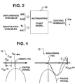
- Figure 2 shows certain input variables and certain output variables associated with operation of engine 10 in accordance with principles of the invention.
- the input variables are grouped into disturbance variables and manipulated variables.
- the output variables are control variables.
- the manipulated variables are engine fueling m f and intake valve closing IVC.
- the disturbance variables are intake manifold temperature and exhaust gas recirculation.
- the control variables are engine torque TQI and timing of auto-ignition ⁇ during the engine cycle.
- ECU 30 comprises algorithms for basic fuel and air management strategies for controlling the respective fuel management and air management systems.
- Fuel is managed by control of the quantity injected into a cylinder, and that quantity is controlled by controlling parameters relevant to operation of fuel injectors 22, such as injection pressure and injector open time.
- Air is managed by the time in the engine cycle at which the intake valve or valves of a cylinder are operated closed.
- parameter m f is a variable representing a target amount of fuel that should be injected into a cylinder during an engine cycle to form an air-fuel mixture
- parameter IVC is a variable representing the intake valve closing for that same cylinder.
- the manipulated variables change to cause the engine to operate in a way that delivers the proper torque for the load at the desired speed.
- charge air enters intake manifold 42 at a particular entrance location the actual amount of charge air entering a particular cylinder is likely to depend to some extent on how distant its intake valve or valves is or are from the charge air entrance location. The same is true for recirculated exhaust gases.
- the invention is premised upon modeling an actual engine to ascertain the relevant cylinder-to-cylinder and/or cycle-to-cycle variations.
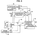
- the model 50 is depicted generally in Figure 2 . How that model is implemented in the engine control strategy is shown in Figure 3 .
- Model 50 is associated with an auto-ignition predictive controller 52. They comprise algorithms that are repeatedly executed by processing performed by ECU 30 and that collectively form a virtual controller that controls engine fueling and intake valve closing.
- Model 50 processes a particular set of values for certain input data useful in predicting the onset of auto-ignition and resulting torque during an engine cycle according to a predictor algorithm model.
- the particular input data comprises engine speed N, desired torque TQDES, exhaust gas recirculation EGR, and intake manifold temperature IMT.
- the processing develops a data value for predicted onset of auto-ignition ⁇ AI and a data value for resulting engine torque TQ AI .
- a further result of the processing develops a data value for control of the fuel management system and a data value for control of the air management system that will produce the predicted onset of auto-ignition and resulting torque.
- These two data values are IVC ff and M f ff .
- the data values for torque TQ AI and for ⁇ AI are inputs to respective algebraic summing functions 54, 56 that respectively calculate the difference between TQ AI and actual torque TQ being produced and the difference between ⁇ AI and the actual time at which auto-ignition occurs ⁇ AI .
- the differences are in effect error signals that are used in closed loop control of the fuel and air management systems.
- a control variable detector 58 resolves engine torque and crank angle at which auto-ignition occurs to provide TQ and ⁇ .
- Each pressure transducer 44 measures pressure in the corresponding cylinder 20 and the processing of pressure data may comprise integrating the pressure over the combustion cycle to calculate torque and using the instantaneous pressure rise to indicate start of auto- ignition.
- a virtual instrument comprising an analytical model (simplified thermodynamic and chemistry models based on initial temperature and mixture conditions may give optimum estimates) with the aide of a knock sensor can provide the information.
- the various references to "Plant” mean data about how the engine (plant) is operating, data that is obtained either from sensors, or that in some way is inferred from other data.
- the obtained or inferred data is data that is important to control of auto-ignition, such as the intake manifold temperature IMT and the EGR amount. That latter may be obtained by a variety of methods, such as through O 2 sampling in intake and exhaust, a hot-film anemometer, a Venturi-style meter, etc.
- Reference numeral 60 designates sources that provide data representing measured intake manifold temperature and the EGR amount. Those two data items are inputs to respective summing functions 62, 64.
- Disturbances to the variables IMT and EGR are collectively designated by system disturbance 66 in Figure 3 .
- Such disturbances are the result of cylinder-to-cylinder variations and/or cycle-to-cycle variations, as discussed earlier.
- Predictive controller 52 contains stores or maps defining the relationship between the target or desired values of torque and timing of auto-ignition to the manipulative variables, represented here as intake valve closing and fuel delivery. Additionally, the controller incorporates a correction algorithm based on a PID controller that is incorporated in the algorithm that implements closed loop duty-cycle control of both torque and auto-ignition timing.
- the algorithm introduces corrections to fueling and to valve timing to project changes in torque and auto-ignition timing as will be more fully explained with reference to Figures 4 , 5, and 6 .
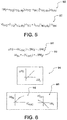
- a change in torque ⁇ TQ is related to a change in valve timing ⁇ IVC and to a change in fueling ⁇ M f according to the mathematical relationship 90 in Figure 6 . Because a change in valve timing influences torque significantly less than does a change in fueling, torque change ⁇ TQ may be considered roughly proportional to change in fueling ⁇ M f as portrayed by the graphical representation 94 in Figure 6 .
- a change in auto-ignition timing ⁇ AI is related to a change in valve timing ⁇ IVC and to a change in fueling ⁇ M f according to the mathematical relationship 92 in Figure 6 .
- the graphical representations 96, 98 in Figure 6 respectively show that a positive change in valve timing ⁇ IVC will cause a positive change in auto-ignition timing ⁇ AI but that a positive change in fueling ⁇ M f will cause a negative change in auto-ignition timing ⁇ AI .
- the PID control of air and fuel by controller 52 processes data values for torque error and auto-ignition timing error to develop respective corrections to the respective duty cycle control of fueling and intake valve timing.
- Figure 5 shows a mathematical relationship 80 that relates fueling correction to torque error and auto-ignition timing error.
- ⁇ TQ,dty represents a positive error in torque (insufficient torque being produced)
- ⁇ ⁇ AI,dty represents a positive error in auto-ignition timing (auto-ignition occurred too early).
- ⁇ TQ and ⁇ ⁇ AI are correlation factors that respectively correlate the respective error values (measured in terms of duty cycle) to fueling correction values.
- g TQ and g ⁇ AI are gain factors that provide for adjusting the relative contribution of each of the two terms when empirical testing of a particular engine model discloses that it is appropriate to favor the contribution of torque error over auto-ignition timing error, or vice versa, for a certain operating condition.
- a positive torque error means that more torque is needed and hence fueling needs to be increased. That is why the first term after the equal sign is positive. However, because a positive error in timing of auto-ignition means that auto-ignition occurred to early, fueling should be decreased to make the correction, and that is why the second term after the equal sign is negative.
- Figure 5 also shows a mathematical relationship 82 that relates intake valve timing correction to torque error and auto-ignition timing error.
- ⁇ TQ and ⁇ ⁇ AI are correlation factors that respectively correlate the respective error values (measured in terms of duty cycle) to timing correction values.
- h TQ and h ⁇ AI are gain factors that provide for adjusting the relative contribution of each of the two terms when empirical testing of a particular engine model discloses that it is appropriate to favor the contribution of torque error over auto-ignition timing error, or vice versa, for a certain operating condition.
- a positive torque error indicating more power is needed, calls for advancing timing of intake valve closing to make the correction, as reflected by the first term after the equal sign, which is positive.
- Negative torque error and negative auto-ignition timing error produce corrections in the opposite directions from corrections made as a consequence of positive torque error and positive auto-ignition error.
- a graph 70 in Figure 4 portrays the general effect of the controller strategy on auto-ignition timing.
- ⁇ o AI represent timing of auto-ignition before the strategy acts, such as would be measured by detector 58
- ⁇ AI des the desired timing, which is closer to engine top dead center (TDC), such as would be provided by model 50.
- the auto-ignition timing error is the difference, and in this instance positive.
- the strategy functions to adjust timing of intake valve closing and fueling in a way that seeks to null out the error, and while auto-ignition timing tends to converge toward the desired, or target, timing, the error may not be completely nulled out. The extent to which error remains will depend to some extent on the particular engine operating conditions.
- a graph 72 in Figure 4 portrays the general effect of the controller strategy on timing of intake valve closing.
- ⁇ o represent timing of intake valve closing before the strategy acts, such as would be measured by in any suitably appropriate way.
- ⁇ represent the target time of intake valve closing, which earlier in the engine cycle.
- the timing error is the difference, and in this instance positive.
- the strategy functions to adjust timing of intake valve closing and fueling in a way that seeks to null out the error, and while timing of intake valve closing tends to converge toward the desired, or target, timing, the error may not be completely nulled out.
- the extent to which error remains will depend to some extent on the particular engine operating conditions. Collectively, timing of auto-ignition and of intake valve closing are controlled to deliver essentially an optimum solution for both, even when error remain.
- the resulting combustion temperatures are controlled in ways that avoid the higher temperatures that promote formation of NOx in tailpipe emissions.
- the present invention provides a control algorithm to make the process of auto-ignition more robust.
- Varying intake valve closing on a cylinder-by-cylinder basis varies effective compression ratio on a cylinder-by-cylinder basis. If a particular cylinder has been mapped during engine development (either by modeling or actual experiment) to establish how actual intake manifold temperature may depart from the global value for IMT used as an input to predictor 50 (such global value being obtained for example from a temperature sensor at a particular location), such departures are used to adjust, or compensate, the data value for global IMT in managing fueling and intake valve closing for the particular cylinder.
- the compensation amounts are added to the global values by the summing functions 62, 64, and the sums are used as inputs to controller 52.
- the global value is the input to controller 52.
Landscapes
- Engineering & Computer Science (AREA)
- Chemical & Material Sciences (AREA)
- Combustion & Propulsion (AREA)
- Mechanical Engineering (AREA)
- General Engineering & Computer Science (AREA)
- Electrical Control Of Air Or Fuel Supplied To Internal-Combustion Engine (AREA)
- Output Control And Ontrol Of Special Type Engine (AREA)
- Combined Controls Of Internal Combustion Engines (AREA)
Description
- This invention relates to diesel engines that at times operate by alternative diesel combustion (ADC) processes, such as HCCI, CAI, DCCS, or HPCS, to cause auto-ignition of an air-fuel mixture as the mixture is being compressed in an engine cylinder.
- HCCI (homogeneous charge compression ignition) is a recognized process for fueling a diesel engine in a manner that creates a substantially homogeneous air-fuel charge inside an engine cylinder during a compression upstroke of an engine cycle. After a desired quantity of fuel for the charge has been injected into the cylinder to create a generally homogeneous air-fuel mixture, the increasing compression of the charge by the upstroking piston creates sufficiently large temperature to cause auto-ignition of the charge near or at top dead center (TDC). Auto-ignition may occur as the substantially simultaneous spontaneous combustion of vaporized fuel at various locations within the mixture.
- One of the attributes of HCCI is that relatively lean, or dilute, mixtures can be combusted, keeping the combustion temperatures relatively low. By avoiding the creation of relatively higher combustion temperatures, HCCI can yield significant reductions in the generation of NOX, an undesired constituent of engine exhaust gas.
- Another attribute of HCCI is that auto-ignition of a substantially homogeneous air-fuel charge generates more complete combustion and consequently relatively less soot in engine exhaust.
- The potential benefit of HCCI on reducing tailpipe emissions is therefore rather significant, and consequently HCCI is a subject of active investigation and development by many scientists and engineers in the engine research and design community.
- HCCI may be considered one of several alternative combustion processes for a compression ignition engine. Other processes that may be considered alternative combustion processes include Controlled Auto-Ignition (CAI), Dilution Controlled Combustion Systems (DCCS), and Highly Premixed Combustion Systems (HPCS).
- By whatever name an alternative combustion system or process may be called, a common attribute is that fuel is injected into a cylinder well before TDC to form an air-fuel charge that is increasingly compressed until auto-ignition occurs near or at top dead center (TDC).
- If such alternative processes are not suitable over the full range of engine operation for any particular engine, the engine may be fueled in the traditional conventional diesel manner where charge air is compressed to the point where it causes the immediate ignition of fuel upon fuel being injected into a cylinder, typically very near or at top dead center where compression is a maximum.
- With the availability of processor-controlled fuel injection systems capable of controlling fuel injection with precision that allows fuel to be injected at different injection pressures, at different times, and for different durations during an engine cycle over the full range of engine operation, a diesel engine becomes capable of operating by alternative combustion processes and/or traditional diesel combustion. The advent of variable valve actuation systems allows timing of engine valves to be processor-controlled in various ways, and with precision.
- The
WO 03/016698 A1 - The
DE 102 37 328 A1 discloses a regulation method for a combustion process of a HCCI-combustion engine. During the controlled auto-ignition operation, a modelled combustion process is formed with the help of regulated values influencing the combustion process. Output quantities of the model combustion process are used for the regulation of the regulated values influencing the process. The model combustion process is corrected by a comparison between the output quantities of the actual combustion process and the modelled combustion process. - The
US 2004/0103860 A1 discloses a premixed charge compression ignition engine, and a control system which effectively initiates combustion by compression ignition and maintains stable combustion while achieving extremely low nitrous oxide emissions, good overall efficiency and exceptable combustion noise and cylinder pressures. The present engine and control sytem effectively controls the combustion history that is the time at which combustion occurs, the weight of combustion, the duration of combustion and/or the completeness of combustion, by controlling the operation of certain control variables providing temperature control, pressure control, control of the mixtures auto-ignition properties and equivalence ratio control. The combustion control system provides active feedback control of the combustion event and includes a sensor, e.g. pressure sensor, for detecting an engine operation condition indicative of the combustion history, e.g. the start of combustion, and generating an associated engine operation condition signal. A processor receives the signal and generates control signals based on the engine operating condition signal for controlling various engine components to control the temperature, pressure, equivalence ratio and/or auto-ignition properties so as to variably control the combustion history of future combustion events to achieve stable, low emission combustion in each cylinder and combustion balancing between the cylinders. - As will be explained by later description, the present invention takes advantage of the capabilities of such processor-controlled fuel and valve actuation systems to better control auto-ignition when a compression ignition engine is operating in an alternative diesel combustion mode.
- Because a diesel engine that powers a motor vehicle runs at different speeds and loads depending on various inputs to both the vehicle and the engine that influence engine operation, fueling requirements change as speed and load change. An associated processing system processes data indicative of parameters such as engine speed and engine load to develop control data for setting desired engine fueling for particular operating conditions. A control algorithm seeks to secure fuel injection system operation that will provide the desired fueling at each of various combinations of engine speed and engine load.
- A variable valve actuation system can also be controlled in different ways according to different engine speed-load conditions to provide effective compression ratio appropriate to each of multiple combinations of those conditions. A control algorithm seeks to secure a desired effective compression ratio that in conjunction with fueling determined by the fuel control algorithm will cause auto-ignition of an in-cylinder mixture to occur at a desired time in the engine cycle that creates desired torque at the particular engine speed.
- Even with good control of both fueling and cylinder valve timing, disturbances that create cylinder-to-cylinder variations and/or cycle-to-cycle variations in auto-ignition and resulting torque may be present in an engine. Too early auto-ignition can cause certain undesired effects like potentially damaging engine knock. Too late auto-ignition can result in power loss. These disturbances may be inherent in the design of a particular engine, typically because each cylinder is at a different location in the engine and may therefore operate at a small but nonetheless significant temperature difference from other cylinders and/or may at a different distance from the point at which charge air enters the intake manifold than other cylinders.
- Management of both air and fuel are important in achieving auto-ignition at a desired time during the engine cycle when a diesel engine is operating by an alternative combustion process. The availability of processor-controlled variable valve actuation systems can operate engine valves in ways for managing airflow into the cylinders to achieve a desired quantity of charge air in the mixture compressed in each cylinder. Likewise, the quantity of fuel in the mixture can be well controlled by processor-controlled fuel systems. As engine operating conditions change, fuel and air can be varied in ways appropriate for changing conditions.
- HCCI, DCCS, HPCS, and other alternative internal combustion processes have disclosed, both theoretically and experimentally, the possibility of significant reductions in engine-out emission level, including NOx and soot. One of the factors that can be used effectively for accomplishing these reductions is effective compression ratio. It is believed that an industry-accepted definition for effective compression ratio is the ratio of in-cylinder pressure at the end of a compression stroke to the in-cylinder pressure at the end of an effective intake stroke. Controlling the amount of charge air that is allowed to enter a cylinder will control the effective compression ratio.
- The present invention employs variable valve actuation and fuel control strategies for achieving air-fuel mixtures that will auto-ignite at the proper time in the engine cycle to provide the desired torque at the speed at which the engine is running.
- These variations include intake manifold temperature and exhaust gas recirculation.
- The invention seeks to control certain variables (control variables) so as to minimize variations in characteristics of auto-ignition (e.g., variations in time of auto-ignition from cycle-to-cycle in a particular cylinder or variations from cylinder-to-cylinder) that tend to occur when fuel is introduced into a cylinder relatively early in a compression upstroke and auto-ignition is delayed significantly so as to allow the fuel and charge air to better mix before auto-ignition actually occurs.
- Certain variables (disturbance variables and manipulated variables) affect auto-ignition. One variable that affects auto-ignition is temperature of the air-fuel mixture that is being compressed. Proper control of that temperature can avoid premature auto-ignition that could cause severe knock and lead to engine damage. Certain prior attempts to control mixture temperature have been directed toward (a) optimization of piston geometry to enhance mixture homogeneity, (b) limiting effective compression ratio (in the case of Diesel or high cetene fuels lowering compression ratio is desired since these fuels ignite easily as compared to gasoline fuels) to limit in-cylinder temperature rise, (c) optimization of fuel injection strategy (e.g., sequence and relative contributions of multiple injections), (d) optimization of the amount of exhaust gas recirculation (EGR) and EGR temperature, and (e) optimization of the valve timing sequence.
- The present invention provides a control strategy that compensates control variables in a manner that attenuates the influence of multiple sources of noise (disturbance variables) that affect the auto-ignition process. Whereas previous techniques have employed certain hardware additions or modifications in efforts to minimize the influence of noise, the present invention embodies a model-based approach that guards against engine misfire caused by typical disturbances found in an engine. By containing misfire, the invention provides a robust auto-ignition process.
- Disturbances can arise in various ways such as from uneven cooling of various cylinders, variations in air-charge at each cylinder owing to non-identical airflow patterns through the intake system to the individual cylinders, uneven firing order, and unequal distribution of EGR gases. The inventive strategy provides control over each cylinder injector and a variable valve timing mechanism where the valve timing may be adjusted at each cylinder. The disclosed embodiment described here controls individual cylinder fueling and intake valve closing as manipulative variables, while accounting for the presence of disturbances like those mentioned as disturbance variables, to yield values for control of air and fuel management systems that will cause auto-ignition at the proper time in the engine cycle to produce desired torque.
- It is believed that the invention not only can reduce engine-out emissions, but also can contribute to improvements in other aspects of engine performance in a motor vehicle. Moreover, the invention can be embodied in a cost-effective manner in production vehicles that already have electronic engine control systems and variable valve actuation systems because it is embodied in the control strategy.
Various mechanisms that are disclosed in various patents and technical literature may be used to change effective compression ratio of an engine. Examples are described in commonly ownedU.S. Patent Nos. 6,044,815 and6,263,842 . They comprise hydraulically-assisted engine valve actuators that can change individual valves and control individual cylinders for better combustion control and that are useful in compensating for different charge temperatures resulting from different cylinder locations in an engine. - The present invention relates to an engine and method for enhancing the use of alternative combustion processes in a diesel engine toward objectives that include further reducing the generation of undesired constituents in engine exhaust, especially soot and NOX. The invention is embodied in air and fuel management strategies. The air management strategy uses variable valve actuation to control intake valve closing. The strategies are implemented by suitable programming in an associated processing system of an engine control system.
One generic aspect of the present invention relates to a method of operating a compression ignition engine according to claim 4. The engine has a processor-based engine control system controlling both a fueling system for fueling the engine and a variable valve actuation system that controls operation of intake valves that open and close an intake system to individual engine cylinders.
The method comprises processing certain data to develop both fueling data for fueling an engine cylinder and intake valve operating data for operating an intake valve for the cylinder. The intake valve operating data is developed by execution of an algorithm in the control system that controls ECR of the cylinder for causing commencement of auto-ignition of fuel in the cylinder to occur during a compression stroke in advance of top dead center at an in-cylinder temperature within a defined temperature range. The cylinder is fueled according to the fueling data.
The variable valve actuation system is controlled according to the intake valve operating data to allow air to pass from the intake system through the intake valve into the cylinder in an amount that causes commencement of auto-ignition of fuel in the cylinder to occur during the compression stroke in advance of top dead center at an in-cylinder temperature within the defined temperature range. - A further generic aspect relates to a multi-cylinder diesel engine according to independent claim 1. The engine comprises
cylinders within which combustion occurs to run the engine, a fueling system for fueling the cylinders, an intake system for introducing charge air into the cylinders, including a variable valve actuation system that controls operation of intake valves that open and close the intake system to individual engine cylinders, and a processor-based engine control system controlling both the fueling system and the variable valve actuation system.
The processing portion of the control system processes certain data to develop fueling data for fueling the engine cylinders and intake valve operating data for operating the cylinder intake valves.
The intake valve operating data is developed by execution of an algorithm in the control system that controls ECR of the cylinders for causing commencement of auto-ignition of fuel in the cylinders to occur during compression strokes in advance of top dead center at in-cylinder temperatures within a defined temperature range. - A more specific aspect of both the method and engine is that the intake valves begin to open at or near the beginning of an intake stroke immediately preceding the compression stroke and close before the conclusion of the intake stroke. The closing occurs sufficiently before the conclusion of the intake stroke to allow expansion of in-cylinder air during the remainder of the intake stroke sufficient to create some decrease in in-cylinder temperature.
- The foregoing, along with further features and advantages of the invention, will be seen in the following disclosure of a presently preferred embodiment of the invention depicting the best mode contemplated at this time for carrying out the invention. This specification includes drawings, now briefly described as follows.
-
-
Figure 1 is a schematic diagram of an engine and associated devices relevant to principles of the invention. -
Figure 2 is a general diagram showing certain input variables and certain output variables associated with operation of the engine ofFigure 1 in accordance with the invention. -
Figure 3 is a schematic diagram illustrating a detailed implementation of the inventive principles in the engine ofFigure 1 . -
Figure 4 comprises two graph plots useful in understanding the inventive principles. -
Figure 5 comprises two equations related to the implementation of the inventive principles. -
Figure 6 comprises additional equations and graph plots involving the inventive principles. -
Figure 1 shows portions of an exemplary internal combustion engine 10 that embodies principles of the present invention. Engine 10 comprises anintake system 12 through which charge air for combustion enters the engine and anexhaust system 14 through which exhaust gases resulting from combustion exit the engine. Engine 10 operates on the principle of compression ignition, and is turbocharged by aturbocharger 16 that has aturbine 16T inexhaust system 14 and acompressor 16C inintake system 12. When used as the prime mover of a motor vehicle, such as a truck, engine 10 is coupled through adrivetrain 18 to driven wheels that propel the vehicle. - Engine 10 comprises multiple cylinders 20 (either in an in-line configuration or a V-configuration) forming combustion chambers into which fuel is injected by
fuel injectors 22 as elements of afuel management system 23 to mix with charge air that has entered throughintake system 12. Pistons that reciprocate withincylinders 20 are coupled to an engine crankshaft. - An air-fuel mixture in each
cylinder 20 combusts under pressure created by the corresponding piston as the engine cycle passes from its compression phase to its power phase, thereby driving the engine crankshaft, which in turn delivers torque throughdrivetrain 18 to the wheels that propel the vehicle. Gases resulting from combustion are exhausted throughexhaust system 14. - Engine 10 has intake valves 24 and
exhaust valves 26 associated withcylinders 20. A variable··valve actuation mechanism 28 is part of an air management system that opens and closes at least the intake valves and may also open and close the exhaust valves. Each cylinder has at least one intake valve and at least one exhaust valve. - Engine 10 also comprises an engine control unit (E∼D) 30 that comprises one or more processors that process various data to develop data for controlling various aspects of engine operation.
ECD 30 acts via appropriate interfaces with bothfuel system 23 and variablevalve actuation system 28 to control the timing and amount of fuel injected by each fuel injector and at least the closing of the intake valves. - A representative variable valve actuation system includes devices that allow the basic valve operating profile to be adjusted for each particular cylinder to compensate for cylinder-to-cylinder variations in certain variables, such as temperature, due to the particular location of a cylinder in an engine. A paper by C. Vafidis, "The Application of an Electro-Hydraulic VVA System on a Passenger Car C.R. Diesel Engine", (ATA 20A2011), describes such a system. The paper was presented at the ATA (Associacioni Tecnica De Automobile) Congress on The Future of Diesel Engine Technology for Passenger Cars, Porto Cervo, Italy, 12-13 October 2000.
- Controlling both the quantity of fuel injected into a cylinder and the quantity of charge air allowed into the cylinder during an engine cycle for the cylinder controls the proportions of air and fuel in the resulting air-fuel mixture. The quantity of diesel fuel injected into a cylinder is determined by calculations performed by
ECD 30 processing data relevant to such a determination, and resulting fuel injector operation that will cause the calculated quantity to be injected. The quantity of charge air allowed into a cylinder is determined by calculations performed byECU 30 processing data relevant to such a determination, and resulting closing of the intake valve or valves of the cylinder at a proper time during the compression upstroke. - The creation of the air-fuel mixture occurs early enough to allow the fuel to mix with air before any ignition occurs. The increasing pressure imparted to the mixture eventually results in its auto-ignition near or at engine top dead center (TDC). By proper control of the proportions of fuel and air to run the engine at a desired speed and torque, auto-ignition occurs at the proper time to produce the desired operation of the engine.
- For controlling tailpipe emissions, engine 10 operates to recirculate a controlled quantity of exhaust gas through an
EGR loop 32 inexhaust system 14.EGR loop 32 has an inlet for engine exhaust coming fromengine exhaust manifold 38, anEGR cooler 34 for cooling the hot exhaust gases, and anEGR valve 36 that when open passes the cooled exhaust gases to an outlet opening tointake system 12. The extent to which exhaust gases can flow throughloop 32 is set by howfar valve 36 is allowed to open, and that is under the control ofECU 30, which processes data useful in determining the value of a parameter EGRP that sets the amount of valve opening. Hence withvalve 36 open, some quantity of exhaust gas is added to the air-fuel mixture in a cylinder by entraining with charge air passing from anintercooler 40 inintake system 12 to anengine intake manifold 42. - A
respective pressure transducer 44 is associated with eachcylinder 20 to measure in-cylinder pressure and furnish a corresponding data signal toECU 30. -
Figure 2 shows certain input variables and certain output variables associated with operation of engine 10 in accordance with principles of the invention. The input variables are grouped into disturbance variables and manipulated variables. The output variables are control variables. - The manipulated variables are engine fueling mf and intake valve closing IVC. The disturbance variables are intake manifold temperature and exhaust gas recirculation. The control variables are engine torque TQI and timing of auto-ignition θ during the engine cycle.
-
ECU 30 comprises algorithms for basic fuel and air management strategies for controlling the respective fuel management and air management systems. Fuel is managed by control of the quantity injected into a cylinder, and that quantity is controlled by controlling parameters relevant to operation offuel injectors 22, such as injection pressure and injector open time. Air is managed by the time in the engine cycle at which the intake valve or valves of a cylinder are operated closed. Hence parameter mf is a variable representing a target amount of fuel that should be injected into a cylinder during an engine cycle to form an air-fuel mixture, and parameter IVC is a variable representing the intake valve closing for that same cylinder. As engine speed and load change, the manipulated variables change to cause the engine to operate in a way that delivers the proper torque for the load at the desired speed. Those knowledgeable in engine control strategies will understand that various other factors, not specifically discussed here, bear on the processing that determines the actual data values for engine fueling mf and intake valve closing IVC. - If variables that are associated with the cylinders were uniform from cylinder to cylinder, each cylinder would be charged with fuel and air in exactly the same way. In an actual engine, that is typically not the case. Cylinder-to-cylinder variations in variables like intake manifold temperature and EGR are likely to exist. The present invention takes those variations into account as disturbance variables.
- If charge air enters
intake manifold 42 at a particular entrance location, the actual amount of charge air entering a particular cylinder is likely to depend to some extent on how distant its intake valve or valves is or are from the charge air entrance location. The same is true for recirculated exhaust gases. The invention is premised upon modeling an actual engine to ascertain the relevant cylinder-to-cylinder and/or cycle-to-cycle variations. Themodel 50 is depicted generally inFigure 2 . How that model is implemented in the engine control strategy is shown inFigure 3 . -
Model 50 is associated with an auto-ignitionpredictive controller 52. They comprise algorithms that are repeatedly executed by processing performed byECU 30 and that collectively form a virtual controller that controls engine fueling and intake valve closing. -
Model 50 processes a particular set of values for certain input data useful in predicting the onset of auto-ignition and resulting torque during an engine cycle according to a predictor algorithm model. The particular input data comprises engine speed N, desired torque TQDES, exhaust gas recirculation EGR, and intake manifold temperature IMT. The processing develops a data value for predicted onset of auto-ignition θAI and a data value for resulting engine torque TQAI. - A further result of the processing develops a data value for control of the fuel management system and a data value for control of the air management system that will produce the predicted onset of auto-ignition and resulting torque. These two data values are IVCff and Mf ff.
- The data values for torque TQAI and for θAI are inputs to respective algebraic summing
functions - A
control variable detector 58 resolves engine torque and crank angle at which auto-ignition occurs to provide TQ and θ. Eachpressure transducer 44 measures pressure in thecorresponding cylinder 20 and the processing of pressure data may comprise integrating the pressure over the combustion cycle to calculate torque and using the instantaneous pressure rise to indicate start of auto- ignition. Alternatively, a virtual instrument comprising an analytical model (simplified thermodynamic and chemistry models based on initial temperature and mixture conditions may give optimum estimates) with the aide of a knock sensor can provide the information. - In
Figure 3 , the various references to "Plant" mean data about how the engine (plant) is operating, data that is obtained either from sensors, or that in some way is inferred from other data. The obtained or inferred data is data that is important to control of auto-ignition, such as the intake manifold temperature IMT and the EGR amount. That latter may be obtained by a variety of methods, such as through O2 sampling in intake and exhaust, a hot-film anemometer, a Venturi-style meter, etc.Reference numeral 60 designates sources that provide data representing measured intake manifold temperature and the EGR amount. Those two data items are inputs to respective summingfunctions - Disturbances to the variables IMT and EGR are collectively designated by
system disturbance 66 inFigure 3 . Such disturbances are the result of cylinder-to-cylinder variations and/or cycle-to-cycle variations, as discussed earlier. -
Predictive controller 52 contains stores or maps defining the relationship between the target or desired values of torque and timing of auto-ignition to the manipulative variables, represented here as intake valve closing and fuel delivery. Additionally, the controller incorporates a correction algorithm based on a PID controller that is incorporated in the algorithm that implements closed loop duty-cycle control of both torque and auto-ignition timing. - The algorithm introduces corrections to fueling and to valve timing to project changes in torque and auto-ignition timing as will be more fully explained with reference to
Figures 4 ,5, and 6 . - A change in torque ΔTQ is related to a change in valve timing δζIVC and to a change in fueling δMf according to the
mathematical relationship 90 inFigure 6 . Because a change in valve timing influences torque significantly less than does a change in fueling, torque change ΔTQ may be considered roughly proportional to change in fueling δMf as portrayed by thegraphical representation 94 inFigure 6 . - A change in auto-ignition timing ΔθAI is related to a change in valve timing δζIVC and to a change in fueling δMf according to the
mathematical relationship 92 inFigure 6 . Thegraphical representations Figure 6 respectively show that a positive change in valve timing δζIVC will cause a positive change in auto-ignition timing ΔθAI but that a positive change in fueling δMf will cause a negative change in auto-ignition timing ΔθAI. - These relationships, which have been developed by the inventor from empirical correlations gathered from engine testing, set forth the basis for the inventor's strategy of simultaneous management of both fuel and air to optimize alternative diesel combustion. With these functional relationships embodied in the controller, fueling and intake valve closing are continually duty-cycle-controlled to increase or decrease the contributions to torque and auto-ignition timing to minimize the error in these two control variables with respect to their desired values.
- The PID control of air and fuel by
controller 52 processes data values for torque error and auto-ignition timing error to develop respective corrections to the respective duty cycle control of fueling and intake valve timing. -
Figure 5 shows amathematical relationship 80 that relates fueling correction to torque error and auto-ignition timing error. εTQ,dty represents a positive error in torque (insufficient torque being produced), and εθAI,dty represents a positive error in auto-ignition timing (auto-ignition occurred too early). αTQ and αθAI are correlation factors that respectively correlate the respective error values (measured in terms of duty cycle) to fueling correction values. gTQ and gθAI are gain factors that provide for adjusting the relative contribution of each of the two terms when empirical testing of a particular engine model discloses that it is appropriate to favor the contribution of torque error over auto-ignition timing error, or vice versa, for a certain operating condition. A positive torque error means that more torque is needed and hence fueling needs to be increased. That is why the first term after the equal sign is positive. However, because a positive error in timing of auto-ignition means that auto-ignition occurred to early, fueling should be decreased to make the correction, and that is why the second term after the equal sign is negative. -
Figure 5 also shows amathematical relationship 82 that relates intake valve timing correction to torque error and auto-ignition timing error. βTQ and βθAI are correlation factors that respectively correlate the respective error values (measured in terms of duty cycle) to timing correction values. hTQ and hθAI are gain factors that provide for adjusting the relative contribution of each of the two terms when empirical testing of a particular engine model discloses that it is appropriate to favor the contribution of torque error over auto-ignition timing error, or vice versa, for a certain operating condition. A positive torque error, indicating more power is needed, calls for advancing timing of intake valve closing to make the correction, as reflected by the first term after the equal sign, which is positive. This occurs in conjunction with an increase in fueling by virtue of the fueling correction component based on torque. A positive error in auto-ignition timing, meaning that auto-ignition occurred too early, also calls for advancing timing of intake valve closing to make the correction, as reflected by the second term after the equal sign, which is also positive. This occurs in conjunction with a decrease in fueling by virtue of the fueling correction component based on auto-ignition timing, and the collective effect produces correction in the proper direction because effective compression ratio, and consequently in-cylinder temperature, are both lowered. - Negative torque error and negative auto-ignition timing error produce corrections in the opposite directions from corrections made as a consequence of positive torque error and positive auto-ignition error.
- A
graph 70 inFigure 4 portrays the general effect of the controller strategy on auto-ignition timing. Let θo AI represent timing of auto-ignition before the strategy acts, such as would be measured bydetector 58, and θAI,des the desired timing, which is closer to engine top dead center (TDC), such as would be provided bymodel 50. The auto-ignition timing error is the difference, and in this instance positive. As the strategy begins to act, timing of auto-ignition approaches the desired timing. The strategy functions to adjust timing of intake valve closing and fueling in a way that seeks to null out the error, and while auto-ignition timing tends to converge toward the desired, or target, timing, the error may not be completely nulled out. The extent to which error remains will depend to some extent on the particular engine operating conditions. - A
graph 72 inFigure 4 portrays the general effect of the controller strategy on timing of intake valve closing. Let ζo represent timing of intake valve closing before the strategy acts, such as would be measured by in any suitably appropriate way. Let ζ represent the target time of intake valve closing, which earlier in the engine cycle. The timing error is the difference, and in this instance positive. As the strategy begins to act, timing of intake valve closing approaches the desired time. The strategy functions to adjust timing of intake valve closing and fueling in a way that seeks to null out the error, and while timing of intake valve closing tends to converge toward the desired, or target, timing, the error may not be completely nulled out. The extent to which error remains will depend to some extent on the particular engine operating conditions. Collectively, timing of auto-ignition and of intake valve closing are controlled to deliver essentially an optimum solution for both, even when error remain. - By enabling auto-ignition at the desired time in the engine cycle, the resulting combustion temperatures are controlled in ways that avoid the higher temperatures that promote formation of NOx in tailpipe emissions. The present invention provides a control algorithm to make the process of auto-ignition more robust.
- Varying intake valve closing on a cylinder-by-cylinder basis varies effective compression ratio on a cylinder-by-cylinder basis. If a particular cylinder has been mapped during engine development (either by modeling or actual experiment) to establish how actual intake manifold temperature may depart from the global value for IMT used as an input to predictor 50 (such global value being obtained for example from a temperature sensor at a particular location), such departures are used to adjust, or compensate, the data value for global IMT in managing fueling and intake valve closing for the particular cylinder. Likewise, if a particular cylinder has been mapped during engine development (either by modeling or actual experiment) to establish how actual EGR may depart from the global value for EGR used as an input to
predictor 50, such departures are used to compensate the data value for global EGR in managing fueling and intake valve closing for the particular cylinder. - Hence, the compensation amounts are added to the global values by the summing
functions controller 52. In the absence of any compensation amount the global value is the input tocontroller 52. - While a presently preferred embodiment of the invention has been illustrated and described, it should be appreciated that principles of the invention apply to all embodiments falling within the scope of the following claims.
Claims (6)
- A multi-cylinder diesel engine (10) that at times is operable by an alternative diesel combustion (ADC) process that causes diesel fuel to be injected into a cylinder in advance of engine top dead center (TDC) and mix with charge air and some amount of recirculated exhaust gas (EGR) to form an air-fuel mixture that is compressed to auto-ignition as the cycle approaches top dead center (TDC), the engine (10) comprising:a fuel management system (23) for controlling fuel in an air-fuel mixture created in a cylinder (20) during an engine cycle;an air management system (12) for controlling charge air in each air-fuel mixture during an engine cycle;a processor-based engine control system (30) controlling both the fuel management system (23) and the air management system (12) via a virtual controller for managing fueling and intake valve closing (IVC) for a particular cylinder thatA) processes a particular set of values for certain input data (N, TQDES, EGR, IMT) comprising data representing engine speed (N), data representing desired engine torque (TGDES), data representing global engine intake manifold temperature (IMT) data and data representing global recirculated exhaust gas (EGR) data for developing according to a predictor algorithm model (50) a data value for predicted time (ΘAI) of auto-ignition and a data value for resulting engine torque (TQAI), and for developing according to a predictor algorithm model (50) a data value (Mf ff) for control of the fuel management system and a data value (IVCff) for control of the air management system that will produce the predicted time (ΘAI) of auto-ignition and resulting torque (TQAI) based on the particular set of values for the certain input data (N, TQDES, EGR, IMT), and thatB) feeds forward to a control algorithm (52) and processes the data values for predicted time (ΘAI) of auto-ignition and for resulting engine torque (TQAI) developed by the predictor algorithm (50) and data values for the global engine intake manifold temperature (IMT) and the global recirculated exhaust gas (EGR) according to the control algorithm (52) that compensates the respective data values (IVCff, Mf ff) for control of the respective management systems for any disturbance in intake manifold temperature (δIMT) and for any disturbance in recirculated exhaust gas (δEGR) being processed by the control algorithm (52) by summing the disturbance in intake manifold temperature (δIMT) and the global engine intake manifold temperature (IMT) by a first summing function (62) and by summing the disturbance in recirculated exhaust gas (δEGR) and the global recirculated exhaust gas (EGR) by a second summing function (64) as input data for the control algorithm (52) and consequently causes the respective management systems to be controlled by respective compensated a first data value for intake valve closing (IVC) and a second data value for fueling (Mf) that produce the predicted time (ΘAI) of auto-ignition and resulting torque (TQAI) in the presence of any such disturbance,wherein a correction (δMf) for fueling (Mf) is provided by the following mathematical equation:
 wherein a correction (δζIVC) for intake valve closing (IVC) is provided by the following mathematical equation:
 wherein the air management system comprises a variable valve timing system (28) for controlling the timing of operation of intake valves (24) at the cylinders (20), and the data value for the air management system (12) to control charge air in the created mixture controls timing of intake valve closing.
 - An engine (10) as set forth in Claim 1 wherein the engine control system (30) controls air-fuel mixture in each of multiple cylinders (20) via the virtual controller developing respective compensated data values (IVC), (Mf) for control of air-fuel mixture in each cylinder that produce the predicted time (ΘAI) of auto- ignition and resulting torque (TQAI) in the presence of different disturbances (δIMT) in intake manifold temperature affecting the cylinders (20) as determined by a predefined relationship of intake manifold temperature (IMT) at each individual cylinder (20) to the global intake manifold temperature (IMT) data and in the presence of different disturbances (δEGR) in recirculated exhaust gas affecting the cylinders as determined by a predefined relationship of recirculated exhaust gas (EGR) in each individual cylinder (20) with the global recirculated exhaust gas (EGR) data.
- An engine (10) as set forth in Claim 1 including a source of feedback (58) for providing a data value for actual time (θ) of auto-ignition in a cylinder and a data value for actual resulting torque (TQI), which data values are processed with the data value for predicted time (ΘAI) of auto-ignition and the data value for resulting engine torque (TQAI) based on the particular set of values for the certain input data by the control algorithm, to develop respective error data values that are processed by the control algorithm in closed loop control of the respective management systems.
- A method of operating a multi-cylinder diesel engine (10) that at times is operable by an alternative diesel combustion (ADC) process that causes diesel fuel to be injected into a cylinder in advance of engine top dead center (TDC) and mix with charge air and some amount of recirculated exhaust gas (EGR) to form an air-fuel mixture that is compressed to auto-ignition as the cycle approaches top dead center (TDC), the method comprising:controlling, for managing fueling and intake valve closing (IVC) for a particular cylinder, the quantity of fuel that a fuel management system (23) injects and the quantity of charge air that an air management system (12) allows into an engine cylinder (20) during an engine cycle to create an air-fuel mixture byA) processing a particular set of values for certain input data (N, TQDES, EGR, IMT) comprising data representing engine speed (N), data representing desired engine torque (TGDES), data representing global engine intake manifold temperature (IMT) data and data representing global recirculated exhaust gas (EGR) data by developing according to an predictor algorithm model in a virtual controller in a processing system a data value for predicted time (ΘAI) of auto-ignition and a data value for resulting engine torque (TQAI), and developing according to a predictor algorithm model (50) a data value (Mf ff) for control of the fuel management system and a data value (IVCff) for control of the air management system that will produce the predicted time (ΘAI) of auto- ignition and resulting torque (TQAI) based on the particular set of values for the certain input data(N, TQDES, EGR, IMT), andB) feeds forward to a control algorithm (52) and processing the data values for predicted time (ΘAI) of auto-ignition and a data value for resulting engine torque (TQAI) developed by the predictor algorithm and data values for the global engine intake manifold temperature (IMT) and the global recirculated exhaust gas (EGR) according to a control algorithm in the virtual controller that compensates the respective data values (IVCff, Mf ff) for control of the respective management systems for any disturbance in intake manifold temperature (δIMT) and for any disturbance in recirculated exhaust gas (δEGR) being processed by the control algorithm (52) by summing the disturbance in intake manifold temperature (δIMT) and the global engine intake manifold temperature (IMT) by a first summing function (62) and by summing the disturbance in recirculated exhaust gas (δEGR) and the global recirculated exhaust gas (EGR) by a second summing function (64) as input data for the control algorithm (52), and consequentlyC) causing the respective management systems to be controlled by respective compensated data values (IVC, Mf) that cause auto-ignition to occur at the predicted time (ΘAI) and develop the resulting torque (TQAI) in the presence of any such disturbance (δIMT, δEGR),wherein a correction (δMf) for fueling (Mf) is provided by the following mathematical equation:
 wherein a correction (δζIVC) for intake valve closing (IVC) is provided by the following mathematical equation:
 the method further comprising controlling the air management system (12) by controlling the timing of operation of intake valves (24) at the cylinders (20) using the data value for the air management system (12) to control charge air in the created mixture to control timing of intake valve closing.
 - A method as set forth in Claim 4 comprising controlling air-fuel mixture in each of multiple cylinders (20) via the virtual controller developing respective compensated data values (IVC, Mf) for control of air-fuel mixture in each cylinder (20) that produce the predicted time (ΘAI) of auto-ignition and resulting torque (TQAI) in the presence of disturbances (δIMT) in intake manifold temperature affecting individual cylinders differently as determined by a predefined relationship of intake manifold temperature (IMT) at each individual cylinder (20) with the global intake manifold temperature (IMT) data and in the presence of disturbances (δEGR) in recirculated exhaust gas (EGR) affecting individual cylinders differently as determined by a predefined relationship of recirculated exhaust gas in each individual cylinder (20) with the global recirculated exhaust gas (EGR) data.
- A method as set forth in Claim 4 including processing the data value for predicted time (ΘAI) of auto-ignition, the data value for resulting engine torque (TQAI) based on the particular set of values for the certain input data, a data value for actual time (θ) of auto-ignition in a cylinder, and a data value for actual resulting torque (TQI) to develop respective error data values, and processing the error data values in closed loop control of the respective management systems.
Applications Claiming Priority (2)
| Application Number | Priority Date | Filing Date | Title |
|---|---|---|---|
| US11/238,379 US7184877B1 (en) | 2005-09-29 | 2005-09-29 | Model-based controller for auto-ignition optimization in a diesel engine |
| PCT/US2006/034940 WO2007040904A1 (en) | 2005-09-29 | 2006-09-07 | Model-based controller for auto-ignition optimization in a diesel engine |
Publications (3)
| Publication Number | Publication Date |
|---|---|
| EP1943421A1 EP1943421A1 (en) | 2008-07-16 |
| EP1943421A4 EP1943421A4 (en) | 2010-02-10 |
| EP1943421B1 true EP1943421B1 (en) | 2020-03-11 |
Family
ID=37769717
Family Applications (1)
| Application Number | Title | Priority Date | Filing Date |
|---|---|---|---|
| EP06803157.4A Active EP1943421B1 (en) | 2005-09-29 | 2006-09-07 | Model-based controller for auto-ignition optimization in a diesel engine |
Country Status (8)
| Country | Link |
|---|---|
| US (1) | US7184877B1 (en) |
| EP (1) | EP1943421B1 (en) |
| JP (1) | JP5113757B2 (en) |
| KR (1) | KR20080063778A (en) |
| CN (1) | CN101278116B (en) |
| BR (1) | BRPI0616778A2 (en) |
| CA (1) | CA2623381C (en) |
| WO (1) | WO2007040904A1 (en) |
Families Citing this family (21)
| Publication number | Priority date | Publication date | Assignee | Title |
|---|---|---|---|---|
| EP1706616A1 (en) * | 2004-01-14 | 2006-10-04 | Lotus Cars Limited | A turbocharged internal combustion engine |
| EP1808592A4 (en) * | 2004-11-02 | 2009-09-16 | Honda Motor Co Ltd | Plant and internal combustion engine control device |
| US7730870B2 (en) * | 2006-12-08 | 2010-06-08 | Ford Global Technologies, Llc | Engine dynamic load leveling |
| US8150576B2 (en) * | 2007-06-25 | 2012-04-03 | International Engine Intellectual Property Company Llc | Engine glow plug diagnosis using crankshaft sensor data |
| KR101197476B1 (en) | 2008-07-02 | 2012-11-09 | 주식회사 만도 | Solenoid valve for brake system |
| US8266890B2 (en) * | 2009-06-10 | 2012-09-18 | International Engine Intellectual Property Company, Llc | Preventing soot underestimation in diesel particulate filters by determining the restriction sensitivity of soot |
| US20110025045A1 (en) * | 2009-07-29 | 2011-02-03 | International Engine Intellectual Property Company, Llc | Fitting with audible misassembly indicator |
| US8146542B2 (en) | 2009-07-29 | 2012-04-03 | International Engine Intellectual Property Company Llc | Adaptive EGR cooling system |
| US20110036315A1 (en) * | 2009-08-12 | 2011-02-17 | International Engine Intellectual Property Company Llc | Valve lift control apparatus |
| US8010276B2 (en) | 2009-08-31 | 2011-08-30 | International Engine Intellectual Property Company, Llc | Intake manifold oxygen control |
| US8306710B2 (en) | 2010-04-14 | 2012-11-06 | International Engine Intellectual Property Company, Llc | Method for diesel particulate filter regeneration in a vehicle equipped with a hybrid engine background of the invention |
| EP2466098B1 (en) * | 2010-12-17 | 2013-09-25 | Perkins Engines Company Limited | An Internal Combustion Engine and a Method of Operation of an Internal Combustion Engine |
| US9429096B2 (en) | 2011-09-15 | 2016-08-30 | Robert Bosch Gmbh | Predictive modeling and reducing cyclic variability in autoignition engines |
| US9702298B2 (en) * | 2014-12-09 | 2017-07-11 | Ford Global Technologies, Llc | Diagnostic method for a compressor recirculation valve |
| US9556810B2 (en) * | 2014-12-31 | 2017-01-31 | General Electric Company | System and method for regulating exhaust gas recirculation in an engine |
| CN107269408B (en) * | 2017-05-15 | 2022-08-05 | 吉林大学 | Diesel engine optimized combustion controller and simulation model control method |
| DE102017005783B4 (en) * | 2017-06-20 | 2021-12-02 | Mtu Friedrichshafen Gmbh | Method for model-based control and regulation of an internal combustion engine |
| EP3680477B1 (en) * | 2017-09-06 | 2025-11-26 | IHI Corporation | Engine control system |
| CN113374589B (en) * | 2021-06-09 | 2022-09-20 | 同济大学 | A fully variable valve-based adaptive intake control method and storage medium |
| CA3256354A1 (en) * | 2022-05-25 | 2023-11-30 | Cespira Canada Limited Partnership | Apparatus and method for managing autoignition in an in-cylinder injector and combustion chamber of an internal combustion engine |
| CN116816523B (en) * | 2023-07-10 | 2025-11-25 | 浙江吉利控股集团有限公司 | Methods, devices, vehicles, and storage media for determining engine intake air temperature |
Family Cites Families (20)
| Publication number | Priority date | Publication date | Assignee | Title |
|---|---|---|---|---|
| CN1065586C (en) * | 1994-12-30 | 2001-05-09 | 本田技研工业株式会社 | Fuel injection control device for IC engine |
| US6230683B1 (en) * | 1997-08-22 | 2001-05-15 | Cummins Engine Company, Inc. | Premixed charge compression ignition engine with optimal combustion control |
| US6286482B1 (en) | 1996-08-23 | 2001-09-11 | Cummins Engine Company, Inc. | Premixed charge compression ignition engine with optimal combustion control |
| DE19805299A1 (en) | 1998-02-10 | 1999-08-12 | Deutz Ag | Electronic control device |
| JP3500951B2 (en) * | 1998-03-09 | 2004-02-23 | 株式会社日立製作所 | Non-throttle compression-ignition internal combustion engine and control method thereof |
| JPH11257162A (en) * | 1998-03-13 | 1999-09-21 | Isuzu Motors Ltd | EGR device for multi-cylinder engine |
| US6263842B1 (en) | 1998-09-09 | 2001-07-24 | International Truck And Engine Corporation | Hydraulically-assisted engine valve actuator |
| US6044815A (en) | 1998-09-09 | 2000-04-04 | Navistar International Transportation Corp. | Hydraulically-assisted engine valve actuator |
| JP3817977B2 (en) * | 1999-07-06 | 2006-09-06 | 株式会社日立製作所 | Control method of compression ignition engine |
| DE10009180C2 (en) * | 2000-02-26 | 2002-04-25 | Daimler Chrysler Ag | Process for producing a homogeneous mixture for self-igniting internal combustion engines and for controlling the combustion process |
| JP4075312B2 (en) * | 2001-01-26 | 2008-04-16 | いすゞ自動車株式会社 | Engine combustion control method and apparatus |
| US6953024B2 (en) * | 2001-08-17 | 2005-10-11 | Tiax Llc | Method of controlling combustion in a homogeneous charge compression ignition engine |
| AT5646U1 (en) * | 2001-08-27 | 2002-09-25 | Avl List Gmbh | METHOD FOR OPERATING AN INTERNAL COMBUSTION ENGINE |
| JP2003232233A (en) | 2001-12-06 | 2003-08-22 | Nissan Motor Co Ltd | Control device for internal combustion engine |
| DE10237328B4 (en) | 2002-08-14 | 2006-05-24 | Siemens Ag | Method for controlling the combustion process of an HCCI internal combustion engine |
| JP4161789B2 (en) * | 2003-04-25 | 2008-10-08 | いすゞ自動車株式会社 | Fuel injection control device |
| JP4254355B2 (en) * | 2003-06-09 | 2009-04-15 | トヨタ自動車株式会社 | Ignition timing control method for premixed compression ignition combustion internal combustion engine |
| JP4206882B2 (en) * | 2003-09-24 | 2009-01-14 | いすゞ自動車株式会社 | Premixed compression self-ignition internal combustion engine |
| US6971365B1 (en) * | 2004-07-12 | 2005-12-06 | General Motors Corporation | Auto-ignition gasoline engine combustion chamber and method |
| US6994072B2 (en) * | 2004-07-12 | 2006-02-07 | General Motors Corporation | Method for mid load operation of auto-ignition combustion |
-
2005
- 2005-09-29 US US11/238,379 patent/US7184877B1/en not_active Expired - Lifetime
-
2006
- 2006-09-07 BR BRPI0616778-0A patent/BRPI0616778A2/en not_active Application Discontinuation
- 2006-09-07 KR KR1020087009699A patent/KR20080063778A/en not_active Abandoned
- 2006-09-07 CA CA2623381A patent/CA2623381C/en not_active Expired - Fee Related
- 2006-09-07 EP EP06803157.4A patent/EP1943421B1/en active Active
- 2006-09-07 JP JP2008533385A patent/JP5113757B2/en not_active Expired - Fee Related
- 2006-09-07 WO PCT/US2006/034940 patent/WO2007040904A1/en not_active Ceased
- 2006-09-07 CN CN2006800364637A patent/CN101278116B/en not_active Expired - Fee Related
Non-Patent Citations (1)
| Title |
|---|
| None * |
Also Published As
| Publication number | Publication date |
|---|---|
| KR20080063778A (en) | 2008-07-07 |
| EP1943421A4 (en) | 2010-02-10 |
| CN101278116A (en) | 2008-10-01 |
| BRPI0616778A2 (en) | 2011-06-28 |
| CA2623381C (en) | 2012-01-24 |
| JP5113757B2 (en) | 2013-01-09 |
| JP2009510326A (en) | 2009-03-12 |
| CA2623381A1 (en) | 2007-04-12 |
| WO2007040904A1 (en) | 2007-04-12 |
| EP1943421A1 (en) | 2008-07-16 |
| CN101278116B (en) | 2010-07-14 |
| US7184877B1 (en) | 2007-02-27 |
Similar Documents
| Publication | Publication Date | Title |
|---|---|---|
| US7184877B1 (en) | Model-based controller for auto-ignition optimization in a diesel engine | |
| CN102235257B (en) | The method that multiple injection timing controls | |
| US9297319B2 (en) | Control of EGR, fresh mass air flow, and boost pressure for internal combustion engines | |
| US8640679B2 (en) | Method of model-based multivariable control of EGR and boost for internal combustion engines | |
| US8370065B2 (en) | Engine control system with algorithm for actuator control | |
| JP4525729B2 (en) | EGR distribution variation detection device | |
| CN102797569B (en) | Engine transient operation period is to the self adaptive control utilizing rare NOx trap of biodiesel to regenerate | |
| US9777657B2 (en) | On-line adaptive PID control of air charging system | |
| US9885297B2 (en) | Energy balance based boost control using feedback linearization | |
| US20100116249A1 (en) | Engine control system and method | |
| US9719437B2 (en) | Engine control systems and methods for achieving a torque value | |
| US8649955B2 (en) | Engine control system with algorithm for actuator control | |
| JP2009103062A (en) | Intake amount correction device | |
| US20110106408A1 (en) | Engine control system with algorithm for actuator control | |
| US7574299B2 (en) | Fuel injection control apparatus and method for internal combustion engine | |
| EP2757238B1 (en) | Control device for an internal combustion engine | |
| US8463530B2 (en) | Method for operating auto ignition combustion engine | |
| US9151203B2 (en) | Humidity corrections for fuel setpoint adaptation | |
| US20130247883A1 (en) | Control device for internal combustion engine | |
| EP2778377B1 (en) | Control device of internal combustion engine | |
| US8843298B2 (en) | Engine control system for actuator control | |
| EP3069001B1 (en) | Control device for internal combustion engine | |
| JP5817342B2 (en) | Control target value setting method for internal combustion engine and control device for internal combustion engine |
Legal Events
| Date | Code | Title | Description |
|---|---|---|---|
| PUAI | Public reference made under article 153(3) epc to a published international application that has entered the european phase |
Free format text: ORIGINAL CODE: 0009012 |
|
| 17P | Request for examination filed |
Effective date: 20080429 |
|
| AK | Designated contracting states |
Kind code of ref document: A1 Designated state(s): AT DE FR GB IT SE |
|
| DAX | Request for extension of the european patent (deleted) | ||
| RBV | Designated contracting states (corrected) |
Designated state(s): AT DE FR GB IT SE |
|
| A4 | Supplementary search report drawn up and despatched |
Effective date: 20100112 |
|
| 17Q | First examination report despatched |
Effective date: 20100507 |
|
| STAA | Information on the status of an ep patent application or granted ep patent |
Free format text: STATUS: EXAMINATION IS IN PROGRESS |
|
| GRAP | Despatch of communication of intention to grant a patent |
Free format text: ORIGINAL CODE: EPIDOSNIGR1 |
|
| STAA | Information on the status of an ep patent application or granted ep patent |
Free format text: STATUS: GRANT OF PATENT IS INTENDED |
|
| INTG | Intention to grant announced |
Effective date: 20190920 |
|
| GRAS | Grant fee paid |
Free format text: ORIGINAL CODE: EPIDOSNIGR3 |
|
| GRAA | (expected) grant |
Free format text: ORIGINAL CODE: 0009210 |
|
| STAA | Information on the status of an ep patent application or granted ep patent |
Free format text: STATUS: THE PATENT HAS BEEN GRANTED |
|
| AK | Designated contracting states |
Kind code of ref document: B1 Designated state(s): AT DE FR GB IT SE |
|
| REG | Reference to a national code |
Ref country code: GB Ref legal event code: FG4D |
|
| REG | Reference to a national code |
Ref country code: AT Ref legal event code: REF Ref document number: 1243414 Country of ref document: AT Kind code of ref document: T Effective date: 20200315 |
|
| REG | Reference to a national code |
Ref country code: DE Ref legal event code: R096 Ref document number: 602006059207 Country of ref document: DE |
|
| REG | Reference to a national code |
Ref country code: SE Ref legal event code: TRGR |
|
| REG | Reference to a national code |
Ref country code: AT Ref legal event code: MK05 Ref document number: 1243414 Country of ref document: AT Kind code of ref document: T Effective date: 20200311 |
|
| REG | Reference to a national code |
Ref country code: DE Ref legal event code: R097 Ref document number: 602006059207 Country of ref document: DE |
|
| PLBE | No opposition filed within time limit |
Free format text: ORIGINAL CODE: 0009261 |
|
| STAA | Information on the status of an ep patent application or granted ep patent |
Free format text: STATUS: NO OPPOSITION FILED WITHIN TIME LIMIT |
|
| PG25 | Lapsed in a contracting state [announced via postgrant information from national office to epo] |
Ref country code: AT Free format text: LAPSE BECAUSE OF FAILURE TO SUBMIT A TRANSLATION OF THE DESCRIPTION OR TO PAY THE FEE WITHIN THE PRESCRIBED TIME-LIMIT Effective date: 20200311 Ref country code: IT Free format text: LAPSE BECAUSE OF FAILURE TO SUBMIT A TRANSLATION OF THE DESCRIPTION OR TO PAY THE FEE WITHIN THE PRESCRIBED TIME-LIMIT Effective date: 20200311 |
|
| 26N | No opposition filed |
Effective date: 20201214 |
|
| GBPC | Gb: european patent ceased through non-payment of renewal fee |
Effective date: 20200907 |
|
| PG25 | Lapsed in a contracting state [announced via postgrant information from national office to epo] |
Ref country code: FR Free format text: LAPSE BECAUSE OF NON-PAYMENT OF DUE FEES Effective date: 20200930 |
|
| PG25 | Lapsed in a contracting state [announced via postgrant information from national office to epo] |
Ref country code: GB Free format text: LAPSE BECAUSE OF NON-PAYMENT OF DUE FEES Effective date: 20200907 |
|
| PGFP | Annual fee paid to national office [announced via postgrant information from national office to epo] |
Ref country code: DE Payment date: 20250820 Year of fee payment: 20 |
|
| PGFP | Annual fee paid to national office [announced via postgrant information from national office to epo] |
Ref country code: SE Payment date: 20250820 Year of fee payment: 20 |