EP1942669A1 - Electronic device - Google Patents
Electronic device Download PDFInfo
- Publication number
- EP1942669A1 EP1942669A1 EP07000221A EP07000221A EP1942669A1 EP 1942669 A1 EP1942669 A1 EP 1942669A1 EP 07000221 A EP07000221 A EP 07000221A EP 07000221 A EP07000221 A EP 07000221A EP 1942669 A1 EP1942669 A1 EP 1942669A1
- Authority
- EP
- European Patent Office
- Prior art keywords
- elastic
- elastic band
- cabinet
- speaker enclosure
- electronic device
- Prior art date
- Legal status (The legal status is an assumption and is not a legal conclusion. Google has not performed a legal analysis and makes no representation as to the accuracy of the status listed.)
- Withdrawn
Links
Images

Classifications
-
- H—ELECTRICITY
- H04—ELECTRIC COMMUNICATION TECHNIQUE
- H04N—PICTORIAL COMMUNICATION, e.g. TELEVISION
- H04N5/00—Details of television systems
- H04N5/64—Constructional details of receivers, e.g. cabinets or dust covers
- H04N5/642—Disposition of sound reproducers
-
- H—ELECTRICITY
- H04—ELECTRIC COMMUNICATION TECHNIQUE
- H04R—LOUDSPEAKERS, MICROPHONES, GRAMOPHONE PICK-UPS OR LIKE ACOUSTIC ELECTROMECHANICAL TRANSDUCERS; ELECTRIC HEARING AIDS; PUBLIC ADDRESS SYSTEMS
- H04R1/00—Details of transducers, loudspeakers or microphones
- H04R1/02—Casings; Cabinets ; Supports therefor; Mountings therein
- H04R1/025—Arrangements for fixing loudspeaker transducers, e.g. in a box, furniture
Definitions
- the present invention is related to an electronic device, such as a television set, according to the preamble of claim 1.
- Electronic devices with at least one speaker enclosure are used for TV sets, TV apparatuses or portable TV apparatuses and for computer assemblies.
- the television receiver comprises a cabinet and a speaker enclosure, mentioned as a speaker.
- connection means comprise a speaker positioning part, used to position the speaker, and a plurality of projection parts in the vicinity of the speaker positioning part on the cabinet.
- the elastic means are generated by at least one fixation band, which has holes at both ends and which is hooked to the projection parts of the connection means. The fixation band fixes the speaker by pressing it from behind and against the cabinet.
- the Patent Abstract of Japan JP08116582A describes a fixing structure for a speaker, which presses the speaker unit to a side wall by an additional elastic piece.
- the WO 9522015A describes vibration damping devices, which includes damping plates and which dissipate the vibration energy as heat.
- connection means mentioned as a speaker fixer, are known by the Patent Abstract of Japan JP2003-153127A .
- the speaker fixer has a holding part with an elastic member, used to tightly cover either one part of the speaker, or the entire speaker except for the sound discharge part. By deforming the elastic member the speaker is freely attached to and detached from the holding part.
- the elastic member needs a lot of space to cover the speaker.
- the elastic member, which covers the speaker generates an acoustic cavity with standing waves. As a result, this cavity could vibrate by air born transmission and transfer vibrations to the cabinet. Such a cavity also reduces the acoustic performance.
- An electronic device of the invention such as a television set, comprises a cabinet and at least one speaker enclosure which is connected to the cabinet by connection means and by elastic means.
- the speaker enclosure is floatingly suspended by the elastic means, which suspend the speaker enclosure and which are connected to the cabinet by the connection means.
- the elastic means comprise one or more elastic elements, which are connected to the speaker enclosure at one of their parts and which are connected to connection means with other parts in a way that the weight of the speaker enclosure is carried by the elastic elements and elastically transferred to the connection means.
- the speaker enclosure is suspended by the elastic means and floats in the cabinet.
- a speaker enclosure which is floatingly suspended by the elastic means, does not transfer any vibration to the cabinet. A transmission of vibrations from the speaker enclosure is completely prevented.
- the elastic means can comprise at least one elastic band, which can surround with at least an essential portion the speaker enclosure and which can be connected to the connection means. At the same time the elastic band can be tightened by the connection means. As a result, the speaker enclosure is suspended by the elastic band to the connection means and floats in the cabinet.
- a single elastic band can be provided, which suspends the speaker enclosure by surrounding it and which is tightened and connected to the cabinet by the connection means.
- the elastic means can comprise an inner elastic band, which suspends the speaker enclosure by surrounding it, and an outer elastic band, which is connected to the inner elastic band and which is tightened and connected to the cabinet by the connection means.
- connection means can comprise tension elements, which tighten the elastic means and which project from the cabinet. They can be generated by projection pins.
- connection means can comprise supporting elements for the elastic means, such as spacers guiding an elastic band, which are arranged on or to the tension elements. The supporting elements can provide a fixation of the elastic means to the connection means without interfering with the floating of the speaker enclosure.
- the single elastic band or the outer elastic band can comprise at least one guiding element and the connection means can comprise at least one tracking element, which project from the wall and corresponds to the guiding element.
- a guiding element can be generated by a loop of the corresponding elastic band and a tracking element can be generated by a projection bar. Guiding and tracking elements secure the speaker enclosure during the transport.
- the elastic means such as the elastic bands
- the elastic means such as the outer elastic band or both of the inner and outer elastic bands, can be generated as one piece by injection moulding of an elastomer.
- the speaker enclosure can comprise a circumferential groove, which guides the surrounding elastic band.
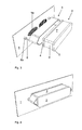
- An electronic device of a first embodiment of the invention such as a television set, comprises a cabinet 1 and at least one speaker enclosure 2, which is connected to the cabinet 1 by connection means and by elastic means.
- the speaker enclosure is floatingly suspended by one single elastic band 3 of the elastic means.
- the speaker enclosure 2 is shaped as a longish cuboid. It has a front cover 4 and a back cover 5, which are rectangular shaped, and four side covers 6 between the both. Two elliptical speaker openings 2a are arranged side by side along the long side of the front cover 4. The front cover 4 and the back cover 5 project the side covers 6 and, as a result, generate a circumferential groove 7 of the speaker enclosure 2.
- the cabinet 1 comprises openings 1a corresponding to the openings 2a of the speaker enclosure 2.
- the elastic band 3 is generated as an endless band, of which width corresponds to the width of the groove 7, i.e. in this embodiment to the distance between the front cover 4 and the back cover 5.
- the elastic band 3 surrounds the speaker enclosure 2 and is guided in the groove 7.
- the length of the elastic band 3 is longer than the circumference of the groove 7 in order to tighten the elastic band 3 by the connection means at a certain distance of the speaker enclosure 2.
- the elastic band 3 is tightened by tension elements of the connection elements, which are generated as two projection pins 8 projecting from the cabinet 1.
- the projection pins 8 are arranged vis-à-vis at the broadsides of the speaker enclosure 2 and between the speaker enclosure 2 and the elastic band 3.
- the projection pins 8 are provided with spacers 8a at its ends on the cabinet 1 in order to secure a certain distance between the cabinet 1 and the elastic band 3 with the speaker enclosure 2. The distance is greater than the thickness of the front cover 4.
- the distance between the two projection pins 8 is slightly longer than the longitudinal side of the speaker enclosure 2. In reference to the elastic band 3, this distance is so long that the elastic band 3, which surrounds the speaker enclosure 2, is tightened. At the same time the elastic band 3 is connected to the cabinet 1 by the projection pins 8.
- the elastic band 3 is made by an elastic soft rubber belt. It is generated as one piece by an injection moulding of an elastomer.
- the elastic band 3, fitted to the speaker enclosure 2, has two parallel surfaces 9, which expend along the longer sides of the speaker enclosure 2, and two angled surfaces 10, which are arranged vis-à-vis in the region of the protection pins 8.
- the parallel surfaces 9 pass into the angled surfaces 10 by edges 11.
- Each angled surface 10 comprises two sides connected by an edge 12, in which the corresponding projection pin 8 is arranged. This is best seen in figure 1 .
- the angle between the sides of the angled surfaces 10 can be between 120 and 60°, e.g. 90°.
- the elastic band 3 is tightened and the speaker enclosure 2 is floatingly suspended in the cabinet 1.
- the openings 2a of the speaker enclosure 2 are arranged in front of the corresponding openings 1a of the cabinet 1.
- the groove 7 of the speaker enclosure 2 can be generated by the side covers 6 itself.
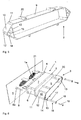
- An electronic device of a second embodiment of the invention corresponds in all ways to an electronic device of a first embodiment, except for the following features:
- the single elastic band 3 comprises stabilisation elements 13, 14, 15, which are generated by additional sections of the elastic band 3.
- one stabilisation element 13 In the region of each angled surface 10 one stabilisation element 13 generates an inner surface, which is arranged rectangular to the two parallel surfaces 9 and connects the both. This inner surface is guided in the groove 7 of the speaker enclosure 2 as well.
- Another stabilisation element 14 generates a cylindrical surface in the edge 12 and surrounds the corresponding projection pin 8.
- a third stabilisation element 15 generates a surface, which is parallel to the surfaces 9 and connects both of the other stabilisation elements 14, 13, i.e. the cylindrical surface with the inner surface at its middle.
- the connection means comprise supporting elements, which are generated as two supporting spacers 16.
- the supporting sleeves 16 are arranged to the tension elements, namely over the projection pins 8. In particular, they are arranged between the projection pins 8 and the stabilisation elements 14 generating the cylindrical surfaces.
- Each supporting sleeve 16 has a circumferential groove 17, which is generated by two collars 18 at both ends and which guides the elastic band 3, in particular the cylindrical surface of the stabilisation element 14.
- the connection means also comprise two screws 19 for fixing the supporting sleeves 16 on the projections pins 8, which are provided with corresponding threads. This is best seen in figures 5 and 6 .
- the single elastic band 3 comprises four guiding elements 20 and the connection means comprise four tracking elements 21, which project from the cabinet 1 and correspond to the guiding elements 20.
- Two of the guiding and tracking elements 20, 21 are arranged at the outer sides, at each of the parallel surfaces 9 of the elastic band 3.
- the guiding elements 20 are generated by sections of the elastic band 3, e.g. by a loop of the elastic band 3.
- the guiding elements 20 generate cylindrical surfaces.
- the tracking elements 21 are generated by U-shaped projection bars, in which the guiding elements 20 are guided. This is best seen in figure 7 .
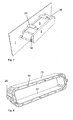
- An electronic device of a third embodiment of the invention corresponds in all ways to an electronic device of a first embodiment, except for the following features:
- the elastic means comprise an inner elastic band 22 and an outer elastic band 23.
- the inner elastic band 22 suspends the speaker enclosure 2 by surrounding it completely.
- the inner elastic band 22, which has a rectangular shape corresponding to the speaker enclosure 2, is guided in the groove 7 of the speaker enclosure 2.
- the outer elastic band 23, which is connected to the inner elastic band 22, is tightened and connected to the cabinet 1 by the connection means.
- the outer elastic band 23 surrounds the inner elastic band 22 at a certain constant distance. It is connected to the inner elastic band by elastic elements 24, which are generated by elastic band sections and which extend as an incline in reference to both elastic bands 22, 23. Sixteen of such elastic elements 24 are provided between the elastic bands 22, 23.
- one stabilisation element 25, which is generated by a band section is provided in the middle of each breadth outside of the outer elastic band 23. Both stabilisation elements 25, which correspond to the stabilisation elements 4, generate cylindrical surfaces. This is seen in figure 8 .
- Figure 8 does not show, that the stabilisation elements 25 surround the projection pins 8 and are guided in their grooves 17.
- the outer elastic band 23 is tightened and the inner elastic band 22, which is connected to the outer elastic band 23 by the elastic elements 24, carries the speaker enclosure 1. As a result, the speaker enclosure 2 is floatingly suspended.
Landscapes
- Engineering & Computer Science (AREA)
- Signal Processing (AREA)
- Physics & Mathematics (AREA)
- Acoustics & Sound (AREA)
- Multimedia (AREA)
- Details Of Audible-Bandwidth Transducers (AREA)
Abstract
Description
- The present invention is related to an electronic device, such as a television set, according to the preamble of
claim 1. Electronic devices with at least one speaker enclosure are used for TV sets, TV apparatuses or portable TV apparatuses and for computer assemblies. - An electronic device used for a television receiver is described by the Patent Abstract of Japan
JP2003-134421A - The Patent Abstract of Japan
JP08116582A - By pressing the speaker against the cabinet a certain amount of speaker vibrations can still be transmitted to the cabinet.
- A solution for preventing a transmission of vibrations from the speaker enclosure to the cabinet, which provides buffering means between the speaker enclosure and the cabinet, is known by the Patent Abstract of Japan
JP2002-252892A - The
WO 9522015A - The solutions mentioned above need additional means, such as an elastic piece, buffering means and damping devices, in addition to the connection means.
- Connection means, mentioned as a speaker fixer, are known by the Patent Abstract of Japan
JP2003-153127A - It is therefore desirable to improve an electronic device, such as a television set, according to the preamble of
claim 1, with respect to the connection of its at least one speaker enclosure to its cabinet. A transmission of vibrations from the speaker enclosure should be completely prevented. - According to the invention this can be achieved by the features of
claim 1. - An electronic device of the invention, such as a television set, comprises a cabinet and at least one speaker enclosure which is connected to the cabinet by connection means and by elastic means. According to the invention the speaker enclosure is floatingly suspended by the elastic means, which suspend the speaker enclosure and which are connected to the cabinet by the connection means. The elastic means comprise one or more elastic elements, which are connected to the speaker enclosure at one of their parts and which are connected to connection means with other parts in a way that the weight of the speaker enclosure is carried by the elastic elements and elastically transferred to the connection means. As a result, the speaker enclosure is suspended by the elastic means and floats in the cabinet.
- A speaker enclosure, which is floatingly suspended by the elastic means, does not transfer any vibration to the cabinet. A transmission of vibrations from the speaker enclosure is completely prevented.
- Possible advantageous developments of the invention are specified in the dependent claims.
- The elastic means can comprise at least one elastic band, which can surround with at least an essential portion the speaker enclosure and which can be connected to the connection means. At the same time the elastic band can be tightened by the connection means. As a result, the speaker enclosure is suspended by the elastic band to the connection means and floats in the cabinet.
- In one embodiment of the invention a single elastic band can be provided, which suspends the speaker enclosure by surrounding it and which is tightened and connected to the cabinet by the connection means.
- As an alternative, the elastic means can comprise an inner elastic band, which suspends the speaker enclosure by surrounding it, and an outer elastic band, which is connected to the inner elastic band and which is tightened and connected to the cabinet by the connection means.
- The connection means can comprise tension elements, which tighten the elastic means and which project from the cabinet. They can be generated by projection pins. In addition, the connection means can comprise supporting elements for the elastic means, such as spacers guiding an elastic band, which are arranged on or to the tension elements. The supporting elements can provide a fixation of the elastic means to the connection means without interfering with the floating of the speaker enclosure.
- The single elastic band or the outer elastic band can comprise at least one guiding element and the connection means can comprise at least one tracking element, which project from the wall and corresponds to the guiding element. A guiding element can be generated by a loop of the corresponding elastic band and a tracking element can be generated by a projection bar. Guiding and tracking elements secure the speaker enclosure during the transport.
- The elastic means, such as the elastic bands, can be made by elastic soft rubber belts. In particular, the elastic means, such as the outer elastic band or both of the inner and outer elastic bands, can be generated as one piece by injection moulding of an elastomer.
- The speaker enclosure can comprise a circumferential groove, which guides the surrounding elastic band.
- The invention will be explained in more detail using three embodiments, which are illustrated in
figures 1 to 8 . - It shows:
-
Figure 1 , a simplified perspective view of the single elastic band of the first embodiment of an electronic device; -
Figure 2 , a simplified perspective view of the speaker enclosure, which shows the front of the speaker enclosure; -
Figure 3 , a simplified exploded view of the cabinet, of the single elastic band and the speaker enclosure of the first embodiment; -
Figure 4 , a simplified perspective view of floatingly suspended speaker enclosure of the first embodiment; -
Figure 5 , a simplified perspective view of the single elastic band of the second embodiment of an electronic device; -
Figure 6 , a simplified exploded view of the cabinet, of the single elastic band and the speaker enclosure of the second embodiment; -
Figure 7 , a simplified perspective view of floatingly suspended speaker enclosure of the second embodiment; -
Figure 8 , a simplified perspective view of the single elastic band of the third embodiment of an electronic device. - An electronic device of a first embodiment of the invention, such as a television set, comprises a
cabinet 1 and at least onespeaker enclosure 2, which is connected to thecabinet 1 by connection means and by elastic means. - According to the invention the speaker enclosure is floatingly suspended by one single
elastic band 3 of the elastic means. - The
speaker enclosure 2 is shaped as a longish cuboid. It has afront cover 4 and aback cover 5, which are rectangular shaped, and four side covers 6 between the both. Twoelliptical speaker openings 2a are arranged side by side along the long side of thefront cover 4. Thefront cover 4 and theback cover 5 project the side covers 6 and, as a result, generate acircumferential groove 7 of thespeaker enclosure 2. Thecabinet 1 comprisesopenings 1a corresponding to theopenings 2a of thespeaker enclosure 2. - The
elastic band 3 is generated as an endless band, of which width corresponds to the width of thegroove 7, i.e. in this embodiment to the distance between thefront cover 4 and theback cover 5. Theelastic band 3 surrounds thespeaker enclosure 2 and is guided in thegroove 7. - The length of the
elastic band 3 is longer than the circumference of thegroove 7 in order to tighten theelastic band 3 by the connection means at a certain distance of thespeaker enclosure 2. - The
elastic band 3 is tightened by tension elements of the connection elements, which are generated as twoprojection pins 8 projecting from thecabinet 1. - The projection pins 8 are arranged vis-à-vis at the broadsides of the
speaker enclosure 2 and between thespeaker enclosure 2 and theelastic band 3. The projection pins 8 are provided withspacers 8a at its ends on thecabinet 1 in order to secure a certain distance between thecabinet 1 and theelastic band 3 with thespeaker enclosure 2. The distance is greater than the thickness of thefront cover 4. - The distance between the two
projection pins 8 is slightly longer than the longitudinal side of thespeaker enclosure 2. In reference to theelastic band 3, this distance is so long that theelastic band 3, which surrounds thespeaker enclosure 2, is tightened. At the same time theelastic band 3 is connected to thecabinet 1 by the projection pins 8. - The
elastic band 3 is made by an elastic soft rubber belt. It is generated as one piece by an injection moulding of an elastomer. - The
elastic band 3, fitted to thespeaker enclosure 2, has twoparallel surfaces 9, which expend along the longer sides of thespeaker enclosure 2, and twoangled surfaces 10, which are arranged vis-à-vis in the region of the protection pins 8. Theparallel surfaces 9 pass into theangled surfaces 10 byedges 11. Eachangled surface 10 comprises two sides connected by anedge 12, in which the correspondingprojection pin 8 is arranged. This is best seen infigure 1 . The angle between the sides of theangled surfaces 10 can be between 120 and 60°, e.g. 90°. - As a result, the
elastic band 3 is tightened and thespeaker enclosure 2 is floatingly suspended in thecabinet 1. Theopenings 2a of thespeaker enclosure 2 are arranged in front of thecorresponding openings 1a of thecabinet 1. - As an alternative, the
groove 7 of thespeaker enclosure 2 can be generated by the side covers 6 itself. - An electronic device of a second embodiment of the invention corresponds in all ways to an electronic device of a first embodiment, except for the following features:
- The single
elastic band 3 comprisesstabilisation elements elastic band 3. In the region of eachangled surface 10 onestabilisation element 13 generates an inner surface, which is arranged rectangular to the twoparallel surfaces 9 and connects the both. This inner surface is guided in thegroove 7 of thespeaker enclosure 2 as well. Anotherstabilisation element 14 generates a cylindrical surface in theedge 12 and surrounds the correspondingprojection pin 8. Athird stabilisation element 15 generates a surface, which is parallel to thesurfaces 9 and connects both of theother stabilisation elements - The connection means comprise supporting elements, which are generated as two supporting
spacers 16. The supportingsleeves 16 are arranged to the tension elements, namely over the projection pins 8. In particular, they are arranged between the projection pins 8 and thestabilisation elements 14 generating the cylindrical surfaces. Each supportingsleeve 16 has acircumferential groove 17, which is generated by twocollars 18 at both ends and which guides theelastic band 3, in particular the cylindrical surface of thestabilisation element 14. The connection means also comprise twoscrews 19 for fixing the supportingsleeves 16 on the projections pins 8, which are provided with corresponding threads. This is best seen infigures 5 and 6 . - The single
elastic band 3 comprises four guidingelements 20 and the connection means comprise fourtracking elements 21, which project from thecabinet 1 and correspond to the guidingelements 20. Two of the guiding and trackingelements parallel surfaces 9 of theelastic band 3. The guidingelements 20 are generated by sections of theelastic band 3, e.g. by a loop of theelastic band 3. The guidingelements 20 generate cylindrical surfaces. Thetracking elements 21 are generated by U-shaped projection bars, in which the guidingelements 20 are guided. This is best seen infigure 7 . - An electronic device of a third embodiment of the invention corresponds in all ways to an electronic device of a first embodiment, except for the following features:
- The elastic means comprise an inner
elastic band 22 and an outerelastic band 23. The innerelastic band 22 suspends thespeaker enclosure 2 by surrounding it completely. The innerelastic band 22, which has a rectangular shape corresponding to thespeaker enclosure 2, is guided in thegroove 7 of thespeaker enclosure 2. The outerelastic band 23, which is connected to the innerelastic band 22, is tightened and connected to thecabinet 1 by the connection means. The outerelastic band 23 surrounds the innerelastic band 22 at a certain constant distance. It is connected to the inner elastic band byelastic elements 24, which are generated by elastic band sections and which extend as an incline in reference to bothelastic bands elastic elements 24 are provided between theelastic bands stabilisation element 25, which is generated by a band section, is provided in the middle of each breadth outside of the outerelastic band 23. Bothstabilisation elements 25, which correspond to thestabilisation elements 4, generate cylindrical surfaces. This is seen infigure 8 . -
Figure 8 does not show, that thestabilisation elements 25 surround the projection pins 8 and are guided in theirgrooves 17. The outerelastic band 23 is tightened and the innerelastic band 22, which is connected to the outerelastic band 23 by theelastic elements 24, carries thespeaker enclosure 1. As a result, thespeaker enclosure 2 is floatingly suspended.
Claims (10)
- An electronic device, such as a television set, with a cabinet (1) and with at least one speaker enclosure (2) which is connected to the cabinet (1) by connection means and by elastic means characterized in that the speaker enclosure (1) is floatingly suspended by the elastic means, which suspends the speaker enclosure (2) and which are connected to the cabinet (1) by the connection means.
- The electronic device according to claim 1 characterized in that the elastic means comprise a single elastic band (3), which suspends the speaker enclosure (2) by surrounding it and which is tightened and connected with the cabinet (1) by the connection means.
- The electronic device according to claim 1 characterized in that the elastic means comprise an inner elastic band (22), which suspends the speaker enclosure (2) by surrounding it, and an outer elastic band (23), which is connected to the inner elastic band (22) and which is tightened and connected to the cabinet (1) by the connection means.
- The electronic device according to claim 3 characterized in that the outer elastic band (23) is connected to the inner elastic band (23) by elastic elements (24), which are generated by elastic band sections.
- The electronic device according to one of the claims 1 to 4 characterized in that the connection means comprise tension elements, which tighten the elastic means and which project from the cabinet (1).
- The electronic device according to claim 5 characterized in that the connection means comprise supporting elements, which are arranged to the tension elements.
- The electronic device according to one of the claims 2 to 6 characterized in that the single elastic band (3) or the outer elastic band (23) comprises at least one guiding element (20) and the connection means comprise at least one corresponding tracking element (21), which projects from the cabinet (1) and guides the guiding element (20).
- The electronic device according to one of the claims 2 to 7 characterized in that the elastic bands (3, 22, 23) are made by elastic soft rubber belts.
- The electronic device according to one of the claims 1 to 8 characterized in that the elastic means, such as the single elastic band (3) or both of the inner and outer elastic bands (22, 23) together, are generated as one piece by an injection moulding of an elastomer.
- The electronic device according to one of the claims 2 to 9 characterized in that the speaker enclosure (2) comprises a circumferential groove (7) guiding the surrounding elastic band (3, 22).
Priority Applications (1)
| Application Number | Priority Date | Filing Date | Title |
|---|---|---|---|
| EP07000221A EP1942669A1 (en) | 2007-01-08 | 2007-01-08 | Electronic device |
Applications Claiming Priority (1)
| Application Number | Priority Date | Filing Date | Title |
|---|---|---|---|
| EP07000221A EP1942669A1 (en) | 2007-01-08 | 2007-01-08 | Electronic device |
Publications (1)
| Publication Number | Publication Date |
|---|---|
| EP1942669A1 true EP1942669A1 (en) | 2008-07-09 |
Family
ID=38111336
Family Applications (1)
| Application Number | Title | Priority Date | Filing Date |
|---|---|---|---|
| EP07000221A Withdrawn EP1942669A1 (en) | 2007-01-08 | 2007-01-08 | Electronic device |
Country Status (1)
| Country | Link |
|---|---|
| EP (1) | EP1942669A1 (en) |
Cited By (4)
| Publication number | Priority date | Publication date | Assignee | Title |
|---|---|---|---|---|
| EP2262250A1 (en) * | 2009-06-05 | 2010-12-15 | Funai Electric Co., Ltd. | Flat panel display device |
| GB2474850A (en) * | 2009-10-27 | 2011-05-04 | Simon David Thomas | A music system support stand with rubber bands as supporting members |
| EP2770879A4 (en) * | 2011-10-26 | 2015-08-19 | Levoy Haight | SYSTEMS AND METHODS FOR MOVING A CINEMA SEAT |
| CN107817645A (en) * | 2017-12-11 | 2018-03-20 | 苏州佳世达光电有限公司 | Loudspeaker module and projector |
Citations (4)
| Publication number | Priority date | Publication date | Assignee | Title |
|---|---|---|---|---|
| GB852707A (en) * | 1957-07-31 | 1960-10-26 | Rokus Schelling | Improvements in cabinets for sound reproduction systems |
| US5115884A (en) * | 1989-10-04 | 1992-05-26 | James Falco | Low distortion audio speaker cabinet |
| US5681023A (en) * | 1995-12-07 | 1997-10-28 | Sheydayi; Alexei | Damping support member for audio reproduction components, particularly speaker enclosures |
| GB2399977A (en) * | 2003-03-19 | 2004-09-29 | Fujitsu Ten Ltd | Floating loudspeaker structure |
-
2007
- 2007-01-08 EP EP07000221A patent/EP1942669A1/en not_active Withdrawn
Patent Citations (4)
| Publication number | Priority date | Publication date | Assignee | Title |
|---|---|---|---|---|
| GB852707A (en) * | 1957-07-31 | 1960-10-26 | Rokus Schelling | Improvements in cabinets for sound reproduction systems |
| US5115884A (en) * | 1989-10-04 | 1992-05-26 | James Falco | Low distortion audio speaker cabinet |
| US5681023A (en) * | 1995-12-07 | 1997-10-28 | Sheydayi; Alexei | Damping support member for audio reproduction components, particularly speaker enclosures |
| GB2399977A (en) * | 2003-03-19 | 2004-09-29 | Fujitsu Ten Ltd | Floating loudspeaker structure |
Cited By (6)
| Publication number | Priority date | Publication date | Assignee | Title |
|---|---|---|---|---|
| EP2262250A1 (en) * | 2009-06-05 | 2010-12-15 | Funai Electric Co., Ltd. | Flat panel display device |
| US8295534B2 (en) | 2009-06-05 | 2012-10-23 | Funai Electric Co., Ltd. | Flat panel display device |
| GB2474850A (en) * | 2009-10-27 | 2011-05-04 | Simon David Thomas | A music system support stand with rubber bands as supporting members |
| EP2770879A4 (en) * | 2011-10-26 | 2015-08-19 | Levoy Haight | SYSTEMS AND METHODS FOR MOVING A CINEMA SEAT |
| CN107817645A (en) * | 2017-12-11 | 2018-03-20 | 苏州佳世达光电有限公司 | Loudspeaker module and projector |
| CN107817645B (en) * | 2017-12-11 | 2020-11-27 | 苏州佳世达光电有限公司 | Loudspeaker module and projector |
Similar Documents
| Publication | Publication Date | Title |
|---|---|---|
| US8369077B2 (en) | Mounting apparatus for data storage device | |
| US6751330B2 (en) | Speaker system | |
| KR100928482B1 (en) | LCD Display | |
| GB2347819A (en) | An arrangement for mounting a speaker on a display including vibration attenuation means. | |
| US9581662B2 (en) | Cylindrical magnetic resonance device having a circular arc shaped housing shell when mounted that becomes bar-shaped when demounted | |
| EP2579613A1 (en) | Array speaker system | |
| ATE528930T1 (en) | ELECTROACOUSTIC TRANSDUCER | |
| ES2031798T1 (en) | TENSION DEVICE OF A TENSION ROLLER FOR TRANSMISSION BY A FLEXIBLE BAND, THAT WORKS BY ELASTIC DEFORMATION OF A DEFORMABLE PARALLELEPIPEDIC SOLID. | |
| US20050074138A1 (en) | Feedback reducing receiver mount and assembly | |
| EP2856233B1 (en) | Cable port assemblies for telecommunications enclosure | |
| CN101828406B (en) | Recoil-free speaker system | |
| FR2797482B1 (en) | VIBRATION DAMPER DEVICE HAVING HIGH DURABILITY OF THE ELASTIC BODY | |
| US6279679B1 (en) | Selectively tuned vibration absorber | |
| DE602006017587D1 (en) | MODULAR MULTIPLE ELASTOMER BASIC VIBRATION / SHOCK ABSORPTION DEVICE | |
| TW201224293A (en) | Electronic device | |
| GB0123451D0 (en) | Device for reducing structural-acoustical coupling between the diaphragm vibration field and the enclosure acoustic modes | |
| US20150373437A1 (en) | Microphone fixing device | |
| US7035419B2 (en) | Anti-resonant structure for speakers | |
| CN101193453B (en) | Loudspeaker device | |
| KR100848017B1 (en) | Forced-air-cooled engine with cooling air guide cover | |
| TWM419196U (en) | Hard disk driver holding device | |
| US9583077B2 (en) | Electric stringed instrument amplifier | |
| WO2007011379A3 (en) | Improved field transportable high-power ultrasonic transducer assembly | |
| CN219875974U (en) | Sound box and shell thereof | |
| KR100710300B1 (en) | Speaker assembly of video display device |
Legal Events
| Date | Code | Title | Description |
|---|---|---|---|
| PUAI | Public reference made under article 153(3) epc to a published international application that has entered the european phase |
Free format text: ORIGINAL CODE: 0009012 |
|
| AK | Designated contracting states |
Kind code of ref document: A1 Designated state(s): AT BE BG CH CY CZ DE DK EE ES FI FR GB GR HU IE IS IT LI LT LU LV MC NL PL PT RO SE SI SK TR |
|
| AX | Request for extension of the european patent |
Extension state: AL BA HR MK RS |
|
| 17P | Request for examination filed |
Effective date: 20090109 |
|
| AKX | Designation fees paid |
Designated state(s): DE FR |
|
| GRAP | Despatch of communication of intention to grant a patent |
Free format text: ORIGINAL CODE: EPIDOSNIGR1 |
|
| RTI1 | Title (correction) |
Free format text: CABINET FOR AN ELECTRONIC DEVICE |
|
| RIN1 | Information on inventor provided before grant (corrected) |
Inventor name: ALLAIRE, CHRISTIAN Inventor name: EVENISSE, MICHEL Inventor name: SPERLE, CORNELIUS |
|
| STAA | Information on the status of an ep patent application or granted ep patent |
Free format text: STATUS: THE APPLICATION IS DEEMED TO BE WITHDRAWN |
|
| 18D | Application deemed to be withdrawn |
Effective date: 20110708 |