EP1942461A2 - Method and apparatus for reducing noise in an image using wavelet decomposition - Google Patents
Method and apparatus for reducing noise in an image using wavelet decomposition Download PDFInfo
- Publication number
- EP1942461A2 EP1942461A2 EP07016778A EP07016778A EP1942461A2 EP 1942461 A2 EP1942461 A2 EP 1942461A2 EP 07016778 A EP07016778 A EP 07016778A EP 07016778 A EP07016778 A EP 07016778A EP 1942461 A2 EP1942461 A2 EP 1942461A2
- Authority
- EP
- European Patent Office
- Prior art keywords
- image
- wavelet
- energy
- wavelet coefficients
- modifying
- Prior art date
- Legal status (The legal status is an assumption and is not a legal conclusion. Google has not performed a legal analysis and makes no representation as to the accuracy of the status listed.)
- Withdrawn
Links
Images






Classifications
-
- G—PHYSICS
- G06—COMPUTING OR CALCULATING; COUNTING
- G06T—IMAGE DATA PROCESSING OR GENERATION, IN GENERAL
- G06T5/00—Image enhancement or restoration
- G06T5/10—Image enhancement or restoration using non-spatial domain filtering
-
- G—PHYSICS
- G06—COMPUTING OR CALCULATING; COUNTING
- G06T—IMAGE DATA PROCESSING OR GENERATION, IN GENERAL
- G06T5/00—Image enhancement or restoration
- G06T5/70—Denoising; Smoothing
-
- G—PHYSICS
- G06—COMPUTING OR CALCULATING; COUNTING
- G06V—IMAGE OR VIDEO RECOGNITION OR UNDERSTANDING
- G06V10/00—Arrangements for image or video recognition or understanding
- G06V10/20—Image preprocessing
- G06V10/30—Noise filtering
-
- G—PHYSICS
- G06—COMPUTING OR CALCULATING; COUNTING
- G06T—IMAGE DATA PROCESSING OR GENERATION, IN GENERAL
- G06T2207/00—Indexing scheme for image analysis or image enhancement
- G06T2207/20—Special algorithmic details
- G06T2207/20016—Hierarchical, coarse-to-fine, multiscale or multiresolution image processing; Pyramid transform
-
- G—PHYSICS
- G06—COMPUTING OR CALCULATING; COUNTING
- G06T—IMAGE DATA PROCESSING OR GENERATION, IN GENERAL
- G06T2207/00—Indexing scheme for image analysis or image enhancement
- G06T2207/20—Special algorithmic details
- G06T2207/20048—Transform domain processing
- G06T2207/20064—Wavelet transform [DWT]
Definitions
- the present invention relates generally to image processing and in particular, to a method, apparatus and computer-readable medium embodying a computer program for reducing noise in an image using wavelet decomposition.
- Digital cameras have an ISO rating identifying their level of sensitivity to light. For most digital cameras, a default ISO 100 setting is normal although some digital cameras have default ISO settings as low as fifty (50).
- the PENGUIN ® digital camera board produced by Seiko Epson Corporation has an ISO range between fourteen (14) and nine-hundred and ten (910) and a default ISO 50 setting.
- SLR single-lens reflex
- the default ISO setting can be set to 200, 400, 800 or even 3200.
- Luminance noise gives images a grainy look when presented on an electronic display screen but is usually not visible when the images are printed. Chroma noise appears as random red and blue pixels and is typically less visible in images both on-screen and when printed. Chroma noise is most visible in smooth and/or dark areas of images and is more visible in red (R) and blue (B) channels. Chroma noise in the red and blue channels tends to contain more low and very low frequency components due to demosaicing and interpolation. Chroma noise also adversely affects color saturation and contrast.
- noise reduction methods such as for example, anistopic diffusion
- white noise has been added to images and compensate for image degradation on the basis of this assumption.
- noise in images captured by digital cameras having high ISO settings is not accurately modeled by this noise assumption and thus, these noise reducing methods have proven to be unsatisfactory.
- Wavelet methods for removing noise from images have gained in popularity.
- the Donoho-Johnstone method is a popular and efficient denoising method incorporating wavelets and makes use of soft or hard thresholds.
- the image is wavelet decomposed to generate wavelet coefficients representing the image detail. All of the wavelet coefficients below threshold levels are reduced to zero. Wavelet coefficients exceeding the threshold levels are either unmodified (hard) or reduced (soft).
- This method has proven to be most successful when the noise in the image generally conforms to expected Gaussian white noise.
- this method requires the arbitrary a priori selection of the threshold levels. As a result, depending on the selected threshold levels, if the noise is not white noise, detail in the image may be lost, an insufficient amount of noise may be removed from the image or the noise may be improperly removed from the image.
- noise reducing algorithms have been considered but these noise reducing algorithms are expensive in terms of processing time. Many of these methods, similar to the anistropic diffusion method referred to above, incorporate assumed noise models and thus, unsuccessfully address noise when the noise does not accurately fit within the noise models.
- U.S. Patent No. 6,163,619 to Maruo discloses a method in which an input digital image of an object is subjected to a Wavelet transform. An image energy quantity for a combined area of X-axis high pass information and Y-axis high pass information contained in the image data resulting from the Wavelet transform, is calculated. The object is deemed acceptable or faulty depending on whether the image energy quantity is below or above a given value.
- U.S. Patent No. 6,836,569 to Le Pennac et al. discloses a method and apparatus for processing an n-dimensional digitized signal using foveal processing, which constructs a sparse signal representation by taking advantage of the geometrical regularity of signal structures.
- Foveal coefficients are computed with one-dimensional inner products along trajectories of an n-directional trajectory list.
- a trajectory finder computes the n-directional trajectory list from the input n-dimensional signals, in order to choose optimal locations to compute the foveal coefficients.
- a foveal reconstruction processor recovers a signal approximation which has the same geometrical structures as the input signal along the trajectories and which is regular away from the trajectories.
- a foveal residue can be calculated as a difference with the input signal.
- a bandlet processor decorrelates the foveal coefficients by applying invertible linear operators along each trajectory. Bandlet coefficients are inner products between the signal and n-dimensional bandlet vectors elongated along the trajectories.
- a geometric processor computes geometric coefficients by decorrelating the coordinates of the trajectories with linear operators, to take advantage of their geometrical regularity. Setting small bandlet coefficients and small geometric coefficients to zero yields the sparse signal representation.
- U.S. Patent Application Publication No. 2003/0095206 to Wredenhagen et al. discloses a method for reducing noise in an image. During the method, a plurality of pixels along a predetermined contour is compared with a plurality of predefined patterns. The patterns represent visually significant patterns possible along the contour. A filter is selected from a predefined set of filters in accordance with the results of the comparison.
- U.S. Patent Application Publication No. 2004/0008904 to Lin et al discloses a process for removing noise in an image by wavelet thresholding utilizing a discrete wavelet transform that decomposes the image into different resolution levels. A thresholding function is then applied in different resolution levels with different threshold values to eliminate insignificant wavelet coefficients which mainly correspond to noise in the image. An inverse discrete wavelet transform is applied to generate a noise-reduced image. The threshold values are based on the relationships between the noise standard deviations at different decomposition levels in the wavelet domain and the noise standard deviation of the image.
- U.S. Patent Application Publication No. 2004/0260169 to Sternnickel discloses a two-part method for non-linear de-noising (NLD) of magneto cardiograph or electrocardiograph time series signals by performing local projections in the reconstructed state space using a wavelet transform to identify and describe deterministic structures. Subspaces generated by deterministic processes are located and separated independently of their sources.
- NLD non-linear de-noising
- U.S. Patent Application Publication No. 2004/0268096 to Master et al. discloses a digital imaging apparatus such as a digital camera, scanner, printer or dry copier having an optical sensor, an analog-to-digital converter, a plurality of computational elements, and an interconnection network.
- the optical sensor converts an object image into a detected image, which is then converted to digital image information by the analog-to-digital converter.
- the plurality of computational elements comprises a first computational element having a first fixed architecture and a second computational element having a second, different fixed architecture.
- the interconnection network is capable of providing a processed digital image from the digital image information by configuring and reconfiguring the computational elements in order to perform a plurality of different imaging functions.
- U.S. Patent Application Publication No. 2005/0100237 to Kong et al discloses a method of filtering pixels in an image, by first partitioning the image into blocks. Edge blocks are then identified. A variance of intensity for each pixel in each edge block is subsequently determined. Each pixel in each edge block is then filtered with a filter that is dependant on the intensity variance of the pixel.
- U.S. Patent Application Publication No. 2005/40100241 to Kong et al. discloses a method for reducing artefacts in an input image.
- a variance image is generated from the input image.
- the input image is partitioned into a plurality of blocks of pixels.
- a set of classifications is defined and includes smooth, texture, and edge classes.
- a particular class is assigned to each block of pixels of the input image according to the variance image thereby to generate smooth blocks, texture blocks, and edge blocks.
- a fuzzy filter is applied to each pixel of each edge block.
- U.S. Patent Application Publication No. 2005/0207660 to Edgar discloses a method for removing artefacts to restore a block of data.
- one or more original transform coefficients of the data block are received and the original transform coefficients of the data block are quantized.
- An artefact reduction process is applied to the quantized original transform coefficients and one or more quantized data values representing the transform coefficients as altered by the artefact reduction process is adjusted, if necessary.
- the artefact reduction process is reapplied and the quantized data values are readjusted, enabling restoration of the block of data.
- U.S. Patent Application Publication No. 2005/0265633 to Piacentino et al discloses a video processor that uses a low latency pyramid processing technique for fusing images from multiple sensors.
- the images from the multiple sensors are enhanced, warped into alignment, and then fused with one another in a manner that enables the fusing to occur within a single frame of video, i.e., sub-frame processing.
- the sub-frame processing results in a sub-frame delay between the moment of image capture and subsequent fused image display.
- U.S. Patent Application Publication No. 2005/0276515 to Shekter discloses an apparatus for analyzing the broadband noise content of a digital image.
- the apparatus comprises means for automatically identifying regions of originally constant color in the image by analyzing the variance of pixel values of regions of the image.
- the apparatus further comprises means for automatically detecting and discarding constant color regions deemed to be unrepresentative of the true noise content of the image, including underexposed and over-exposed regions. Selected constant color regions are then analyzed to generate a parametric or non-parametric model of the noise in the image, including frequency characteristics within and between channels and other characteristics such as phase, which might describe structured noise.
- a method of reducing noise in an image comprising:
- the modifying is based on normalized inter-scale energy, single scale energy and weighted average single scale energy of the wavelet coefficients.
- the image is decomposed into wavelet detail spaces at different scales with each wavelet detail space comprising a plurality of wavelet detail subbands and each wavelet detail subband comprising a matrix of wavelet coefficients.
- the modifying may further be based on an adjustable parameter.
- the parameter may be manually adjustable and/or may be based on a function of an image capture device.
- the decomposing, modifying and reconstructing may be performed automatically upon image capture or downstream following image capture.
- the decomposing, modifying and reconstructing may be perfomed independently on one or more channels of the image.
- the one or more channels may comprise the Y channel of the image or the red and blue channels of the image.
- an apparatus for reducing noise in an image comprising:
- a computer redeable medium embodying a computer program for reducing noise in an image, said computer program comprising:
- Figure 1 is an apparatus for reducing noise in an image using wavelet decomposition
- Figure 2 is a flowchart showing the steps performed by the apparatus of Figure 1 in order to reduce noise in an image during execution of a noise reducing application;
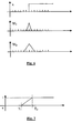
- Figure 3A shows a Haar wavelet at scale 1, time 0;
- Figure 3B shows a signal x(u);
- Figure 3C shows the product of the Haar wavelet of Figure 3A and the signal of Figure 3B (i.e. the wavelet multiple signal or wavelet coefficient);
- Figure 4A shows the Haar wavelet at scale 2, time 0;
- Figure 4B shows the signal x(u);
- Figure 4C shows the product of the Haar wavelet of Figure 4A and the signal of Figure 4B ;
- Figure 5A shows the Haar wavelet at scale 1, time 1;
- Figure 5B shows the signal x(u);
- Figure 5C shows the product of the Haar wavelet of Figure 5A and the signal of Figure 5B ;
- Figure 6 shows a signal x representing a transitional area in an image and corresponding wavelet coefficients at different scales
- Figure 7 shows an exemplary shrinkage function
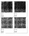
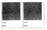
- Figures 8A to 8N are noise images captured by a digital camera at different ISO settings
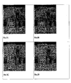
- Figures 9A to 9H show digital images captured by a digital camera at different ISO settings and corresponding denoised images generated by the apparatus of Figure 1 ;
- Figures 10A to 10C show another digital image captured by a digital camera and a corresponding denoised image generated by the apparatus of Figure 1 .
- apparatus 40 comprises a processing unit 44, random access memory (“RAM”) 48, non-volatile memory 52, a communication interface 56, a user interface 64 and a display 68, all in communication over a local bus 72.
- RAM random access memory
- non-volatile memory 52 non-volatile memory 52
- communication interface 56 communication interface 56
- user interface 64 user interface 64
- display 68 display 68
- a noise reduction application is stored in the non-volatile memory 52.
- the noise reduction application is retrieved from the non-volatile memory 52, loaded into the RAM 48 and executed by the processing unit 44 when the apparatus 40 is used to process images to remove noise therein.
- FIG. 2 is a flowchart showing the general method employed by the apparatus 40 in order to reduce noise in an image during execution of the noise reducing application.
- the noise reduction application employs wavelet decomposition, wavelet coefficient modification and wavelet reconstruction during the image denoising process.
- the image is wavelet decomposed using a Haar wavelet into wavelet detail spaces of different scales, with each wavelet detail space comprising a plurality of wavelet detail subbands (step 100).
- the wavelet detail subbands at each scale represent the details of the image at that scale.
- Each wavelet detail subband comprises a matrix of wavelet coefficients. Wavelet shrinkage ratios based on the energy feature space of the wavelet coefficients are then generated and normalized (step 102).
- the normalized wavelet shrinkage ratios are applied to the wavelet coefficients (step 104). By modifying the wavelet coefficients in this manner, noise in the image is suppressed without adversely effecting image details. The modified wavelet coefficients are then reconstructed thereby to yield the noise reduced image (step 106).
- the preservation of energy in wavelet coefficients allows wavelet coefficients to be used to measure discontinuities in images. For example, the energy of wavelet coefficients associated with homogenous regions in images is close to zero. The energy of wavelet coefficients associated with high transitional areas in images, such as for example edges (i.e. image detail), is however, very high.
- Figure 6 shows a signal x representing a transitional area in an image, such as for example an edge, and corresponding wavelet coefficients W 1 and W 2 representing the edge at different scales.
- the energy of the wavelet coefficients W 1 and W 2 does not decrease at higher scales.
- the noise reducing technique employed by apparatus 40 makes use of this different wavelet coefficient energy behavior to reduce effectively noise in images as will now be described.
- the image is initially wavelet decomposed into wavelet detail spaces at different scales, with each wavelet detail space comprising a plurality of wavelet detail subbands.
- each wavelet detail space comprising a plurality of wavelet detail subbands.
- the image is initially decomposed into four (4) wavelet subbands, namely high-high (HH), high-low (HL), low-high (LH) and low-low (LL) subbands.
- the HH, HL and LH subbands represent the wavelet detail subbands at level one (1).
- the LL subband which is the low frequency approximation, is then decomposed into HH, HL, LH and LL subbands at the next level two (2).
- the HH, HL and LH subbands represent the wavelet detail subbands at level two (2).
- the LL subband is then decomposed into HH, HL, LH and LL subbands at the next level three (3). This process continues until the J 0 -th level is reached.
- the LL subband at this level represents the coarsest approximation of the image and is substantially noise free.
- the feature energy space of the wavelet coefficients is determined.
- a shrinkage ratio for each of the wavelet coefficients is calculated (step 104) according to Equation (13) below:
- Shrinkage j p Shrinkage l HH p , Shrinkage l HL p , Shrinkage l LH p
- Shrinkage j HH p ⁇ 1 Feature Energy j HH p > K * TH j HH Feature Energy l HH p - K * TH j HH K * TH j HH - K * TL j HH 0 Feature Energy j HH p ⁇ K * TL j HH
- Shrinkage j HL p ⁇ 1 Feature Energy j HL p > K * TH j HL Feature Energy l HL p - K * TH j HL K * TH j HL - K * TL j HL 0 Feature Energy j HL p ⁇ K * TL
- the parameter K may be fixed or adjustable either manually or automatically.
- Figure 7 shows an exemplary shrinkage ratio.
- the modified or "shrunk" wavelet coefficients are then reconstructed to yield the noise reduced images at step 106.
- the thresholds TL j and TH j used during calculation of the shrinkage ratios assist in distinguishing between image noise and image detail and to maintain a balance between removing noise and maintaining image detail. If the feature energy calculated for a wavelet coefficient is less than the threshold TL j , the wavelet coefficient is deemed to represent noise. If the feature energy calculated for a wavelet coefficient is greater than the threshold TH j , the wavelet coefficient is deemed to represent image detail. Noise images are used in this embodiment to select the thresholds TL j and TH j at each scale.
- noise images at different ISO settings and a 1/3 EV stop were captured using a digital camera employing a Penguin® digital camera board produced by Seiko Epson Corporation as shown in Figures 8A and 8N .
- a 256x256 pixel sub-window of each noise image was extracted and the sub-windows were wavelet decomposed as described above.
- the noise energy level at 68% of accumulated feature energy was determined and used as threshold TL j HH .
- the noise energy level at 98% of the accumulated feature energy of the HH suband was also determined and used as threshold TH j HH .
- the thresholds TH j HL TL j LH TH j HL and TH j LH for the HL and LH subbands at scale j were obtained in a similar manner.
- the thresholds TL j and TH j for each scale were recorded and represent the noise profile of the image capture device for that scale. If desired, a histogram of the noise image feature energy at each scale may also be recorded to form a noise profile.
- Figures 9A to 9H show digital images captured by a digital camera at different ISO settings and corresponding denoised images generated by the apparatus 40.
- Figure 9A shows an image captured by a digital camera at an ISO setting equal to one-hundred (100) and Figure 9B shows the corresponding denoised image.
- Figure 9C shows an image captured by a digital camera at an ISO setting equal to two-hundred (200) and Figure 9D shows the corresponding denoised image.
- Figure 9E shows an image captured by a digital camera at an ISO setting equal to four-hundred (400) and Figure 9F shows the corresponding denoised image.
- Figure 9G shows an image captured by a digital camera at an ISO setting equal to six-hundred (600) and Figure 9H shows the corresponding denoised image.
- Figures 10A and 10C show another digital image captured by a digital camera and the corresponding denoised image generated by the apparatus 40.
- a sub-window of pixels in the image of Figure 10A is used to determine the thresholds TL j and TH j .
- the entire image is wavelet decomposed and then wavelet reconstructed following modification of the wavelet coefficients based on the energy of the wavelet coefficients.
- each channel of the image can be processed separately.
- the noise level is higher.
- the Y channel of the image may be used to obtain prior possibilities for edges.
- the noise reducing technique may be performed only on the Y of the images channel in order to reduce the processing time.
- Haar wavelet Although use of a Haar wavelet is discussed above, those of skill in the art will appreciate that other wavelets such as for example Daubechies, Coiflets or Symmlet wavelets may be used.
- the noise reducing technique is described above in a post-processing environment where images are processed downstream of the equipment used to capture the images.
- the noise reducing technique may be employed in image capture devices such for example digital cameras, digital video recorders etc. to process and noise reduce images. This image denoising may be performed automatically prior to image display or in response to user input.
- the noise reducing technique may be used to denoise images captured in a number of fields including for example, astronomy, medical imaging, radar imaging, natural photography etc.
- the noise reducing application may run independently or may be incorporated into other available image processing applications to provide enhanced functionality to those applications.
- the software application may comprise program modules including routines, programs, object components, data structures etc. and be embodied as computer-readable program code stored on a computer-readable medium.
- the computer-readable medium is any data storage device that can store data, which can thereafter be read by a computer system. Examples of computer-readable medium include for example read-only memory, random-access memory, hard disk drives, magnetic tape, CD-ROMs and other optical data storage devices.
- the computer-readable program code can also be distributed over a network including coupled computer systems so that the computer-readable program code is stored and executed in a distributed fashion.
Landscapes
- Engineering & Computer Science (AREA)
- Physics & Mathematics (AREA)
- General Physics & Mathematics (AREA)
- Theoretical Computer Science (AREA)
- Multimedia (AREA)
- Image Processing (AREA)
- Apparatus For Radiation Diagnosis (AREA)
- Picture Signal Circuits (AREA)
- Facsimile Image Signal Circuits (AREA)
Abstract
Description
- The present invention relates generally to image processing and in particular, to a method, apparatus and computer-readable medium embodying a computer program for reducing noise in an image using wavelet decomposition.
- Digital cameras have an ISO rating identifying their level of sensitivity to light. For most digital cameras, a default ISO 100 setting is normal although some digital cameras have default ISO settings as low as fifty (50). The PENGUIN® digital camera board produced by Seiko Epson Corporation has an ISO range between fourteen (14) and nine-hundred and ten (910) and a default ISO 50 setting. In high-end digital, single-lens reflex (SLR) cameras, even higher ISO settings are available. For example, in some digital SLR cameras, the default ISO setting can be set to 200, 400, 800 or even 3200.
- When increasing the ISO setting of a digital camera and hence, its sensitivity to light, the output of the digital camera sensor is amplified and so less light is needed during image capture. Unfortunately, undesired noise is also amplified resulting in more grainy pictures. Noise in general is introduced into images by both the digital camera sensor and the digital camera signal amplifier as a result of particular shooting conditions, image compression etc.
- In examining noise in images captured by digital cameras at high ISO settings, it has been found that noise generally takes two forms, namely luminance noise and chroma noise. Luminance noise gives images a grainy look when presented on an electronic display screen but is usually not visible when the images are printed. Chroma noise appears as random red and blue pixels and is typically less visible in images both on-screen and when printed. Chroma noise is most visible in smooth and/or dark areas of images and is more visible in red (R) and blue (B) channels. Chroma noise in the red and blue channels tends to contain more low and very low frequency components due to demosaicing and interpolation. Chroma noise also adversely affects color saturation and contrast.
- Many methods to remove noise from images have been considered. Some noise reduction methods, such as for example, anistopic diffusion, assume that white noise has been added to images and compensate for image degradation on the basis of this assumption. Unfortunately, noise in images captured by digital cameras having high ISO settings is not accurately modeled by this noise assumption and thus, these noise reducing methods have proven to be unsatisfactory.
- Wavelet methods for removing noise from images have gained in popularity. The Donoho-Johnstone method is a popular and efficient denoising method incorporating wavelets and makes use of soft or hard thresholds. During denoising of an image, the image is wavelet decomposed to generate wavelet coefficients representing the image detail. All of the wavelet coefficients below threshold levels are reduced to zero. Wavelet coefficients exceeding the threshold levels are either unmodified (hard) or reduced (soft). This method has proven to be most successful when the noise in the image generally conforms to expected Gaussian white noise. Unfortunately, this method requires the arbitrary a priori selection of the threshold levels. As a result, depending on the selected threshold levels, if the noise is not white noise, detail in the image may be lost, an insufficient amount of noise may be removed from the image or the noise may be improperly removed from the image.
- Other more sophisticated noise reducing algorithms have been considered but these noise reducing algorithms are expensive in terms of processing time. Many of these methods, similar to the anistropic diffusion method referred to above, incorporate assumed noise models and thus, unsuccessfully address noise when the noise does not accurately fit within the noise models.
- Still other techniques for reducing noise in images have been considered. For example,
U.S. Patent No. 6,163,619 to Maruo discloses a method in which an input digital image of an object is subjected to a Wavelet transform. An image energy quantity for a combined area of X-axis high pass information and Y-axis high pass information contained in the image data resulting from the Wavelet transform, is calculated. The object is deemed acceptable or faulty depending on whether the image energy quantity is below or above a given value. -
U.S. Patent No. 6,836,569 to Le Pennac et al. discloses a method and apparatus for processing an n-dimensional digitized signal using foveal processing, which constructs a sparse signal representation by taking advantage of the geometrical regularity of signal structures. Foveal coefficients are computed with one-dimensional inner products along trajectories of an n-directional trajectory list. A trajectory finder computes the n-directional trajectory list from the input n-dimensional signals, in order to choose optimal locations to compute the foveal coefficients. From the foveal coefficients, a foveal reconstruction processor recovers a signal approximation which has the same geometrical structures as the input signal along the trajectories and which is regular away from the trajectories. A foveal residue can be calculated as a difference with the input signal. A bandlet processor decorrelates the foveal coefficients by applying invertible linear operators along each trajectory. Bandlet coefficients are inner products between the signal and n-dimensional bandlet vectors elongated along the trajectories. A geometric processor computes geometric coefficients by decorrelating the coordinates of the trajectories with linear operators, to take advantage of their geometrical regularity. Setting small bandlet coefficients and small geometric coefficients to zero yields the sparse signal representation. -
U.S. Patent Application Publication No. 2003/0095206 to Wredenhagen et al. discloses a method for reducing noise in an image. During the method, a plurality of pixels along a predetermined contour is compared with a plurality of predefined patterns. The patterns represent visually significant patterns possible along the contour. A filter is selected from a predefined set of filters in accordance with the results of the comparison. -
U.S. Patent Application Publication No. 2004/0008904 to Lin et al . discloses a process for removing noise in an image by wavelet thresholding utilizing a discrete wavelet transform that decomposes the image into different resolution levels. A thresholding function is then applied in different resolution levels with different threshold values to eliminate insignificant wavelet coefficients which mainly correspond to noise in the image. An inverse discrete wavelet transform is applied to generate a noise-reduced image. The threshold values are based on the relationships between the noise standard deviations at different decomposition levels in the wavelet domain and the noise standard deviation of the image. -
U.S. Patent Application Publication No. 2004/0260169 to Sternnickel discloses a two-part method for non-linear de-noising (NLD) of magneto cardiograph or electrocardiograph time series signals by performing local projections in the reconstructed state space using a wavelet transform to identify and describe deterministic structures. Subspaces generated by deterministic processes are located and separated independently of their sources. -
U.S. Patent Application Publication No. 2004/0268096 to Master et al. discloses a digital imaging apparatus such as a digital camera, scanner, printer or dry copier having an optical sensor, an analog-to-digital converter, a plurality of computational elements, and an interconnection network. The optical sensor converts an object image into a detected image, which is then converted to digital image information by the analog-to-digital converter. The plurality of computational elements comprises a first computational element having a first fixed architecture and a second computational element having a second, different fixed architecture. The interconnection network is capable of providing a processed digital image from the digital image information by configuring and reconfiguring the computational elements in order to perform a plurality of different imaging functions. -
U.S. Patent Application Publication No. 2005/0100237 to Kong et al . discloses a method of filtering pixels in an image, by first partitioning the image into blocks. Edge blocks are then identified. A variance of intensity for each pixel in each edge block is subsequently determined. Each pixel in each edge block is then filtered with a filter that is dependant on the intensity variance of the pixel. -
U.S. Patent Application Publication No. 2005/40100241 to Kong et al. -
U.S. Patent Application Publication No. 2005/0207660 to Edgar discloses a method for removing artefacts to restore a block of data. During the method, one or more original transform coefficients of the data block are received and the original transform coefficients of the data block are quantized. An artefact reduction process is applied to the quantized original transform coefficients and one or more quantized data values representing the transform coefficients as altered by the artefact reduction process is adjusted, if necessary. The artefact reduction process is reapplied and the quantized data values are readjusted, enabling restoration of the block of data. -
U.S. Patent Application Publication No. 2005/0265633 to Piacentino et al . discloses a video processor that uses a low latency pyramid processing technique for fusing images from multiple sensors. The images from the multiple sensors are enhanced, warped into alignment, and then fused with one another in a manner that enables the fusing to occur within a single frame of video, i.e., sub-frame processing. The sub-frame processing results in a sub-frame delay between the moment of image capture and subsequent fused image display. -
U.S. Patent Application Publication No. 2005/0276515 to Shekter discloses an apparatus for analyzing the broadband noise content of a digital image. The apparatus comprises means for automatically identifying regions of originally constant color in the image by analyzing the variance of pixel values of regions of the image. The apparatus further comprises means for automatically detecting and discarding constant color regions deemed to be unrepresentative of the true noise content of the image, including underexposed and over-exposed regions. Selected constant color regions are then analyzed to generate a parametric or non-parametric model of the noise in the image, including frequency characteristics within and between channels and other characteristics such as phase, which might describe structured noise. - Although image noise reducing techniques are available, improvements are desired. It is therefore an object of the present invention to provide a novel method, apparatus and computer-readable medium embodying a computer program for reducing noise in an image using wavelet decomposition.
- Accordingly, in one aspect there is provided a method of reducing noise in an image comprising:
- decomposing the image to generate wavelet coefficients at different scales;
- modifying the wavelet coefficients based on the energy of the wavelet coefficients at said different scales; and
- reconstructing the image based on the modified wavelet coefficients.
- In one embodiment, the modifying is based on normalized inter-scale energy, single scale energy and weighted average single scale energy of the wavelet coefficients. The image is decomposed into wavelet detail spaces at different scales with each wavelet detail space comprising a plurality of wavelet detail subbands and each wavelet detail subband comprising a matrix of wavelet coefficients. The modifying may further be based on an adjustable parameter. The parameter may be manually adjustable and/or may be based on a function of an image capture device.
- The decomposing, modifying and reconstructing may be performed automatically upon image capture or downstream following image capture.
- The decomposing, modifying and reconstructing may be perfomed independently on one or more channels of the image. The one or more channels may comprise the Y channel of the image or the red and blue channels of the image.
- Accoding to another aspect there is provided an apparatus for reducing noise in an image comprising:
- memory storing said image; and
- processing structure decomposing the image to generate wavelet coefficients at different scales, modifying the wavelet coefficients based on the energy of the wavelet coefficients at the different scales and reconstructing the image based on the modified wavelet coefficients.
- According to yet another aspect there is provided a computer redeable medium embodying a computer program for reducing noise in an image, said computer program comprising:
- computer program code for decomposing the image to generate wavelet coefficients at different scales;
- computer program code for modifying the wavelet coefficients based on the energy of the wavelet coefficients at different scales; and
- computer program code for reconstructing the image based on the modified wavelet coefficients.
- Embodiments will now be described more fully with reference to the accompanying drawings in which:
-
Figure 1 is an apparatus for reducing noise in an image using wavelet decomposition; -
Figure 2 is a flowchart showing the steps performed by the apparatus ofFigure 1 in order to reduce noise in an image during execution of a noise reducing application; -
Figure 3A shows a Haar wavelet atscale 1,time 0; -
Figure 3B shows a signal x(u); -
Figure 3C shows the product of the Haar wavelet ofFigure 3A and the signal ofFigure 3B (i.e. the wavelet multiple signal or wavelet coefficient); -
Figure 4A shows the Haar wavelet atscale 2,time 0; -
Figure 4B shows the signal x(u); -
Figure 4C shows the product of the Haar wavelet ofFigure 4A and the signal ofFigure 4B ; -
Figure 5A shows the Haar wavelet atscale 1,time 1; -
Figure 5B shows the signal x(u); -
Figure 5C shows the product of the Haar wavelet ofFigure 5A and the signal ofFigure 5B ; -
Figure 6 shows a signal x representing a transitional area in an image and corresponding wavelet coefficients at different scales; -
Figure 7 shows an exemplary shrinkage function; -
Figures 8A to 8N are noise images captured by a digital camera at different ISO settings; -
Figures 9A to 9H show digital images captured by a digital camera at different ISO settings and corresponding denoised images generated by the apparatus ofFigure 1 ; and -
Figures 10A to 10C show another digital image captured by a digital camera and a corresponding denoised image generated by the apparatus ofFigure 1 . - Turning now to
Figure 1 , an apparatus for reducing noise in an image using wavelet decomposition is shown and is generally identified byreference numeral 40. As can be seen,apparatus 40 comprises aprocessing unit 44, random access memory ("RAM") 48,non-volatile memory 52, acommunication interface 56, auser interface 64 and adisplay 68, all in communication over alocal bus 72. A noise reduction application is stored in thenon-volatile memory 52. The noise reduction application is retrieved from thenon-volatile memory 52, loaded into theRAM 48 and executed by theprocessing unit 44 when theapparatus 40 is used to process images to remove noise therein. -
Figure 2 is a flowchart showing the general method employed by theapparatus 40 in order to reduce noise in an image during execution of the noise reducing application. In this embodiment, the noise reduction application employs wavelet decomposition, wavelet coefficient modification and wavelet reconstruction during the image denoising process. Initially during processing of an image to remove noise, the image is wavelet decomposed using a Haar wavelet into wavelet detail spaces of different scales, with each wavelet detail space comprising a plurality of wavelet detail subbands (step 100). The wavelet detail subbands at each scale represent the details of the image at that scale. Each wavelet detail subband comprises a matrix of wavelet coefficients. Wavelet shrinkage ratios based on the energy feature space of the wavelet coefficients are then generated and normalized (step 102). The normalized wavelet shrinkage ratios are applied to the wavelet coefficients (step 104). By modifying the wavelet coefficients in this manner, noise in the image is suppressed without adversely effecting image details. The modified wavelet coefficients are then reconstructed thereby to yield the noise reduced image (step 106). - Further specifies of the above image denoising technique employed by the
apparatus 40 during execution of the noise reducing application will be described. However before doing so, for ease of understanding, a brief discussion of wavelets will firstly be provided. As is well known, the wavelet transformation of an image allows the image to be viewed in multiple resolutions, with each resolution reflecting a different frequency. In digital signal processing terms, the wavelets function as high pass filters. During wavelet transformation of a signal x from u-space to t-space, wavelet coefficients W(j,t) are calculated according to Equation (1) below:
where: - j is a selected scale or level at time or location t; and
- ψj is the wavelet at scale j.
- The wavelet transformation provides a framework for analyzing an image at multiple resolutions, in other words, at multiple scales and locations or times. Energy is preserved in wavelet coefficients according to Equation (2) below:

where: - Wj is the wavelet detail space at level or scale j;
- VJo is the approximation space at level Jo; and
- j = 1, 2, ...Jo.
- The preservation of energy in wavelet coefficients allows wavelet coefficients to be used to measure discontinuities in images. For example, the energy of wavelet coefficients associated with homogenous regions in images is close to zero. The energy of wavelet coefficients associated with high transitional areas in images, such as for example edges (i.e. image detail), is however, very high.
- Analyzing the energy of wavelet coefficients at different scales shows that the energy of noise in images and the energy of detail in images, behave differently at higher scales. Specifically, the energy of noise wavelet coefficients at higher scales decreases dramatically while the energy of image detail wavelet coefficients does not.
- For example, consider signal e(x) to be white noise having a Gaussian distribution N(0, σ 2). The wavelet coefficients of the white noise signal e(x) at scale j and time k are calculated according to Equation (3) below:

where: - ψj is the wavelet at scale j.
- The energy We of the white noise wavelet coefficients is calculated according to Equation (4) below:


Figure 6 shows a signal x representing a transitional area in an image, such as for example an edge, and corresponding wavelet coefficients W1 and W2 representing the edge at different scales. The energy of the wavelet coefficients W1 and W2 does not decrease at higher scales.
The noise reducing technique employed byapparatus 40 makes use of this different wavelet coefficient energy behavior to reduce effectively noise in images as will now be described. - As mentioned previously, at
step 100 during processing of an input image to remove noise, the image is initially wavelet decomposed into wavelet detail spaces at different scales, with each wavelet detail space comprising a plurality of wavelet detail subbands. In this embodiment, as a Haar wavelet is employed, at level one (1) the image is initially decomposed into four (4) wavelet subbands, namely high-high (HH), high-low (HL), low-high (LH) and low-low (LL) subbands. The HH, HL and LH subbands represent the wavelet detail subbands at level one (1). The LL subband, which is the low frequency approximation, is then decomposed into HH, HL, LH and LL subbands at the next level two (2). The HH, HL and LH subbands represent the wavelet detail subbands at level two (2). The LL subband is then decomposed into HH, HL, LH and LL subbands at the next level three (3). This process continues until the J0-th level is reached. The LL subband at this level represents the coarsest approximation of the image and is substantially noise free. As a result, at each level j, a wavelet detail space Wj comprising wavelet detail subbands HH, HL and LH and expressed by
- At
step 102, the feature energy space of the wavelet coefficients is determined. The j-th level wavelet coefficients in the wavelet detail subbands are expressed according to Equation (8) below as:
where: - j=1...J0;
- p is a point at location (x,y) in the wavelet detail subband;
- x = 1...N
- y = 1... M; and
- N and M are the width and height of the wavelet detail subbands at level j.
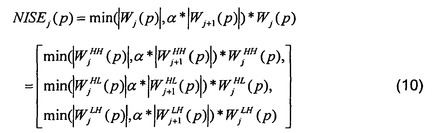
- α is the normalization ratio between adjacent scales.
- In addition to calculating the normalized inter-scale energy of the wavelet coefficients, the spatial relationship of noise and image detail is used to distinguish between image noise and image detail. Noise is spatially grainy while image details are spatially correlated and continuous. Accordingly, the weighted average single scale energy or "neighbor energy" of the wavelet coefficients is calculated according to Equation (11) below:

where: - weight(l) is a weight function equal to one (1); and
- N(p) is the neighborhood at location p.
- Jo is the highest scale of wavelet decomposition.
- Once the feature energy space has been determined at
step 102, a shrinkage ratio for each of the wavelet coefficients is calculated (step 104) according to Equation (13) below:
where:


K is a parameter that determines the level of noise reduction. The parameter K may be fixed or adjustable either manually or automatically. In this embodiment, the parameter K is expressed by Equation (14) below:
ISOsetting is the ISO value of the camera used to acquire image; and
NormallSO is the normal ISO setting of the camera.
Figure 7 shows an exemplary shrinkage ratio. - With the shrinkage ratios calculated at
step 104, the shrinkage ratios are then applied to the wavelet coefficients according to Equation (15) below:
step 106. - The thresholds TLj and THj used during calculation of the shrinkage ratios assist in distinguishing between image noise and image detail and to maintain a balance between removing noise and maintaining image detail. If the feature energy calculated for a wavelet coefficient is less than the threshold TLj, the wavelet coefficient is deemed to represent noise. If the feature energy calculated for a wavelet coefficient is greater than the threshold THj, the wavelet coefficient is deemed to represent image detail. Noise images are used in this embodiment to select the thresholds TLj and THj at each scale.
- In particular, during determination of the thresholds TLj and THj, noise images at different ISO settings and a 1/3 EV stop were captured using a digital camera employing a Penguin® digital camera board produced by Seiko Epson Corporation as shown in
Figures 8A and8N . A 256x256 pixel sub-window of each noise image was extracted and the sub-windows were wavelet decomposed as described above. For each sub-window, the feature energy of each wavelet coefficient was calculated according to Equation (16) below:


-
Figures 9A to 9H show digital images captured by a digital camera at different ISO settings and corresponding denoised images generated by theapparatus 40. In particular,Figure 9A shows an image captured by a digital camera at an ISO setting equal to one-hundred (100) andFigure 9B shows the corresponding denoised image.Figure 9C shows an image captured by a digital camera at an ISO setting equal to two-hundred (200) andFigure 9D shows the corresponding denoised image.Figure 9E shows an image captured by a digital camera at an ISO setting equal to four-hundred (400) andFigure 9F shows the corresponding denoised image.Figure 9G shows an image captured by a digital camera at an ISO setting equal to six-hundred (600) andFigure 9H shows the corresponding denoised image. -
Figures 10A and10C show another digital image captured by a digital camera and the corresponding denoised image generated by theapparatus 40. In this example, a sub-window of pixels in the image ofFigure 10A , as shown inFigure 10B , is used to determine the thresholds TLj and THj. - In the above embodiment, the entire image is wavelet decomposed and then wavelet reconstructed following modification of the wavelet coefficients based on the energy of the wavelet coefficients. As the noise corruption in the red, green and blue channels is typically different, if desired each channel of the image can be processed separately. Often, in the red and blue channels, the noise level is higher. The Y channel of the image may be used to obtain prior possibilities for edges. Alternatively, when processing color images, the noise reducing technique may be performed only on the Y of the images channel in order to reduce the processing time.
- Although use of a Haar wavelet is discussed above, those of skill in the art will appreciate that other wavelets such as for example Daubechies, Coiflets or Symmlet wavelets may be used.
- The noise reducing technique is described above in a post-processing environment where images are processed downstream of the equipment used to capture the images. Those of skill in the art will however appreciate that the noise reducing technique may be employed in image capture devices such for example digital cameras, digital video recorders etc. to process and noise reduce images. This image denoising may be performed automatically prior to image display or in response to user input. Those of skill in the art will also appreciate that the noise reducing technique may be used to denoise images captured in a number of fields including for example, astronomy, medical imaging, radar imaging, natural photography etc.
- The noise reducing application may run independently or may be incorporated into other available image processing applications to provide enhanced functionality to those applications. The software application may comprise program modules including routines, programs, object components, data structures etc. and be embodied as computer-readable program code stored on a computer-readable medium. The computer-readable medium is any data storage device that can store data, which can thereafter be read by a computer system. Examples of computer-readable medium include for example read-only memory, random-access memory, hard disk drives, magnetic tape, CD-ROMs and other optical data storage devices. The computer-readable program code can also be distributed over a network including coupled computer systems so that the computer-readable program code is stored and executed in a distributed fashion.
- Although particular embodiments have been described, those of skill in the art will appreciate that variations and modifications may be made without departing from the spirit and scope thereof as defined by the appended claims.

As is known, the Haar wavelet is orthonormal and can be used to define a Hilbert basis, that is, a complete orthonormal system for a Hilbert space of square integratable functions.

where:

where:
Claims (27)
- A method of reducing noise in an image comprising:decomposing the image to generate wavelet coefficients at different scales;modifying the wavelet coefficients based on the energy of the wavelet coefficients at said different scales; andreconstructing the image based on the modified wavelet coefficients.
- The method of claim 1 wherein the modifying is based on at least one of inter-scale energy, single scale energy and average single scale energy of said wavelet coefficients.
- The method of claim 2 wherein the modifying is based on normalized inter-scale energy, single scale energy and weighted average single scale energy of said wavelet coefficients.
- The method of claim 3 wherein during decomposing, said image is decomposed into wavelet detail spaces at different scales, each wavelet detail space comprising a plurality of wavelet detail subbands and each wavelet detail subband comprising a matrix of wavelet coefficients.
- The method of claim 4 wherein during the modifying, the feature energy of the wavelet coefficients is detemined according to:

where NISEj (p) is the normalized inter-scale energy, SSEj (p) is the single scale energy, NeighborEnergy j (p) is the weighted average single scale energy, j is the scale and p is location (x,y) in each wavelet detail subband. - The method of claim 5 wherein said modifying is further based on an adjustable parameter.
- The method of claim 6 wherein during said modifying each wavelet coefficient is multiplied by a shrinkage ratio of the form:

where K is the adjustable parameter and THj and TLj are thresholds for scale j. - The method of claim 7 wherein K is of the form:

where ISOsefting is the ISO value of the image capture device used to capture the image and NormallSO is the typical ISO setting of the image capture device. - The method of claim 8 wherein said thresholds are detemined by examining noise images captured at different ISO settings.
- The method of claim 1 wherein said decomposing, modifying and reconstructing are performed independently on one or more channels of said image.
- The method of claim 10 wherein said one more channels comprises the Y channel of said image.
- The method of claim 10 wherein said one or more channels comprises red and blue channels of said image.
- The method of claim 9 wherein said thresholds are based on the feature energy of wavelet coefficients of said noise images.
- The method of claim 1 wherein said decomposing, modifying and reconstructing are performed automatically upon image capture.
- The method of claim 4 wherein said decomposing, modifying and reconstructing are performed automatically upon image capture.
- The method of claim 10 wherein the modifying is based on at least one of inter-scale energy, single scale energy and average single scale energy of said wavelet coefficients.
- The method of claim 16 wherein the modifying is based on normalized inter-scale energy, single scale energy and weighted average single scale energy of said wavelet coefficients.
- The method of claim 17 wherein during decomposing, said image is decomposed into wavelet detail spaces at different scales, each wavelet detail space comprising a plurality of wavelet detail subbands and each wavelet detail subband comprising a matrix of wavelet coefficients.
- An apparatus for reducing noise in an image comprising:memory storing said image; andprocessing structure decomposing the image to generate wavelet coefficients at different scales, modifying the wavelet coefficients based on the energy of the wavelet coefficients at the different scales and reconstructing the image based on the modified wavelet coefficients.
- An apparatus according to claim 19 wherein said processing structure modifies the wavelet coefficients based on at least one of inter-scale energy, single scale energy and average single scale energy of the wavelet coefficients.
- An apparatus according to claim 20 wherein said processing structure modifies the wavelet coefficients based on normalized inter-scale energy, single scale energy and weighted average single scale energy of the wavelet coefficients.
- An apparatus according to claim 21 wherein said processing structure decomposes said image into wavelet detail spaces at different scales, each wavelet detail space comprising a plurality of wavelet detail subbands and each wavelet detail subband comprising a matrix of wavelet coefficient.
- An apparatus according to claim 22 wherein the processing structure performs the decomposing, modifying and reconstructing independently on one or more channels of said image.
- An apparatus according to claim 22 wherein the apparatus receives said image from an image capture device.
- An apparatus according to claim 19 wherein the apparatus is embodied in an image capture device.
- An apparatus according to claim 25 wherein said image capture device is a digital camera.
- A computer readable medium embodying a computer program for reducing noise in an image, said computer program comprising:computer program code for decomposing the image to generate wavelet coefficients at different scales;computer program code for modifying the wavelet coefficients based on the energy of the wavelet coefficients at different scales; andcomputer program code for reconstructing the image based on the modified wavelet coefficients.
Applications Claiming Priority (1)
| Application Number | Priority Date | Filing Date | Title |
|---|---|---|---|
| US11/620,288 US7778484B2 (en) | 2007-01-05 | 2007-01-05 | Method and apparatus for reducing noise in an image using wavelet decomposition |
Publications (2)
| Publication Number | Publication Date |
|---|---|
| EP1942461A2 true EP1942461A2 (en) | 2008-07-09 |
| EP1942461A3 EP1942461A3 (en) | 2011-09-14 |
Family
ID=39204791
Family Applications (1)
| Application Number | Title | Priority Date | Filing Date |
|---|---|---|---|
| EP07016778A Withdrawn EP1942461A3 (en) | 2007-01-05 | 2007-08-27 | Method and apparatus for reducing noise in an image using wavelet decomposition |
Country Status (3)
| Country | Link |
|---|---|
| US (1) | US7778484B2 (en) |
| EP (1) | EP1942461A3 (en) |
| JP (1) | JP2008171402A (en) |
Cited By (2)
| Publication number | Priority date | Publication date | Assignee | Title |
|---|---|---|---|---|
| CN111681243A (en) * | 2020-08-17 | 2020-09-18 | 广东利元亨智能装备股份有限公司 | Welding image processing method, device and electronic device |
| CN112991224A (en) * | 2021-04-07 | 2021-06-18 | 李�杰 | Image denoising algorithm based on improved wavelet threshold function |
Families Citing this family (21)
| Publication number | Priority date | Publication date | Assignee | Title |
|---|---|---|---|---|
| US8761504B2 (en) * | 2006-11-29 | 2014-06-24 | President And Fellows Of Harvard College | Spatio-spectral sampling paradigm for imaging and a novel color filter array design |
| WO2008067479A1 (en) * | 2006-11-29 | 2008-06-05 | President And Fellows Of Harvard College | A framework for wavelet-based analysis and processing of color filter array images with applications to denoising and demosaicing |
| KR101379256B1 (en) * | 2007-07-09 | 2014-04-02 | 삼성전자주식회사 | Method and apparatus for compensating signal distortion by noise |
| KR101552680B1 (en) * | 2009-03-09 | 2015-09-14 | 삼성전자 주식회사 | Noise reduction apparatus and method |
| KR101618298B1 (en) * | 2009-10-23 | 2016-05-09 | 삼성전자주식회사 | High ISO image generating apparatus and method |
| CN101847257B (en) * | 2010-06-10 | 2012-06-20 | 上海电力学院 | Image denoising method based on non-local means and multi-level directional images |
| CN101900674A (en) * | 2010-07-02 | 2010-12-01 | 天津大学 | A Wavelet Filtering Method for Noise Suppression of Carbon Dioxide Concentration Detection Signal |
| US9836433B1 (en) * | 2012-04-02 | 2017-12-05 | Rockwell Collins, Inc. | Image processing using multiprocessor discrete wavelet transform |
| KR102074857B1 (en) * | 2012-09-26 | 2020-02-10 | 삼성전자주식회사 | Proximity sensor and proximity sensing method using design vision sensor |
| US8879863B1 (en) * | 2013-05-07 | 2014-11-04 | Qualcomm Technologies, Inc. | Method for determining noise level |
| US10249065B2 (en) * | 2015-05-08 | 2019-04-02 | Max-Planck-Gesellschaft Zur Foerderung Der Wissenschaften E.V | Method and device for magnetic resonance imaging with improved sensitivity by noise reduction |
| US9858495B2 (en) * | 2015-06-23 | 2018-01-02 | Hong Kong Applied Science And Technology Research | Wavelet-based image decolorization and enhancement |
| CN109727200A (en) * | 2017-10-30 | 2019-05-07 | 上海交通大学 | A method and system for denoising images with similar block stacking based on Bayesian tensor decomposition |
| KR101958194B1 (en) | 2017-11-30 | 2019-03-15 | 인천대학교 산학협력단 | Apparatus and method for contrast enhancement in transform domain |
| CN109345475B (en) * | 2018-09-19 | 2021-07-23 | 长安大学 | A UAV remote sensing mountain highway image fusion filtering method |
| CN109443367B (en) * | 2018-12-27 | 2022-03-15 | 合肥工业大学 | A RFID Localization Method Based on Mean Clustering Random Particle Swarm Algorithm |
| CN111612707B (en) * | 2020-04-30 | 2023-04-18 | 杭州电子科技大学 | Neural network image denoising method based on wavelet transformation |
| CN112084845B (en) * | 2020-07-30 | 2023-05-02 | 中国人民解放军63892部队 | Low-frequency 1/f noise elimination method based on multi-scale wavelet coefficient autocorrelation |
| CN113324918B (en) * | 2021-01-26 | 2023-01-24 | 核工业北京地质研究院 | A Rock Spectral Denoising Method |
| CN113435855B (en) * | 2021-07-05 | 2022-05-20 | 广州市市政集团有限公司 | Construction information management system based on 5G communication |
| CN117495700B (en) * | 2023-09-22 | 2024-08-16 | 深圳光现科技有限公司 | Method for processing received signal of optical device |
Family Cites Families (24)
| Publication number | Priority date | Publication date | Assignee | Title |
|---|---|---|---|---|
| US5453945A (en) * | 1994-01-13 | 1995-09-26 | Tucker; Michael R. | Method for decomposing signals into efficient time-frequency representations for data compression and recognition |
| US5802369A (en) * | 1996-04-22 | 1998-09-01 | The United States Of America As Represented By The Secretary Of The Navy | Energy-based wavelet system and method for signal compression and reconstruction |
| TW343308B (en) | 1996-10-04 | 1998-10-21 | Adoban Tesuto Kk | Image processing method |
| US5953388A (en) * | 1997-08-18 | 1999-09-14 | George Mason University | Method and apparatus for processing data from a tomographic imaging system |
| US6058214A (en) * | 1998-01-20 | 2000-05-02 | At&T Corp. | Compression of partially masked still images |
| US7068851B1 (en) * | 1999-12-10 | 2006-06-27 | Ricoh Co., Ltd. | Multiscale sharpening and smoothing with wavelets |
| US6944350B2 (en) * | 1999-12-17 | 2005-09-13 | Utah State University | Method for image coding by rate-distortion adaptive zerotree-based residual vector quantization and system for effecting same |
| CA2309002A1 (en) | 2000-05-23 | 2001-11-23 | Jonathan Martin Shekter | Digital film grain reduction |
| US6836569B2 (en) | 2001-04-13 | 2004-12-28 | Erwan Le Pennec | Method and apparatus for processing or compressing n-dimensional signals by foveal filtering along trajectories |
| US7206459B2 (en) * | 2001-07-31 | 2007-04-17 | Ricoh Co., Ltd. | Enhancement of compressed images |
| US6933983B2 (en) | 2001-09-10 | 2005-08-23 | Jaldi Semiconductor Corp. | System and method for reducing noise in images |
| AU2002336643A1 (en) | 2001-09-21 | 2003-04-01 | Cardiomag Imaging, Inc. | Nonlinear noise reduction for magnetocardiograms using wavelet transforms |
| JP2004127064A (en) * | 2002-10-04 | 2004-04-22 | Konica Minolta Holdings Inc | Image processing method, image processor, image processing program and image recording device |
| JP2004242285A (en) * | 2003-01-14 | 2004-08-26 | Fuji Photo Film Co Ltd | Noise suppression processing method, apparatus and program |
| US7609297B2 (en) | 2003-06-25 | 2009-10-27 | Qst Holdings, Inc. | Configurable hardware based digital imaging apparatus |
| US7260272B2 (en) | 2003-07-10 | 2007-08-21 | Samsung Electronics Co.. Ltd. | Method and apparatus for noise reduction using discrete wavelet transform |
| KR100547853B1 (en) * | 2003-07-28 | 2006-01-31 | 삼성전자주식회사 | Discrete wavelet transform apparatus and method for adaptively encoding still images based on energy of each block |
| US7551792B2 (en) | 2003-11-07 | 2009-06-23 | Mitsubishi Electric Research Laboratories, Inc. | System and method for reducing ringing artifacts in images |
| JP4339671B2 (en) * | 2003-11-27 | 2009-10-07 | オリンパス株式会社 | Imaging device |
| US20050207660A1 (en) | 2004-03-16 | 2005-09-22 | Sozotek, Inc. | System and method for reduction of compressed image artifacts |
| US7377170B2 (en) * | 2004-04-08 | 2008-05-27 | University Of South Florida | System and method for the identification of chemical mechanical planarization defects |
| US20050265633A1 (en) | 2004-05-25 | 2005-12-01 | Sarnoff Corporation | Low latency pyramid processor for image processing systems |
| US7406396B2 (en) * | 2004-11-08 | 2008-07-29 | University Of South Florida | System and method for online end point detection for use in chemical mechanical planarization |
| US7391915B1 (en) * | 2005-08-12 | 2008-06-24 | Texas Instruments Incorporated | Cache friendly method for performing inverse discrete wavelet transform |
-
2007
- 2007-01-05 US US11/620,288 patent/US7778484B2/en active Active
- 2007-08-27 EP EP07016778A patent/EP1942461A3/en not_active Withdrawn
- 2007-11-28 JP JP2007306942A patent/JP2008171402A/en not_active Withdrawn
Cited By (2)
| Publication number | Priority date | Publication date | Assignee | Title |
|---|---|---|---|---|
| CN111681243A (en) * | 2020-08-17 | 2020-09-18 | 广东利元亨智能装备股份有限公司 | Welding image processing method, device and electronic device |
| CN112991224A (en) * | 2021-04-07 | 2021-06-18 | 李�杰 | Image denoising algorithm based on improved wavelet threshold function |
Also Published As
| Publication number | Publication date |
|---|---|
| US7778484B2 (en) | 2010-08-17 |
| EP1942461A3 (en) | 2011-09-14 |
| JP2008171402A (en) | 2008-07-24 |
| US20080166064A1 (en) | 2008-07-10 |
Similar Documents
| Publication | Publication Date | Title |
|---|---|---|
| EP1942461A2 (en) | Method and apparatus for reducing noise in an image using wavelet decomposition | |
| EP4109392B1 (en) | Image processing method and image processing device | |
| US7181086B2 (en) | Multiresolution method of spatially filtering a digital image | |
| US7386181B2 (en) | Image display apparatus | |
| US7551792B2 (en) | System and method for reducing ringing artifacts in images | |
| US8427559B2 (en) | Image data processing method by reducing image noise, and camera integrating means for implementing said method | |
| US7280703B2 (en) | Method of spatially filtering a digital image using chrominance information | |
| US7916940B2 (en) | Processing of mosaic digital images | |
| US6801672B1 (en) | Removing noise from a color image using wavelets | |
| KR101901602B1 (en) | Apparatus and method for noise removal in a digital photograph | |
| CN101816017B (en) | Image processing device and program | |
| JP7362297B2 (en) | Image processing device, image processing method, and program | |
| EP1223550A2 (en) | Method for detecting skin color in a digital image | |
| EP1308889A2 (en) | Method of spatially filtering digital images for noise removal, noise estimation or digital image enhancement | |
| CN1985274A (en) | Method, system and program module for restoring color components in an image model | |
| EP1840830B1 (en) | Image processing method | |
| US11915392B2 (en) | Image enhancement method and apparatus | |
| US8004586B2 (en) | Method and apparatus for reducing noise of image sensor | |
| US8942477B2 (en) | Image processing apparatus, image processing method, and program | |
| JP2002269558A (en) | Method of calculating noise from digital image using color cross correlation statistics | |
| US7522782B2 (en) | Digital image denoising | |
| US9111339B1 (en) | System and method for reducing noise from an image | |
| Rabie | Adaptive hybrid mean and median filtering of high-ISO long-exposure sensor noise for digital photography | |
| Safonov et al. | Adaptive sharpening of photos | |
| He et al. | A novel hybrid model framework to blind color image deconvolution |
Legal Events
| Date | Code | Title | Description |
|---|---|---|---|
| PUAI | Public reference made under article 153(3) epc to a published international application that has entered the european phase |
Free format text: ORIGINAL CODE: 0009012 |
|
| AK | Designated contracting states |
Kind code of ref document: A2 Designated state(s): AT BE BG CH CY CZ DE DK EE ES FI FR GB GR HU IE IS IT LI LT LU LV MC MT NL PL PT RO SE SI SK TR |
|
| AX | Request for extension of the european patent |
Extension state: AL BA HR MK RS |
|
| PUAL | Search report despatched |
Free format text: ORIGINAL CODE: 0009013 |
|
| AK | Designated contracting states |
Kind code of ref document: A3 Designated state(s): AT BE BG CH CY CZ DE DK EE ES FI FR GB GR HU IE IS IT LI LT LU LV MC MT NL PL PT RO SE SI SK TR |
|
| AX | Request for extension of the european patent |
Extension state: AL BA HR MK RS |
|
| RIC1 | Information provided on ipc code assigned before grant |
Ipc: G06T 5/00 20060101AFI20110810BHEP |
|
| AKY | No designation fees paid | ||
| REG | Reference to a national code |
Ref country code: DE Ref legal event code: R108 |
|
| REG | Reference to a national code |
Ref country code: DE Ref legal event code: R108 Effective date: 20120523 |
|
| STAA | Information on the status of an ep patent application or granted ep patent |
Free format text: STATUS: THE APPLICATION IS DEEMED TO BE WITHDRAWN |
|
| 18D | Application deemed to be withdrawn |
Effective date: 20120315 |