EP1942353A1 - Method and system for producing an interpretive airborne radar map - Google Patents
Method and system for producing an interpretive airborne radar map Download PDFInfo
- Publication number
- EP1942353A1 EP1942353A1 EP08100130A EP08100130A EP1942353A1 EP 1942353 A1 EP1942353 A1 EP 1942353A1 EP 08100130 A EP08100130 A EP 08100130A EP 08100130 A EP08100130 A EP 08100130A EP 1942353 A1 EP1942353 A1 EP 1942353A1
- Authority
- EP
- European Patent Office
- Prior art keywords
- feature
- aircraft
- terrain
- vector
- intersected
- Prior art date
- Legal status (The legal status is an assumption and is not a legal conclusion. Google has not performed a legal analysis and makes no representation as to the accuracy of the status listed.)
- Withdrawn
Links
- 238000000034 method Methods 0.000 title claims abstract description 15
- 239000013598 vector Substances 0.000 claims abstract description 30
- 238000010586 diagram Methods 0.000 description 4
- 238000013507 mapping Methods 0.000 description 2
- 239000003973 paint Substances 0.000 description 2
Images

Classifications
-
- G—PHYSICS
- G01—MEASURING; TESTING
- G01S—RADIO DIRECTION-FINDING; RADIO NAVIGATION; DETERMINING DISTANCE OR VELOCITY BY USE OF RADIO WAVES; LOCATING OR PRESENCE-DETECTING BY USE OF THE REFLECTION OR RERADIATION OF RADIO WAVES; ANALOGOUS ARRANGEMENTS USING OTHER WAVES
- G01S13/00—Systems using the reflection or reradiation of radio waves, e.g. radar systems; Analogous systems using reflection or reradiation of waves whose nature or wavelength is irrelevant or unspecified
- G01S13/88—Radar or analogous systems specially adapted for specific applications
- G01S13/93—Radar or analogous systems specially adapted for specific applications for anti-collision purposes
- G01S13/933—Radar or analogous systems specially adapted for specific applications for anti-collision purposes of aircraft or spacecraft
- G01S13/935—Radar or analogous systems specially adapted for specific applications for anti-collision purposes of aircraft or spacecraft for terrain-avoidance
-
- G—PHYSICS
- G01—MEASURING; TESTING
- G01S—RADIO DIRECTION-FINDING; RADIO NAVIGATION; DETERMINING DISTANCE OR VELOCITY BY USE OF RADIO WAVES; LOCATING OR PRESENCE-DETECTING BY USE OF THE REFLECTION OR RERADIATION OF RADIO WAVES; ANALOGOUS ARRANGEMENTS USING OTHER WAVES
- G01S7/00—Details of systems according to groups G01S13/00, G01S15/00, G01S17/00
- G01S7/02—Details of systems according to groups G01S13/00, G01S15/00, G01S17/00 of systems according to group G01S13/00
- G01S7/04—Display arrangements
Definitions
- the present invention provides systems and methods for identifying and uniquely displaying ground features (terrain/obstacles) that are shadowed from an aircrafts radar system.
- An example system includes one or more aircraft information sources, a database that stores three-dimensional terrain/obstacle data, a display device, and a processor in data communication with the one or more aircraft information sources and the database.
- the processor receives aircraft position, heading and altitude information from the one or more aircraft information sources.
- the processor projects a vector in a three-dimensional digital space onto the three-dimensional terrain/obstacle data stored in the database based on the received aircraft position, heading and altitude information to determine if the projected vector intersects more than one terrain feature.
- a feature is indicated as being shadowed if the feature is intersected by the vector and the feature is further away from the aircraft than another feature that is also intersected by the vector. Shadowed features are then uniquely displayed on the display device.
- the processor repeats this analysis for subsequent vectors.
- the display device simultaneously displays a radar image and the uniquely displayed indicated features.
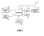
- FIGURE 1 illustrates a schematic diagram of an example system formed in accordance with an embodiment of the present invention
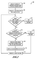
- FIGURE 2 illustrates a flow diagram performed by one or more components of the system shown in FIGURE 1 ;
- FIGURE 3 illustrates a side view of an aircraft radar mapping a section of terrain
- FIGURE 4 illustrates an example screen shot of a radar map display formed in accordance with an embodiment of the present invention.
- FIGURE 1 illustrates a block diagram of an example system 20 for improving the information displayed of a radar display image.
- the example system 20 includes a processor 22, a terrain/obstacle three-dimensional database 28, a radar system 32, a display 34, and one or more aircraft information sources, such as an air data computer (ADC) 26, a flight management system (FMS) 24 or a positioning system 30, such as a Global Positioning System (GPS).
- ADC air data computer
- FMS flight management system
- GPS Global Positioning System
- the processor 22 is in data communication with the terrain database 28, the radar system 32, the display 34 and the aircraft information sources.
- the processor 22 receives aircraft information, such as position, heading, and altitude from one or more of the FMS 24, ADC 26, or positioning system 30.
- the processor 22 determines if any terrain data from the terrain database 28 is shadowed by other terrain data based on a vector projected from the aircraft's position to the terrain of the database 28 based on the received aircraft information.
- the processor 22 then produces a radar image for display on the display 34.
- the radar image includes radar information received from the radar system 32 that is enhanced with image features that identify areas of terrain that are in a radar shadow as determined by the processor 22.
- FIGURE 2 illustrates a flow diagram of an example process 100 as performed by the processor 22 of FIGURE 1 .
- the processor 22 receives aircraft position, heading and altitude information from one or more of the aircraft information sources.
- a vector is projected (i.e., virtually/mathematically) in a digital/virtual three-dimensional (3D) environment from the received aircraft position, heading and altitude to the 3D terrain data that is stored in the terrain database 28.
- the vector simulates a radar signal produced by the radar system 32.
- the example process 100 determines if the vector intersects more than one feature of the terrain database. If the vector intersects only one terrain feature, then shadowing is determined not to occur, see block 112.
- the example process 100 goes to decision block 114 which determines if the intersected terrain feature that is closest to the aircraft is a building or some other manmade structure. If the closest intersected terrain feature is not a building, then the other terrain feature(s) that is intersected by the vector is indicated as being in the radar shadow of the closest intersected terrain feature, see block 116. The feature that is indicated as shadowed is then displayed on the radar display 34 in a unique manner along with a radar image, see block 118. If at the decision block 114 the closest intersected terrain feature is a building, then no shadowing of subsequent intersected terrain features is indicated, see block 122.
- the example process 100 projects a next vector at a block 124 and returns to the decision block 110.
- the example process 100 is repeated as long as the radar system is activated, or the terrain shadowing feature is activated, or as desired by the flight crew or system designer. Projection of vectors and analysis may be performed.
- FIGURE 3 illustrates a side view of a graphical illustration of terrain that would actually be identified as shadowed in a terrain shadowing situation.
- an aircraft 200 is flying over terrain that includes a mountain 204. Behind the mountain 204 is an area of terrain 206 that a radar system of the aircraft 200 is not able to paint. Therefore, in this example the processor 22 uniquely identifies the terrain area 206 as shadowed terrain and displays this area of terrain 206 with the corresponding radar image. Indicating the area of terrain as shadowed may also be included in other ground type displays.
- FIGURE 4 illustrates an example of a radar image 220 that is performed in accordance with the process 100 of FIGURE 2 as performed by the system 20 of FIGURE 1 .
- the radar image 220 includes radar return features 224 and 226 that are produced by the radar system 32.
- the radar feature 224 is identified in the terrain database 28 as buildings or a city.
- terrain behind the feature 224 is not identified as shadowed.
- the terrain behind manmade obstacles or buildings may be identified as shadowed and, thus, displayed as such.
- the feature 226 is identified as terrain.
- the area 228 located behind the terrain 226 is identified as shadowed by the feature 226 and, thus, is indicated differently on the display 220.
- the air crew can easily distinguish between terrain that is visible to the radar (226) and terrain this is not visible (228).
- the processor 22 may identify terrain or obstacles as shadowed if they are determined to be located behind an obstacle and thus uniquely present it on the display 34.
Landscapes
- Engineering & Computer Science (AREA)
- Radar, Positioning & Navigation (AREA)
- Remote Sensing (AREA)
- Physics & Mathematics (AREA)
- Computer Networks & Wireless Communication (AREA)
- General Physics & Mathematics (AREA)
- Aviation & Aerospace Engineering (AREA)
- Electromagnetism (AREA)
- Traffic Control Systems (AREA)
- Radar Systems Or Details Thereof (AREA)
- Instructional Devices (AREA)
Abstract
Description
- Present airborne radar systems produce valuable information to flight crews. When radar mapping the earth, the flight crew can clearly see all terrain and man-made obstacles that the radar system paints. However, radars are limited by line of sight and, therefore, produce no information of regions that are shadowed by terrain or other features.
- Therefore, there exists a need for improving the information presented on a radar display.
- The present invention provides systems and methods for identifying and uniquely displaying ground features (terrain/obstacles) that are shadowed from an aircrafts radar system.
- An example system includes one or more aircraft information sources, a database that stores three-dimensional terrain/obstacle data, a display device, and a processor in data communication with the one or more aircraft information sources and the database. The processor receives aircraft position, heading and altitude information from the one or more aircraft information sources. The processor projects a vector in a three-dimensional digital space onto the three-dimensional terrain/obstacle data stored in the database based on the received aircraft position, heading and altitude information to determine if the projected vector intersects more than one terrain feature. A feature is indicated as being shadowed if the feature is intersected by the vector and the feature is further away from the aircraft than another feature that is also intersected by the vector. Shadowed features are then uniquely displayed on the display device. The processor repeats this analysis for subsequent vectors.
- In one aspect of the invention, the display device simultaneously displays a radar image and the uniquely displayed indicated features.
- Preferred and alternative embodiments of the present invention are described in detail below with reference to the following drawings:
-
FIGURE 1 illustrates a schematic diagram of an example system formed in accordance with an embodiment of the present invention; -
FIGURE 2 illustrates a flow diagram performed by one or more components of the system shown inFIGURE 1 ; -
FIGURE 3 illustrates a side view of an aircraft radar mapping a section of terrain; and -
FIGURE 4 illustrates an example screen shot of a radar map display formed in accordance with an embodiment of the present invention. -
FIGURE 1 illustrates a block diagram of anexample system 20 for improving the information displayed of a radar display image. Theexample system 20 includes aprocessor 22, a terrain/obstacle three-dimensional database 28, aradar system 32, adisplay 34, and one or more aircraft information sources, such as an air data computer (ADC) 26, a flight management system (FMS) 24 or apositioning system 30, such as a Global Positioning System (GPS). - The
processor 22 is in data communication with theterrain database 28, theradar system 32, thedisplay 34 and the aircraft information sources. Theprocessor 22 receives aircraft information, such as position, heading, and altitude from one or more of the FMS 24, ADC 26, orpositioning system 30. Using the received aircraft information, theprocessor 22 determines if any terrain data from theterrain database 28 is shadowed by other terrain data based on a vector projected from the aircraft's position to the terrain of thedatabase 28 based on the received aircraft information. Theprocessor 22 then produces a radar image for display on thedisplay 34. The radar image includes radar information received from theradar system 32 that is enhanced with image features that identify areas of terrain that are in a radar shadow as determined by theprocessor 22. -
FIGURE 2 illustrates a flow diagram of anexample process 100 as performed by theprocessor 22 ofFIGURE 1 . First at ablock 104, theprocessor 22 receives aircraft position, heading and altitude information from one or more of the aircraft information sources. Next at ablock 106, a vector is projected (i.e., virtually/mathematically) in a digital/virtual three-dimensional (3D) environment from the received aircraft position, heading and altitude to the 3D terrain data that is stored in theterrain database 28. The vector simulates a radar signal produced by theradar system 32. At adecision block 110, theexample process 100 determines if the vector intersects more than one feature of the terrain database. If the vector intersects only one terrain feature, then shadowing is determined not to occur, see block 112. If the vector does intersect more than one terrain feature, then theexample process 100 goes todecision block 114 which determines if the intersected terrain feature that is closest to the aircraft is a building or some other manmade structure. If the closest intersected terrain feature is not a building, then the other terrain feature(s) that is intersected by the vector is indicated as being in the radar shadow of the closest intersected terrain feature, seeblock 116. The feature that is indicated as shadowed is then displayed on theradar display 34 in a unique manner along with a radar image, seeblock 118. If at thedecision block 114 the closest intersected terrain feature is a building, then no shadowing of subsequent intersected terrain features is indicated, seeblock 122. After the steps performed inblock example process 100 projects a next vector at ablock 124 and returns to thedecision block 110. Theexample process 100 is repeated as long as the radar system is activated, or the terrain shadowing feature is activated, or as desired by the flight crew or system designer. Projection of vectors and analysis may be performed. -
FIGURE 3 illustrates a side view of a graphical illustration of terrain that would actually be identified as shadowed in a terrain shadowing situation. In this example, anaircraft 200 is flying over terrain that includes amountain 204. Behind themountain 204 is an area ofterrain 206 that a radar system of theaircraft 200 is not able to paint. Therefore, in this example theprocessor 22 uniquely identifies theterrain area 206 as shadowed terrain and displays this area ofterrain 206 with the corresponding radar image. Indicating the area of terrain as shadowed may also be included in other ground type displays. -
FIGURE 4 illustrates an example of a radar image 220 that is performed in accordance with theprocess 100 ofFIGURE 2 as performed by thesystem 20 ofFIGURE 1 . The radar image 220 includesradar return features radar system 32. In this example, theradar feature 224 is identified in theterrain database 28 as buildings or a city. In this embodiment, terrain behind thefeature 224 is not identified as shadowed. However, in other embodiments the terrain behind manmade obstacles or buildings may be identified as shadowed and, thus, displayed as such. Thefeature 226 is identified as terrain. Thearea 228 located behind theterrain 226 is identified as shadowed by thefeature 226 and, thus, is indicated differently on the display 220. The air crew can easily distinguish between terrain that is visible to the radar (226) and terrain this is not visible (228). - The
processor 22 may identify terrain or obstacles as shadowed if they are determined to be located behind an obstacle and thus uniquely present it on thedisplay 34. - The embodiments of the invention in which an exclusive property orprivilege is claimed are defined as follows:
Claims (10)
- A method comprising:a. receiving aircraft position, heading and altitude information;b. projecting a vector in a three-dimensional digital space onto stored three-dimensional terrain/obstacle data based on the received aircraft position, heading and altitude information;c. determining if the projected vector intersects more than one terrain feature; andd. indicating a feature is shadowed if the feature is intersected by the vector and the feature is further away from the aircraft than another feature that is also intersected by the vector
- The method of Claim 1, further comprising uniquely displaying the indicated feature.
- The method of Claim 2, further comprising repeating a-d for subsequent vectors.
- The method of Claim 3, further comprising simultaneously displaying a radar image and the uniquely displayed indicated features.
- The method of Claim 1, wherein the feature intersected by the vector that is closest to the aircraft consists of a terrain feature.
- The method of Claim 1, wherein the aircraft position, heading and altitude information are received from one or more of a Global Posistioning System, a Flight Management System, or an Air Data Computer.
- A system comprising:one or more aircraft information sources;a database configured to store three-dimensional terrain/obstacle data;a display device; anda processor in data communication with the one or more aircraft information sources, the display device and the database, the processor comprising:wherein the display device uniquely displays the indicated feature.a component configured to receive aircraft position, heading and altitude information from the one or more aircraft information sources;a component configured to project a vector in a three-dimensional digital space onto the three-dimensional terrain/obstacle data stored in the database based on the received aircraft position, heading and altitude information;a component configured to determine if the projected vector intersects more than one terrain feature; anda component configured to indicate a feature is shadowed if the feature is intersected by the vector and the feature is further away from the aircraft than another feature that is also intersected by the vector,
- The system of Claim 7, wherein the processor repeats for subsequent vectors and
wherein the display device simultaneously displays a radar image and the uniquely displayed indicated features. - The system of Claim 7, wherein the feature intersected by the vector that is closest to the aircraft consists of a terrain feature.
- The system of Claim 7, wherein the one or more aircraft information sources include at least one of a Global Positioning System, a Flight Management System, or an Air Data Computer.
Applications Claiming Priority (1)
| Application Number | Priority Date | Filing Date | Title |
|---|---|---|---|
| US11/620,975 US7489268B2 (en) | 2007-01-08 | 2007-01-08 | Methods and systems for producing an interpretive airborne radar map |
Publications (1)
| Publication Number | Publication Date |
|---|---|
| EP1942353A1 true EP1942353A1 (en) | 2008-07-09 |
Family
ID=39387254
Family Applications (1)
| Application Number | Title | Priority Date | Filing Date |
|---|---|---|---|
| EP08100130A Withdrawn EP1942353A1 (en) | 2007-01-08 | 2008-01-04 | Method and system for producing an interpretive airborne radar map |
Country Status (3)
| Country | Link |
|---|---|
| US (1) | US7489268B2 (en) |
| EP (1) | EP1942353A1 (en) |
| JP (1) | JP2008230592A (en) |
Cited By (1)
| Publication number | Priority date | Publication date | Assignee | Title |
|---|---|---|---|---|
| WO2017177651A1 (en) * | 2016-04-15 | 2017-10-19 | Huawei Technologies Co., Ltd. | Systems and methods for side-directed radar from a vehicle |
Families Citing this family (7)
| Publication number | Priority date | Publication date | Assignee | Title |
|---|---|---|---|---|
| US8296056B2 (en) * | 2009-04-20 | 2012-10-23 | Honeywell International Inc. | Enhanced vision system for precision navigation in low visibility or global positioning system (GPS) denied conditions |
| US20110106447A1 (en) * | 2009-11-03 | 2011-05-05 | Honeywell International Inc. | System for providing a pilot of an aircraft with a visual depiction of a terrain |
| US8868323B2 (en) | 2011-03-22 | 2014-10-21 | Honeywell International Inc. | Collaborative navigation using conditional updates |
| US8660338B2 (en) * | 2011-03-22 | 2014-02-25 | Honeywell International Inc. | Wide baseline feature matching using collobrative navigation and digital terrain elevation data constraints |
| US10963133B2 (en) | 2014-01-07 | 2021-03-30 | Honeywell International Inc. | Enhanced awareness of obstacle proximity |
| US10431105B2 (en) * | 2014-01-07 | 2019-10-01 | Honeywell International Inc. | Enhanced awareness of obstacle proximity |
| EP2894600B1 (en) * | 2014-01-14 | 2018-03-14 | HENSOLDT Sensors GmbH | Method of processing 3D sensor data to provide terrain segmentation |
Citations (3)
| Publication number | Priority date | Publication date | Assignee | Title |
|---|---|---|---|---|
| GB959562A (en) | 1960-08-15 | 1964-06-03 | Litton Systems Inc | Improvements in or relating to apparatus for warning aircraft of ground obstacles |
| US5936552A (en) * | 1997-06-12 | 1999-08-10 | Rockwell Science Center, Inc. | Integrated horizontal and profile terrain display format for situational awareness |
| US6233522B1 (en) * | 1998-07-06 | 2001-05-15 | Alliedsignal Inc. | Aircraft position validation using radar and digital terrain elevation database |
Family Cites Families (29)
| Publication number | Priority date | Publication date | Assignee | Title |
|---|---|---|---|---|
| US2940072A (en) * | 1945-09-10 | 1960-06-07 | Richard A Florsheim | Radar planning device |
| US3153230A (en) * | 1959-06-02 | 1964-10-13 | Litton Systems Inc | Terrain clearance system |
| US3206745A (en) * | 1962-04-10 | 1965-09-14 | Litton Systems Inc | Terrain clearance system |
| JPS6159276A (en) * | 1984-08-31 | 1986-03-26 | Oki Electric Ind Co Ltd | Radar image synthesizing apparatus |
| JPS61147172A (en) * | 1984-12-20 | 1986-07-04 | Mitsui Eng & Shipbuild Co Ltd | Three-dimensional volumetric radar |
| US4764873A (en) * | 1987-02-13 | 1988-08-16 | Dalmo Victor, Inc., Div. Of The Singer Company | Path blockage determination system and method |
| JPH0394186A (en) * | 1989-09-06 | 1991-04-18 | Oki Electric Ind Co Ltd | Target tracking device |
| JPH03160385A (en) * | 1989-11-20 | 1991-07-10 | Oki Electric Ind Co Ltd | Shadow area tracking apparatus |
| JP2749727B2 (en) * | 1991-03-08 | 1998-05-13 | 三菱電機株式会社 | Route prediction device |
| US5260708A (en) * | 1992-04-13 | 1993-11-09 | Environmental Research Institute Of Michigan | Three dimensional interferometric synthetic aperture radar terrain mapping with unambiguous phase unwrapping employing subset bandwidth processing |
| US5349533A (en) * | 1992-05-08 | 1994-09-20 | Lockheed Missiles & Space Company, Inc. | System and method for collision checking between solid objects and vectors |
| US5552787A (en) * | 1995-10-10 | 1996-09-03 | The United States Of America As Represented By The Secretary Of The Navy | Measurement of topography using polarimetric synthetic aperture radar (SAR) |
| US5680138A (en) * | 1995-12-15 | 1997-10-21 | Lockheed Martin Corporation | Synthetic aperture radar simulation |
| US5884223A (en) * | 1996-04-29 | 1999-03-16 | Sun Microsystems, Inc. | Altitude sparse aircraft display |
| US6011505A (en) * | 1996-07-11 | 2000-01-04 | Science Applications International Corporation | Terrain elevation measurement by interferometric synthetic aperture radar (IFSAR) |
| JP3052286B2 (en) * | 1997-08-28 | 2000-06-12 | 防衛庁技術研究本部長 | Flight system and pseudo visual field forming device for aircraft |
| US6021374A (en) * | 1997-10-09 | 2000-02-01 | Mcdonnell Douglas Corporation | Stand alone terrain conflict detector and operating methods therefor |
| WO2000003263A2 (en) * | 1998-07-06 | 2000-01-20 | Alliedsignal Inc. | Method and apparatus for implementing automatic tilt control of a radar antenna on an aircraft |
| GB0105910D0 (en) * | 2001-03-09 | 2001-04-25 | Cellular Design Services Ltd | Measurement-based prediction method for radiation path loss |
| JP4174559B2 (en) * | 2001-10-26 | 2008-11-05 | 独立行政法人 宇宙航空研究開発機構 | Advanced visibility information providing system and method using satellite image and flight obstacle recognition system and method |
| US6708091B2 (en) * | 2002-05-31 | 2004-03-16 | Steven Tsao | Automated terrain awareness and avoidance system |
| US20040068372A1 (en) * | 2002-10-03 | 2004-04-08 | Ybarra Kathryn W. | Threat avoidance system and methods using adjustments to built-in values |
| US6741202B1 (en) * | 2003-04-29 | 2004-05-25 | Kapriel V. Krikorian | Techniques for 3-dimensional synthetic aperture radar |
| US6738011B1 (en) * | 2003-05-16 | 2004-05-18 | Honeywell International Inc. | Ground elimination technique in vertical profile radar displays |
| US6756934B1 (en) * | 2003-08-01 | 2004-06-29 | Raytheon Company | Target shadow detector for synthetic aperture radar |
| US6885334B1 (en) * | 2004-04-06 | 2005-04-26 | Honeywell International Inc. | Methods and systems for detecting forward obstacles |
| US7280897B2 (en) * | 2004-05-28 | 2007-10-09 | Lockheed Martin Corporation | Intervisibility determination |
| US7221307B1 (en) * | 2004-07-08 | 2007-05-22 | Lockheed Martin Corporation | Determination of the presence of closely spaced targets |
| US7205927B2 (en) * | 2005-06-03 | 2007-04-17 | Raytheon Company | Technique for low grazing angle 3D SAR target recognition |
-
2007
- 2007-01-08 US US11/620,975 patent/US7489268B2/en not_active Expired - Fee Related
-
2008
- 2008-01-04 EP EP08100130A patent/EP1942353A1/en not_active Withdrawn
- 2008-01-08 JP JP2008001162A patent/JP2008230592A/en not_active Withdrawn
Patent Citations (3)
| Publication number | Priority date | Publication date | Assignee | Title |
|---|---|---|---|---|
| GB959562A (en) | 1960-08-15 | 1964-06-03 | Litton Systems Inc | Improvements in or relating to apparatus for warning aircraft of ground obstacles |
| US5936552A (en) * | 1997-06-12 | 1999-08-10 | Rockwell Science Center, Inc. | Integrated horizontal and profile terrain display format for situational awareness |
| US6233522B1 (en) * | 1998-07-06 | 2001-05-15 | Alliedsignal Inc. | Aircraft position validation using radar and digital terrain elevation database |
Cited By (2)
| Publication number | Priority date | Publication date | Assignee | Title |
|---|---|---|---|---|
| WO2017177651A1 (en) * | 2016-04-15 | 2017-10-19 | Huawei Technologies Co., Ltd. | Systems and methods for side-directed radar from a vehicle |
| US10317524B2 (en) | 2016-04-15 | 2019-06-11 | Huawei Technologies Co., Ltd. | Systems and methods for side-directed radar from a vehicle |
Also Published As
| Publication number | Publication date |
|---|---|
| US7489268B2 (en) | 2009-02-10 |
| US20080316089A1 (en) | 2008-12-25 |
| JP2008230592A (en) | 2008-10-02 |
Similar Documents
| Publication | Publication Date | Title |
|---|---|---|
| US9347792B2 (en) | Systems and methods for displaying images with multi-resolution integration | |
| US7489268B2 (en) | Methods and systems for producing an interpretive airborne radar map | |
| US9347793B2 (en) | Synthetic vision systems and methods for displaying detached objects | |
| US8099234B1 (en) | System, apparatus, and method for generating location information on an aircraft display unit using location markers | |
| US8094188B1 (en) | System, apparatus, and method for enhancing the image presented on an aircraft display unit through location highlighters | |
| US7528938B2 (en) | Geospatial image change detecting system and associated methods | |
| US8065082B2 (en) | Display systems with enhanced symbology | |
| US8314816B2 (en) | System and method for displaying information on a display element | |
| EP2618322B1 (en) | System and method for detecting and displaying airport approach lights | |
| US7630797B2 (en) | Accuracy enhancing system for geospatial collection value of an image sensor aboard an airborne platform and associated methods | |
| EP3438614B1 (en) | Aircraft systems and methods for adjusting a displayed sensor image field of view | |
| EP2782086A1 (en) | Methods and systems for colorizing an enhanced image during alert | |
| EP1897081A1 (en) | Perspective view conformal traffic targets display | |
| US7603208B2 (en) | Geospatial image change detecting system with environmental enhancement and associated methods | |
| US9163944B2 (en) | System and method for displaying three dimensional views of points of interest | |
| EP2613125A2 (en) | System and method for indicating a perspective cockpit field-of-view on a vertical situation display | |
| US8433457B2 (en) | Environmental condition detecting system using geospatial images and associated methods | |
| US11703354B2 (en) | Video display system and method | |
| US10636166B1 (en) | System and method for correlation between 2D and 3D scenes | |
| Gallo | Obstacle detection and warning system for aircraft navigation at airports | |
| Pistorius | Measurement correlation in a target tracking system using range and bearing observations |
Legal Events
| Date | Code | Title | Description |
|---|---|---|---|
| PUAI | Public reference made under article 153(3) epc to a published international application that has entered the european phase |
Free format text: ORIGINAL CODE: 0009012 |
|
| 17P | Request for examination filed |
Effective date: 20080104 |
|
| AK | Designated contracting states |
Kind code of ref document: A1 Designated state(s): AT BE BG CH CY CZ DE DK EE ES FI FR GB GR HR HU IE IS IT LI LT LU LV MC MT NL NO PL PT RO SE SI SK TR |
|
| AX | Request for extension of the european patent |
Extension state: AL BA MK RS |
|
| 17Q | First examination report despatched |
Effective date: 20080814 |
|
| AKX | Designation fees paid |
Designated state(s): DE FR GB IT |
|
| RTI1 | Title (correction) |
Free format text: METHOD AND APPARTUS FOR DEPICTING AN AIRBORNE RADAR MAP |
|
| GRAP | Despatch of communication of intention to grant a patent |
Free format text: ORIGINAL CODE: EPIDOSNIGR1 |
|
| STAA | Information on the status of an ep patent application or granted ep patent |
Free format text: STATUS: THE APPLICATION IS DEEMED TO BE WITHDRAWN |
|
| 18D | Application deemed to be withdrawn |
Effective date: 20100106 |