EP1941954A1 - Folded condenser tube and method of making same - Google Patents
Folded condenser tube and method of making same Download PDFInfo
- Publication number
- EP1941954A1 EP1941954A1 EP07122362A EP07122362A EP1941954A1 EP 1941954 A1 EP1941954 A1 EP 1941954A1 EP 07122362 A EP07122362 A EP 07122362A EP 07122362 A EP07122362 A EP 07122362A EP 1941954 A1 EP1941954 A1 EP 1941954A1
- Authority
- EP
- European Patent Office
- Prior art keywords
- tube
- channels
- center line
- shaped
- channel
- Prior art date
- Legal status (The legal status is an assumption and is not a legal conclusion. Google has not performed a legal analysis and makes no representation as to the accuracy of the status listed.)
- Granted
Links
Images

Classifications
-
- B—PERFORMING OPERATIONS; TRANSPORTING
- B21—MECHANICAL METAL-WORKING WITHOUT ESSENTIALLY REMOVING MATERIAL; PUNCHING METAL
- B21C—MANUFACTURE OF METAL SHEETS, WIRE, RODS, TUBES, PROFILES OR LIKE SEMI-MANUFACTURED PRODUCTS OTHERWISE THAN BY ROLLING; AUXILIARY OPERATIONS USED IN CONNECTION WITH METAL-WORKING WITHOUT ESSENTIALLY REMOVING MATERIAL
- B21C37/00—Manufacture of metal sheets, rods, wire, tubes, profiles or like semi-manufactured products, not otherwise provided for; Manufacture of tubes of special shape
- B21C37/06—Manufacture of metal sheets, rods, wire, tubes, profiles or like semi-manufactured products, not otherwise provided for; Manufacture of tubes of special shape of tubes or metal hoses; Combined procedures for making tubes, e.g. for making multi-wall tubes
- B21C37/15—Making tubes of special shape; Making tube fittings
- B21C37/151—Making tubes with multiple passages
-
- B—PERFORMING OPERATIONS; TRANSPORTING
- B21—MECHANICAL METAL-WORKING WITHOUT ESSENTIALLY REMOVING MATERIAL; PUNCHING METAL
- B21C—MANUFACTURE OF METAL SHEETS, WIRE, RODS, TUBES, PROFILES OR LIKE SEMI-MANUFACTURED PRODUCTS OTHERWISE THAN BY ROLLING; AUXILIARY OPERATIONS USED IN CONNECTION WITH METAL-WORKING WITHOUT ESSENTIALLY REMOVING MATERIAL
- B21C37/00—Manufacture of metal sheets, rods, wire, tubes, profiles or like semi-manufactured products, not otherwise provided for; Manufacture of tubes of special shape
- B21C37/06—Manufacture of metal sheets, rods, wire, tubes, profiles or like semi-manufactured products, not otherwise provided for; Manufacture of tubes of special shape of tubes or metal hoses; Combined procedures for making tubes, e.g. for making multi-wall tubes
- B21C37/08—Making tubes with welded or soldered seams
- B21C37/0807—Tube treating or manipulating combined with, or specially adapted for use in connection with tube making machines, e.g. drawing-off devices, cutting-off
-
- B—PERFORMING OPERATIONS; TRANSPORTING
- B21—MECHANICAL METAL-WORKING WITHOUT ESSENTIALLY REMOVING MATERIAL; PUNCHING METAL
- B21C—MANUFACTURE OF METAL SHEETS, WIRE, RODS, TUBES, PROFILES OR LIKE SEMI-MANUFACTURED PRODUCTS OTHERWISE THAN BY ROLLING; AUXILIARY OPERATIONS USED IN CONNECTION WITH METAL-WORKING WITHOUT ESSENTIALLY REMOVING MATERIAL
- B21C37/00—Manufacture of metal sheets, rods, wire, tubes, profiles or like semi-manufactured products, not otherwise provided for; Manufacture of tubes of special shape
- B21C37/06—Manufacture of metal sheets, rods, wire, tubes, profiles or like semi-manufactured products, not otherwise provided for; Manufacture of tubes of special shape of tubes or metal hoses; Combined procedures for making tubes, e.g. for making multi-wall tubes
- B21C37/15—Making tubes of special shape; Making tube fittings
- B21C37/156—Making tubes with wall irregularities
- B21C37/157—Perforations
-
- F—MECHANICAL ENGINEERING; LIGHTING; HEATING; WEAPONS; BLASTING
- F28—HEAT EXCHANGE IN GENERAL
- F28D—HEAT-EXCHANGE APPARATUS, NOT PROVIDED FOR IN ANOTHER SUBCLASS, IN WHICH THE HEAT-EXCHANGE MEDIA DO NOT COME INTO DIRECT CONTACT
- F28D1/00—Heat-exchange apparatus having stationary conduit assemblies for one heat-exchange medium only, the media being in contact with different sides of the conduit wall, in which the other heat-exchange medium is a large body of fluid, e.g. domestic or motor car radiators
- F28D1/02—Heat-exchange apparatus having stationary conduit assemblies for one heat-exchange medium only, the media being in contact with different sides of the conduit wall, in which the other heat-exchange medium is a large body of fluid, e.g. domestic or motor car radiators with heat-exchange conduits immersed in the body of fluid
- F28D1/03—Heat-exchange apparatus having stationary conduit assemblies for one heat-exchange medium only, the media being in contact with different sides of the conduit wall, in which the other heat-exchange medium is a large body of fluid, e.g. domestic or motor car radiators with heat-exchange conduits immersed in the body of fluid with plate-like or laminated conduits
- F28D1/0391—Heat-exchange apparatus having stationary conduit assemblies for one heat-exchange medium only, the media being in contact with different sides of the conduit wall, in which the other heat-exchange medium is a large body of fluid, e.g. domestic or motor car radiators with heat-exchange conduits immersed in the body of fluid with plate-like or laminated conduits a single plate being bent to form one or more conduits
-
- F—MECHANICAL ENGINEERING; LIGHTING; HEATING; WEAPONS; BLASTING
- F28—HEAT EXCHANGE IN GENERAL
- F28F—DETAILS OF HEAT-EXCHANGE AND HEAT-TRANSFER APPARATUS, OF GENERAL APPLICATION
- F28F1/00—Tubular elements; Assemblies of tubular elements
- F28F1/02—Tubular elements of cross-section which is non-circular
- F28F1/022—Tubular elements of cross-section which is non-circular with multiple channels
-
- F—MECHANICAL ENGINEERING; LIGHTING; HEATING; WEAPONS; BLASTING
- F28—HEAT EXCHANGE IN GENERAL
- F28F—DETAILS OF HEAT-EXCHANGE AND HEAT-TRANSFER APPARATUS, OF GENERAL APPLICATION
- F28F3/00—Plate-like or laminated elements; Assemblies of plate-like or laminated elements
- F28F3/02—Elements or assemblies thereof with means for increasing heat-transfer area, e.g. with fins, with recesses, with corrugations
- F28F3/025—Elements or assemblies thereof with means for increasing heat-transfer area, e.g. with fins, with recesses, with corrugations the means being corrugated, plate-like elements
-
- F—MECHANICAL ENGINEERING; LIGHTING; HEATING; WEAPONS; BLASTING
- F28—HEAT EXCHANGE IN GENERAL
- F28F—DETAILS OF HEAT-EXCHANGE AND HEAT-TRANSFER APPARATUS, OF GENERAL APPLICATION
- F28F3/00—Plate-like or laminated elements; Assemblies of plate-like or laminated elements
- F28F3/02—Elements or assemblies thereof with means for increasing heat-transfer area, e.g. with fins, with recesses, with corrugations
- F28F3/04—Elements or assemblies thereof with means for increasing heat-transfer area, e.g. with fins, with recesses, with corrugations the means being integral with the element
-
- Y—GENERAL TAGGING OF NEW TECHNOLOGICAL DEVELOPMENTS; GENERAL TAGGING OF CROSS-SECTIONAL TECHNOLOGIES SPANNING OVER SEVERAL SECTIONS OF THE IPC; TECHNICAL SUBJECTS COVERED BY FORMER USPC CROSS-REFERENCE ART COLLECTIONS [XRACs] AND DIGESTS
- Y10—TECHNICAL SUBJECTS COVERED BY FORMER USPC
- Y10T—TECHNICAL SUBJECTS COVERED BY FORMER US CLASSIFICATION
- Y10T29/00—Metal working
- Y10T29/49—Method of mechanical manufacture
- Y10T29/4935—Heat exchanger or boiler making
- Y10T29/49377—Tube with heat transfer means
-
- Y—GENERAL TAGGING OF NEW TECHNOLOGICAL DEVELOPMENTS; GENERAL TAGGING OF CROSS-SECTIONAL TECHNOLOGIES SPANNING OVER SEVERAL SECTIONS OF THE IPC; TECHNICAL SUBJECTS COVERED BY FORMER USPC CROSS-REFERENCE ART COLLECTIONS [XRACs] AND DIGESTS
- Y10—TECHNICAL SUBJECTS COVERED BY FORMER USPC
- Y10T—TECHNICAL SUBJECTS COVERED BY FORMER US CLASSIFICATION
- Y10T29/00—Metal working
- Y10T29/49—Method of mechanical manufacture
- Y10T29/4935—Heat exchanger or boiler making
- Y10T29/49391—Tube making or reforming
-
- Y—GENERAL TAGGING OF NEW TECHNOLOGICAL DEVELOPMENTS; GENERAL TAGGING OF CROSS-SECTIONAL TECHNOLOGIES SPANNING OVER SEVERAL SECTIONS OF THE IPC; TECHNICAL SUBJECTS COVERED BY FORMER USPC CROSS-REFERENCE ART COLLECTIONS [XRACs] AND DIGESTS
- Y10—TECHNICAL SUBJECTS COVERED BY FORMER USPC
- Y10T—TECHNICAL SUBJECTS COVERED BY FORMER US CLASSIFICATION
- Y10T29/00—Metal working
- Y10T29/49—Method of mechanical manufacture
- Y10T29/49396—Condenser, evaporator or vaporizer making
-
- Y—GENERAL TAGGING OF NEW TECHNOLOGICAL DEVELOPMENTS; GENERAL TAGGING OF CROSS-SECTIONAL TECHNOLOGIES SPANNING OVER SEVERAL SECTIONS OF THE IPC; TECHNICAL SUBJECTS COVERED BY FORMER USPC CROSS-REFERENCE ART COLLECTIONS [XRACs] AND DIGESTS
- Y10—TECHNICAL SUBJECTS COVERED BY FORMER USPC
- Y10T—TECHNICAL SUBJECTS COVERED BY FORMER US CLASSIFICATION
- Y10T29/00—Metal working
- Y10T29/49—Method of mechanical manufacture
- Y10T29/49789—Obtaining plural product pieces from unitary workpiece
-
- Y—GENERAL TAGGING OF NEW TECHNOLOGICAL DEVELOPMENTS; GENERAL TAGGING OF CROSS-SECTIONAL TECHNOLOGIES SPANNING OVER SEVERAL SECTIONS OF THE IPC; TECHNICAL SUBJECTS COVERED BY FORMER USPC CROSS-REFERENCE ART COLLECTIONS [XRACs] AND DIGESTS
- Y10—TECHNICAL SUBJECTS COVERED BY FORMER USPC
- Y10T—TECHNICAL SUBJECTS COVERED BY FORMER US CLASSIFICATION
- Y10T29/00—Metal working
- Y10T29/49—Method of mechanical manufacture
- Y10T29/49789—Obtaining plural product pieces from unitary workpiece
- Y10T29/4979—Breaking through weakened portion
-
- Y—GENERAL TAGGING OF NEW TECHNOLOGICAL DEVELOPMENTS; GENERAL TAGGING OF CROSS-SECTIONAL TECHNOLOGIES SPANNING OVER SEVERAL SECTIONS OF THE IPC; TECHNICAL SUBJECTS COVERED BY FORMER USPC CROSS-REFERENCE ART COLLECTIONS [XRACs] AND DIGESTS
- Y10—TECHNICAL SUBJECTS COVERED BY FORMER USPC
- Y10T—TECHNICAL SUBJECTS COVERED BY FORMER US CLASSIFICATION
- Y10T29/00—Metal working
- Y10T29/49—Method of mechanical manufacture
- Y10T29/49789—Obtaining plural product pieces from unitary workpiece
- Y10T29/49792—Dividing through modified portion
-
- Y—GENERAL TAGGING OF NEW TECHNOLOGICAL DEVELOPMENTS; GENERAL TAGGING OF CROSS-SECTIONAL TECHNOLOGIES SPANNING OVER SEVERAL SECTIONS OF THE IPC; TECHNICAL SUBJECTS COVERED BY FORMER USPC CROSS-REFERENCE ART COLLECTIONS [XRACs] AND DIGESTS
- Y10—TECHNICAL SUBJECTS COVERED BY FORMER USPC
- Y10T—TECHNICAL SUBJECTS COVERED BY FORMER US CLASSIFICATION
- Y10T29/00—Metal working
- Y10T29/49—Method of mechanical manufacture
- Y10T29/49789—Obtaining plural product pieces from unitary workpiece
- Y10T29/49796—Coacting pieces
-
- Y—GENERAL TAGGING OF NEW TECHNOLOGICAL DEVELOPMENTS; GENERAL TAGGING OF CROSS-SECTIONAL TECHNOLOGIES SPANNING OVER SEVERAL SECTIONS OF THE IPC; TECHNICAL SUBJECTS COVERED BY FORMER USPC CROSS-REFERENCE ART COLLECTIONS [XRACs] AND DIGESTS
- Y10—TECHNICAL SUBJECTS COVERED BY FORMER USPC
- Y10T—TECHNICAL SUBJECTS COVERED BY FORMER US CLASSIFICATION
- Y10T29/00—Metal working
- Y10T29/49—Method of mechanical manufacture
- Y10T29/49789—Obtaining plural product pieces from unitary workpiece
- Y10T29/49798—Dividing sequentially from leading end, e.g., by cutting or breaking
Definitions
- the present invention relates to a condenser tube for use in a heat exchanger.
- Heat exchangers normally include a pair of tanks or headers and a plurality of condenser tubes.
- the headers include header walls which are spaced from and face one another.
- the condenser tubes extend between the headers and convey cooling fluid through the header walls and into the closed headers.
- a plurality of fins extend between adjacent condenser tubes for transferring heat from the tubes to air passing through the heat exchanger to ultimately cool the fluid in the tubes.
- Such condenser tubes are frequently separated into a plurality of channels.
- a method of forming a flat strip into such a condenser tube having two ends separated by a pre-determined tube length and two channels extending between the ends is disclosed in the U.S. Patent 6,615,488 to Anders et al .
- the flat strip is progressively formed via a series of roller stations until the edges are folded into a pair of central abutting flanges engaging the inner surface of the strip along the center.
- the result is a continuous enclosed B-shaped tube with two channels extending the length of the tube and with the central abutting flanges forming channel sides which separate the channels from one another.
- the B-shaped tube is then severed to separate it into successive condenser tubes each of the pre-determined tube length.
- the method includes moving the strip through a plurality of forming operations to form a continuous enclosed tube separated into channels by the longitudinally parallel channel sides and severing the enclosed tube to separate the enclosed tube into successive condenser tubes of the pre-determined tube length.
- Typical severing operations include sawing and die cutting.
- cutting residue contaminants such as metal shavings or particles or cutting lubricants, penetrate the openings and either plug or otherwise contaminate the severed sides of the channels. Because of the small size of the individual channels, it is difficult to remove these contaminants.
- the blade of the die In a die cutting operation, the blade of the die is moved across and through the entire enclosed tube to sever the exterior of the tube as well as the channel sides. Even with a new die and a sharp blade, some distortion of the channel sides occurs. As the blade dulls, the degree of the distortion increases and the severed edges of the individual condenser tubes become severely distorted.
- the invention provides such a heat exchanger utilizing the multi-channel condenser tube of the aforementioned type and a method of fabricating same by forming at least one aperture in the flat strip at the pre-determined tube length and positioning the aperture in the channel side separating the channels during the forming of the enclosed tube.
- the severing operation is further defined as severing the enclosed tube across the aperture without engaging the channel side for separating the enclosed tube into successive condenser tubes of the pre-determined tube length between tube ends with the aperture being divided into a notch in adjacent ends of successive condenser tubes.
- the condenser tube By severing the enclosed tube across the aperture, the deformation and/or contamination of the ends of the condenser tube is eliminated because there is no severing contact with the channel side.
- the notches are disposed within the header walls where they have no effect on the operation of the heat exchanger.
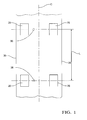
- Figure 1 is a perspective view of the flat strip cut away
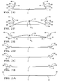
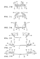
- Figures 2A-M are schematics illustrating the successive steps in a method of fabricating the enclosed tube
- Figure 3 is a fragmentary perspective view partially cut away and in cross section of the enclosed tube.
- Figure 4 is a front view of the heat exchanger assembly partially broken away and in cross section.
- the invention provides a method of fabricating a condenser tube 20 having two ends separated by or defining a pre-determined tube length L and multiple channels 22 each of which having channel sides 24 and channel bottoms 25 extending the length of the condenser tube 20.
- the method comprises the steps of forming at least one aperture 26 in a flat strip 28 of metal at the pre-determined tube length L (shown in Figure 1 ), moving the flat strip 28 of metal through a plurality of forming operations to fold or bend it into an enclosed tube 30 divided into closed channels 22 having channel sides 24 including the aperture 26 (shown in Figures 2A-M ), and severing the enclosed tube 30 across the aperture 26 to separate the enclosed tube 30 into one condenser tube 20 of the pre-determined tube length L without engaging the channel sides 24.
- the severing step is performed successively, each time severing the enclosed tube 30 across the next, successive aperture 26 and between adjacent ends of successive condenser tubes 20 to separate the enclosed tube 30 into a plurality of condenser tubes 20.
- the aperture 26 Upon severing through the aperture 26, the aperture 26 is divided into an open notch 31 in each of the adjacent ends of successive condenser tubes 20.
- the notch 31 in one end of one condenser tube 20 and the notch 31 in the adjacent end of the next condenser tube 20 are both formed from the same aperture 26.
- the preferred embodiment includes multiple channels 22 defining multiple channel sides 24, the invention requires only one longitudinally extending channel side 24 separating the channels 22. It is in this longitudinally extending channel side 24 that the apertures 26, and subsequently the notches 31, are positioned.
- the flat strip 28 of metal has a center line C that bisects the strip along its length, two outer edges 36 opposing one another on opposite sides of the center line C, and a middle portion.
- the flat strip 28 is preferably metal but could be of any material suitable for a condenser tube 20.
- a plurality of pairs of apertures 26 are formed in the flat strip 28. Each of the pairs is spaced from the next pair by a distance equal to the pre-determined tube length L. Each of the pairs straddles the center line C. In other words, there is one aperture 26 on each side of the center line C as the respective pair is aligned transversely of the center line C. Both apertures 26 are equidistant from the center line C.
- the apertures 26 will be formed into the channel sides 24 and channel bottoms 25 as the channels 22 are formed via the forming operations. Alternatively, any number of apertures 26 could be formed and the size, shape, and number of the apertures 26 would depend on the design of the enclosed tube 30.
- a hole 38 is formed in the flat strip 28 between the apertures 26 of each pair of apertures 26.
- the hole 38 will be utilized to error-proof the subsequent severing operation.
- the hole 38 is aligned transversely of the center line C.
- the position of the hole 38 between the apertures 26 of a particular pair on the flat strip 28 is such that the hole 38 will align under one of the apertures 26 in the channel sides 24 and channel bottoms 25 once the forming operations are completed.
- the severing operation employs a severing device. The severing device should cut and sever the enclosed tube 30 across the hole 38 and the apertures 26. If the severing device is not properly aligned, its cut will not pass through the apertures 26, and will consequently damage the channel sides 24.
- the severed condenser tube 20 is installed between two headers 73 to define a heat exchanger, which is then charged with cooling fluid as is known in the art.
- Each header 73 includes a header wall 74 and the condenser tube 20 extends through each header wall 74 of the respective header 73.
- the hole 38 and the notches 31 will be disposed outside of the header wall 74, where the cooling fluid will leak through the notches 31 and the hole 38. As such, the leak would be easily detected.
- the hole 38 must align under one of the apertures 26. Without being under one of the apertures 26, the cooling fluid cannot leak through the otherwise enclosed channel 22 and through the hole 38.
- the first forming operation (after the forming of the apertures 26, shown in Figure 2B , forms a downwardly facing first V shaped groove 40 inward of each outer edge 36.
- Each first V shaped groove 40 has diverging walls that extend along the length of the strip. This forming operation leaves a flat portion 42 of the strip between each first V shaped groove 40 and each adjacent outer edge 36. The flat portion 42 also extends along the length of the strip.
- each flat portion 42 upwardly to form an upwardly facing second V shaped groove 44 immediately adjacent to the respective first V shaped groove 40.
- each second V shaped groove 44 shares a common wall with the respective first V shaped groove 40.
- the outward wall of each first V shaped groove 40 and the inward wall of the respective second V shaped groove 44 are the same wall.
- This forming operation leaves a flange 46 extending from each second V shaped groove 44 to the adjacent outer edge 36.
- Each of the first and second V shaped grooves 40, 44 are then formed into first and second U shaped grooves 48, 50, respectively, as shown in Figure 2D .
- Each first U shaped groove 48 and each second U shaped groove 50 is generally rectangular in shape and has two sides which are substantially parallel to one another.
- Each first and second U shaped groove 48, 50 has a bottom.
- the bottoms of each of the first and second U shaped grooves 48, 50 are formed from the metal that previously formed the apices of the first and second V shaped grooves 40, 44, respectively.
- Each of the bottoms is generally perpendicular to and connects the respective sides and each of the second U shaped grooves 50 shares a common side with the respective first U shaped groove 48.
- the flange 46 extends from each second U shaped groove 50 to the adjacent outer edge 36.
- an upward bow 52 is formed in the middle portion of the flat strip 28 between the first and second U shaped grooves 48, 50 on each side of the center line C as shown in Figure 2E .
- the upward bow 52 has a shallow height H s measured from the horizontal plane to the highest point of the upward bow 52.
- This forming operation also includes moving the two outer edges 36 upwardly to an inclined angle to form a first bend 56.
- the outer edges 36 can be angled further upwardly. Without bowing the middle portion, the tooling could not achieve the inclined angle.
- Each first bend 56 is spaced inwardly from the respective first U shaped groove 48 by a third groove bottom piece 58. When the forming operations are complete, each of these third groove bottom pieces 58 will define the bottom of an additional third groove 60.
- the next forming operation increases the height of the upward bow 52 to define a deep height H d , which is taller than the shallow height H s .
- This forming operation also includes moving the two outer edges 36 upwardly from the previous inclined angle to a position just short of vertical to form a second bend 64.
- Each second bend 64 is spaced inwardly from the respective third groove bottom piece 58 by a third groove side piece 66.
- each of these third groove side pieces 66 will be substantially perpendicular to the respective third groove bottom piece 58 and will define the outward side of the third groove 60.
- the next forming operation forms a downward bow 68 in the middle portion.
- This forming operation also moves the two outer edges 36 inwardly and downwardly toward one another and toward the middle portion of the flat strip 28.
- the outer edges 36 can be angled further inwardly and downwardly. Without bowing the middle portion, the tooling could not achieve the desired angle.
- the next forming operation shown in Figure 2I , straightens the downwardly bowed middle portion of the strip and moves the flanges 46 and the bottoms of the first U shaped grooves 48 downwardly to engage them with the middle portion.
- the second U shaped grooves 50 and the third grooves 60 are closed and define channels 22.
- One channel 22 is formed by each second U shaped groove 50 with the sides of each second U shaped groove 50 becoming the channel sides 24 of the respective channel 22. Additionally, the bottoms of the second U shaped grooves 50 become the channel bottoms 25 of each of the respective channels 22.
- Another channel 22 is formed by each third groove side piece 66, the respective third groove bottom piece 58, and the adjacent wall of the respective first U shaped groove 48.
- the third groove bottom pieces 58 and the wall of the respective first U shaped groove 48 become the channel sides 24 and the third groove bottom pieces 58 become the channel bottoms 25 of each of these channels 22.
- These channels 22 are rectangular in cross section and extend the length of the strip.
- the first U shaped grooves 48 which were initially downwardly facing, now face upwardly and share channel sides 24 with the channels 22 defined by each second U shaped groove 50 and the respective third groove 60 on each side of the center line C.
- the next forming operation forms a third bend 70 inward of each of the flanges 46 and moves the bottoms of the second and third grooves 60 rotationally and into engagement with the remaining middle portion.
- the first U shaped grooves 48 are closed and define channels 22.
- One channel 22 is formed by each first U shaped groove 48 with the sides of each first U shaped groove 48 becoming the channel sides 24 of the respective channel 22 and the bottoms of each first U shaped groove 48 becoming the channel bottoms 25 of each of the respective channels 22.
- These channels 22 are rectangular in cross section and extend the length of the strip.
- Two additional channels 22 are defined as the bottoms of the second and third grooves 60 are rotated.
- These channels 22 are positioned outwardly of each of the second U shaped grooves 50 and inwardly of the adjacent third bend 70. Each of the respective outer sides of these channels 22 is rounded.
- the outward sides of the third grooves 60 abut and thereby enclose all of the channels 22 to produce a continuous enclosed tube 30 having eight channels 22 extending the length of the enclosed tube 30.
- the continuous enclosed tube 30 is then severed, as by the blade 72, transversely across its width and across the apertures 26 to separate the continuous enclosed tube 30 into one condenser tube 20 of the pre-determined tube length L, as shown in Figure 3 .
- the apertures 26 extend transversely of the center line C and between the respective flange 46 and the respective abutted side of the third groove 60 of the enclosed tube 30.
- the severing is accomplished by moving the severing device across the enclosed tube 30.
- the recommended severing device is a blade 72. Once the cut is made, the blade 72 returns to its original position, where it remains until the next pair of apertures 26 is aligned into position. Successive severing operations yield successive condenser tubes 20. Because each pair of apertures 26 is spaced from the next pair by the pre-determined tube length L, each severing operation produces a condenser tube 20 of the pre-determined tube length L.
- the apertures 26 in the channel sides 24 eliminate the need for the channel sides 24 to be severed, particularly from a broadside. As such, these portions of the channel sides 24 do not come in contact with the blade 72. Because no contact is made, there is no opportunity for the channel sides 24 to become contaminated, distorted, or otherwise damaged. The portion of the flat strip 28 that encloses the channels 22 still must be severed, however.
- the invention includes a heat exchanger assembly, shown in Figure 4 , comprising two headers 73 each of which headers 73 includes a header wall 74 with the header walls 74 spaced from and facing one another and the condenser tube 20 produced via the method.
- the condenser tube 20 extends between the headers 73 and through the header walls 74 and conveys cooling fluid through the header walls 74 and into the headers 73.
- the cooling fluid flows through the condenser tube 20, which has multiple channels 22 extending therethrough, and collects in each of the headers 73.
- a plurality of fins extends between adjacent condenser tubes 20 for transferring heat from the condenser tubes 20 to air passing through the heat exchanger to ultimately cool the fluid in the condenser tubes 20.
- the condenser tube 20 has a center line C and two ends separated by the pre-determined tube length L.
- the center line C of the condenser tube 20 and the center line C of the flat strip 28 are the same center line C.
- the condenser tube 20 has a flat cross section with a pair of parallel and spaced tube walls 76 extending between rounded edges 78.
- the condenser tube 20 includes the plurality of U shaped channels 22 formed during the forming operations of the method. These channels 22 extend between the ends with each of the channels 22 having two parallel channel sides 24 and a channel bottom 25 perpendicular to and connecting said two channel sides 24 to form the U shape.
- U shaped channels 22 are disposed on each side of the center line C with one downwardly facing U shaped channel 22 sharing channel sides 24 with two upwardly facing U shaped channels 22. As mentioned above, these channels 22, including the respective channel sides 24 and channel bottoms 25, are formed and positioned during the forming operations of the method of the invention.
- the condenser tube 20 extends through a bend outwardly of each of said flanges 46. This bend defines the rounded edges 78 on each side of the condenser tube 20 and the bend defines two edge channels 22 extending along the length of the condenser tube 20.
- Each of the upwardly facing U shaped channels 22 disposed next adjacent to the center line C has channel sides 24 abutting one another along the center line C.
- the two innermost U shaped channels 22 face upwardly and abut one another as they extend along the center line C.
- Immediately outward of each of these two upwardly facing U shaped channels 22 is one downwardly facing U shaped channel 22.
- One additional upwardly facing U shaped channel 22 is disposed immediately outwardly of each of the downwardly facing U shaped channels 22 and one edge channel 22 is disposed immediately outwardly of each of the outermost upwardly facing U shaped channels 22.
- the number, shape, and disposition of the channels 22 could vary as is known in the art.
- the invention requires that there be at least one channel side 24 separating two channels 22.
- a flange 46 extends generally horizontally from each of the upwardly facing U shaped channels 22 disposed most outwardly on each side of the center line C.
- Each of the U shaped channels 22 includes the open notch 31 in the channel sides 24.
- the notch 31 extends transversely of the center line C from each of the flanges 46 to the respective abutting channel sides 24.
- the notch 31 is disposed adjacent each of the condenser tube 20 ends.
- the notches 31 are a result of the enclosed tube 30 being severed across the apertures 26. It is the utilization of these apertures 26 in the severing step that prevents damage to the channel 22 walls that would be otherwise done by the blade 72 used to sever the condenser tube 20 to the pre-determined tube length L.
- the tube also defines a hole 38 disposed transversely of the center line C.
- the hole 38 is aligned on each of the condenser tube 20 ends and under one of the apertures 26.
- the hole 38 is used to verify that the notches 31 are disposed within the header walls 74.
- a leak therethrough has no effect on the operation of the heat exchanger.
- cooling fluid would leak through the aperture 26 and the hole 38 and would be easily detected. As mentioned above, this leak would signify that the condenser tube 20 was not severed across the respective apertures 26.
Landscapes
- Engineering & Computer Science (AREA)
- Mechanical Engineering (AREA)
- Physics & Mathematics (AREA)
- Thermal Sciences (AREA)
- General Engineering & Computer Science (AREA)
- Geometry (AREA)
- Heat-Exchange Devices With Radiators And Conduit Assemblies (AREA)
- Air Bags (AREA)
- Vaporization, Distillation, Condensation, Sublimation, And Cold Traps (AREA)
- Folding Of Thin Sheet-Like Materials, Special Discharging Devices, And Others (AREA)
Abstract
Description
- The present invention relates to a condenser tube for use in a heat exchanger.
- Heat exchangers normally include a pair of tanks or headers and a plurality of condenser tubes. The headers include header walls which are spaced from and face one another. The condenser tubes extend between the headers and convey cooling fluid through the header walls and into the closed headers. A plurality of fins extend between adjacent condenser tubes for transferring heat from the tubes to air passing through the heat exchanger to ultimately cool the fluid in the tubes. Such condenser tubes are frequently separated into a plurality of channels.
- A method of forming a flat strip into such a condenser tube having two ends separated by a pre-determined tube length and two channels extending between the ends is disclosed in the
U.S. Patent 6,615,488 to Anders et al . The flat strip is progressively formed via a series of roller stations until the edges are folded into a pair of central abutting flanges engaging the inner surface of the strip along the center. The result is a continuous enclosed B-shaped tube with two channels extending the length of the tube and with the central abutting flanges forming channel sides which separate the channels from one another. The B-shaped tube is then severed to separate it into successive condenser tubes each of the pre-determined tube length. - It is also well known to produce such a condenser tube but having additional channels extending between the ends. The method includes moving the strip through a plurality of forming operations to form a continuous enclosed tube separated into channels by the longitudinally parallel channel sides and severing the enclosed tube to separate the enclosed tube into successive condenser tubes of the pre-determined tube length. Typical severing operations include sawing and die cutting.
- In sawing, cutting residue contaminants, such as metal shavings or particles or cutting lubricants, penetrate the openings and either plug or otherwise contaminate the severed sides of the channels. Because of the small size of the individual channels, it is difficult to remove these contaminants.
- In a die cutting operation, the blade of the die is moved across and through the entire enclosed tube to sever the exterior of the tube as well as the channel sides. Even with a new die and a sharp blade, some distortion of the channel sides occurs. As the blade dulls, the degree of the distortion increases and the severed edges of the individual condenser tubes become severely distorted.
- Whichever severing technique is utilized, undesirable distortion and/or contamination occurs.
- Accordingly, the invention provides such a heat exchanger utilizing the multi-channel condenser tube of the aforementioned type and a method of fabricating same by forming at least one aperture in the flat strip at the pre-determined tube length and positioning the aperture in the channel side separating the channels during the forming of the enclosed tube. The severing operation is further defined as severing the enclosed tube across the aperture without engaging the channel side for separating the enclosed tube into successive condenser tubes of the pre-determined tube length between tube ends with the aperture being divided into a notch in adjacent ends of successive condenser tubes.
- By severing the enclosed tube across the aperture, the deformation and/or contamination of the ends of the condenser tube is eliminated because there is no severing contact with the channel side. When the condenser tube is installed in the heat exchanger, the notches are disposed within the header walls where they have no effect on the operation of the heat exchanger.
- Other advantages of the present invention will be readily appreciated, as the same becomes better understood by reference to the following detailed description when considered in connection with the accompanying drawings wherein:
-
Figure 1 is a perspective view of the flat strip cut away; -
Figures 2A-M are schematics illustrating the successive steps in a method of fabricating the enclosed tube; -
Figure 3 is a fragmentary perspective view partially cut away and in cross section of the enclosed tube; and -
Figure 4 is a front view of the heat exchanger assembly partially broken away and in cross section. - Referring to the Figures, wherein like numerals indicate corresponding parts throughout the several views, the invention provides a method of fabricating a
condenser tube 20 having two ends separated by or defining a pre-determined tube length L andmultiple channels 22 each of which havingchannel sides 24 andchannel bottoms 25 extending the length of thecondenser tube 20. The method comprises the steps of forming at least oneaperture 26 in a flat strip 28 of metal at the pre-determined tube length L (shown inFigure 1 ), moving the flat strip 28 of metal through a plurality of forming operations to fold or bend it into an enclosedtube 30 divided into closedchannels 22 havingchannel sides 24 including the aperture 26 (shown inFigures 2A-M ), and severing the enclosedtube 30 across theaperture 26 to separate the enclosedtube 30 into onecondenser tube 20 of the pre-determined tube length L without engaging thechannel sides 24. The severing step is performed successively, each time severing the enclosedtube 30 across the next,successive aperture 26 and between adjacent ends ofsuccessive condenser tubes 20 to separate the enclosedtube 30 into a plurality ofcondenser tubes 20. Upon severing through theaperture 26, theaperture 26 is divided into anopen notch 31 in each of the adjacent ends ofsuccessive condenser tubes 20. In other words, thenotch 31 in one end of onecondenser tube 20 and thenotch 31 in the adjacent end of thenext condenser tube 20 are both formed from thesame aperture 26. - Although the preferred embodiment includes
multiple channels 22 definingmultiple channel sides 24, the invention requires only one longitudinally extendingchannel side 24 separating thechannels 22. It is in this longitudinally extendingchannel side 24 that theapertures 26, and subsequently thenotches 31, are positioned. - The flat strip 28 of metal has a center line C that bisects the strip along its length, two
outer edges 36 opposing one another on opposite sides of the center line C, and a middle portion. The flat strip 28 is preferably metal but could be of any material suitable for acondenser tube 20. - A plurality of pairs of
apertures 26 are formed in the flat strip 28. Each of the pairs is spaced from the next pair by a distance equal to the pre-determined tube length L. Each of the pairs straddles the center line C. In other words, there is oneaperture 26 on each side of the center line C as the respective pair is aligned transversely of the center line C. Bothapertures 26 are equidistant from the center line C. Theapertures 26 will be formed into thechannel sides 24 andchannel bottoms 25 as thechannels 22 are formed via the forming operations. Alternatively, any number ofapertures 26 could be formed and the size, shape, and number of theapertures 26 would depend on the design of the enclosedtube 30. - A
hole 38 is formed in the flat strip 28 between theapertures 26 of each pair ofapertures 26. Thehole 38 will be utilized to error-proof the subsequent severing operation. Thehole 38 is aligned transversely of the center line C. The position of thehole 38 between theapertures 26 of a particular pair on the flat strip 28 is such that thehole 38 will align under one of theapertures 26 in thechannel sides 24 andchannel bottoms 25 once the forming operations are completed. The severing operation employs a severing device. The severing device should cut and sever the enclosedtube 30 across thehole 38 and theapertures 26. If the severing device is not properly aligned, its cut will not pass through theapertures 26, and will consequently damage thechannel sides 24. - The severed
condenser tube 20 is installed between twoheaders 73 to define a heat exchanger, which is then charged with cooling fluid as is known in the art. Eachheader 73 includes aheader wall 74 and thecondenser tube 20 extends through eachheader wall 74 of therespective header 73. As the heat exchanger is operated, it is checked for leakage of cooling fluid through thehole 38. If the severing device was aligned properly and thecondenser tube 20 was cut across theapertures 26, thehole 38 and thenotches 31 will be disposed within therespective header wall 74, where a leak would have no effect on the operation of the heat exchanger. However, if the severing device was not properly aligned and thecondenser tube 20 was not cut across theapertures 26, thehole 38 and thenotches 31 will be disposed outside of theheader wall 74, where the cooling fluid will leak through thenotches 31 and thehole 38. As such, the leak would be easily detected. - For this error-proofing mechanism to function properly, the
hole 38 must align under one of theapertures 26. Without being under one of theapertures 26, the cooling fluid cannot leak through the otherwise enclosedchannel 22 and through thehole 38. - The first forming operation (after the forming of the
apertures 26, shown inFigure 2B , forms a downwardly facing first Vshaped groove 40 inward of eachouter edge 36. Each first V shapedgroove 40 has diverging walls that extend along the length of the strip. This forming operation leaves aflat portion 42 of the strip between each first V shapedgroove 40 and each adjacentouter edge 36. Theflat portion 42 also extends along the length of the strip. - The next forming operation, shown in
Figure 2C , forms eachflat portion 42 upwardly to form an upwardly facing second Vshaped groove 44 immediately adjacent to the respective first V shapedgroove 40. As such, each second V shapedgroove 44 shares a common wall with the respective first V shapedgroove 40. In other words, the outward wall of each first V shapedgroove 40 and the inward wall of the respective second V shapedgroove 44 are the same wall. This forming operation leaves aflange 46 extending from each second V shapedgroove 44 to the adjacentouter edge 36. - Each of the first and second V shaped
grooves grooves Figure 2D . Each first U shapedgroove 48 and each second U shapedgroove 50 is generally rectangular in shape and has two sides which are substantially parallel to one another. Each first and second U shapedgroove grooves grooves grooves 50 shares a common side with the respective first U shapedgroove 48. Theflange 46 extends from each second U shapedgroove 50 to the adjacentouter edge 36. - Next, an
upward bow 52 is formed in the middle portion of the flat strip 28 between the first and second U shapedgrooves Figure 2E . Theupward bow 52 has a shallow height Hs measured from the horizontal plane to the highest point of theupward bow 52. This forming operation also includes moving the twoouter edges 36 upwardly to an inclined angle to form afirst bend 56. By forming theupward bow 52, theouter edges 36 can be angled further upwardly. Without bowing the middle portion, the tooling could not achieve the inclined angle. Eachfirst bend 56 is spaced inwardly from the respective first U shapedgroove 48 by a thirdgroove bottom piece 58. When the forming operations are complete, each of these thirdgroove bottom pieces 58 will define the bottom of an additionalthird groove 60. - The next forming operation, shown in
Figure 2F , increases the height of theupward bow 52 to define a deep height Hd, which is taller than the shallow height Hs. This forming operation also includes moving the twoouter edges 36 upwardly from the previous inclined angle to a position just short of vertical to form asecond bend 64. Eachsecond bend 64 is spaced inwardly from the respective thirdgroove bottom piece 58 by a thirdgroove side piece 66. When the forming operations are complete, each of these thirdgroove side pieces 66 will be substantially perpendicular to the respective thirdgroove bottom piece 58 and will define the outward side of thethird groove 60. - The next forming operation, shown in
Figure 2G , straightens the upwardly bowed middle portion. In doing so, each of the twoouter edges 36 are rotated inwardly to an angle slightly past vertical. - The next forming operation, shown in
Figure 2H , forms adownward bow 68 in the middle portion. This forming operation also moves the twoouter edges 36 inwardly and downwardly toward one another and toward the middle portion of the flat strip 28. By forming thedownward bow 68, theouter edges 36 can be angled further inwardly and downwardly. Without bowing the middle portion, the tooling could not achieve the desired angle. - The next forming operation, shown in
Figure 2I , straightens the downwardly bowed middle portion of the strip and moves theflanges 46 and the bottoms of the first U shapedgrooves 48 downwardly to engage them with the middle portion. In doing so, the second U shapedgrooves 50 and thethird grooves 60 are closed and definechannels 22. Onechannel 22 is formed by each second U shapedgroove 50 with the sides of each second U shapedgroove 50 becoming the channel sides 24 of therespective channel 22. Additionally, the bottoms of the second U shapedgrooves 50 become thechannel bottoms 25 of each of therespective channels 22. Anotherchannel 22 is formed by each thirdgroove side piece 66, the respective thirdgroove bottom piece 58, and the adjacent wall of the respective first U shapedgroove 48. The thirdgroove bottom pieces 58 and the wall of the respective first U shapedgroove 48 become the channel sides 24 and the thirdgroove bottom pieces 58 become thechannel bottoms 25 of each of thesechannels 22. Thesechannels 22 are rectangular in cross section and extend the length of the strip. The first U shapedgrooves 48, which were initially downwardly facing, now face upwardly and share channel sides 24 with thechannels 22 defined by each second U shapedgroove 50 and the respectivethird groove 60 on each side of the center line C. - The next forming operation, shown in
Figure 2J , forms athird bend 70 inward of each of theflanges 46 and moves the bottoms of the second andthird grooves 60 rotationally and into engagement with the remaining middle portion. In doing so, the first U shapedgrooves 48 are closed and definechannels 22. Onechannel 22 is formed by each first U shapedgroove 48 with the sides of each first U shapedgroove 48 becoming the channel sides 24 of therespective channel 22 and the bottoms of each first U shapedgroove 48 becoming thechannel bottoms 25 of each of therespective channels 22. Thesechannels 22 are rectangular in cross section and extend the length of the strip. Twoadditional channels 22 are defined as the bottoms of the second andthird grooves 60 are rotated. Thesechannels 22 are positioned outwardly of each of the second U shapedgrooves 50 and inwardly of the adjacentthird bend 70. Each of the respective outer sides of thesechannels 22 is rounded. By rotationally moving the bottoms of the second and third U shapedgrooves Figures 2K, 2L, and 2M , the outward sides of thethird grooves 60 abut and thereby enclose all of thechannels 22 to produce a continuousenclosed tube 30 having eightchannels 22 extending the length of theenclosed tube 30. - The continuous
enclosed tube 30 is then severed, as by theblade 72, transversely across its width and across theapertures 26 to separate the continuousenclosed tube 30 into onecondenser tube 20 of the pre-determined tube length L, as shown inFigure 3 . After the forming operations are completed, theapertures 26 extend transversely of the center line C and between therespective flange 46 and the respective abutted side of thethird groove 60 of theenclosed tube 30. By severing theenclosed tube 30 across theseapertures 26, the channel sides 24 are not engaged, and hence not distorted or otherwise damaged. - The severing is accomplished by moving the severing device across the
enclosed tube 30. The recommended severing device is ablade 72. Once the cut is made, theblade 72 returns to its original position, where it remains until the next pair ofapertures 26 is aligned into position. Successive severing operations yieldsuccessive condenser tubes 20. Because each pair ofapertures 26 is spaced from the next pair by the pre-determined tube length L, each severing operation produces acondenser tube 20 of the pre-determined tube length L. - The
apertures 26 in the channel sides 24 eliminate the need for the channel sides 24 to be severed, particularly from a broadside. As such, these portions of the channel sides 24 do not come in contact with theblade 72. Because no contact is made, there is no opportunity for the channel sides 24 to become contaminated, distorted, or otherwise damaged. The portion of the flat strip 28 that encloses thechannels 22 still must be severed, however. - In addition to the method of the invention, the invention includes a heat exchanger assembly, shown in
Figure 4 , comprising twoheaders 73 each of whichheaders 73 includes aheader wall 74 with theheader walls 74 spaced from and facing one another and thecondenser tube 20 produced via the method. Thecondenser tube 20 extends between theheaders 73 and through theheader walls 74 and conveys cooling fluid through theheader walls 74 and into theheaders 73. The cooling fluid flows through thecondenser tube 20, which hasmultiple channels 22 extending therethrough, and collects in each of theheaders 73. A plurality of fins extends betweenadjacent condenser tubes 20 for transferring heat from thecondenser tubes 20 to air passing through the heat exchanger to ultimately cool the fluid in thecondenser tubes 20. - The
condenser tube 20 has a center line C and two ends separated by the pre-determined tube length L. The center line C of thecondenser tube 20 and the center line C of the flat strip 28 are the same center line C. Thecondenser tube 20 has a flat cross section with a pair of parallel and spacedtube walls 76 extending between rounded edges 78. Thecondenser tube 20 includes the plurality of U shapedchannels 22 formed during the forming operations of the method. Thesechannels 22 extend between the ends with each of thechannels 22 having two parallel channel sides 24 and a channel bottom 25 perpendicular to and connecting said twochannel sides 24 to form the U shape. Three U shapedchannels 22 are disposed on each side of the center line C with one downwardly facing U shapedchannel 22sharing channel sides 24 with two upwardly facing U shapedchannels 22. As mentioned above, thesechannels 22, including therespective channel sides 24 andchannel bottoms 25, are formed and positioned during the forming operations of the method of the invention. Thecondenser tube 20 extends through a bend outwardly of each of saidflanges 46. This bend defines therounded edges 78 on each side of thecondenser tube 20 and the bend defines twoedge channels 22 extending along the length of thecondenser tube 20. - Each of the upwardly facing U shaped
channels 22 disposed next adjacent to the center line C haschannel sides 24 abutting one another along the center line C. In other words, the two innermost U shapedchannels 22 face upwardly and abut one another as they extend along the center line C. Immediately outward of each of these two upwardly facing U shapedchannels 22 is one downwardly facing U shapedchannel 22. One additional upwardly facing U shapedchannel 22 is disposed immediately outwardly of each of the downwardly facing U shapedchannels 22 and oneedge channel 22 is disposed immediately outwardly of each of the outermost upwardly facing U shapedchannels 22. - Alternatively, the number, shape, and disposition of the
channels 22 could vary as is known in the art. However, the invention requires that there be at least onechannel side 24 separating twochannels 22. - A
flange 46 extends generally horizontally from each of the upwardly facing U shapedchannels 22 disposed most outwardly on each side of the center line C. - Each of the U shaped
channels 22 includes theopen notch 31 in the channel sides 24. Thenotch 31 extends transversely of the center line C from each of theflanges 46 to the respective abutting channel sides 24. Thenotch 31 is disposed adjacent each of thecondenser tube 20 ends. As mentioned above, thenotches 31 are a result of theenclosed tube 30 being severed across theapertures 26. It is the utilization of theseapertures 26 in the severing step that prevents damage to thechannel 22 walls that would be otherwise done by theblade 72 used to sever thecondenser tube 20 to the pre-determined tube length L. - The tube also defines a
hole 38 disposed transversely of the center line C. Thehole 38 is aligned on each of thecondenser tube 20 ends and under one of theapertures 26. Thehole 38 is used to verify that thenotches 31 are disposed within theheader walls 74. When thehole 38 is disposed within theheader walls 74, a leak therethrough has no effect on the operation of the heat exchanger. However, if thehole 38 were to be disposed outside of theheader walls 74, cooling fluid would leak through theaperture 26 and thehole 38 and would be easily detected. As mentioned above, this leak would signify that thecondenser tube 20 was not severed across therespective apertures 26. - While the invention has been described with reference to an exemplary embodiment, it will be understood by those skilled in the art that various changes may be made and equivalents may be substituted for elements thereof without departing from the scope of the invention. In addition, many modifications may be made to adapt a particular situation or material to the teachings of the invention without departing from the essential scope thereof. Therefore, it is intended that the invention not be limited to the particular embodiment disclosed as the best mode contemplated for carrying out this invention, but that the invention will include all embodiments falling within the scope of the appended claims.
Claims (25)
- A method for fabricating a condenser tube having two ends separated by a pre-determined tube length and multiple channels extending the length of the tube comprising the steps of;
moving a flat strip of metal having a center line and a middle portion and outer edges extending along the strip through a plurality of forming operations and forming an enclosed tube separated into channels by at least one longitudinally extending side, severing the enclosed tube for separating the enclosed tube into successive condenser tubes each of the pre-determined length between the ends thereof,
forming at least one aperture in the flat strip at the pre-determined tube length and positioning the aperture in the side separating the channels during the forming of the enclosed tube, and
wherein said severing is further defined as severing the enclosed tube across the aperture without engaging the side of the channels for separating the enclosed tube into successive condenser tubes of the pre-determined tube length between the ends with the aperture divided into a notch in adjacent ends of successive condenser tubes. - A method as set forth in claim 1 including forming a hole in the flat strip aligned transversely of the center line and from the aperture to be disposed under the aperture during the forming of the enclosed tube.
- A method as set forth in claim 2 including installing the condenser tube between two headers to define a heat exchanger.
- A method as set forth in claim 3 including charging the heat exchanger with cooling fluid and checking for leakage of cooling fluid from the hole to verify that the hole and notches are disposed within the headers.
- A method as set forth in claim 1 wherein the enclosed tube is separated into channels by a plurality of longitudinally extending sides.
- A method as set forth in claim 5 wherein said forming at least one aperture is further defined as forming a pair of rectangular apertures straddling the center line at the pre-determined tube length for defining notches in the sides of the channels.
- A method as set forth in claim 6 wherein said forming is further defined as forming on each outer edge of the flat strip an upwardly facing first U shaped groove defining the sides and having a bottom extending along the strip and a flange outward of the first U shaped groove, and moving the first U shaped grooves into engagement with the middle portion of the strip to close each of the first U shaped grooves to define a channel on each side of the center line.
- A method as set forth in claim 7 wherein said forming is further defined as including moving the bottoms of the channels into engagement with the remaining middle portion to abut the outward sides of each of the first U shaped grooves to one another and to define a channel positioned outwardly of each of the first U shaped grooves to produce an enclosed tube having multiple channels extending the length of the enclosed tube.
- A method as set forth in claim 8 wherein the apertures of each pair are aligned transversely of the center line and extend transversely of the center line between the flanges and the abutting outward sides of each of the U shaped grooves to define notches in the sides of the channels.
- A method for fabricating a condenser tube having a pre-determined tube length and multiple channels extending the length of the tube comprising the steps of;
moving a flat strip of metal having a center line and outer edges extending the length of the strip through a plurality of forming operations,
forming a downwardly facing first V shaped groove extending the length of the strip and positioned inwardly of each outer edge of the strip leaving a flat portion of the strip between each first V shaped groove and each adjacent outer edge,
forming an upwardly facing second V shaped groove in the flat portion and a flange extending to the adjacent outer edge,
forming the first and second V shaped grooves into first and second U shaped grooves having first and second groove bottoms and sides,
forming an upward bow having a shallow height in the middle portion of the strip between the grooves along the respective edges and moving the two outer edges upwardly to an inclined angle to form a first bend spaced inwardly from the first U-shaped groove the width of a bottom of a third groove,
increasing the height of the upward bow to define a deep height and moving the two outer edges upwardly from the inclined angle to a position just short of vertical to form a second bend spaced inwardly from the width of the bottom to define a third groove side extending along the strip,
straightening the upwardly bowed middle portion to rotate the two outer edges inwardly past vertical,
forming a downward bow in the middle portion and moving the two outer edges inwardly and downwardly toward one another and toward the middle portion,
straightening the downwardly bowed middle portion of the strip and moving the flanges and the bottoms of the first U shaped grooves downwardly and into engagement with the middle portion to close the second and third U shaped grooves to define respective channels and leaving the first U shaped groove opening upwardly between the second and third U shaped grooves,
forming a third bend inwardly of each of the flanges and moving the bottoms of the second and third U shaped grooves into engagement with the middle portion to close the first U shaped grooves to define a channel and to abut the sides of the third grooves to define a channel positioned outwardly of each of the second U shaped grooves and inwardly of each third bend to produce an enclosed tube having eight channels extending the length of the enclosed tube,
severing the enclosed tube for separating the enclosed tube into successive condenser tubes each of the pre-determined length, and
forming a plurality of pairs of rectangular apertures in the flat strip with each of the pairs straddling the center line at the pre-determined tube lengths and aligned transversely of the center line and extending transversely of the center line between the flanges and the abutting sides of the third grooves and disposing the aperture in the sides separating the channels during the forming of the enclosed tube, and
wherein said severing is further defined as severing the enclosed tube across the apertures without engaging the sides of the channels for separating the enclosed tube into successive condenser tubes of the pre-determined tube length between ends with the aperture divided into a notch in adjacent ends of successive condenser tubes. - A method as set forth in claim 10 including the steps of;
forming a hole in the flat strip aligned transversely of the center line and between the apertures to be disposed under the apertures during the forming of the enclosed tube,
installing the condenser tube between two headers to define a heat exchanger,
charging the heat exchanger with cooling fluid, and
checking for leakage of cooling fluid from the hole to verify that the hole and the notches are disposed within the headers to verify that the condenser tube was severed across the apertures. - A heat exchanger assembly for cooling comprising;
two headers each including a header wall with said header walls spaced from and facing each other,
a condenser tube extending between and through said header walls for conveying cooling fluid between said headers and having a center line and two ends separated by a pre-determined tube length and a plurality of channels extending between said ends with said channels being separated by at least one longitudinally extending channel side, and
said channel side defining a notch disposed adjacent each of said condenser tube ends. - An assembly as set forth in claim 12
wherein said tube defines a hole disposed transversely of said center line and aligned under said aperture at each of said condenser tube ends and disposed within said header walls for verifying that said notches are disposed within said headers. - An assembly as set forth in claim 12 wherein each of said channels is U shaped and includes two parallel channel sides and a channel bottom perpendicular to and connecting said two channel sides.
- An assembly as set forth in claim 14 wherein at least one U shaped channel is disposed on each side of said center line with each of said U shaped channels disposed next adjacent to said center line and having said channel sides abutting one another along said center line.
- An assembly as set forth in claim 15 wherein said tube has a cross section including a flange extending generally horizontally from each of the U shaped channels disposed most outwardly on each side of said center line.
- An assembly as set forth in claim 16 wherein said notches are disposed adjacent said condenser tube ends and within said header walls and extend transversely of said center line from each said flange to said respective abutting U shaped channel sides.
- An assembly as set forth in claim 14 wherein three of said U shaped channels are disposed on each side of said center line with one downwardly facing U shaped channel sharing channel sides with two upwardly facing U shaped channels.
- An assembly as set forth in claim 18 wherein said tube has a cross section including a flange extending generally horizontally from each of the upwardly facing U shaped channels disposed most outwardly on each side of said center line.
- An assembly as set forth in claim 19 wherein each of said upwardly facing U shaped channels disposed next adjacent to said center line has said channel sides abutting one another along said center line.
- An assembly as set forth in claim 12 wherein said tube has a flat cross section with a pair of parallel and spaced walls extending between rounded edges.
- An assembly as set forth in claim 21 wherein said tube has a cross section including a bend outwardly of each of said flanges defining said rounded edges and enclosing edge channels extending along said tube to define a totally enclosed tube having six of said enclosed U shaped channels and two of said edge channels extending the length of said enclosed tube.
- An assembly as set forth in claim 22 wherein said notches are disposed adjacent said condenser tube ends and within said header walls and extend transversely of said center line from each said flange to said respective abutting U shaped channel side.
- A heat exchanger assembly for cooling comprising;
two headers each including a header wall with said header walls spaced from and facing each other,
a condenser tube extending between and through said header walls for conveying cooling fluid between said headers,
said condenser tube having a center line and two ends separated by a pre-determined tube length and a flat cross section with a pair of parallel and spaced walls extending between rounded edges,
said tube cross section including a plurality of U shaped channels extending between said ends of said condenser tube with each of said channels having two parallel channel sides and a channel bottom perpendicular to and connecting said two channel sides,
three of said U shaped channels disposed on each side of said center line with one downwardly facing U shaped channel sharing channel sides with two upwardly facing U shaped channels,
said tube cross section including a flange extending generally horizontally from each of the upwardly facing U shaped channels disposed most outwardly on each side of said center line,
each of said upwardly facing U shaped channels disposed next adjacent to said center line having said channel sides abutting one another along said center line,
said tube cross section including a bend outwardly of each of said flanges and defining said rounded edges and enclosing edge channels extending along said tube to define a totally enclosed tube having six of said enclosed U shaped channels and two of said edge channels extending the length of said enclosed tube, and
said U shaped channels defining a notch in each of said U shaped channel sides disposed adjacent said condenser tube ends and within said header walls and extending transversely of said center line from each of said flanges to said respective abutting U shaped channel sides. - An assembly as set forth in claim 24 wherein said tube defines a hole disposed transversely of said center line and aligned under one of said apertures at each of said condenser tube ends and disposed within said header walls for verifying that said notches are disposed within said headers.
Applications Claiming Priority (1)
| Application Number | Priority Date | Filing Date | Title |
|---|---|---|---|
| US11/649,610 US7657986B2 (en) | 2007-01-04 | 2007-01-04 | Method of making a folded condenser tube |
Publications (2)
| Publication Number | Publication Date |
|---|---|
| EP1941954A1 true EP1941954A1 (en) | 2008-07-09 |
| EP1941954B1 EP1941954B1 (en) | 2010-04-14 |
Family
ID=39103485
Family Applications (1)
| Application Number | Title | Priority Date | Filing Date |
|---|---|---|---|
| EP07122362A Active EP1941954B1 (en) | 2007-01-04 | 2007-12-05 | Method of manufacturing a B-shaped folded condenser tube |
Country Status (4)
| Country | Link |
|---|---|
| US (1) | US7657986B2 (en) |
| EP (1) | EP1941954B1 (en) |
| AT (1) | ATE464133T1 (en) |
| DE (1) | DE602007005918D1 (en) |
Cited By (6)
| Publication number | Priority date | Publication date | Assignee | Title |
|---|---|---|---|---|
| WO2012106242A2 (en) | 2011-01-31 | 2012-08-09 | Delphi Technologies, Inc. | Method of fabricating a double-nosed tube for a heat exchanger |
| JP2015134376A (en) * | 2014-01-17 | 2015-07-27 | シャンハイ ジャオ トン ユニバーシティ | Microchannel flat tube roll forming machine and forming method |
| EP3096102A1 (en) | 2015-05-22 | 2016-11-23 | Delphi Automotive Systems Luxembourg SA | Flat tube for a heat exchanger |
| EP3108980A1 (en) * | 2015-06-09 | 2016-12-28 | Mahle International GmbH | Method of fabricating a tube for an evaporator and device for fabricating a tube for an evaporator |
| EP2388545A3 (en) * | 2010-05-20 | 2018-03-21 | MAHLE International GmbH | Folded tube for an evaporator and evaporator assembly therewith |
| DE102020207067A1 (en) | 2020-06-05 | 2021-12-09 | Mahle International Gmbh | Flat tube and heat exchanger with a flat tube |
Families Citing this family (10)
| Publication number | Priority date | Publication date | Assignee | Title |
|---|---|---|---|---|
| US20150360333A1 (en) * | 2010-05-20 | 2015-12-17 | Mahle International Gmbh | Method of fabricating a tube for an evaporator |
| US8661676B2 (en) | 2011-03-29 | 2014-03-04 | Frank G. McNulty | Rotary die forming process and apparatus for fabricating multi-port tubes |
| JP2013072607A (en) * | 2011-09-28 | 2013-04-22 | Keihin Thermal Technology Corp | Method of manufacturing heat exchanger |
| US9266092B2 (en) | 2013-01-24 | 2016-02-23 | Basf Corporation | Automotive catalyst composites having a two-metal layer |
| US20150211807A1 (en) * | 2014-01-29 | 2015-07-30 | Trane International Inc. | Heat Exchanger with Fluted Fin |
| WO2017116845A1 (en) * | 2015-12-28 | 2017-07-06 | Carrier Corporation | Folded conduit for heat exchanger applications |
| US12050067B2 (en) | 2018-12-19 | 2024-07-30 | Carrier Corporation | Heat exchanger with aluminum alloy clad tube and method of manufacture |
| US20230138731A1 (en) | 2021-11-02 | 2023-05-04 | Carrier Corporation | Fabricated heat exchange tube for microchannel heat exchanger |
| KR20250112019A (en) | 2024-01-16 | 2025-07-23 | 에스트라오토모티브시스템 주식회사 | Heat exchanger tube and manufacturing method thereof |
| KR20250112018A (en) | 2024-01-16 | 2025-07-23 | 에스트라오토모티브시스템 주식회사 | Heat exchanger tube and manufacturing method thereof |
Citations (6)
| Publication number | Priority date | Publication date | Assignee | Title |
|---|---|---|---|---|
| US2757628A (en) | 1952-09-17 | 1956-08-07 | Gen Motors Corp | Method of making a multiple passage heat exchanger tube |
| JPH03238165A (en) * | 1990-02-09 | 1991-10-23 | Zexel Corp | Production of tube for heat exchanger and production of heat exchanger using this tube |
| GB2268260A (en) | 1992-06-24 | 1994-01-05 | Llanelli Radiators Ltd | Heat exchange tubes formed from a unitary portion of sheet or strip material |
| US5407116A (en) * | 1989-10-04 | 1995-04-18 | Zexel Corporation | Method and apparatus for cutting flat tubes |
| US6615488B2 (en) | 2002-02-04 | 2003-09-09 | Delphi Technologies, Inc. | Method of forming heat exchanger tube |
| EP1712862A2 (en) * | 2005-04-13 | 2006-10-18 | Delphi Technologies, Inc. | Fabricated, brazed metal heat exchanger tube manufacture |
-
2007
- 2007-01-04 US US11/649,610 patent/US7657986B2/en active Active
- 2007-12-05 EP EP07122362A patent/EP1941954B1/en active Active
- 2007-12-05 AT AT07122362T patent/ATE464133T1/en not_active IP Right Cessation
- 2007-12-05 DE DE602007005918T patent/DE602007005918D1/en active Active
Patent Citations (6)
| Publication number | Priority date | Publication date | Assignee | Title |
|---|---|---|---|---|
| US2757628A (en) | 1952-09-17 | 1956-08-07 | Gen Motors Corp | Method of making a multiple passage heat exchanger tube |
| US5407116A (en) * | 1989-10-04 | 1995-04-18 | Zexel Corporation | Method and apparatus for cutting flat tubes |
| JPH03238165A (en) * | 1990-02-09 | 1991-10-23 | Zexel Corp | Production of tube for heat exchanger and production of heat exchanger using this tube |
| GB2268260A (en) | 1992-06-24 | 1994-01-05 | Llanelli Radiators Ltd | Heat exchange tubes formed from a unitary portion of sheet or strip material |
| US6615488B2 (en) | 2002-02-04 | 2003-09-09 | Delphi Technologies, Inc. | Method of forming heat exchanger tube |
| EP1712862A2 (en) * | 2005-04-13 | 2006-10-18 | Delphi Technologies, Inc. | Fabricated, brazed metal heat exchanger tube manufacture |
Cited By (7)
| Publication number | Priority date | Publication date | Assignee | Title |
|---|---|---|---|---|
| EP2388545A3 (en) * | 2010-05-20 | 2018-03-21 | MAHLE International GmbH | Folded tube for an evaporator and evaporator assembly therewith |
| WO2012106242A2 (en) | 2011-01-31 | 2012-08-09 | Delphi Technologies, Inc. | Method of fabricating a double-nosed tube for a heat exchanger |
| EP2670542A4 (en) * | 2011-01-31 | 2017-11-15 | MAHLE International GmbH | Method of fabricating a double-nosed tube for a heat exchanger |
| JP2015134376A (en) * | 2014-01-17 | 2015-07-27 | シャンハイ ジャオ トン ユニバーシティ | Microchannel flat tube roll forming machine and forming method |
| EP3096102A1 (en) | 2015-05-22 | 2016-11-23 | Delphi Automotive Systems Luxembourg SA | Flat tube for a heat exchanger |
| EP3108980A1 (en) * | 2015-06-09 | 2016-12-28 | Mahle International GmbH | Method of fabricating a tube for an evaporator and device for fabricating a tube for an evaporator |
| DE102020207067A1 (en) | 2020-06-05 | 2021-12-09 | Mahle International Gmbh | Flat tube and heat exchanger with a flat tube |
Also Published As
| Publication number | Publication date |
|---|---|
| ATE464133T1 (en) | 2010-04-15 |
| US7657986B2 (en) | 2010-02-09 |
| US20080164007A1 (en) | 2008-07-10 |
| DE602007005918D1 (en) | 2010-05-27 |
| EP1941954B1 (en) | 2010-04-14 |
Similar Documents
| Publication | Publication Date | Title |
|---|---|---|
| EP1941954B1 (en) | Method of manufacturing a B-shaped folded condenser tube | |
| US5119552A (en) | Method for manufacturing header pipe of heat exchanger | |
| CN102272547A (en) | Fin for a heat exchanger, and heat exchanger including such a fin | |
| EP2810010B1 (en) | Multiple tube bank heat exchanger assembly and fabrication method | |
| US9816761B2 (en) | Method for manufacturing heat exchanger | |
| CN104081149B (en) | Method for manufacturing flat tube-fin heat exchangers | |
| EP3124905B1 (en) | Heat exchanger | |
| CN104995471A (en) | Multiple bank flattened tube heat exchanger | |
| KR910002844B1 (en) | Heat exchanger and process for producting the same | |
| US7681313B2 (en) | Heat exchanger plates and methods for manufacturing heat exchanger plates | |
| US7140107B2 (en) | Stacking-type, multi-flow, heat exchangers and methods for manufacturing such heat exchangers | |
| US6115918A (en) | Heat exchanger manifold separator installation method | |
| US20020074109A1 (en) | Turbulator with offset louvers and method of making same | |
| EP3048406B1 (en) | Heat exchanger, air conditioner using said heat exchanger, and manufacturing methods of said heat exchanger | |
| US20060054313A1 (en) | Heat exchanger, especially gas cooler | |
| EP2990751A1 (en) | Heat exchanger fin retention feature | |
| EP1321734A1 (en) | Flat tubes heat exchanger and fabricating process associated | |
| EP1079192A2 (en) | Method of manufacturing a flat corrugated tube | |
| EP1870658A1 (en) | A heat exchanger and a method of manufacturing thereof | |
| EP1970661A1 (en) | Heat exchanger | |
| US3067994A (en) | Apparatus for manufacture of tubetype radiators | |
| US2999304A (en) | Method of manufacturing heat exchangers | |
| KR102907653B1 (en) | Mold device for header plate for automobile air conditioner | |
| KR100634099B1 (en) | Hole processing method of heat exchanger header | |
| KR20140093328A (en) | Heat exchanger and manufacturing method thereof |
Legal Events
| Date | Code | Title | Description |
|---|---|---|---|
| PUAI | Public reference made under article 153(3) epc to a published international application that has entered the european phase |
Free format text: ORIGINAL CODE: 0009012 |
|
| AK | Designated contracting states |
Kind code of ref document: A1 Designated state(s): AT BE BG CH CY CZ DE DK EE ES FI FR GB GR HU IE IS IT LI LT LU LV MC MT NL PL PT RO SE SI SK TR |
|
| AX | Request for extension of the european patent |
Extension state: AL BA HR MK RS |
|
| 17P | Request for examination filed |
Effective date: 20090109 |
|
| AKX | Designation fees paid |
Designated state(s): AT BE BG CH CY CZ DE DK EE ES FI FR GB GR HU IE IS IT LI LT LU LV MC MT NL PL PT RO SE SI SK TR |
|
| 17Q | First examination report despatched |
Effective date: 20090218 |
|
| RTI1 | Title (correction) |
Free format text: METHOD OF MANUFACTURING A B-SHAPED FOLDED CONDENSER TUBE |
|
| GRAP | Despatch of communication of intention to grant a patent |
Free format text: ORIGINAL CODE: EPIDOSNIGR1 |
|
| GRAS | Grant fee paid |
Free format text: ORIGINAL CODE: EPIDOSNIGR3 |
|
| GRAA | (expected) grant |
Free format text: ORIGINAL CODE: 0009210 |
|
| AK | Designated contracting states |
Kind code of ref document: B1 Designated state(s): AT BE BG CH CY CZ DE DK EE ES FI FR GB GR HU IE IS IT LI LT LU LV MC MT NL PL PT RO SE SI SK TR |
|
| REG | Reference to a national code |
Ref country code: GB Ref legal event code: FG4D |
|
| REG | Reference to a national code |
Ref country code: CH Ref legal event code: EP |
|
| REG | Reference to a national code |
Ref country code: IE Ref legal event code: FG4D |
|
| REF | Corresponds to: |
Ref document number: 602007005918 Country of ref document: DE Date of ref document: 20100527 Kind code of ref document: P |
|
| REG | Reference to a national code |
Ref country code: NL Ref legal event code: VDEP Effective date: 20100414 |
|
| LTIE | Lt: invalidation of european patent or patent extension |
Effective date: 20100414 |
|
| PG25 | Lapsed in a contracting state [announced via postgrant information from national office to epo] |
Ref country code: NL Free format text: LAPSE BECAUSE OF FAILURE TO SUBMIT A TRANSLATION OF THE DESCRIPTION OR TO PAY THE FEE WITHIN THE PRESCRIBED TIME-LIMIT Effective date: 20100414 Ref country code: ES Free format text: LAPSE BECAUSE OF FAILURE TO SUBMIT A TRANSLATION OF THE DESCRIPTION OR TO PAY THE FEE WITHIN THE PRESCRIBED TIME-LIMIT Effective date: 20100725 Ref country code: SE Free format text: LAPSE BECAUSE OF FAILURE TO SUBMIT A TRANSLATION OF THE DESCRIPTION OR TO PAY THE FEE WITHIN THE PRESCRIBED TIME-LIMIT Effective date: 20100414 Ref country code: LT Free format text: LAPSE BECAUSE OF FAILURE TO SUBMIT A TRANSLATION OF THE DESCRIPTION OR TO PAY THE FEE WITHIN THE PRESCRIBED TIME-LIMIT Effective date: 20100414 |
|
| PG25 | Lapsed in a contracting state [announced via postgrant information from national office to epo] |
Ref country code: SI Free format text: LAPSE BECAUSE OF FAILURE TO SUBMIT A TRANSLATION OF THE DESCRIPTION OR TO PAY THE FEE WITHIN THE PRESCRIBED TIME-LIMIT Effective date: 20100414 Ref country code: LV Free format text: LAPSE BECAUSE OF FAILURE TO SUBMIT A TRANSLATION OF THE DESCRIPTION OR TO PAY THE FEE WITHIN THE PRESCRIBED TIME-LIMIT Effective date: 20100414 Ref country code: FI Free format text: LAPSE BECAUSE OF FAILURE TO SUBMIT A TRANSLATION OF THE DESCRIPTION OR TO PAY THE FEE WITHIN THE PRESCRIBED TIME-LIMIT Effective date: 20100414 Ref country code: IS Free format text: LAPSE BECAUSE OF FAILURE TO SUBMIT A TRANSLATION OF THE DESCRIPTION OR TO PAY THE FEE WITHIN THE PRESCRIBED TIME-LIMIT Effective date: 20100814 Ref country code: AT Free format text: LAPSE BECAUSE OF FAILURE TO SUBMIT A TRANSLATION OF THE DESCRIPTION OR TO PAY THE FEE WITHIN THE PRESCRIBED TIME-LIMIT Effective date: 20100414 |
|
| PG25 | Lapsed in a contracting state [announced via postgrant information from national office to epo] |
Ref country code: PL Free format text: LAPSE BECAUSE OF FAILURE TO SUBMIT A TRANSLATION OF THE DESCRIPTION OR TO PAY THE FEE WITHIN THE PRESCRIBED TIME-LIMIT Effective date: 20100414 Ref country code: CY Free format text: LAPSE BECAUSE OF FAILURE TO SUBMIT A TRANSLATION OF THE DESCRIPTION OR TO PAY THE FEE WITHIN THE PRESCRIBED TIME-LIMIT Effective date: 20100526 |
|
| PG25 | Lapsed in a contracting state [announced via postgrant information from national office to epo] |
Ref country code: DK Free format text: LAPSE BECAUSE OF FAILURE TO SUBMIT A TRANSLATION OF THE DESCRIPTION OR TO PAY THE FEE WITHIN THE PRESCRIBED TIME-LIMIT Effective date: 20100414 Ref country code: EE Free format text: LAPSE BECAUSE OF FAILURE TO SUBMIT A TRANSLATION OF THE DESCRIPTION OR TO PAY THE FEE WITHIN THE PRESCRIBED TIME-LIMIT Effective date: 20100414 Ref country code: PT Free format text: LAPSE BECAUSE OF FAILURE TO SUBMIT A TRANSLATION OF THE DESCRIPTION OR TO PAY THE FEE WITHIN THE PRESCRIBED TIME-LIMIT Effective date: 20100816 |
|
| PLBE | No opposition filed within time limit |
Free format text: ORIGINAL CODE: 0009261 |
|
| STAA | Information on the status of an ep patent application or granted ep patent |
Free format text: STATUS: NO OPPOSITION FILED WITHIN TIME LIMIT |
|
| PG25 | Lapsed in a contracting state [announced via postgrant information from national office to epo] |
Ref country code: CZ Free format text: LAPSE BECAUSE OF FAILURE TO SUBMIT A TRANSLATION OF THE DESCRIPTION OR TO PAY THE FEE WITHIN THE PRESCRIBED TIME-LIMIT Effective date: 20100414 Ref country code: RO Free format text: LAPSE BECAUSE OF FAILURE TO SUBMIT A TRANSLATION OF THE DESCRIPTION OR TO PAY THE FEE WITHIN THE PRESCRIBED TIME-LIMIT Effective date: 20100414 Ref country code: SK Free format text: LAPSE BECAUSE OF FAILURE TO SUBMIT A TRANSLATION OF THE DESCRIPTION OR TO PAY THE FEE WITHIN THE PRESCRIBED TIME-LIMIT Effective date: 20100414 Ref country code: BE Free format text: LAPSE BECAUSE OF FAILURE TO SUBMIT A TRANSLATION OF THE DESCRIPTION OR TO PAY THE FEE WITHIN THE PRESCRIBED TIME-LIMIT Effective date: 20100414 |
|
| 26N | No opposition filed |
Effective date: 20110117 |
|
| PG25 | Lapsed in a contracting state [announced via postgrant information from national office to epo] |
Ref country code: GR Free format text: LAPSE BECAUSE OF FAILURE TO SUBMIT A TRANSLATION OF THE DESCRIPTION OR TO PAY THE FEE WITHIN THE PRESCRIBED TIME-LIMIT Effective date: 20100715 |
|
| PG25 | Lapsed in a contracting state [announced via postgrant information from national office to epo] |
Ref country code: MC Free format text: LAPSE BECAUSE OF NON-PAYMENT OF DUE FEES Effective date: 20101231 |
|
| PG25 | Lapsed in a contracting state [announced via postgrant information from national office to epo] |
Ref country code: IE Free format text: LAPSE BECAUSE OF NON-PAYMENT OF DUE FEES Effective date: 20101205 |
|
| PG25 | Lapsed in a contracting state [announced via postgrant information from national office to epo] |
Ref country code: MT Free format text: LAPSE BECAUSE OF FAILURE TO SUBMIT A TRANSLATION OF THE DESCRIPTION OR TO PAY THE FEE WITHIN THE PRESCRIBED TIME-LIMIT Effective date: 20100414 Ref country code: IT Free format text: LAPSE BECAUSE OF NON-PAYMENT OF DUE FEES Effective date: 20101205 |
|
| REG | Reference to a national code |
Ref country code: CH Ref legal event code: PL |
|
| GBPC | Gb: european patent ceased through non-payment of renewal fee |
Effective date: 20111205 |
|
| PG25 | Lapsed in a contracting state [announced via postgrant information from national office to epo] |
Ref country code: LU Free format text: LAPSE BECAUSE OF NON-PAYMENT OF DUE FEES Effective date: 20101205 Ref country code: BG Free format text: LAPSE BECAUSE OF FAILURE TO SUBMIT A TRANSLATION OF THE DESCRIPTION OR TO PAY THE FEE WITHIN THE PRESCRIBED TIME-LIMIT Effective date: 20100414 Ref country code: HU Free format text: LAPSE BECAUSE OF FAILURE TO SUBMIT A TRANSLATION OF THE DESCRIPTION OR TO PAY THE FEE WITHIN THE PRESCRIBED TIME-LIMIT Effective date: 20101015 |
|
| PG25 | Lapsed in a contracting state [announced via postgrant information from national office to epo] |
Ref country code: LI Free format text: LAPSE BECAUSE OF NON-PAYMENT OF DUE FEES Effective date: 20111231 Ref country code: GB Free format text: LAPSE BECAUSE OF NON-PAYMENT OF DUE FEES Effective date: 20111205 Ref country code: CH Free format text: LAPSE BECAUSE OF NON-PAYMENT OF DUE FEES Effective date: 20111231 Ref country code: TR Free format text: LAPSE BECAUSE OF FAILURE TO SUBMIT A TRANSLATION OF THE DESCRIPTION OR TO PAY THE FEE WITHIN THE PRESCRIBED TIME-LIMIT Effective date: 20100414 |
|
| PG25 | Lapsed in a contracting state [announced via postgrant information from national office to epo] |
Ref country code: BG Free format text: LAPSE BECAUSE OF FAILURE TO SUBMIT A TRANSLATION OF THE DESCRIPTION OR TO PAY THE FEE WITHIN THE PRESCRIBED TIME-LIMIT Effective date: 20100714 |
|
| REG | Reference to a national code |
Ref country code: DE Ref legal event code: R082 Ref document number: 602007005918 Country of ref document: DE Representative=s name: BRP RENAUD UND PARTNER MBB, DE Ref country code: DE Ref legal event code: R081 Ref document number: 602007005918 Country of ref document: DE Owner name: MAHLE INTERNATIONAL GMBH, DE Free format text: FORMER OWNER: DELPHI TECHNOLOGIES, INC., TROY, MICH., US Ref country code: DE Ref legal event code: R082 Ref document number: 602007005918 Country of ref document: DE Representative=s name: BRP RENAUD UND PARTNER MBB RECHTSANWAELTE PATE, DE |
|
| REG | Reference to a national code |
Ref country code: FR Ref legal event code: PLFP Year of fee payment: 9 |
|
| REG | Reference to a national code |
Ref country code: FR Ref legal event code: PLFP Year of fee payment: 10 |
|
| REG | Reference to a national code |
Ref country code: FR Ref legal event code: PLFP Year of fee payment: 11 |
|
| REG | Reference to a national code |
Ref country code: FR Ref legal event code: TP Owner name: MAHLE INTERNATIONAL GMBH, DE Effective date: 20180103 |
|
| PGFP | Annual fee paid to national office [announced via postgrant information from national office to epo] |
Ref country code: FR Payment date: 20190322 Year of fee payment: 13 |
|
| PG25 | Lapsed in a contracting state [announced via postgrant information from national office to epo] |
Ref country code: IT Free format text: LAPSE BECAUSE OF NON-PAYMENT OF DUE FEES Effective date: 20191205 Ref country code: FR Free format text: LAPSE BECAUSE OF NON-PAYMENT OF DUE FEES Effective date: 20191231 |
|
| P01 | Opt-out of the competence of the unified patent court (upc) registered |
Effective date: 20240527 |
|
| PGFP | Annual fee paid to national office [announced via postgrant information from national office to epo] |
Ref country code: DE Payment date: 20251211 Year of fee payment: 19 |