EP1941836A2 - Ultrasonic probe having a device for coupling a wire-rope to a transducer - Google Patents
Ultrasonic probe having a device for coupling a wire-rope to a transducer Download PDFInfo
- Publication number
- EP1941836A2 EP1941836A2 EP08000007A EP08000007A EP1941836A2 EP 1941836 A2 EP1941836 A2 EP 1941836A2 EP 08000007 A EP08000007 A EP 08000007A EP 08000007 A EP08000007 A EP 08000007A EP 1941836 A2 EP1941836 A2 EP 1941836A2
- Authority
- EP
- European Patent Office
- Prior art keywords
- wire
- rope
- transducer
- ultrasonic probe
- screw
- Prior art date
- Legal status (The legal status is an assumption and is not a legal conclusion. Google has not performed a legal analysis and makes no representation as to the accuracy of the status listed.)
- Withdrawn
Links
Images


Classifications
-
- A—HUMAN NECESSITIES
- A61—MEDICAL OR VETERINARY SCIENCE; HYGIENE
- A61B—DIAGNOSIS; SURGERY; IDENTIFICATION
- A61B8/00—Diagnosis using ultrasonic, sonic or infrasonic waves
-
- A—HUMAN NECESSITIES
- A61—MEDICAL OR VETERINARY SCIENCE; HYGIENE
- A61B—DIAGNOSIS; SURGERY; IDENTIFICATION
- A61B8/00—Diagnosis using ultrasonic, sonic or infrasonic waves
- A61B8/08—Clinical applications
-
- A—HUMAN NECESSITIES
- A61—MEDICAL OR VETERINARY SCIENCE; HYGIENE
- A61B—DIAGNOSIS; SURGERY; IDENTIFICATION
- A61B8/00—Diagnosis using ultrasonic, sonic or infrasonic waves
- A61B8/44—Constructional features of the ultrasonic, sonic or infrasonic diagnostic device
- A61B8/4444—Constructional features of the ultrasonic, sonic or infrasonic diagnostic device related to the probe
- A61B8/4461—Features of the scanning mechanism, e.g. for moving the transducer within the housing of the probe
-
- A—HUMAN NECESSITIES
- A61—MEDICAL OR VETERINARY SCIENCE; HYGIENE
- A61B—DIAGNOSIS; SURGERY; IDENTIFICATION
- A61B8/00—Diagnosis using ultrasonic, sonic or infrasonic waves
- A61B8/44—Constructional features of the ultrasonic, sonic or infrasonic diagnostic device
- A61B8/4444—Constructional features of the ultrasonic, sonic or infrasonic diagnostic device related to the probe
- A61B8/4461—Features of the scanning mechanism, e.g. for moving the transducer within the housing of the probe
- A61B8/4466—Features of the scanning mechanism, e.g. for moving the transducer within the housing of the probe involving deflection of the probe
-
- A—HUMAN NECESSITIES
- A61—MEDICAL OR VETERINARY SCIENCE; HYGIENE
- A61B—DIAGNOSIS; SURGERY; IDENTIFICATION
- A61B8/00—Diagnosis using ultrasonic, sonic or infrasonic waves
- A61B8/44—Constructional features of the ultrasonic, sonic or infrasonic diagnostic device
- A61B8/4483—Constructional features of the ultrasonic, sonic or infrasonic diagnostic device characterised by features of the ultrasound transducer
- A61B8/4494—Constructional features of the ultrasonic, sonic or infrasonic diagnostic device characterised by features of the ultrasound transducer characterised by the arrangement of the transducer elements
-
- A—HUMAN NECESSITIES
- A61—MEDICAL OR VETERINARY SCIENCE; HYGIENE
- A61B—DIAGNOSIS; SURGERY; IDENTIFICATION
- A61B8/00—Diagnosis using ultrasonic, sonic or infrasonic waves
- A61B8/48—Diagnostic techniques
- A61B8/483—Diagnostic techniques involving the acquisition of a 3D volume of data
-
- G—PHYSICS
- G01—MEASURING; TESTING
- G01S—RADIO DIRECTION-FINDING; RADIO NAVIGATION; DETERMINING DISTANCE OR VELOCITY BY USE OF RADIO WAVES; LOCATING OR PRESENCE-DETECTING BY USE OF THE REFLECTION OR RERADIATION OF RADIO WAVES; ANALOGOUS ARRANGEMENTS USING OTHER WAVES
- G01S15/00—Systems using the reflection or reradiation of acoustic waves, e.g. sonar systems
- G01S15/88—Sonar systems specially adapted for specific applications
- G01S15/89—Sonar systems specially adapted for specific applications for mapping or imaging
- G01S15/8906—Short-range imaging systems; Acoustic microscope systems using pulse-echo techniques
- G01S15/8993—Three dimensional imaging systems
-
- G—PHYSICS
- G10—MUSICAL INSTRUMENTS; ACOUSTICS
- G10K—SOUND-PRODUCING DEVICES; METHODS OR DEVICES FOR PROTECTING AGAINST, OR FOR DAMPING, NOISE OR OTHER ACOUSTIC WAVES IN GENERAL; ACOUSTICS NOT OTHERWISE PROVIDED FOR
- G10K11/00—Methods or devices for transmitting, conducting or directing sound in general; Methods or devices for protecting against, or for damping, noise or other acoustic waves in general
- G10K11/18—Methods or devices for transmitting, conducting or directing sound
- G10K11/26—Sound-focusing or directing, e.g. scanning
- G10K11/35—Sound-focusing or directing, e.g. scanning using mechanical steering of transducers or their beams
- G10K11/352—Sound-focusing or directing, e.g. scanning using mechanical steering of transducers or their beams by moving the transducer
- G10K11/355—Arcuate movement
-
- G—PHYSICS
- G01—MEASURING; TESTING
- G01S—RADIO DIRECTION-FINDING; RADIO NAVIGATION; DETERMINING DISTANCE OR VELOCITY BY USE OF RADIO WAVES; LOCATING OR PRESENCE-DETECTING BY USE OF THE REFLECTION OR RERADIATION OF RADIO WAVES; ANALOGOUS ARRANGEMENTS USING OTHER WAVES
- G01S15/00—Systems using the reflection or reradiation of acoustic waves, e.g. sonar systems
- G01S15/88—Sonar systems specially adapted for specific applications
- G01S15/89—Sonar systems specially adapted for specific applications for mapping or imaging
- G01S15/8906—Short-range imaging systems; Acoustic microscope systems using pulse-echo techniques
- G01S15/8934—Short-range imaging systems; Acoustic microscope systems using pulse-echo techniques using a dynamic transducer configuration
- G01S15/8938—Short-range imaging systems; Acoustic microscope systems using pulse-echo techniques using a dynamic transducer configuration using transducers mounted for mechanical movement in two dimensions
- G01S15/894—Short-range imaging systems; Acoustic microscope systems using pulse-echo techniques using a dynamic transducer configuration using transducers mounted for mechanical movement in two dimensions by rotation about a single axis
-
- G—PHYSICS
- G01—MEASURING; TESTING
- G01S—RADIO DIRECTION-FINDING; RADIO NAVIGATION; DETERMINING DISTANCE OR VELOCITY BY USE OF RADIO WAVES; LOCATING OR PRESENCE-DETECTING BY USE OF THE REFLECTION OR RERADIATION OF RADIO WAVES; ANALOGOUS ARRANGEMENTS USING OTHER WAVES
- G01S7/00—Details of systems according to groups G01S13/00, G01S15/00, G01S17/00
- G01S7/52—Details of systems according to groups G01S13/00, G01S15/00, G01S17/00 of systems according to group G01S15/00
- G01S7/52017—Details of systems according to groups G01S13/00, G01S15/00, G01S17/00 of systems according to group G01S15/00 particularly adapted to short-range imaging
- G01S7/52079—Constructional features
Definitions
- the present invention generally relates to an ultrasonic probe, and more particularly, to an ultrasonic probe having a device for coupling a wire-rope to a transducer for use with an ultrasonic diagnostic apparatus.
- An ultrasonic diagnostic apparatus is widely used to diagnose a subject by visualizing a portion of the subject's body.
- the ultrasonic diagnostic apparatus diagnoses a subject by detecting alien substances of organs, measuring the level of a lesion, or observing a tumor or a fetus.
- Such ultrasonic diagnostic apparatus generally employs various ultrasonic probes in order to obtain information on a subject's body.
- the ultrasonic probe has a transducer, which emits ultrasonic waves into an inspection portion of a subject and receives the reflected ultrasonic waves therefrom to convert the reflected ultrasonic waves into electric signals.
- the ultrasonic diagnostic apparatus processes the electric signals from the ultrasonic probe, thereby forming an ultrasonic image that shows the inspection portion of a subject's body.
- ultrasonic probes configured to rotate the transducer are used to obtain a more accurate or three-dimensional ultrasonic image.
- Such ultrasonic probes employ a device for rotating a transducer therein.
- the device for rotating a transducer may be configured to transmit a drive force from a drive motor to the transducer via a pair of wire-ropes, which can absorb a shock produced during a rotation of the transducer.
- FIG. 1 to 3 One example of a prior art ultrasonic probe for conducting a three-dimensional imaging is shown in Figs. 1 to 3 .
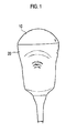
- the prior art ultrasonic probe includes a cover 10 , which may be in contact with a subject to be inspected and a case 20 for accommodating a transducer with a plurality of ultrasonic elements.
- the transducer may be rotated in the cover 10 so that three-dimensional ultrasonic imaging can be made.
- a device for rotating the transducer is mounted inside the case 20.
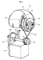
- the device comprises: a step motor 110; a speed reducer having a drive pulley (not shown), a driven pulley 130 and a belt 120 connecting the drive pulley and the driven pulley 130; a wire-rope holder 150 coupled to the speed reducer by a shaft 140; a transducer 170 having a plurality of ultrasonic elements and a rotating shaft 175; and a pair of wire ropes 160, one ends of which are connected to the wire-rope holder 150 and the other ends of which are connected to both lateral sides of the transducer 170.
- the wire-rope holder 150 includes a buffer spring 151 for absorbing a shock on the wire-ropes 160 during rotation of the transducer 170.
- the transducer 170 includes: a plurality of the ultrasonic elements 171; a transducer holder 172 for coupling the transducer to the rotating shaft 175; and a pair of wire-rope guides 173 having a slit 174 for coupling the other end of each wire-rope 160 thereto.
- a transducer holder 172 for coupling the transducer to the rotating shaft 175
- a pair of wire-rope guides 173 having a slit 174 for coupling the other end of each wire-rope 160 thereto.
- one end of each wire-rope 160 is knotted to the wire-rope holder 150, while the other end thereof is coupled to the slit 174 of the wire-rope guide 173.
- the wire-rope holder 150 has a buffer spring 151, both ends of which are bent like a hook. One end of each wire-rope 160 is knotted to each end of the buffer spring 151. A coupler 162 is provided at the other end of each wire-rope 160. The one end of the wire-rope 160 is inserted in the slit 174 as the coupler 162 is caught in the slit 174.
- each wire-rope 160 is first caught by each end of the buffer spring 151, while the other end thereof is then hooked to the slit 174 of the transducer 170. Accordingly, there is a problem with the wire-rope coupling of the prior art ultrasonic probe in that the worker must apply a large force to each wire rope 160. This is so that the buffer spring 151 expands sufficiently enough in order to hook the other end of the wire-rope to the slit 174.
- Fig. 1 is a front view of a prior art ultrasonic probe for conducting a three-dimensional imaging.
- Fig. 2 is a perspective view showing an internal structure of the prior art ultrasonic probe for conducting the three dimensional imaging.
- Fig. 3 is an exploded view showing a wire-rope holder of the prior art ultrasonic probe shown in Fig. 2 .
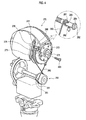
- Fig. 4 is a perspective view showing an internal structure of an ultrasonic probe for three-dimensional imaging with a device for coupling a wire-rope to a transducer constructed in accordance with an embodiment of the present invention.
- Fig. 5 is an enlarged perspective view of the device for coupling a wire-rope to a transducer of the ultrasonic probe shown in Fig. 4 .
- Fig. 6 is a side view of the device for coupling a wire-rope to a transducer shown in Fig. 5 .
- each wire rope 260 is hooked to a wire-rope holder 250. More specifically, a knot 261 provided at one end of the wire-rope 260 is hooked to a buffer spring 251 of the wire-rope holder 250.
- the buffer spring 251 is a coil spring with both ends bent like a hook for coupling the knot 261 of the wire-rope 260 thereto.
- a pair of wire ropes 260 are disposed in the shape of 8-figure.
- each wire-rope 260 is coupled to a transducer 270.
- Each wire-rope 260 is guided by a wire-rope guide 273.
- a coupler 262 is provided at the other end of the wire-rope 260.
- a wire-rope tightening bolt 280 is fastened to the transducer 270.
- a through-hole 281 is formed at the wire-rope tightening bolt 280.
- the wire-rope 260 is inserted through the through-hole 281.
- the coupler 262 prevents the wire-rope 260 from unfastening from the wire-rope tightening bolt 280.
- the transducer 270 further includes: a bracket 277 for fixing the wire-rope guide 273 to the transducer 270; and a first threaded hole 278 formed at a lateral side thereof.
- At least one holding groove 282 is formed at a periphery of a head of the wire-rope tightening bolt 280.
- the shape of the groove 282 corresponds to the head shape of a screw 283.
- a washer 284 is formed around the head of the wire-rope tightening bolt 280.
- the wire-rope tightening bolt 280 is inserted into the first threaded hole 278.
- a second threaded hole 276 is formed at the lateral side of the transducer 270 so as to be parallel to the first threaded hole 278.
- a screw 283 is fastened in the second threaded hole 276.
- the head of the screw 283 is engaged to one of the holding grooves 282 to thereby hold the wire-rope tightening bolt 280 in position.
- the wire-rope tightening bolt 280 is prevented from being rotated as its head and the head of the screw 283 are engaged to each other. Accordingly, the wire-rope 260 can maintain its tension.
- the screw 283 presses the washer 284 of the wirc-rope tightening bolt 280 the coupling between the wire-rope tightening bolt 280 and the transducer 270 can be intensified.
- each wire-rope 260 is hooked to the bent end of the buffer spring 251 of the wire-rope holder 250.
- the wire ropes 260 are disposed as being crossed to each other, while the other ends thereof are coupled to the transducer 270.
- Each wire-rope 260 is first inserted into the through-hole 281. Then, the coupler 262 is attached to the other end of the wire-rope 260. Thereafter, the wire-rope tightening bolt 280 is screw-engaged to the first threaded hole 278. As the wire-rope tightening bolt 280 is rotated, the wire rope 260 is tightened or slackened off accordingly.
- the screw 283 is screw-engaged to the second threaded hole 276 of the transducer 270.
- the head of the screw 283 is engaged to one of the holding grooves 282 of the wire-rope tightening bolt 280.
- the wire-rope tightening bolt 280 cannot be rotated at all and the desirably applied tension of the wire-rope 260 can be maintained as it is.
- a worker assembling the ultrasonic probe docs not need to apply any force to the buffer spring 251 to connect the wire-rope 260 to the transducer 270.
- the worker can easily tighten or slacken the wire-rope 260 only by using a small driver.
- the tension of the wire-rope can be precisely or desirably adjusted only by varying the fastening extent of the wire-rope tightening bolt 280.
- the transducer 270 can be rotated precisely without any error due to the wire-rope 260 with a constant tension applied thereto.
- the ultrasonic probe comprising such wire-rope coupling device allows a more accurate three-dimensional imaging.
- Embodiments of the present invention may provide an ultrasonic probe comprising a pair of alternately pulled wire-ropes for transmitting a drive force from a drive portion to a transducer and a device for coupling the wire-rope to the transducer.
- the device may comprise a bolt rotatably coupled to the transducer for tightening the wire-rope.
- the bolt may have a through-hole, into which the wire-rope is inserted and to which the wire-rope is coupled.
- the device may further comprise a wire-rope coupler provided at one end of the wire-rope inserted into the through-hole.
- the wire-rope coupler may prevent the wire rope from unfastening from the through-hole.
- the other end of the wire-rope may be hooked to the drive portion.
- the bolt may be screw-engaged to the transducer.
- the bolt may include a head having at least one holding groove at a periphery thereof.
- a device may further include a screw coupled to the transducer.
- the screw may have a head engaged to one of the holding grooves.
- the bolt may further include a washer pressed by the head of the screw.
- any reference in this specification to "one embodiment,” “an embodiment,” “example embodiment,” etc. means that a particular feature, structure or characteristic described in connection with the embodiment is included in at least one embodiment of the present invention.
- the appearances of such phrases in various places in the specification are not necessarily all referring to the same embodiment.
Landscapes
- Health & Medical Sciences (AREA)
- Life Sciences & Earth Sciences (AREA)
- Engineering & Computer Science (AREA)
- Physics & Mathematics (AREA)
- Medical Informatics (AREA)
- Animal Behavior & Ethology (AREA)
- Biophysics (AREA)
- Nuclear Medicine, Radiotherapy & Molecular Imaging (AREA)
- Pathology (AREA)
- Radiology & Medical Imaging (AREA)
- Biomedical Technology (AREA)
- Heart & Thoracic Surgery (AREA)
- Veterinary Medicine (AREA)
- Molecular Biology (AREA)
- Surgery (AREA)
- Public Health (AREA)
- General Health & Medical Sciences (AREA)
- Acoustics & Sound (AREA)
- Radar, Positioning & Navigation (AREA)
- Remote Sensing (AREA)
- Multimedia (AREA)
- Computer Networks & Wireless Communication (AREA)
- General Physics & Mathematics (AREA)
- Gynecology & Obstetrics (AREA)
- Ultra Sonic Daignosis Equipment (AREA)
Abstract
Embodiments of the present invention may provide an ultrasonic probe having a device for coupling a wire-rope to a transducer. A worker can easily couple the wire-rope to the transducer and can conveniently adjust the tension of the wire-rope. The ultrasonic probe has a pair of wire-ropes transmitting a drive force from a driving portion to the transducer by alternately pulling it at both sides thereof for rotating the transducer. The device comprises a wire-rope tightening bolt having a through-hole to which a wire-rope is inserted, wherein the wire-rope tightening bolt is rotatably coupled to the transducer.
Description
- The present application claims priority from
Korean Patent Application No. 10-2007-0000615 filed on January 3, 2007 - The present invention generally relates to an ultrasonic probe, and more particularly, to an ultrasonic probe having a device for coupling a wire-rope to a transducer for use with an ultrasonic diagnostic apparatus.
- An ultrasonic diagnostic apparatus is widely used to diagnose a subject by visualizing a portion of the subject's body. For example, the ultrasonic diagnostic apparatus diagnoses a subject by detecting alien substances of organs, measuring the level of a lesion, or observing a tumor or a fetus. Such ultrasonic diagnostic apparatus generally employs various ultrasonic probes in order to obtain information on a subject's body. The ultrasonic probe has a transducer, which emits ultrasonic waves into an inspection portion of a subject and receives the reflected ultrasonic waves therefrom to convert the reflected ultrasonic waves into electric signals. The ultrasonic diagnostic apparatus processes the electric signals from the ultrasonic probe, thereby forming an ultrasonic image that shows the inspection portion of a subject's body. In the recent years, ultrasonic probes configured to rotate the transducer are used to obtain a more accurate or three-dimensional ultrasonic image. Such ultrasonic probes employ a device for rotating a transducer therein. The device for rotating a transducer may be configured to transmit a drive force from a drive motor to the transducer via a pair of wire-ropes, which can absorb a shock produced during a rotation of the transducer.
- One example of a prior art ultrasonic probe for conducting a three-dimensional imaging is shown in
Figs. 1 to 3 . - As shown in
Figs. 1 and2 , the prior art ultrasonic probe includes acover 10 , which may be in contact with a subject to be inspected and acase 20 for accommodating a transducer with a plurality of ultrasonic elements. The transducer may be rotated in thecover 10 so that three-dimensional ultrasonic imaging can be made. - A device for rotating the transducer is mounted inside the
case 20. The device comprises: astep motor 110; a speed reducer having a drive pulley (not shown), a drivenpulley 130 and abelt 120 connecting the drive pulley and the drivenpulley 130; a wire-rope holder 150 coupled to the speed reducer by ashaft 140; atransducer 170 having a plurality of ultrasonic elements and arotating shaft 175; and a pair ofwire ropes 160, one ends of which are connected to the wire-rope holder 150 and the other ends of which are connected to both lateral sides of thetransducer 170. The wire-rope holder 150 includes abuffer spring 151 for absorbing a shock on the wire-ropes 160 during rotation of thetransducer 170. - The
transducer 170 includes: a plurality of theultrasonic elements 171; atransducer holder 172 for coupling the transducer to the rotatingshaft 175; and a pair of wire-rope guides 173 having aslit 174 for coupling the other end of each wire-rope 160 thereto. Thus, one end of each wire-rope 160 is knotted to the wire-rope holder 150, while the other end thereof is coupled to theslit 174 of the wire-rope guide 173. - As shown in
Figs. 2 and3 , the wire-rope holder 150 has abuffer spring 151, both ends of which are bent like a hook. One end of each wire-rope 160 is knotted to each end of thebuffer spring 151. Acoupler 162 is provided at the other end of each wire-rope 160. The one end of the wire-rope 160 is inserted in theslit 174 as thecoupler 162 is caught in theslit 174. - In the above-described ultrasonic probe, one end of each wire-
rope 160 is first caught by each end of thebuffer spring 151, while the other end thereof is then hooked to theslit 174 of thetransducer 170. Accordingly, there is a problem with the wire-rope coupling of the prior art ultrasonic probe in that the worker must apply a large force to eachwire rope 160. This is so that thebuffer spring 151 expands sufficiently enough in order to hook the other end of the wire-rope to theslit 174. - There is a further problem with the prior art ultrasonic probe in that a tension applied to the wire-rope cannot be adjusted since the length of the wire-rope cannot be changed once the ultrasonic prove is assembled.
- Arrangements and embodiments may be described in detail with reference to the following drawings in which like reference numerals refer to like elements and wherein:
-
Fig. 1 is a front view of a prior art ultrasonic probe for conducting a three-dimensional imaging. -
Fig. 2 is a perspective view showing an internal structure of the prior art ultrasonic probe for conducting the three dimensional imaging. -
Fig. 3 is an exploded view showing a wire-rope holder of the prior art ultrasonic probe shown inFig. 2 . -
Fig. 4 is a perspective view showing an internal structure of an ultrasonic probe for three-dimensional imaging with a device for coupling a wire-rope to a transducer constructed in accordance with an embodiment of the present invention. -
Fig. 5 is an enlarged perspective view of the device for coupling a wire-rope to a transducer of the ultrasonic probe shown inFig. 4 . -
Fig. 6 is a side view of the device for coupling a wire-rope to a transducer shown inFig. 5 . - A detailed description may be provided with reference to the accompanying drawings. One of ordinary skill in the art may realize that the following description is illustrative only and is not in any way limiting. Other embodiments of the present invention may readily suggest themselves to such skilled persons having the benefit of this disclosure.
- An ultrasonic probe having a device for coupling a wire-rope to a transducer, which is constructed in accordance with an embodiment of the present invention, will be now described in detail with reference to
Figs. 4 to 6 . - As shown in
Figs. 4 to 6 , one end of eachwire rope 260 is hooked to a wire-rope holder 250. More specifically, aknot 261 provided at one end of the wire-rope 260 is hooked to abuffer spring 251 of the wire-rope holder 250. Thebuffer spring 251 is a coil spring with both ends bent like a hook for coupling theknot 261 of the wire-rope 260 thereto. A pair ofwire ropes 260 are disposed in the shape of 8-figure. - The other end of each wire-
rope 260 is coupled to atransducer 270. Each wire-rope 260 is guided by a wire-rope guide 273. Acoupler 262 is provided at the other end of the wire-rope 260. A wire-rope tighteningbolt 280 is fastened to thetransducer 270. A through-hole 281 is formed at the wire-rope tighteningbolt 280. The wire-rope 260 is inserted through the through-hole 281. Thecoupler 262 prevents the wire-rope 260 from unfastening from the wire-rope tighteningbolt 280. - The
transducer 270 further includes: abracket 277 for fixing the wire-rope guide 273 to thetransducer 270; and a first threadedhole 278 formed at a lateral side thereof. At least oneholding groove 282 is formed at a periphery of a head of the wire-rope tighteningbolt 280. Preferably, the shape of thegroove 282 corresponds to the head shape of ascrew 283. Further, awasher 284 is formed around the head of the wire-rope tighteningbolt 280. The wire-rope tighteningbolt 280 is inserted into the first threadedhole 278. - A second threaded
hole 276 is formed at the lateral side of thetransducer 270 so as to be parallel to the first threadedhole 278. Ascrew 283 is fastened in the second threadedhole 276. To completely fasten thescrew 283, the head of thescrew 283 is engaged to one of theholding grooves 282 to thereby hold the wire-rope tighteningbolt 280 in position. Thus, the wire-rope tighteningbolt 280 is prevented from being rotated as its head and the head of thescrew 283 are engaged to each other. Accordingly, the wire-rope 260 can maintain its tension. Further, since thescrew 283 presses thewasher 284 of the wirc-rope tighteningbolt 280, the coupling between the wire-rope tighteningbolt 280 and thetransducer 270 can be intensified. - The coupling process of the wire-rope will now be described with reference to
Figs. 4 to 6 . - One end of each wire-
rope 260 is hooked to the bent end of thebuffer spring 251 of the wire-rope holder 250. Thewire ropes 260 are disposed as being crossed to each other, while the other ends thereof are coupled to thetransducer 270. Each wire-rope 260 is first inserted into the through-hole 281. Then, thecoupler 262 is attached to the other end of the wire-rope 260. Thereafter, the wire-rope tightening bolt 280 is screw-engaged to the first threadedhole 278. As the wire-rope tightening bolt 280 is rotated, thewire rope 260 is tightened or slackened off accordingly. - If a desired tension is applied to the wire-
rope 260, then thescrew 283 is screw-engaged to the second threadedhole 276 of thetransducer 270. In such a case, the head of thescrew 283 is engaged to one of the holdinggrooves 282 of the wire-rope tightening bolt 280. Thus, the wire-rope tightening bolt 280 cannot be rotated at all and the desirably applied tension of the wire-rope 260 can be maintained as it is. - Accordingly, a worker assembling the ultrasonic probe docs not need to apply any force to the
buffer spring 251 to connect the wire-rope 260 to thetransducer 270. In addition, the worker can easily tighten or slacken the wire-rope 260 only by using a small driver. - Further, the tension of the wire-rope can be precisely or desirably adjusted only by varying the fastening extent of the wire-
rope tightening bolt 280. Thus, thetransducer 270 can be rotated precisely without any error due to the wire-rope 260 with a constant tension applied thereto. Moreover, the ultrasonic probe comprising such wire-rope coupling device allows a more accurate three-dimensional imaging. - Embodiments of the present invention may provide an ultrasonic probe comprising a pair of alternately pulled wire-ropes for transmitting a drive force from a drive portion to a transducer and a device for coupling the wire-rope to the transducer. The device may comprise a bolt rotatably coupled to the transducer for tightening the wire-rope. The bolt may have a through-hole, into which the wire-rope is inserted and to which the wire-rope is coupled.
- The device may further comprise a wire-rope coupler provided at one end of the wire-rope inserted into the through-hole. The wire-rope coupler may prevent the wire rope from unfastening from the through-hole. The other end of the wire-rope may be hooked to the drive portion.
- The bolt may be screw-engaged to the transducer.
- The bolt may include a head having at least one holding groove at a periphery thereof. A device may further include a screw coupled to the transducer. The screw may have a head engaged to one of the holding grooves. The bolt may further include a washer pressed by the head of the screw.
- Any reference in this specification to "one embodiment," "an embodiment," "example embodiment," etc., means that a particular feature, structure or characteristic described in connection with the embodiment is included in at least one embodiment of the present invention. The appearances of such phrases in various places in the specification are not necessarily all referring to the same embodiment. Further, when a particular feature, structure or characteristic is described in connection with any embodiment, it is submitted that it is within the purview of one skilled in the art to effect such feature, structure or characteristic in connection with other ones of the embodiments of the present invention.
- Although embodiments of the present invention have been described with reference to a number of illustrative embodiments thereof, it should be understood that various other modifications and embodiments can be devised by those skilled in the art that will fall within the spirit and scope of the principles of this disclosure. More particularly, numerous variations and modifications are possible in the component parts and/or arrangements of the subject combination arrangement within the scope of the disclosure, the drawings and the appended claims. In addition to variations and modifications in the component parts and/or arrangements, alternative uses will also be apparent to those skilled in the art.
Claims (6)
- An ultrasonic probe comprising:a transducer;a pair of wire-ropes coupled to the transducer via bolts having through-holes so as to receive the respective wire-ropes, said bolts being rotatably coupled to the transducer for tightening the respective wire-ropes; anda drive unit configured to drive the pair of wire-ropes, wherein said wire-ropes are alternately pulled by the drive unit to rotate the transducer.
- The ultrasonic probe of Claim 1, further comprising a wire-rope coupler provided at one end of the wire-rope inserted into the through-hole, and wherein the wire-rope coupler prevents the wire rope from unfastening from the through-hole.
- The ultrasonic probe Claim 2, wherein the other end of the wire-rope is hooked to the drive portion.
- The ultrasonic probe of Claim 1, wherein the bolt is screw-engaged to the transducer.
- The device of any one of Claims 1 to 4, wherein the bolt includes a head having at least one holding groove at a periphery thereof, and
wherein the device further comprises a screw coupled to the transducer, the screw having a head engaged to one of the holding grooves. - The device of Claim 5, wherein the bolt further includes a washer pressed by the head of the screw.
Applications Claiming Priority (1)
| Application Number | Priority Date | Filing Date | Title |
|---|---|---|---|
| KR1020070000615A KR100951589B1 (en) | 2007-01-03 | 2007-01-03 | Ultrasonic probes with wire rope fixings for probe turning devices |
Publications (1)
| Publication Number | Publication Date |
|---|---|
| EP1941836A2 true EP1941836A2 (en) | 2008-07-09 |
Family
ID=39283748
Family Applications (1)
| Application Number | Title | Priority Date | Filing Date |
|---|---|---|---|
| EP08000007A Withdrawn EP1941836A2 (en) | 2007-01-03 | 2008-01-02 | Ultrasonic probe having a device for coupling a wire-rope to a transducer |
Country Status (3)
| Country | Link |
|---|---|
| US (1) | US7998078B2 (en) |
| EP (1) | EP1941836A2 (en) |
| KR (1) | KR100951589B1 (en) |
Cited By (1)
| Publication number | Priority date | Publication date | Assignee | Title |
|---|---|---|---|---|
| CN108348215A (en) * | 2015-10-29 | 2018-07-31 | 阿文特公司 | 3D ultrasonic image-forming systems for nerve block application |
Families Citing this family (12)
| Publication number | Priority date | Publication date | Assignee | Title |
|---|---|---|---|---|
| CN102018531B (en) * | 2009-09-21 | 2014-03-05 | 深圳迈瑞生物医疗电子股份有限公司 | Probe for ultrasonic imaging |
| CN102087122B (en) | 2009-12-02 | 2014-10-29 | 深圳迈瑞生物医疗电子股份有限公司 | 3D (three-dimensional) mechanical probe |
| CN102551792B (en) | 2010-12-27 | 2015-04-08 | 深圳迈瑞生物医疗电子股份有限公司 | Three-dimensional mechanical probe |
| KR101387934B1 (en) * | 2011-12-08 | 2014-04-23 | 삼성메디슨 주식회사 | Ultrasonic diagnostic apparatus |
| CN104235296B (en) * | 2013-06-19 | 2017-01-25 | 深圳迈瑞生物医疗电子股份有限公司 | Probe transmission device |
| KR102255420B1 (en) | 2014-03-19 | 2021-05-24 | 삼성메디슨 주식회사 | 3d ultrasonic probe |
| WO2016205632A1 (en) * | 2015-06-17 | 2016-12-22 | Berkeley Springs Instruments Llc | Transducer mounting apparatus |
| CN109717902B (en) * | 2019-01-23 | 2024-02-23 | 广州医科大学附属第二医院 | Oscillating abdominal ultrasound probe and method of use |
| CN111528908A (en) * | 2020-05-09 | 2020-08-14 | 上海爱声生物医疗科技有限公司 | B-ultrasonic equipment and probe thereof |
| KR102317198B1 (en) * | 2020-09-14 | 2021-10-26 | 신성욱 | Knife for farm mower |
| CN115523270B (en) * | 2022-10-26 | 2025-09-23 | 武汉联影医疗科技有限公司 | Rope transmission device, ultrasonic probe and ultrasonic equipment |
| CN115789191A (en) * | 2022-11-18 | 2023-03-14 | 武汉联影医疗科技有限公司 | Rope fastening device, rope transmission device and ultrasonic probe |
Family Cites Families (7)
| Publication number | Priority date | Publication date | Assignee | Title |
|---|---|---|---|---|
| US4203324A (en) * | 1977-08-05 | 1980-05-20 | Joseph Baumoel | Sonic liquid level detector |
| US5351692A (en) * | 1993-06-09 | 1994-10-04 | Capistrano Labs Inc. | Laparoscopic ultrasonic probe |
| AU4159097A (en) | 1996-08-30 | 1998-03-19 | Whitaker Corporation, The | Apparatus to flex a bendable probe |
| US7105956B2 (en) * | 2004-04-23 | 2006-09-12 | Aerotech, Inc. | High precision z-theta stage |
| KR100747094B1 (en) | 2005-07-15 | 2007-08-07 | 주식회사 메디슨 | Transducer Drive of Ultrasonic Probe |
| KR20080006072A (en) | 2006-07-11 | 2008-01-16 | 삼성전자주식회사 | LCD and its driving method |
| KR100949061B1 (en) * | 2006-12-27 | 2010-03-25 | 주식회사 메디슨 | Ultrasonic Oscillator Rotator of Probe of Ultrasonic Diagnostic Device |
-
2007
- 2007-01-03 KR KR1020070000615A patent/KR100951589B1/en active Active
-
2008
- 2008-01-02 EP EP08000007A patent/EP1941836A2/en not_active Withdrawn
- 2008-01-03 US US11/968,901 patent/US7998078B2/en active Active
Cited By (1)
| Publication number | Priority date | Publication date | Assignee | Title |
|---|---|---|---|---|
| CN108348215A (en) * | 2015-10-29 | 2018-07-31 | 阿文特公司 | 3D ultrasonic image-forming systems for nerve block application |
Also Published As
| Publication number | Publication date |
|---|---|
| US20080161695A1 (en) | 2008-07-03 |
| US7998078B2 (en) | 2011-08-16 |
| KR20080063964A (en) | 2008-07-08 |
| KR100951589B1 (en) | 2010-04-13 |
Similar Documents
| Publication | Publication Date | Title |
|---|---|---|
| US7998078B2 (en) | Ultrasonic probe having a device for coupling a wire-rope to a transducer | |
| US7819809B2 (en) | Device for pivoting an ultrasound element assembly of a probe in an ultrasonic diagnosis apparatus | |
| US7998077B2 (en) | Device for rotating a transducer of an ultrasonic probe | |
| US6569100B2 (en) | Ultrasonic probe and method of producing same | |
| JP3276008B2 (en) | Ultrasonic probe assembly | |
| US20110071399A1 (en) | Ultrasonic probe | |
| US20070016060A1 (en) | Device for moving a transducer of an ultrasonic probe | |
| CN115500862B (en) | A cavity volume probe and ultrasonic testing device | |
| US9142208B2 (en) | Ultrasonic probe and ultrasonic diagnostic equipment using same | |
| WO2023220879A1 (en) | Ultrasonic probe and ultrasonic imaging device | |
| CN102087122B (en) | 3D (three-dimensional) mechanical probe | |
| JPS61280850A (en) | Ultrasonic transducer probe assembly | |
| JP2000074764A (en) | Socket, torque wrench and gauge for measuring axial tension of bolt | |
| US8192365B2 (en) | Ultrasonic probe | |
| JP3731315B2 (en) | Ultrasound probe inserted endoscopically | |
| CN221712016U (en) | Ultrasonic body model mechanism | |
| US10806430B2 (en) | Probe transmission device | |
| JP3852183B2 (en) | Ultrasonic probe | |
| KR20070029891A (en) | Ultrasonic probe and ultrasonic element unit driving device | |
| US20240164753A1 (en) | Rope fixation device, rope transmission device, and ultrasound probe | |
| CN112345991A (en) | Magnetic resonance elastography excitation device and magnetic resonance elastography system | |
| CN118319359A (en) | Ultrasonic probe and medical instrument | |
| CN222723041U (en) | Ultrasonic volume probe and ultrasonic imaging equipment | |
| KR20080093470A (en) | Probe of Ultrasonic Diagnostic Device | |
| JP6380062B2 (en) | Ultrasonic probe |
Legal Events
| Date | Code | Title | Description |
|---|---|---|---|
| PUAI | Public reference made under article 153(3) epc to a published international application that has entered the european phase |
Free format text: ORIGINAL CODE: 0009012 |
|
| AK | Designated contracting states |
Kind code of ref document: A2 Designated state(s): AT BE BG CH CY CZ DE DK EE ES FI FR GB GR HR HU IE IS IT LI LT LU LV MC MT NL NO PL PT RO SE SI SK TR |
|
| AX | Request for extension of the european patent |
Extension state: AL BA MK RS |
|
| STAA | Information on the status of an ep patent application or granted ep patent |
Free format text: STATUS: THE APPLICATION IS DEEMED TO BE WITHDRAWN |
|
| 18D | Application deemed to be withdrawn |
Effective date: 20150801 |