EP1940189A2 - Apparatus and method for gathering and reporting interference signal information between relay stations in multi-hop relay broadband wireless access communication system - Google Patents
Apparatus and method for gathering and reporting interference signal information between relay stations in multi-hop relay broadband wireless access communication system Download PDFInfo
- Publication number
- EP1940189A2 EP1940189A2 EP07025139A EP07025139A EP1940189A2 EP 1940189 A2 EP1940189 A2 EP 1940189A2 EP 07025139 A EP07025139 A EP 07025139A EP 07025139 A EP07025139 A EP 07025139A EP 1940189 A2 EP1940189 A2 EP 1940189A2
- Authority
- EP
- European Patent Office
- Prior art keywords
- signal
- rss
- information
- period
- neighboring
- Prior art date
- Legal status (The legal status is an assumption and is not a legal conclusion. Google has not performed a legal analysis and makes no representation as to the accuracy of the status listed.)
- Granted
Links
- 238000000034 method Methods 0.000 title claims abstract description 98
- 238000004891 communication Methods 0.000 title claims abstract description 78
- 238000013468 resource allocation Methods 0.000 claims abstract description 72
- 230000005540 biological transmission Effects 0.000 abstract description 5
- 238000005259 measurement Methods 0.000 description 22
- 238000010187 selection method Methods 0.000 description 6
- 238000011144 upstream manufacturing Methods 0.000 description 6
- 230000008450 motivation Effects 0.000 description 2
- 238000000926 separation method Methods 0.000 description 2
- 230000007704 transition Effects 0.000 description 2
- 238000010276 construction Methods 0.000 description 1
- 230000006870 function Effects 0.000 description 1
Images


Classifications
-
- H—ELECTRICITY
- H04—ELECTRIC COMMUNICATION TECHNIQUE
- H04W—WIRELESS COMMUNICATION NETWORKS
- H04W72/00—Local resource management
- H04W72/20—Control channels or signalling for resource management
-
- H—ELECTRICITY
- H04—ELECTRIC COMMUNICATION TECHNIQUE
- H04B—TRANSMISSION
- H04B7/00—Radio transmission systems, i.e. using radiation field
- H04B7/24—Radio transmission systems, i.e. using radiation field for communication between two or more posts
- H04B7/26—Radio transmission systems, i.e. using radiation field for communication between two or more posts at least one of which is mobile
- H04B7/2603—Arrangements for wireless physical layer control
- H04B7/2606—Arrangements for base station coverage control, e.g. by using relays in tunnels
-
- H—ELECTRICITY
- H04—ELECTRIC COMMUNICATION TECHNIQUE
- H04W—WIRELESS COMMUNICATION NETWORKS
- H04W16/00—Network planning, e.g. coverage or traffic planning tools; Network deployment, e.g. resource partitioning or cells structures
- H04W16/24—Cell structures
- H04W16/26—Cell enhancers or enhancement, e.g. for tunnels, building shadow
-
- H—ELECTRICITY
- H04—ELECTRIC COMMUNICATION TECHNIQUE
- H04W—WIRELESS COMMUNICATION NETWORKS
- H04W84/00—Network topologies
- H04W84/18—Self-organising networks, e.g. ad-hoc networks or sensor networks
-
- H—ELECTRICITY
- H04—ELECTRIC COMMUNICATION TECHNIQUE
- H04B—TRANSMISSION
- H04B7/00—Radio transmission systems, i.e. using radiation field
- H04B7/14—Relay systems
- H04B7/15—Active relay systems
- H04B7/155—Ground-based stations
- H04B7/15528—Control of operation parameters of a relay station to exploit the physical medium
- H04B7/15542—Selecting at relay station its transmit and receive resources
-
- H—ELECTRICITY
- H04—ELECTRIC COMMUNICATION TECHNIQUE
- H04W—WIRELESS COMMUNICATION NETWORKS
- H04W72/00—Local resource management
- H04W72/50—Allocation or scheduling criteria for wireless resources
- H04W72/54—Allocation or scheduling criteria for wireless resources based on quality criteria
- H04W72/542—Allocation or scheduling criteria for wireless resources based on quality criteria using measured or perceived quality
-
- H—ELECTRICITY
- H04—ELECTRIC COMMUNICATION TECHNIQUE
- H04W—WIRELESS COMMUNICATION NETWORKS
- H04W84/00—Network topologies
- H04W84/02—Hierarchically pre-organised networks, e.g. paging networks, cellular networks, WLAN [Wireless Local Area Network] or WLL [Wireless Local Loop]
- H04W84/04—Large scale networks; Deep hierarchical networks
- H04W84/042—Public Land Mobile systems, e.g. cellular systems
- H04W84/047—Public Land Mobile systems, e.g. cellular systems using dedicated repeater stations
Definitions
- the present invention relates generally to a multi-hop relay Broadband Wireless Access (BWA) communication system, and more particularly, to an apparatus and method in which a Mobile Station (MS) or a Relay Station (RS) measures signals from neighboring Base Stations (BSs) and neighboring RSs, and when the RS transmits the measurement result to a BS as interference signal information, the BS computes a resource allocation to be used by the RS by using the interference signal information.
- BWA Broadband Wireless Access
- FIG. 1 illustrates a conventional scanning process for a handoff.
- the first MS 101 may be allocated with a scanning period by the first BS 103-1, or may request the first BS 103-1 to allocate a specific scanning period to the first MS 101.
- the first MS 101 terminates communication with the first BS 103-1, measures signal strength values of a second BS 103-2 and a third BS 103-3, and reports to the first BS 103-1 the signal strength values of the second BS 103-2 and the third BS 103-3.
- the signal strength values may be either Received Signal Strength Indicator (RSSI) values or Carrier to Interference and Noise Ratio (CINR) values.
- RSSI Received Signal Strength Indicator
- CINR Carrier to Interference and Noise Ratio
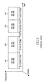
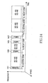
- FIG. 2 illustrates a physical frame structure when communication takes place in a multi-hop environment in a conventional Institute of Electrical and Electronics Engineers (IEEE) 802.16 Orthogonal Frequency Division Multiplexing (OFDM) system.
- IEEE Institute of Electrical and Electronics Engineers
- OFDM Orthogonal Frequency Division Multiplexing
- a DownLink (DL) frame is divided into an access zone 201 and a relay zone 203.
- the access zone 201 is used when a BS transmits data to MSs in the multi-hop environment or when a Relay Station (RS) transmits data to the MSs.
- the relay zone 203 is used when the BS transmits data to the RS or when the RS transmits data to a downstream RS.
- an UpLink (UL) frame is divided into an access zone 205 and a relay zone 207.
- the access zone 205 is used when the MSs transmit data to the BS or the RS
- the relay zone 207 is used when the RS transmits data to the BS or an upstream RS.
- the access and relay zones can spatially reuse resources according to signal interference between a BS and an RS. For example, when there is sufficient spatial separation between the BS and the RS to negate mutual signal interference, there is no interference between the BS and the RS when communication is made with MSs in the DL and UL access zones. However, when there is insufficient special separation between the BS and the RS, signal interference can be avoided only when the BS and the RS use different resources of the access zones in a time or frequency domain.
- An aspect of the present invention is to address at least the above-mentioned problems and/or disadvantages and to provide at least the advantages described below. Accordingly, an aspect of the present invention is to provide an apparatus and method for gathering and reporting interference signal information between RSs in a multi-hop relay BWA communication system.
- a method of computing a resource allocation of an RS in an entity having a right to control the RS in a BWA communication system includes receiving, from the RS, scanning information of neighboring BSs and neighboring RSs, computing the resource allocation to be used by the RS by using the received scanning information, and transmitting information on the computed resource allocation to the RS.
- a method of computing a resource allocation of an RS in an entity having a right to control the RS in a BWA communication system includes receiving scanning information of neighboring BSs and neighboring RSs from one or more MSs connected directly to the entity or from one or more MSs connected to the entity via the RS, computing the resource allocation to be used by the RS by using the received scanning information, and transmitting information on the computed resource allocation to the RS.
- an apparatus for computing a resource allocation of an RS in a BWA communication system includes the RS for scanning neighboring BSs and neighboring RSs and for transmitting scanning information to a BS, and the BS for computing the resource allocation to be used by the RS by using the scanning information and for transmitting information on the computed resource allocation to the RS.
- an apparatus for computing a resource allocation of an RS in a BWA communication system includes a BS for receiving scanning information of neighboring BSs and neighboring RSs from one or more MSs directly connected or from one or more MSs connected via the RS and for computing the resource allocation to be used by the RS by using the received scanning information, and the RS for receiving information on the computed resource allocation from the BS.
- an apparatus for computing a resource allocation of an RS in a BWA communication system includes the RS for computing a position coordinate value and for transmitting the computation result to a BS, and the BS for computing the resource allocation to be used by the RS by using the position coordinate value and for transmitting information on the computed resource allocation to the RS.
- a structure of a DL frame of a BS in a BWA communication system includes a first period for transmitting a preamble for measuring an interference signal to an MS, a second period for transmitting a signal to the MS, a third period for transmitting a signal to an RS, and a fourth period for transmitting a signal for measuring the interference signal to the RS.
- a frame structure of an RS in a BWA communication system includes a first DL period for transmitting a preamble for measuring an interference signal to an MS, a second DL period for transmitting a signal to the MS, a third DL period for receiving a signal from a BS, and a fourth DL period for transmitting, by some RSs, a signal for measuring the interference signal to remaining RSs and for measuring, by the remaining RSs, the interference signal by receiving the signal for measuring the interference signal.
- a frame structure of an RS group including a plurality of RSs in association with an odd hop in a BWA communication system includes a first DL period for transmitting a preamble for measuring an interference signal to an MS, a second DL period for transmitting a signal to the MS, a third DL period for receiving a signal from a BS or an RS group including a plurality of RSs in association with an even hop, a fourth DL period for measuring an interference signal by receiving a signal for measuring the interference signal from the BS or the RS group including the RSs in association with the even hop, a fifth DL period for transmitting a signal to the RS group including the RSs in association with the even hop, and a sixth DL period for transmitting the signal for measuring the interferences signal to the RS group including the RSs in association with the even hop.
- a DL frame structure of an RS group including a plurality of RSs in association with an even hop in a BWA communication system includes a first period for transmitting a preamble for measuring an interference signal to an MS, a second period for transmitting a signal to the MS, a third period for transmitting a signal to the RS group including a plurality of RSs in association with an odd hop, a fourth period for transmitting a signal for measuring the interference signal to the RS group including the RSs in association with the odd hop, a fifth period for receiving a signal from the RS group including the RSs in association with the odd hop, and a sixth period for receiving the signal for measuring the interference signal from the RS group including the RSs in association with the odd hop and for measuring the interference signal.
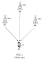
- FIGs. 3A and 3B illustrate a signal interference model in a multi-hop relay BWA communication system according to the present invention.
- a first MS 301 communicates with a first RS 305 in an access zone of FIG. 2 .
- the first MS 301 experiences signal interference from the first BS 303 and the second to fourth RSs 307, 309, and 311 in a DL direction (see FIG. 3A ).
- a signal transmitted from the first MS 301 to the first RS 305 causes signal interference to the first BS 303 and the second to fourth RSs 307, 309, and 311.
- a relay zone of FIG. 2 when the wireless resources of time and frequency are equally used when an RS communicates with a BS or another RS, signal interference occurs to neighboring BSs and neighboring RSs.
- FIG. 4 illustrates an operation of an RS that maximizes resources by using scanning information of neighboring BSs and neighboring RSs, which is measured in an initial access process, in a multi-hop relay BWA communication system according to the present invention.
- the RS when the multi-hop system is initially accessed, since there is no MS that receives a service from the RS, the RS may receive a preamble or pilot signal in an access zone of FIG. 2 . Therefore, the RS scans the neighboring BSs and the neighboring RSs by using the preamble or pilot signal and thus measures signal strength in step 401. Scanning information is stored in step 403. In step 405, initial access is attempted to a BS (or RS) which is determined to have the best signal quality or which satisfies a specific condition. The initial access is performed to establish DL and UL synchronizations with the BS (or RS) to be accessed by the RS.
- Examples of the scanning information may include signal strength values, station IDentifications (IDs), and preamble indices of the neighboring BSs and the neighboring RSs. Further, since the signal strength values are stored for each ID or preamble index, it is possible to distinguish the signal strength values of all the neighboring BSs and the neighboring RSs.
- IDs station IDentifications
- preamble indices of the neighboring BSs and the neighboring RSs.
- the RS receives the information on the resource allocation to be used by the RS from the upstream BS (or RS), and thus can start multi-hop communication by using the received information.
- the information on the resource allocation may vary according to a resource allocation algorithm used in the BS.
- the information may assign one or more RSs having less interference to one resource reuse group, indicate a resource use priority for a physical frame in a time or frequency domain, and indicate a time or frequency domain of a wireless resource that can be used by an RS.
- the information may be an indication about preamble or pilot channel used by an RS for a synchronization or scanning purpose in access zone or relay zone.
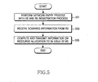
- FIG. 5 illustrates an operation of a BS that controls an RS when resources are reused by using scanning information of neighboring BSs and neighboring RSs, which is measured by the RS in an initial access process, in a multi-hop relay BWA communication system according to the present invention.
- the BS performs a network entry process with the RS and an RS registration process in step 501. Then, the BS receives scanning information from the RS in step 503. In step 505, the BS computes a resource allocation to be used by the newly connected RS by using the received scanning information, and transmits information on the computed resource allocation to the RS. It has been described that the BS has a right to control resource allocation of the RS to be connected. However, if an apparatus having such a right exists in the same place as another RS downstream of the BS or an access control station of a BS upstream of the BS, the information on the resource allocation is transmitted to the RS from an entity where the apparatus having the control right exists. Thereafter, the procedure of FIG. 5 ends.
- FIG. 6 illustrates an operation of an MS that scans neighboring BSs and neighboring RSs in a multi-hop relay BWA communication system according to the present invention.
- the MS measures strengths of pilot signals from the neighboring BSs and the neighboring RSs, that is, performs scanning in step 601. Then, the MS transmits the measured signal strength values (i.e., scanning information) to a BS (or RS) currently connected to the MS in step 603. Thereafter, the procedure of FIG. 6 ends.
- the measured signal strength values i.e., scanning information
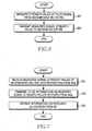
- FIG. 7 illustrates an operation of an RS that maximize resources by using scanning information of neighboring BSs and neighboring RSs, which is received from MSs, in a multi-hop relay BWA communication system according to the present invention.
- the RS receives signal strength values (i.e., scanning information) of the neighboring BSs and the neighboring RSs from the MSs currently connected to the RS in step 701.
- the signal strength values are measured by the MSs.
- the received values (i.e., scanning information) obtained by measuring signal strengths are transmitted to a BS in step 703.
- the RS receives information on a resource allocation from the BS in step 705. If an upstream entity that controls an interference signal of the RS is not the BS, the RS performs all of the aforementioned processes with respect to the entity that controls the interference signal. Thereafter, the procedure of FIG. 7 ends.
- FIG. 8 illustrates an operation of a BS that controls an RS when the RS maximizes resources by using scanning information of neighboring BSs and neighboring RSs, which is received from MSs, in a multi-hop relay BWA communication system according to the present invention.
- the BS receives scanning information from the MSs connected directly to the BS or connected to the RS in step 801.
- the scanning information is a value obtained by measuring signal strengths of the neighboring BSs and the neighboring RSs.
- the BS re-computes resource allocations of the BS and the RS, which have been determined in an initial access process.
- the BS transmits information on the computed resource allocations to the RS. Thereafter, the procedure of FIG. 8 ends.
- the RS receives the scanning information of the neighboring BSs and the neighboring RSs from the MSs, and transmits the received scanning information to the BS.
- the RS transmits scanning information of all MSs to the BS, a large amount of message overhead is produced.
- FIG. 9 illustrates the motivation for an RS to selectively transmit scanning information, which is received from MSs, to a BS in a multi-hop relay BWA communication system according to the present invention.
- a first RS 905 is a serving RS, to which is connected and a first MS 901 and a second MS 903.
- a second RS 907 interferes with the first RS 905. If the first MS 901 is closer in distance to the second RS 907 than the second MS 903, the first MS 901 experiences more interference with the second RS 907 than the second MS 903.
- the BS computes a resource allocation according to the first MS 901 that experiences more interference with the second RS 907 than the second MS 903. Therefore, even if the first RS 905 reports to the BS only a signal strength of the second RS 907 received from the first MS 901, there is no problem for the BS to determine an interference level of the second RS 907.
- RSSI R ( B ) S i - MS j RSSI R ( B ) S i - MS j , if , RSSI R ( B ) S i - MS j ⁇ RSSI Threshold
- CINR R ( B ) S i - MS j CINR R ( B ) S i - MS j , if , CINR R ( B ) S i - MS j ⁇ CINR Threshold
- the BS may estimate an interference level experienced by the MSs by using only one or two values received from the RS, and thus compute a resource allocation.
- a selection method may be determined by the RS.
- the selection method may be determined by the BS and is then reported to the RS.
- a message field is required so that the BS reports the determined selection method to the RS.
- the BS may transmit to the RS a first message filed that indicates an RSSI or CINR value which is used as a reference value. If the selection method determined by the BS is the same as described in the second embodiment, the BS may transmit to the RS a second message field that indicates the number of data values selected and reported for the BS or the RS. If the selection method determined by the BS is the same as described in the third embodiment, the BS may transmit to the RS both the first and second message fields described above. Upon receiving any one of the message fields, the RS reports to the BS the RSSI or CINR value according to a corresponding embodiment.
- the RS is no longer able to measure preamble and pilot signals of the neighboring BSs and the neighboring RSs, and is thus unable to transmit a scanning result to the BS.
- the RS may temporarily terminate communication with the MSs, and thus measure the preamble and pilot signals transmitted from the neighboring BSs and the neighboring RSs and report a scanning result to the BS.
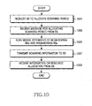
- FIG. 10 illustrates an operation of an RS that maximize resources by using scanning information of neighboring BSs and neighboring RSs, which is measured after an initial access process is performed, in a multi-hop relay BWA communication system according to the present invention.
- the RS requests a BS to allocate a scanning period in step 1001.
- the RS receives a message for allocating the scanning period from the BS.
- step 1001 may be omitted.
- the RS measures strengths of interference signals by scanning the neighboring BSs and the neighboring RSs, which transmit a preamble or pilot signal in an relay zone or access zone of FIG. 2 for the purpose of synchronization or scanning.
- the scanning period may be allocated when the RS determines that scanning is needed and thus requests the BS to allocate the scanning period.
- the scanning period may be allocated when the BS determines that the RS needs to perform scanning and thus allocates the scanning period to the RS.
- the neighboring BSs and the neighboring RSs to be scanned may be determined by the BS and neighboring stations' information to be scanned thereof may be included in the message for allocating the scanning period.
- the neighboring BSs and the neighboring RSs to be scanned may be determined by the RS itself. Steps 1001 and 1003 are performed only when the BS allocates the scanning period. Since the scanning period and the neighboring BSs and the neighboring RSs to be scanned can be determined by the RS, steps 1001 and 1003 may be skipped when scanning is determined and performed by the RS. In this case, the procedure begins with step 1005.
- the RS transmits measured values of signal strengths (i.e., scanning information) to the BS.
- the RS receives information on a resource allocation from the BS during the allocated scanning period. Then, the procedure of FIG. 10 ends.
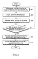
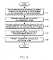
- FIG. 11 illustrates an operation of a BS that controls an RS when the RS maximizes resources by using scanning information of neighboring BSs and neighboring RSs, which is measured after an initial access process is performed, in a multi-hop relay BWA communication system according to the present invention.
- the BS receives a message for requesting scanning period allocation from the RS or determines that the RS needs to perform scanning in step 1101.
- step 1101 may be omitted.
- the BS allocates the scanning period to the RS.
- the BS transmits a message for allocating the scanning period to the RS.
- the message may include information on the neighboring BSs and the neighboring RSs to be scanned by the RS.
- steps 1101 and 1103 may be skipped when scanning is determined and performed by the RS. In this case, the procedure begins with step 1105.
- the BS receives scanning information from the RS, wherein the scanning information indicates measured values of signal strengths of neighboring BSs and neighboring RSs.
- the BS computes a resource allocation of the RS.
- the BS transmits information on the computed resource allocation to the RS.
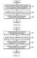
- FIG. 12 illustrates an operation of an RS that maximizes resources by using a position coordination value in a multi-hop relay BWA communication system according to the present invention.
- the RS receives a message for requesting a position coordinate value from a BS or determines that information update is necessary for a resource allocation when or after initial access is carried out.
- the RS transmits its position coordination value to the BS.
- the RS receives information on the resource allocation to be used by the RS itself from the BS. Thereafter, the procedure of FIG. 12 ends.
- FIG. 13 illustrates an operation of a BS that controls an RS when the RS maximizes resources by using a position coordinate value in a multi-hop relay BWA communication system according to the present invention.
- the BS transmits to the RS a message for requesting a position coordinate value of the RS.
- the BS receives the position coordinate value from the RS.
- the BS computes a resource allocation to be used by the RS according to information on the neighboring BSs and the neighboring RSs close in distance to the received position coordinate value of the RS.
- the BS transmits information on the computed resource allocation to the RS. Thereafter, the procedure of FIG. 13 ends.
- the BS may use both a first resource reuse method using scanning information as described in FIG. 4 to FIG. 11 and a second resource reuse method using a position coordinate value as described in FIGs. 12 and 13 . That is, in an initial access process, the RS may simultaneously transmit to the BS the scanning information of the neighboring BSs and the neighboring RSs of FIG. 4 and the position coordinate value of FIG. 12 , and thus the BS may compute a resource allocation of the RS by using the received scanning information and position coordinate value. In addition, as described in FIG. 7 or FIG. 10 , when the scanning information received from the MSs or scanning information obtained by the RS are transmitted to the BS, the RS also transmits the position coordinate value of FIG. 12 to the BS, so that the BS can compute the resource allocation of the RS.
- the BS may control scanning operations of a plurality of MSs or RSs as follows.
- the BS reports in advance, to the MSs or the RS, information on the neighboring BSs and the neighboring RSs to be scanned, when scanning is frequently performed for all of the neighboring BSs and the neighboring RSs, frequent scanning results in an increased overhead. Therefore, the BS may classify the neighboring BSs and the neighboring RSs to be scanned into groups and inform the RSs or the MSs of the classification result.
- some BSs or RSs which are adjacent to the first RS (or MS), and mobile RSs are classified in to a frequent-scanning group.
- the MSs or the RSs can report scanning information to the BS according to a time period of the other group. In this manner, an overhead of the scanning information of the neighboring BSs and the neighboring RSs can be effectively reduced when the scanning information is sent from the MSs or the RSs to the BS.
- the RS communicates with the MSs that receive services from the RS itself in the access zone and communicates with the BS or another RS in the relay zone.
- the operation of the RS that reuses resources by using the scanning information of the neighboring BSs and the neighboring RSs is described in FIG. 10 , wherein the scanning information is measured after the initial access process is performed.
- a specific signal to be measured by the RS in order to measure strengths of interference signals will be described with reference to FIG. 14 .
- FIG. 14 illustrates a method of measuring signal strengths of neighboring BSs and neighboring RSs, to which an RS transmits an interference signal, in a multi-hop relay BWA communication system according to the present invention.
- the RS measures the strength of the interference signal by using a preamble 1401 of each of the neighboring BSs and the neighboring RSs in an access zone.
- an additional overhead that reduces a wireless resource does not occur.
- the RS measures the preamble 1401 of each of the neighboring BSs and the neighboring RSs, the RS cannot communicate with an MS that is currently receiving a service from the RS.
- the RS measures an RSSI value or a CINR value of the preamble 1401 transmitted from the neighboring BS and the neighboring RS and transmits the measurement result to a BS as shown in FIG. 10 .
- the RS measures the strength of the interference signal by using ambles 1403, 1405, and 1407 transmitted between neighboring BSs and neighboring RSs in a relay zone.
- the ambles 1403, 1405, and 1407 are symbols transmitted for synchronization between a BS and an RS or between two RSs in a DL direction in the relay zone.
- the ambles 1403, 1405, and 1407 may be located at a first symbol (i.e., preamble) 1403 of the DL relay zone or a middle symbol (i.e., mid-amble) 1405, or a last symbol (i.e., post-amble) 1407.
- the RS can measure RSSI or CINR values of the ambles 1403, 1405, and 1407 transmitted from the neighboring BS and the neighboring RS and transmit the measurement result to the BS as shown in FIG. 10 .
- FIG. 15 illustrates a method of measuring signal strengths of neighboring BSs and neighboring RSs, to which an MS and an RS transmit interference signals, in a two-hop relay BWA communication system according to the present invention.
- the MSs In order to measure an interference signal from the neighboring BSs and the neighboring RSs, the MSs measure a signal strength of a preamble 1501 or 1507 in the DL access zone 1502 or 1508 of the BS or the RS and thus report scanning information to the BS or the RS. In this case, the RS retransmits to the BS the scanning information reported from the MSs.
- the RS measures (during a period indicated by 1510) a strength of a synch symbol 1504 or a pilot signal transmitted in the DL relay zone 1503 of the BS frame.
- FIG. 16 illustrates a method of measuring a signal strength of one RS group, to which one or more RSs transmit interference signals, in a two-hop relay BWA communication system according to the present invention.
- one RS group transmits a signature signal 1605 or 1608, a pilot signal, or a synch symbol for the synchronization or scanning purpose, each of which is used for identification to measure the interference signal, in a DL relay zone 1603 or a UL relay zone 1607.
- a plurality of remaining RSs other than one RS group measure (during a period indicated by 1612 or 1616) a strength of the interference signal by using the signature signal, the pilot signal, or the synch symbol.
- a Relay-Receive/transmit Transition Gap (R-RTG) 1604 is inserted in front of the signature signal 1605 in the DL relay zone 1603 of one RS group.
- a Relay-Transmit/receive Transition Gap (R-TTG) 1615 is inserted in front of the measurement period 1616 in the UL relay zone 1614 of the remaining RSs other than one RS group.
- FIG. 17 illustrates a method in which one RS group measures signal strengths of one or more RSs that transmit interference signals in a two-hop relay BWA communication system according to the present invention.
- the plurality of RSs transmit a signature signal 1713 or 1716, a pilot signal, or a synch symbol for the synchronization or scanning purpose, each of which is used for identification to measure the interference signals, in a DL relay zone 1711 or a UL relay zone 1715.
- one RS group measures (during a period indicated by 1704 or 1708) strengths of the interference signals by using the signature signal, the pilot signal, or the synch symbol, and reports the measurement result to a BS.
- An R-RTG 1712 is inserted in front of the signature signal 1713 in the DL relay zone 1711 of the plurality of RSs.
- An R-TTG 1707 is inserted in front of the measurement period 1708 in the UL relay 1706 of one RS group.
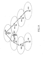
- FIG. 18 illustrates a multi-hop communication arrangement according to the present invention. It will be assumed herein that a BS 1809 and a plurality of RSs 1801, 1803, 1805, 1811, 1813, and 1815 have their own cell areas and communicate with MSs in the cell areas.
- the BS 1809 transmits data to the fifth RS (RS5) 1801 via the first RS (RS1) 1805 and the third RS (RS3) 1803. Further, the BS 1809 transmits data to the sixth RS (RS6) 1815 via the second RS (RS2) 1811 and the fourth RS (RS4) 1813.
- FIG. 19 illustrates frame structures of a BS and an RS in a multi-hop relay BWA communication system according to the present invention.
- a frame includes a BS frame, a first RS-group frame, and a second RS-group frame.
- RS1 1805, RS5 1801, RS2 1811, and RS6 1815 are classified into a first RS-group
- RS3 1803 and RS4 1813 are classified into a second RS-group.
- the BS frame includes access zones 1902 and 1905, relay zones 1903 and 1906, and zones 1904 and 1907 in which both the access zones and the relay zones are available.
- the first RS-group frame includes access zones 1909 and 1912 and two different relay zones, that is, first relay zones 1910 and 1913 and second relay zones 1911 and 1914.
- the second RS-group frame includes access zones 1916 and 1919 and two different relay zones, that is, first relay zones 1917 and 1920 and second relay zones 1918 and 1921.
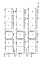
- FIG. 20 illustrates a method in which an MS measures signal strengths of BSs and RSs transmitting interference signals, and RSs belonging to first and second RS-groups measure signal strengths of the BSs transmitting interference signals and signal strengths of RSs belonging to another group in a multi-hop relay BWA communication system according to the present invention.
- the MS measures signal strengths of preambles 2001, 2011, and 2021 or synch symbols that are transmitted in DL access zones 2002, 2012, and 2022 of the BSs and the RSs, and reports the measurement result to the BSs and the RSs.
- the RSs re-report to the BSs the signal strengths reported from the MS.
- an RS belonging to the first RS-group measures (during a period indicated by 2014) a strength of a synch symbol 2004 or 2024 or a signature signal transmitted in a DL relay zone 2003 or 2023 of the BSs or the second RS-group, and reports the measurement result to the BSs.
- An RS belonging to the second RS-group measures (during a period indicated by 2026) a strength of a synch symbol 2006 or 2016 or a signature signal transmitted in a DL relay zone 2005 or 2015 of the BSs or the first RS-group.
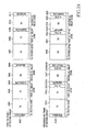
- FIG. 21 illustrates a method in which, in a first relay zone, a plurality of RSs belonging to a first RS-group measure a signal strength of a first RS belonging to the same group and transmitting an interference signal, and in a second relay zone, the first RS measures signal strengths of the plurality of RSs transmitting interference signals in a multi-hop relay BWA communication system according to the present invention.
- the first RS transmits the interference signal in first relay zones 2103 and 2110 and also transmits a signature signal 2105 or 2112, a pilot signal, or a synch signal, each of which is used for identification to measure the interference signal, in the first DL relay zone 2103 or the first UL relay zone 2110.
- R-RTGs 2104 and 2111 are inserted in front of the signature signals 2105 and 2112in the first DL relay zone 2103 and the first UL relay zone 2110 of the first RS.
- the remaining RSs transmit interference signals in second relay zones 2120 and 2125 and also transmit a signature signal 2121 or 2126a pilot signal, or a synch signal, each of which is used for identification to measure the interference signals, in the second DL relay zone 2120 or the second UL relay zone 2125.
- the first RS measures (during a period indicated by 2108 or 2115) a strength of an interference signal by using the signature signal, the pilot signal, or the synch signal, and then reports the measurement result to the BS.
- R-TTGs 2107 and 2114 are inserted in front of the signal strength measurement periods 2108 and 2115 in a second DL relay zone 2106 and a second UL relay zone 2113 of the first RS.
- FIG. 22 illustrates a method in which, in a first relay zone, a first RS belonging to a first RS-group measures signal strengths of a plurality of remaining RSs belonging to the same group and transmitting interference signals, and in a second relay zone, the remaining RSs measure a signal strength of the first RS transmitting an interference signal in a multi-hop relay BWA communication system according to the present invention.
- the remaining RSs transmit interference signals in first relay zones 2214 and 2221 and also transmit a signature signal 2216 or 2223a pilot signal, or a synch signal, each of which is used for identification to measure the interference signals, in the first DL relay zone 2214 or the first UL relay zone 2221.
- the first RS measures (during a period indicated by 2204 or 2209) strengths of the interference signals by using the signature signal, the pilot signal, or the synch signal, and the reports the measurement result to a BS.
- R-RTGs 2215 and 2222 are inserted in front of the signature signals 2216 and 2223 in the first DL relay zone 2214 and the first UL relay zone 2221 of the remaining RSs.
- the first RS transmits an interference signal in second relay zones 2205 and 2210 and also transmits a signature signal 2206 or 2211a pilot signal, or a synch signal, each of which is used for identification to measure the interference signal, in the second DL relay zone 2205 or the second UL relay zone 2210.
- the RSs measure (during a period indicated by 2219 or 2226) strengths of the interference signals by using the signature signal, the pilot signal, or the synch signal, and then report the measurement result to the BS.
- R-TTGs 2218 and 2225 are inserted in front of the signal strength measurement periods 2219 and 2226 in the second DL relay zone 2217 and the second UL relay zone 2224 of the remaining RSs.
- FIG. 23 illustrates a method in which, in a first relay zone, a first RS belonging to a second RS-group measures signal strengths of a plurality of remaining RSs belonging to the same group and transmitting interference signals, and in a second relay zone, the remaining RSs measure a signal strength of the first RS transmitting an interference signal in a multi-hop relay BWA communication system according to the present invention.
- the first RS transmits an interference signal in second relay zones 2306 and 2313 and also transmits a signature signal 2308 or 2315a pilot signal, or a synch signal, each of which is used for identification to measure the signal strength, in the second DL relay zone 2306 or the second UL relay zone 2313.
- the remaining RSs measure (during a period indicated by 2321 or 2326) a strength of the interference signal by using the signature signal, the pilot signal, or the synch signal, and then report the measurement result to the BS.
- R-TTGs 2307 and 2314 are inserted in front of the signature signal periods 2308 and 2315 in the second DL relay zone 2306 and the second UL relay zone 2313 of the first RS.
- FIG. 24 illustrates a method in which, in a first relay zone, a plurality of RSs belonging to a second RS-group measure a signal strength of a first RS belonging to the same group and transmitting an interference signal, and in a second relay zone, the first RS measures signal strengths of the plurality of RSs transmitting interference signals in a multi-hop relay BWA communication system according to the present invention.
- the first RS transmits the interference signal in first relay zones 2403 and 2408 and also transmits a signature signal 2404 or 2409, a pilot signal, or a synch signal, each of which is used for identification to measure the interference signal, in the first DL relay zone 2403 or the first UL relay zone 2408.
- a plurality of remaining RSs other than the first RS measure (during a period indicated by 2416 or 2423) the strength of the interference signal by using the signature signal, the pilot signal, or the synch signal, and then report the measurement result to a BS.
- R-TTGs 2415 and 2422 are inserted in front of the signal strength measurement periods 2416 and 2423 in a first DL relay zone 2414 and a first UL relay zone 2421 of the plurality of RSs.
- the plurality of RSs transmit the interference signals in second relay zones 2417 and 2424 and also transmit a signature signal 2419 or 2426a pilot signal, or a synch signal, each of which is used for identification to measure the interference signals, in the second DL relay zone 2417 or the second UL relay zone 2424.
- the first RS measures (indicated by 2406 or 2411) strengths of the interference signals by using the signature signal, the pilot signal, or the synch signal, and then reports the measurement result to the BS.
- R-RTGs 2418 and 2425 are inserted in front of the signature signal periods 2419 and 2426 in the second DL relay zone 2417 and the second DL relay zone 2424 of the plurality of RSs.
- a signature is defined in association with the second or third relay zone and is transmitted by BSs or RSs.
- the signature is in accordance with an index of the permutation value of the preamble, a cell ID (IDcell), and segment information.
- IDcell an index of the permutation value of the preamble
- segment information a cell ID (IDcell)
- the signature may be in accordance with an index of a permutation value of the signature, a cell ID, and segment information. That is, the permutation index, the cell ID, and the segment information of the signature may be the same as those of the preamble, or may be newly defined for each BS or RS.
- R-TTG is a period in which an RS switches from transmission to reception mode
- R-RTG is a period in which the RS switches from reception to transmission mode. Both the R-TTG and the R-RTG are defined in the second or third relay zone.
- the BS or the RS may transmit or receive a control signal so that a signature signal defined in the relay zone can be transmitted or received.
- an apparatus and method are provided in which an MS or an RS measures signals from neighboring BSs and neighboring RSs, and when the RS transmits the measurement result to a BS as interference signal information, the BS computes a resource allocation to be used by the RS by using the interference signal information. Therefore, there is an advantage in that wireless resources can be reused to the maximum extent. In addition, data transmission efficiency can be maximized.
- the structures disclosed in the present invention can be enabled by and recorded on a computer-readable medium.
- the structure of a DL frame of a BS herein can be enabled by and recorded on a computer-readable medium.
Abstract
Description
- This application claims priority under 35 U.S.C. § 119(a) to Korean patent applications filed in the Korean Intellectual Property Office on December 27, 2006 and assigned Serial
No. 2006-135566, on December 29, 2006 No. 2006-137681, on January 9, 2007 No. 2007-2619, and on January 19, 2007 No. 2007-6222 - The present invention relates generally to a multi-hop relay Broadband Wireless Access (BWA) communication system, and more particularly, to an apparatus and method in which a Mobile Station (MS) or a Relay Station (RS) measures signals from neighboring Base Stations (BSs) and neighboring RSs, and when the RS transmits the measurement result to a BS as interference signal information, the BS computes a resource allocation to be used by the RS by using the interference signal information.
-
FIG. 1 illustrates a conventional scanning process for a handoff. Referring toFIG. 1 , while communication takes place between a first Mobile Station (MS) 101 and a first Base Station (BS) 103-1, the first MS 101 may be allocated with a scanning period by the first BS 103-1, or may request the first BS 103-1 to allocate a specific scanning period to thefirst MS 101. During this period, thefirst MS 101 terminates communication with the first BS 103-1, measures signal strength values of a second BS 103-2 and a third BS 103-3, and reports to the first BS 103-1 the signal strength values of the second BS 103-2 and the third BS 103-3. The signal strength values may be either Received Signal Strength Indicator (RSSI) values or Carrier to Interference and Noise Ratio (CINR) values. In this case, the first BS 103-1 determines whether to perform a handoff of thefirst MS 101 by using the reported values. -
FIG. 2 illustrates a physical frame structure when communication takes place in a multi-hop environment in a conventional Institute of Electrical and Electronics Engineers (IEEE) 802.16 Orthogonal Frequency Division Multiplexing (OFDM) system. - Referring to
FIG. 2 , a DownLink (DL) frame is divided into anaccess zone 201 and arelay zone 203. Theaccess zone 201 is used when a BS transmits data to MSs in the multi-hop environment or when a Relay Station (RS) transmits data to the MSs. Therelay zone 203 is used when the BS transmits data to the RS or when the RS transmits data to a downstream RS. Likewise, an UpLink (UL) frame is divided into anaccess zone 205 and arelay zone 207. In contrast with the DL frame, theaccess zone 205 is used when the MSs transmit data to the BS or the RS, and therelay zone 207 is used when the RS transmits data to the BS or an upstream RS. - The access and relay zones can spatially reuse resources according to signal interference between a BS and an RS. For example, when there is sufficient spatial separation between the BS and the RS to negate mutual signal interference, there is no interference between the BS and the RS when communication is made with MSs in the DL and UL access zones. However, when there is insufficient special separation between the BS and the RS, signal interference can be avoided only when the BS and the RS use different resources of the access zones in a time or frequency domain.
- An aspect of the present invention is to address at least the above-mentioned problems and/or disadvantages and to provide at least the advantages described below. Accordingly, an aspect of the present invention is to provide an apparatus and method for gathering and reporting interference signal information between RSs in a multi-hop relay BWA communication system.
- An aspect of the present invention is to provide an apparatus and method for maximizing reuse of wireless resources by measuring an interference signal and for maximizing data transmission efficiency in a multi-hop relay BWA communication system.
- An aspect of the present invention is to provide an apparatus and method in which an MS or an RS measures signals from neighboring BSs and neighboring RSs, and when the RS transmits the measurement result to a BS as interference signal information, the BS computes a resource allocation to be used by the RS by using the interference signal information.
- According to the present invention, a method of computing a resource allocation of an RS in an entity having a right to control the RS in a BWA communication system is provided. The method includes receiving, from the RS, scanning information of neighboring BSs and neighboring RSs, computing the resource allocation to be used by the RS by using the received scanning information, and transmitting information on the computed resource allocation to the RS.
- According to the present invention, a method of computing a resource allocation of an RS in an entity having a right to control the RS in a BWA communication system is provided. The method includes receiving scanning information of neighboring BSs and neighboring RSs from one or more MSs connected directly to the entity or from one or more MSs connected to the entity via the RS, computing the resource allocation to be used by the RS by using the received scanning information, and transmitting information on the computed resource allocation to the RS.
- According to the present invention, a method of computing a resource allocation of an RS in an entity having a right to control the RS in a BWA communication system is provided. The method includes receiving a position coordinate value from the RS, computing the resource allocation to be used by the RS by using the received position coordinate value, and transmitting information on the computed resource allocation to the RS.
- According to the present invention, an apparatus for computing a resource allocation of an RS in a BWA communication system is provided. The apparatus includes the RS for scanning neighboring BSs and neighboring RSs and for transmitting scanning information to a BS, and the BS for computing the resource allocation to be used by the RS by using the scanning information and for transmitting information on the computed resource allocation to the RS.
- According to the present invention, an apparatus for computing a resource allocation of an RS in a BWA communication system is provided. The apparatus includes a BS for receiving scanning information of neighboring BSs and neighboring RSs from one or more MSs directly connected or from one or more MSs connected via the RS and for computing the resource allocation to be used by the RS by using the received scanning information, and the RS for receiving information on the computed resource allocation from the BS.
- According to the present invention, an apparatus for computing a resource allocation of an RS in a BWA communication system is provided. The apparatus includes the RS for computing a position coordinate value and for transmitting the computation result to a BS, and the BS for computing the resource allocation to be used by the RS by using the position coordinate value and for transmitting information on the computed resource allocation to the RS.
- According to the present invention, a structure of a DL frame of a BS in a BWA communication system is provided. The structure includes a first period for transmitting a preamble for measuring an interference signal to an MS, a second period for transmitting a signal to the MS, a third period for transmitting a signal to an RS, and a fourth period for transmitting a signal for measuring the interference signal to the RS.
- According to the present invention, a structure of a DL frame of an RS in a BWA communication system is provided. The structure includes a first period for transmitting a preamble for measuring an interference signal to an MS, a second period for transmitting a signal to the MS, a third period for receiving a signal from a BS, and a fourth period for measuring the interference signal by receiving a signal for measuring the interference signal from the BS.
- According to the present invention, a frame structure of an RS in a BWA communication system is provided. The frame structure includes a first DL period for transmitting a preamble for measuring an interference signal to an MS, a second DL period for transmitting a signal to the MS, a third DL period for receiving a signal from a BS, and a fourth DL period for transmitting, by some RSs, a signal for measuring the interference signal to remaining RSs and for measuring, by the remaining RSs, the interference signal by receiving the signal for measuring the interference signal.
- According to the present invention, a frame structure of an RS group including a plurality of RSs in association with an odd hop in a BWA communication system is provided. The frame structure includes a first DL period for transmitting a preamble for measuring an interference signal to an MS, a second DL period for transmitting a signal to the MS, a third DL period for receiving a signal from a BS or an RS group including a plurality of RSs in association with an even hop, a fourth DL period for measuring an interference signal by receiving a signal for measuring the interference signal from the BS or the RS group including the RSs in association with the even hop, a fifth DL period for transmitting a signal to the RS group including the RSs in association with the even hop, and a sixth DL period for transmitting the signal for measuring the interferences signal to the RS group including the RSs in association with the even hop.
- According to the present invention, a DL frame structure of an RS group including a plurality of RSs in association with an even hop in a BWA communication system is provided. The structure includes a first period for transmitting a preamble for measuring an interference signal to an MS, a second period for transmitting a signal to the MS, a third period for transmitting a signal to the RS group including a plurality of RSs in association with an odd hop, a fourth period for transmitting a signal for measuring the interference signal to the RS group including the RSs in association with the odd hop, a fifth period for receiving a signal from the RS group including the RSs in association with the odd hop, and a sixth period for receiving the signal for measuring the interference signal from the RS group including the RSs in association with the odd hop and for measuring the interference signal.
- The above and other aspects, features and advantages of certain exemplary embodiments of the present invention will become more apparent from the following detailed description when taken in conjunction with the accompanying drawings in which:
-
FIG. 1 illustrates a conventional scanning process for a handoff; -
FIG. 2 illustrates a physical frame structure when communication takes place in a multi-hop environment in a conventional IEEE 802.16 OFDM system; -
FIGs. 3A and 3B illustrate a signal interference model in a multi-hop relay BWA communication system according to the present invention; -
FIG. 4 illustrates an operation of an RS that maximizes resources by using scanning information of neighboring BSs and neighboring RSs, which is measured in an initial access process, in a multi-hop relay BWA communication system according to the present invention; -
FIG. 5 illustrates an operation of a BS that controls an RS when resources are allocated by using scanning information of neighboring BSs and neighboring RSs, which is measured by the RS in an initial access process, in a multi-hop relay BWA communication system according to the present invention; -
FIG. 6 illustrates an operation of an MS that scans neighboring BSs and neighboring RSs in a multi-hop relay BWA communication system according to the present invention; -
FIG. 7 illustrates an operation of an RS that maximizes resources by using scanning information of neighboring BSs and neighboring RSs, which is received from MSs, in a multi-hop relay BWA communication system according to the present invention; -
FIG. 8 illustrates an operation of a BS that controls an RS when the RS maximizes resources by using scanning information of neighboring BSs and neighboring RSs, which is received from MSs, in a multi-hop relay BWA communication system according to the present invention; -
FIG. 9 illustrates the motivation for an RS to selectively transmit scanning information, which is received from MSs, to a BS in a multi-hop relay BWA communication system according to the present invention; -
FIG. 10 illustrates an operation of an RS that maximizes resources by using scanning information of neighboring BSs and neighboring RSs, which is measured after an initial access process is performed, in a multi-hop relay BWA communication system according to the present invention; -
FIG. 11 illustrates an operation of a BS that controls an RS when the RS maximizes resources by using scanning information of neighboring BSs and neighboring RSs, which is measured after an initial access process is performed, in a multi-hop relay BWA communication system according to the present invention; -
FIG. 12 illustrates an operation of an RS that maximizes resources by using a position coordination value in a multi-hop relay BWA communication system according to the present invention; -
FIG. 13 illustrates an operation of a BS that controls an RS when the RS maximizes resources by using a position coordinate value in a multi-hop relay BWA communication system according to the present invention; -
FIG. 14 illustrates a method of measuring signal strengths of neighboring BSs and neighboring RSs, to which an RS transmits an interference signal, in a multi-hop relay BWA communication system according to the present invention; -
FIG. 15 illustrates a method of measuring signal strengths of neighboring BSs and neighboring RSs, to which an MS and an RS transmit interference signals, in a two-hop relay BWA communication system according to the present invention; -
FIG. 16 illustrates a method of measuring a signal strength of a first RS, to which one or more RSs transmit interference signals, in a two-hop relay BWA communication system according to the present invention; -
FIG. 17 illustrates a method in which a first RS measures signal strengths of one or more RSs that transmit interference signals in a two-hop relay BWA communication system according to the present invention; -
FIG. 18 illustrates a multi-hop communication arrangement according to the present invention; -
FIG. 19 illustrates frame structures of a BS and an RS in a multi-hop relay BWA communication system according to the present invention; -
FIG. 20 illustrates a method in which an MS measures signal strengths of BSs and RSs transmitting interference signals, and RSs belonging to first and second RS-groups measure signal strengths of the BSs transmitting interference signals and signal strengths of RSs belonging to another group in a multi-hop relay BWA communication system according to the present invention; -
FIG. 21 illustrates a method in which, in a first relay zone, a plurality of RSs belonging to a first RS-group measure a signal strength of a first RS belonging to the same group and transmitting an interference signal, and in a second relay zone, the first RS measures signal strengths of the plurality of RSs transmitting interference signals in a multi-hop relay BWA communication system according to the present invention; -
FIG. 22 illustrates a method in which, in a first relay zone, a first RS belonging to a first RS-group measures signal strengths of a plurality of remaining RSs belonging to the same group and transmitting interference signals, and in a second relay zone, the remaining RSs measure a signal strength of the first RS transmitting an interference signal in a multi-hop relay BWA communication system according to the present invention; -
FIG. 23 illustrates a method in which, in a first relay zone, a first RS belonging to a second RS-group measures signal strengths of a plurality of remaining RSs belonging to the same group and transmitting interference signals, and in a second relay zone, the remaining RSs measure a signal strength of the first RS transmitting an interference signal in a multi-hop relay BWA communication system according to the present invention; and -
FIG. 24 illustrates a method in which, in a first relay zone, a plurality of RSs belonging to a second RS-group measure a signal strength of a first RS belonging to the same group and transmitting an interference signal, and in a second relay zone, the first RS measures signal strengths of the plurality of RSs transmitting interference signals in a multi-hop relay BWA communication system according to the present invention. - Preferred embodiments of the present invention will be described below with reference to the accompanying drawings. In the following description, well-known functions or constructions are not described in detail for the sake of clarity and conciseness.
-
FIGs. 3A and 3B illustrate a signal interference model in a multi-hop relay BWA communication system according to the present invention. - Referring to
FIGs. 3A and 3B , afirst MS 301 communicates with afirst RS 305 in an access zone ofFIG. 2 . When wireless resources of time and frequency are equally used by afirst BS 303 and second tofourth RSs 307,309and 311, thefirst MS 301 experiences signal interference from thefirst BS 303 and the second tofourth RSs FIG. 3A ). In addition, in a UL direction (seeFIG. 3B ), a signal transmitted from thefirst MS 301 to thefirst RS 305 causes signal interference to thefirst BS 303 and the second tofourth RSs FIG. 2 , when the wireless resources of time and frequency are equally used when an RS communicates with a BS or another RS, signal interference occurs to neighboring BSs and neighboring RSs. -
FIG. 4 illustrates an operation of an RS that maximizes resources by using scanning information of neighboring BSs and neighboring RSs, which is measured in an initial access process, in a multi-hop relay BWA communication system according to the present invention. - Referring to
FIG. 4 , when the multi-hop system is initially accessed, since there is no MS that receives a service from the RS, the RS may receive a preamble or pilot signal in an access zone ofFIG. 2 . Therefore, the RS scans the neighboring BSs and the neighboring RSs by using the preamble or pilot signal and thus measures signal strength instep 401. Scanning information is stored instep 403. Instep 405, initial access is attempted to a BS (or RS) which is determined to have the best signal quality or which satisfies a specific condition. The initial access is performed to establish DL and UL synchronizations with the BS (or RS) to be accessed by the RS. Examples of the scanning information may include signal strength values, station IDentifications (IDs), and preamble indices of the neighboring BSs and the neighboring RSs. Further, since the signal strength values are stored for each ID or preamble index, it is possible to distinguish the signal strength values of all the neighboring BSs and the neighboring RSs. - In
step 407, the RS performs a network entry process and an RS registration process, and determines whether the network entry process and the RS registration process have been successfully performed. If these processes have failed, the process returns to step 401 where the RS repeats the subsequent steps. If these processes have been successful, instep 409, the RS transmits the stored scanning information to the registered upstream BS (or RS). Upon receiving the scanning information, the upstream BS (or RS) determines a resource allocation which can be used by the RS, and transmits information on a resource allocation to the RS. - In
step 411, the RS receives the information on the resource allocation to be used by the RS from the upstream BS (or RS), and thus can start multi-hop communication by using the received information. The information on the resource allocation may vary according to a resource allocation algorithm used in the BS. For example, the information may assign one or more RSs having less interference to one resource reuse group, indicate a resource use priority for a physical frame in a time or frequency domain, and indicate a time or frequency domain of a wireless resource that can be used by an RS. In addition, the information may be an indication about preamble or pilot channel used by an RS for a synchronization or scanning purpose in access zone or relay zone. There are numerous possibilities for implementing the resource allocation algorithm in the present invention. However, explanation thereof will not be given for the sake of conciseness. - Thereafter, the procedure of
FIG. 4 ends. -
FIG. 5 illustrates an operation of a BS that controls an RS when resources are reused by using scanning information of neighboring BSs and neighboring RSs, which is measured by the RS in an initial access process, in a multi-hop relay BWA communication system according to the present invention. - Referring to
FIG. 5 , the BS performs a network entry process with the RS and an RS registration process instep 501. Then, the BS receives scanning information from the RS instep 503. Instep 505, the BS computes a resource allocation to be used by the newly connected RS by using the received scanning information, and transmits information on the computed resource allocation to the RS. It has been described that the BS has a right to control resource allocation of the RS to be connected. However, if an apparatus having such a right exists in the same place as another RS downstream of the BS or an access control station of a BS upstream of the BS, the information on the resource allocation is transmitted to the RS from an entity where the apparatus having the control right exists. Thereafter, the procedure ofFIG. 5 ends. -
FIG. 6 illustrates an operation of an MS that scans neighboring BSs and neighboring RSs in a multi-hop relay BWA communication system according to the present invention. - Referring to
FIG. 6 , in order to know an interference level of signals from the neighboring BSs and the neighboring RSs, the MS measures strengths of pilot signals from the neighboring BSs and the neighboring RSs, that is, performs scanning instep 601. Then, the MS transmits the measured signal strength values (i.e., scanning information) to a BS (or RS) currently connected to the MS instep 603. Thereafter, the procedure ofFIG. 6 ends. -
FIG. 7 illustrates an operation of an RS that maximize resources by using scanning information of neighboring BSs and neighboring RSs, which is received from MSs, in a multi-hop relay BWA communication system according to the present invention. - Referring to
FIG. 7 , the RS receives signal strength values (i.e., scanning information) of the neighboring BSs and the neighboring RSs from the MSs currently connected to the RS instep 701. Herein, the signal strength values are measured by the MSs. The received values (i.e., scanning information) obtained by measuring signal strengths are transmitted to a BS instep 703. Then, the RS receives information on a resource allocation from the BS instep 705. If an upstream entity that controls an interference signal of the RS is not the BS, the RS performs all of the aforementioned processes with respect to the entity that controls the interference signal. Thereafter, the procedure ofFIG. 7 ends. -
FIG. 8 illustrates an operation of a BS that controls an RS when the RS maximizes resources by using scanning information of neighboring BSs and neighboring RSs, which is received from MSs, in a multi-hop relay BWA communication system according to the present invention. - Referring to
FIG. 8 , the BS receives scanning information from the MSs connected directly to the BS or connected to the RS instep 801. Herein, the scanning information is a value obtained by measuring signal strengths of the neighboring BSs and the neighboring RSs. Instep 803, by using the scanning information, the BS re-computes resource allocations of the BS and the RS, which have been determined in an initial access process. Instep 805, the BS transmits information on the computed resource allocations to the RS. Thereafter, the procedure ofFIG. 8 ends. - In
FIG. 7 , the RS receives the scanning information of the neighboring BSs and the neighboring RSs from the MSs, and transmits the received scanning information to the BS. As such, when the RS transmits scanning information of all MSs to the BS, a large amount of message overhead is produced. Thus, it is necessary for the RS to selectively transmit the scanning information of the MSs to the BS. -
FIG. 9 illustrates the motivation for an RS to selectively transmit scanning information, which is received from MSs, to a BS in a multi-hop relay BWA communication system according to the present invention. - Referring to
FIG. 9 , afirst RS 905 is a serving RS, to which is connected and a first MS 901 and asecond MS 903. In addition, asecond RS 907 interferes with thefirst RS 905. If the first MS 901 is closer in distance to thesecond RS 907 than thesecond MS 903, the first MS 901 experiences more interference with thesecond RS 907 than thesecond MS 903. When a pilot signal strength of thesecond RS 907 is measured by the first MS 901 and thesecond MS 903 and is then reported to the BS via thefirst RS 905, the BS computes a resource allocation according to the first MS 901 that experiences more interference with thesecond RS 907 than thesecond MS 903. Therefore, even if thefirst RS 905 reports to the BS only a signal strength of thesecond RS 907 received from the first MS 901, there is no problem for the BS to determine an interference level of thesecond RS 907. - Although there are many methods used by the RS to select the MSs that transmit scanning information to the BS, the following embodiments will be described in the present invention.
- According to a first embodiment of the present invention, an RS receives scanning information of neighboring BSs and neighboring RSs other than the RS itself from MSs. Thereafter, among the received scanning information, only scanning information of an MS that has an interference signal having a strength that is greater than a threshold is reported to a BS. That is, when an RSSI value or a CINR value of an interference signal of an ith RS (or BS) is measured by a jth MS, only scanning information of a jth MS for which an RSSI or CINR value satisfies a threshold is selected and transmitted to the BS. This can be expressed by Equation (1) below.

- According to a second embodiment of the present invention, an RS receives scanning information of neighboring BSs and neighboring RSs other than the RS itself from MSs, and then reports to a BS only RSSI values or CINR values, that is, a number of pieces of scanning information having the greatest value for each neighboring BS and neighboring RS. For example, in Table 1 below, pieces of scanning information of each neighboring BS and neighboring RS, which are received by the RS from the MSs, are listed according to magnitudes. Although the RS can report all values listed in sorted order in Table 1 to the BS, in order to reduce an overhead, the RS may report to the BS one or more values having the greatest value for each neighboring BS and neighboring RS. As such, the BS may estimate an interference level experienced by the MSs by using only one or two values received from the RS, and thus compute a resource allocation.
Table 1 Sorting Order BS RS2 RS3 ... RSM 1 -20dB(m) -41dB(m) -38dB(m) -50dB(m) 2 -22dB(m) -48dB(m) -48dB(m) -60dB(m) 3 -28dB(m) -51dB(m) -52dB(m) -80dB(m) ... N -60dB(m) -80dB(m) -60dB(m) -100dB(m) - According to a third embodiment of the present invention, an RS receives scanning information of neighboring BSs and neighboring RSs other than the RS itself from MSs. Then, by combining the first and second embodiments, pieces of scanning information of the MSs are sorted as shown in Table 1 above, wherein the scanning information satisfies a threshold. Only one or more information pieces having the greatest values for each neighboring BS and neighboring RS are selected and transmitted to a BS.
- When an RS selects an MS that transmits scanning information to a BS, a selection method may be determined by the RS. Alternatively, the selection method may be determined by the BS and is then reported to the RS. In this case, a message field is required so that the BS reports the determined selection method to the RS.
- If the selection method determined by the BS is the same as described in the first embodiment, the BS may transmit to the RS a first message filed that indicates an RSSI or CINR value which is used as a reference value. If the selection method determined by the BS is the same as described in the second embodiment, the BS may transmit to the RS a second message field that indicates the number of data values selected and reported for the BS or the RS. If the selection method determined by the BS is the same as described in the third embodiment, the BS may transmit to the RS both the first and second message fields described above. Upon receiving any one of the message fields, the RS reports to the BS the RSSI or CINR value according to a corresponding embodiment.
- Meanwhile, after the initial access is performed, in order to transmit a preamble or pilot signal to the MSs that receive services, the RS is no longer able to measure preamble and pilot signals of the neighboring BSs and the neighboring RSs, and is thus unable to transmit a scanning result to the BS. Optionally, the RS may temporarily terminate communication with the MSs, and thus measure the preamble and pilot signals transmitted from the neighboring BSs and the neighboring RSs and report a scanning result to the BS.
-
FIG. 10 illustrates an operation of an RS that maximize resources by using scanning information of neighboring BSs and neighboring RSs, which is measured after an initial access process is performed, in a multi-hop relay BWA communication system according to the present invention. - Referring to
FIG. 10 , the RS requests a BS to allocate a scanning period instep 1001. Instep 1003, the RS receives a message for allocating the scanning period from the BS. When BS let RS scan neighboring stations,step 1001 may be omitted. Instep 1005, the RS measures strengths of interference signals by scanning the neighboring BSs and the neighboring RSs, which transmit a preamble or pilot signal in an relay zone or access zone ofFIG. 2 for the purpose of synchronization or scanning. As described above, the scanning period may be allocated when the RS determines that scanning is needed and thus requests the BS to allocate the scanning period. Alternatively, however, the scanning period may be allocated when the BS determines that the RS needs to perform scanning and thus allocates the scanning period to the RS. In addition, the neighboring BSs and the neighboring RSs to be scanned may be determined by the BS and neighboring stations' information to be scanned thereof may be included in the message for allocating the scanning period. Alternatively, the neighboring BSs and the neighboring RSs to be scanned may be determined by the RS itself.Steps step 1005. - In
step 1007, the RS transmits measured values of signal strengths (i.e., scanning information) to the BS. Instep 1009, the RS receives information on a resource allocation from the BS during the allocated scanning period. Then, the procedure ofFIG. 10 ends. -
FIG. 11 illustrates an operation of a BS that controls an RS when the RS maximizes resources by using scanning information of neighboring BSs and neighboring RSs, which is measured after an initial access process is performed, in a multi-hop relay BWA communication system according to the present invention. - Referring to
FIG. 11 , the BS receives a message for requesting scanning period allocation from the RS or determines that the RS needs to perform scanning instep 1101. When BS let RS scan neighboring stations,step 1101 may be omitted. Thereafter, the BS allocates the scanning period to the RS. Instep 1103, the BS transmits a message for allocating the scanning period to the RS. The message may include information on the neighboring BSs and the neighboring RSs to be scanned by the RS. When the scanning period and the neighboring BSs and the neighboring RSs to be scanned can be determined by the RS, steps 1101 and 1103 may be skipped when scanning is determined and performed by the RS. In this case, the procedure begins withstep 1105. - In
step 1105, the BS receives scanning information from the RS, wherein the scanning information indicates measured values of signal strengths of neighboring BSs and neighboring RSs. Instep 1107, by using the received scanning information, the BS computes a resource allocation of the RS. Instep 1109, the BS transmits information on the computed resource allocation to the RS. - Thereafter, the procedure of
FIG. 11 ends. - As mentioned above, in the initial access process, in order to know the neighboring BSs and the neighboring RSs that interfere with the RS itself, the RS measures interference signals from the neighboring BSs and the neighboring RSs. If the BS (or RS) includes a device capable of measuring a coordination value, for example, similar to a Global Positioning System (GPS), then the RS may report its coordination value to the BS without having to measure the interference signals as described above. Therefore, the BS can compute a resource allocation according to information on the neighboring BSs and the neighboring RSs close in distance from the RS that reports the coordination value. In the following descriptions, the position coordination value is a GPS value for example, wherein the GSP value is a three-dimensional coordination value including latitude, longitude, and altitude.
-
FIG. 12 illustrates an operation of an RS that maximizes resources by using a position coordination value in a multi-hop relay BWA communication system according to the present invention. - Referring to
FIG. 12 , instep 1201, the RS receives a message for requesting a position coordinate value from a BS or determines that information update is necessary for a resource allocation when or after initial access is carried out. Instep 1203, the RS transmits its position coordination value to the BS. Instep 1205, the RS receives information on the resource allocation to be used by the RS itself from the BS. Thereafter, the procedure ofFIG. 12 ends. -
FIG. 13 illustrates an operation of a BS that controls an RS when the RS maximizes resources by using a position coordinate value in a multi-hop relay BWA communication system according to the present invention. - Referring to
FIG. 13 , instep 1301, the BS transmits to the RS a message for requesting a position coordinate value of the RS. Instep 1303, the BS receives the position coordinate value from the RS. Instep 1305, the BS computes a resource allocation to be used by the RS according to information on the neighboring BSs and the neighboring RSs close in distance to the received position coordinate value of the RS. Instep 1307, the BS transmits information on the computed resource allocation to the RS. Thereafter, the procedure ofFIG. 13 ends. - The BS may use both a first resource reuse method using scanning information as described in
FIG. 4 to FIG. 11 and a second resource reuse method using a position coordinate value as described inFIGs. 12 and 13 . That is, in an initial access process, the RS may simultaneously transmit to the BS the scanning information of the neighboring BSs and the neighboring RSs ofFIG. 4 and the position coordinate value ofFIG. 12 , and thus the BS may compute a resource allocation of the RS by using the received scanning information and position coordinate value. In addition, as described inFIG. 7 orFIG. 10 , when the scanning information received from the MSs or scanning information obtained by the RS are transmitted to the BS, the RS also transmits the position coordinate value ofFIG. 12 to the BS, so that the BS can compute the resource allocation of the RS. - In
FIG. 6 to FIG. 11 , the BS may control scanning operations of a plurality of MSs or RSs as follows. When the BS reports in advance, to the MSs or the RS, information on the neighboring BSs and the neighboring RSs to be scanned, when scanning is frequently performed for all of the neighboring BSs and the neighboring RSs, frequent scanning results in an increased overhead. Therefore, the BS may classify the neighboring BSs and the neighboring RSs to be scanned into groups and inform the RSs or the MSs of the classification result. That is, with respect to a first RS (or MS) among a plurality of BSs or RSs, some BSs or RSs, which are adjacent to the first RS (or MS), and mobile RSs are classified in to a frequent-scanning group. Some neighboring BSs and neighboring RSs, which are far from the first RS (or MS) and thus interference is not significant, and fixed RSs are classified into a long-period scanning group. By informing the MSs or the RSs of group information, the MSs or the RSs can report scanning information to the BS according to a time period of the other group. In this manner, an overhead of the scanning information of the neighboring BSs and the neighboring RSs can be effectively reduced when the scanning information is sent from the MSs or the RSs to the BS. - In
FIGs. 10 and11 , after the initial access process is performed, the RS communicates with the MSs that receive services from the RS itself in the access zone and communicates with the BS or another RS in the relay zone. The operation of the RS that reuses resources by using the scanning information of the neighboring BSs and the neighboring RSs is described inFIG. 10 , wherein the scanning information is measured after the initial access process is performed. A specific signal to be measured by the RS in order to measure strengths of interference signals will be described with reference toFIG. 14 . -
FIG. 14 illustrates a method of measuring signal strengths of neighboring BSs and neighboring RSs, to which an RS transmits an interference signal, in a multi-hop relay BWA communication system according to the present invention. - Referring to
FIG. 14 , for measuring the strength of the interference signal of the RS, two methods are used as follows. In a first method, the RS measures the strength of the interference signal by using apreamble 1401 of each of the neighboring BSs and the neighboring RSs in an access zone. When using the first method, an additional overhead that reduces a wireless resource does not occur. However, while the RS measures thepreamble 1401 of each of the neighboring BSs and the neighboring RSs, the RS cannot communicate with an MS that is currently receiving a service from the RS. The RS measures an RSSI value or a CINR value of thepreamble 1401 transmitted from the neighboring BS and the neighboring RS and transmits the measurement result to a BS as shown inFIG. 10 . - In a second method, the RS measures the strength of the interference signal by using
ambles ambles ambles ambles ambles FIG. 10 . -
FIG. 15 illustrates a method of measuring signal strengths of neighboring BSs and neighboring RSs, to which an MS and an RS transmit interference signals, in a two-hop relay BWA communication system according to the present invention. - Referring to
FIG. 15 , in the two-hop environment, physical frame structures of a BS and the RS each include a DL sub-frame and a UL sub-frame. A first period of the DL or UL sub-frame includesaccess zones relay zones access zones relay zones - In order to measure an interference signal from the neighboring BSs and the neighboring RSs, the MSs measure a signal strength of a
preamble DL access zone - Further, in order to measure the interference signal from the BS, the RS measures (during a period indicated by 1510) a strength of a
synch symbol 1504 or a pilot signal transmitted in theDL relay zone 1503 of the BS frame. -
FIG. 16 illustrates a method of measuring a signal strength of one RS group, to which one or more RSs transmit interference signals, in a two-hop relay BWA communication system according to the present invention. - Referring to
FIG. 16 , one RS group transmits asignature signal DL relay zone 1603 or aUL relay zone 1607. A plurality of remaining RSs other than one RS group measure (during a period indicated by 1612 or 1616) a strength of the interference signal by using the signature signal, the pilot signal, or the synch symbol. - A Relay-Receive/transmit Transition Gap (R-RTG) 1604 is inserted in front of the
signature signal 1605 in theDL relay zone 1603 of one RS group. A Relay-Transmit/receive Transition Gap (R-TTG) 1615 is inserted in front of themeasurement period 1616 in theUL relay zone 1614 of the remaining RSs other than one RS group. -
FIG. 17 illustrates a method in which one RS group measures signal strengths of one or more RSs that transmit interference signals in a two-hop relay BWA communication system according to the present invention. - Referring to
FIG. 17 , the plurality of RSs transmit asignature signal DL relay zone 1711 or aUL relay zone 1715. one RS group measures (during a period indicated by 1704 or 1708) strengths of the interference signals by using the signature signal, the pilot signal, or the synch symbol, and reports the measurement result to a BS. - An R-
RTG 1712 is inserted in front of thesignature signal 1713 in theDL relay zone 1711 of the plurality of RSs. An R-TTG 1707 is inserted in front of themeasurement period 1708 in theUL relay 1706 of one RS group. -
FIG. 18 illustrates a multi-hop communication arrangement according to the present invention. It will be assumed herein that aBS 1809 and a plurality ofRSs - Referring to
FIG. 18 , theBS 1809 transmits data to the fifth RS (RS5) 1801 via the first RS (RS1) 1805 and the third RS (RS3) 1803. Further, theBS 1809 transmits data to the sixth RS (RS6) 1815 via the second RS (RS2) 1811 and the fourth RS (RS4) 1813. -
FIG. 19 illustrates frame structures of a BS and an RS in a multi-hop relay BWA communication system according to the present invention. - Referring to
FIG. 19 , a frame includes a BS frame, a first RS-group frame, and a second RS-group frame. There are various ways of grouping RSs. For example, inFIG. 18 ,RS1 1805,RS5 1801, RS2 1811, andRS6 1815, each of which corresponds to an odd hop, are classified into a first RS-group, andRS3 1803 and RS4 1813, each of which corresponds to an even hop, are classified into a second RS-group. - The BS frame includes
access zones relay zones zones access zones first relay zones second relay zones access zones first relay zones second relay zones -
FIG. 20 illustrates a method in which an MS measures signal strengths of BSs and RSs transmitting interference signals, and RSs belonging to first and second RS-groups measure signal strengths of the BSs transmitting interference signals and signal strengths of RSs belonging to another group in a multi-hop relay BWA communication system according to the present invention. - Referring to
FIG. 20 , the MS measures signal strengths ofpreambles DL access zones - Next, an RS belonging to the first RS-group measures (during a period indicated by 2014) a strength of a
synch symbol DL relay zone - An RS belonging to the second RS-group measures (during a period indicated by 2026) a strength of a
synch symbol DL relay zone - Only a DL frame scenario has been described above as an example. Although not shown, the same will also be applied to a UL frame scenario to measure strengths of interference signals.
-
FIG. 21 illustrates a method in which, in a first relay zone, a plurality of RSs belonging to a first RS-group measure a signal strength of a first RS belonging to the same group and transmitting an interference signal, and in a second relay zone, the first RS measures signal strengths of the plurality of RSs transmitting interference signals in a multi-hop relay BWA communication system according to the present invention. - Referring to
FIG. 21 , among all RSs belonging to the first RS-group, the first RS transmits the interference signal infirst relay zones signature signal 2105 or 2112, a pilot signal, or a synch signal, each of which is used for identification to measure the interference signal, in the firstDL relay zone 2103 or the firstUL relay zone 2110. A plurality of remaining RSs other than the first RS measure (during a period indicated by 2119 or 2124) of interferences signals by using the signature signal, the pilot signal, or the synch signal, and then report the measurement result to a BS. R-RTGs 2104 and 2111 are inserted in front of the signature signals 2105 and 2112in the firstDL relay zone 2103 and the firstUL relay zone 2110 of the first RS. - Next, among all RSs belonging to the first RS-group, the remaining RSs transmit interference signals in
second relay zones signature signal 2121 or 2126a pilot signal, or a synch signal, each of which is used for identification to measure the interference signals, in the secondDL relay zone 2120 or the secondUL relay zone 2125. The first RS measures (during a period indicated by 2108 or 2115) a strength of an interference signal by using the signature signal, the pilot signal, or the synch signal, and then reports the measurement result to the BS. R-TTGs strength measurement periods DL relay zone 2106 and a secondUL relay zone 2113 of the first RS. -
FIG. 22 illustrates a method in which, in a first relay zone, a first RS belonging to a first RS-group measures signal strengths of a plurality of remaining RSs belonging to the same group and transmitting interference signals, and in a second relay zone, the remaining RSs measure a signal strength of the first RS transmitting an interference signal in a multi-hop relay BWA communication system according to the present invention. - Referring to
FIG. 22 , among all RSs belonging to the first RS-group, the remaining RSs transmit interference signals infirst relay zones DL relay zone 2214 or the firstUL relay zone 2221. The first RS measures (during a period indicated by 2204 or 2209) strengths of the interference signals by using the signature signal, the pilot signal, or the synch signal, and the reports the measurement result to a BS. R-RTGs 2215 and 2222 are inserted in front of the signature signals 2216 and 2223 in the firstDL relay zone 2214 and the firstUL relay zone 2221 of the remaining RSs. - Next, among all RSs belonging to the first RS-group, the first RS transmits an interference signal in
second relay zones signature signal 2206 or 2211a pilot signal, or a synch signal, each of which is used for identification to measure the interference signal, in the secondDL relay zone 2205 or the secondUL relay zone 2210. The RSs measure (during a period indicated by 2219 or 2226) strengths of the interference signals by using the signature signal, the pilot signal, or the synch signal, and then report the measurement result to the BS. R-TTGs 2218 and 2225 are inserted in front of the signalstrength measurement periods 2219 and 2226 in the second DL relay zone 2217 and the secondUL relay zone 2224 of the remaining RSs. -
FIG. 23 illustrates a method in which, in a first relay zone, a first RS belonging to a second RS-group measures signal strengths of a plurality of remaining RSs belonging to the same group and transmitting interference signals, and in a second relay zone, the remaining RSs measure a signal strength of the first RS transmitting an interference signal in a multi-hop relay BWA communication system according to the present invention. - Referring to
FIG. 23 , among all RSs belonging to the second RS-group, the remaining RSs other than the first RS transmit interference signals infirst relay zones signature signal 2319 or 2324a pilot signal, or a synch signal, each of which is used for identification to measure the interference signals, in the firstDL relay zone 2318 or the firstUL relay zone 2323. The first RS measures strengths of the interference signals (during a period indicated by 2305 or 2312) by using the signature signal, the pilot signal, or the synch signal, and then reports the measurement result to a BS. R-TTGs 2304 and 2311 are inserted in front of the signalstrength measurement periods 2305 and 2312 in the firstDL relay zone 2303 and the firstUL relay zone 2310 of the first RS. - Next, among all RSs belonging to the second RS-group, the first RS transmits an interference signal in
second relay zones signature signal 2308 or 2315a pilot signal, or a synch signal, each of which is used for identification to measure the signal strength, in the secondDL relay zone 2306 or the secondUL relay zone 2313. The remaining RSs measure (during a period indicated by 2321 or 2326) a strength of the interference signal by using the signature signal, the pilot signal, or the synch signal, and then report the measurement result to the BS. R-TTGs signature signal periods DL relay zone 2306 and the secondUL relay zone 2313 of the first RS. -
FIG. 24 illustrates a method in which, in a first relay zone, a plurality of RSs belonging to a second RS-group measure a signal strength of a first RS belonging to the same group and transmitting an interference signal, and in a second relay zone, the first RS measures signal strengths of the plurality of RSs transmitting interference signals in a multi-hop relay BWA communication system according to the present invention. - Referring to
FIG. 24 , among all RSs belonging to the second RS-group, the first RS transmits the interference signal infirst relay zones signature signal DL relay zone 2403 or the firstUL relay zone 2408. A plurality of remaining RSs other than the first RS measure (during a period indicated by 2416 or 2423) the strength of the interference signal by using the signature signal, the pilot signal, or the synch signal, and then report the measurement result to a BS. R-TTGs 2415 and 2422are inserted in front of the signalstrength measurement periods 2416 and 2423 in a firstDL relay zone 2414 and a firstUL relay zone 2421 of the plurality of RSs. - Next, among all RSs belonging to the second RS-group, the plurality of RSs transmit the interference signals in
second relay zones DL relay zone 2417 or the secondUL relay zone 2424. The first RS measures (indicated by 2406 or 2411) strengths of the interference signals by using the signature signal, the pilot signal, or the synch signal, and then reports the measurement result to the BS. R-RTGs 2418 and 2425 are inserted in front of thesignature signal periods 2419 and 2426 in the secondDL relay zone 2417 and the secondDL relay zone 2424 of the plurality of RSs. - In the present invention, a signature is defined in association with the second or third relay zone and is transmitted by BSs or RSs. When a permutation value of a preamble defined in the first period is reused, the signature is in accordance with an index of the permutation value of the preamble, a cell ID (IDcell), and segment information. When the signature uses a newly defined permutation value, the signature may be in accordance with an index of a permutation value of the signature, a cell ID, and segment information. That is, the permutation index, the cell ID, and the segment information of the signature may be the same as those of the preamble, or may be newly defined for each BS or RS.
- Furthermore, in the present invention, R-TTG is a period in which an RS switches from transmission to reception mode, and R-RTG is a period in which the RS switches from reception to transmission mode. Both the R-TTG and the R-RTG are defined in the second or third relay zone. The BS or the RS may transmit or receive a control signal so that a signature signal defined in the relay zone can be transmitted or received.
- According to the present invention, an apparatus and method are provided in which an MS or an RS measures signals from neighboring BSs and neighboring RSs, and when the RS transmits the measurement result to a BS as interference signal information, the BS computes a resource allocation to be used by the RS by using the interference signal information. Therefore, there is an advantage in that wireless resources can be reused to the maximum extent. In addition, data transmission efficiency can be maximized. It is to be understood that the structures disclosed in the present invention can be enabled by and recorded on a computer-readable medium. For example, the structure of a DL frame of a BS herein can be enabled by and recorded on a computer-readable medium.
- While the invention has been shown and described with reference to certain exemplary embodiments thereof, it will be understood by those skilled in the art that various changes in form and details may be made therein without departing from the spirit and scope of the invention as defined by the appended claims and their equivalents. Therefore, the scope of the invention is defined not by the detailed description of the invention but by the appended claims and their equivalents, and all differences within the scope will be construed as being included in the present invention.
Claims (55)
- A method of computing a resource allocation of a Relay Station (RS) in an entity having a right to control the RS in a Broadband Wireless Access (BWA) communication system, the method comprising:receiving, from the RS, scanning information of neighboring Base Stations (BSs) and neighboring RSs;computing the resource allocation to be used by the RS by using the received scanning information; andtransmitting information on the computed resource allocation to the RS.
- The method of claim 1, further comprising, prior to the receiving of the scanning information, performing a network entry process with the RS and an RS registration process.
- The method of claim 1, further comprising, prior to the receiving of the scanning information:receiving a message for requesting scanning period allocation from the RS or determining, by the entity, that the RS needs to perform scanning; andallocating a scanning period to the RS, and transmitting a message including at least one of the allocated scanning period and information on the neighboring BSs and the neighboring RSs to be scanned by the RS.
- The method of claim 3, wherein the information on the neighboring BSs and the neighboring RSs to be scanned by the RS is information on a scanning group including the neighboring BSs and the neighboring RSs.
- The method of claim 4, wherein the scanning group is classified by using at least one of a distance from the RS, a mobility, and a signal strength, and classified scanning group has a different scanning period each other.
- The method of claim 1, wherein the scanning information includes at least one of signal strength values of the neighboring BSs and the neighboring RSs, IDentifications (IDs) of the neighboring BSs and the neighboring RSs, and preamble indices of the neighboring BSs and the neighboring RSs.
- The method of claim 6, wherein the signal strength value is a Received Signal Strength Indicator (RSSI) or Carrier to Interference and Noise Ratio (CINR) value that satisfies a threshold.
- The method of claim 1, wherein the information on the resource allocation is selected from a group consisting of information which assigns one or more RSs having less interference to one resource reuse group, information which indicates a resource use priority for a physical frame in a time or frequency domain, information which indicates a time or frequency domain of a wireless resource that can be used by an RS, and an indication about preamble or pilot channel used by an RS.
- A method of computing a resource allocation of a Relay Station (RS) in an entity having a right to control the RS in a Broadband Wireless Access (BWA) communication system, the method comprising:receiving scanning information of neighboring Base Stations (BSs) and neighboring RSs from one or more Mobile Stations (MSs) connected directly to the entity or from one or more MSs connected to the entity via the RS;computing the resource allocation to be used by the RS by using the received scanning information; andtransmitting information on the computed resource allocation to the RS.
- The method of claim 9, wherein the scanning information includes at least one of signal strength values of the neighboring BSs and the neighboring RSs, IDentifications (IDs) of the neighboring BSs and the neighboring RSs, and preamble indices of the neighboring BSs and the neighboring RSs.
- The method of claim 9, wherein the information on the resource allocation is selected from a group consisting of information which assigns one or more RSs having less interference to one resource reuse group, information which indicates a resource use priority for a physical frame in a time or frequency domain, information which indicates a time or frequency domain of a wireless resource that can be used by an RS, and an indication about preamble or pilot channel used by an RS.
- The method of claim 9, wherein the scanning information received through the RS includes first information corresponding to scanning information of an MS, which is one of the one or more MSs connected to the RS and of which scanning information is greater than or equal to a threshold, second information corresponding to a number of pieces of scanning information having the greatest value for each neighboring BS and neighboring RS, and third information in which the first information and the second information are combined.
- The method of claim 12, further comprising transmitting to the RS the threshold and at least one of the number of pieces of the scanning information.
- A method of computing a resource allocation of a Relay Station (RS) in an entity having a right to control the RS in a Broadband Wireless Access (BWA) communication system, the method comprising:receiving a position coordinate value from the RS;computing the resource allocation to be used by the RS by using the received position coordinate value; andtransmitting information on the computed resource allocation to the RS.
- The method of claim 14, further comprising transmitting a message for requesting the position coordinate value to the RS.
- The method of claim 14, wherein the information on the resource allocation is selected from a group consisting of information which assigns one or more RSs having less interference to one resource reuse group, information which indicates a resource use priority for a physical frame in a time or frequency domain, information which indicates a time or frequency domain of a wireless resource that can be used by an RS, and an indication about preamble or pilot channel used by an RS.
- An apparatus for computing a resource allocation of a Relay Station (RS) in a Broadband Wireless Access (BWA) communication system, the apparatus comprising:the RS for scanning neighboring Base Stations (BSs) and neighboring RSs and for transmitting scanning information to a BS; andthe BS for computing the resource allocation to be used by the RS by using the scanning information and for transmitting information on the computed resource allocation to the RS.
- The apparatus of claim 17, wherein, after the scanning is performed and before the scanning information is transmitted, the RS performs a network entry process with the BS and an RS registration process.
- The apparatus of claim 17, wherein, when a message for requesting scanning period allocation is received from the RS or when the BS determines that the RS needs to perform scanning, the BS allocates a scanning period to the RS and transmits to the RS a message including at least one of the allocated scanning period and information on the neighboring BSs and the neighboring RSs to be scanned by the RS.
- The apparatus of claim 19, wherein the information on the neighboring BSs and the neighboring RSs to be scanned by the RS is information on a scanning group including the neighboring BSs and the neighboring RSs.
- The apparatus of claim 20, wherein the scanning group is classified by using at least one of a distance from the RS, a mobility, and a signal strength, and classified scanning group has a different scanning period each other.
- The apparatus of claim 17, wherein the scanning information includes at least one of signal strength values of the neighboring BSs and the neighboring RSs, IDentifications (IDs) of the neighboring BSs and the neighboring RSs, and preamble indices of the neighboring BSs and the neighboring RSs.
- The apparatus of claim 22, wherein the signal strength value is a Received Signal Strength Indicator (RSSI) or Carrier to Interference and Noise Ratio (CINR) value that satisfies a threshold.
- The apparatus of claim 17, wherein the information on the resource allocation is selected from a group consisting of information which assigns one or more RSs having less interference to one resource reuse group, information which indicates a resource use priority for a physical frame in a time or frequency domain, information which indicates a time or frequency domain of a wireless resource that can be used by an RS, and an indication about preamble or pilot channel used by an RS.
- An apparatus for computing a resource allocation of a Relay Station (RS) in a Broadband Wireless Access (BWA) communication system, the apparatus comprising:a Base Station (BS) for receiving scanning information of neighboring Base Stations (BSs) and neighboring RSs from one or more Mobile Stations (MSs) directly connected or from one or more MSs connected via the RS and for computing the resource allocation to be used by the RS by using the received scanning information; andthe RS for receiving information on the computed resource allocation from the BS.
- The apparatus of claim 25, wherein the scanning information includes at least one of signal strength values of the neighboring BSs and the neighboring RSs, IDentifications (IDs) of the neighboring BSs and the neighboring RSs, and preamble indices of the neighboring BSs and the neighboring RSs.
- The apparatus of claim 25, wherein the information on the resource allocation is selected from a group consisting of information which assigns one or more RSs having less interference to one resource reuse group, information which indicates a resource use priority for a physical frame in a time or frequency domain, information which indicates a time or frequency domain of a wireless resource that can be used by an RS, and an indication about preamble or pilot channel used by an RS.
- The apparatus of claim 25, wherein the scanning information received through the RS includes first information corresponding to scanning information of an MS, which is one of the one or more MSs connected to the RS and of which scanning information is greater than or equal to a threshold, second information corresponding to a number of pieces of scanning information having the greatest value for each neighboring BS and neighboring RS, and third information in which the first information and the second information are combined.
- The apparatus of claim 28, wherein the BS transmits to the RS the threshold and at least one of the number of pieces of the scanning information.
- An apparatus for computing a resource allocation of a Relay Station (RS) in a Broadband Wireless Access (BWA) communication system, the apparatus comprising:the RS for computing a position coordinate value and for transmitting the computation result to a Base Station (BS); andthe BS for computing the resource allocation to be used by the RS by using the position coordinate value and for transmitting information on the computed resource allocation to the RS.
- The apparatus of claim 30, wherein the BS transmits a message for requesting the position coordinate value to the RS.
- The apparatus of claim 30, wherein the information on the resource allocation is selected from a group consisting of information which assigns one or more RSs having less interference to one resource reuse group, information which indicates a resource use priority for a physical frame in a time or frequency domain, information which indicates a time or frequency domain of a wireless resource that can be used by an RS, and an indication about preamble or pilot channel used by an RS.
- A structure of a DownLink (DL) frame of a Base Station (BS) in a Broadband Wireless Access (BWA) communication system, the structure comprising:a first period for transmitting a preamble for measuring an interference signal to a Mobile Station (MS);a second period for transmitting a signal to the MS;a third period for transmitting a signal to a Relay Station (RS); anda fourth period for transmitting a signal for measuring the interference signal to the RS.
- The structure of claim 33, wherein the signal for measuring the interference signal includes at least one of a signature signal, a pilot signal, and a synchronization symbol.
- A structure of a DownLink (DL) frame of a Relay Station (RS) in a Broadband Wireless Access (BWA) communication system, the structure comprising:a first period for transmitting a preamble for measuring an interference signal to a Mobile Station (MS);a second period for transmitting a signal to the MS;a third period for receiving a signal from a Base Station (BS); anda fourth period for measuring the interference signal by receiving a signal for measuring the interference signal from the BS.
- The structure of claim 35, wherein the signal for measuring the interference signal includes at least one of a signature signal, a pilot signal, and a synchronization symbol.
- A frame structure of a Relay Station (RS) in a Broadband Wireless Access (BWA) communication system, the frame structure comprising:a first DownLink (DL) period for transmitting a preamble for measuring an interference signal to a Mobile Station (MS);a second DL period for transmitting a signal to the MS;a third DL period for receiving a signal from a Base Station (BS); anda fourth DL period for transmitting, by some RSs, a signal for measuring the interference signal to remaining RSs and for measuring, by the remaining RSs, the interference signal by receiving the signal for measuring the interference signal.
- The frame structure of claim 37, further comprising:a first UpLink (UL) period for receiving a signal from the MS;a second UL period for transmitting a signal to the BS; anda third UL period for transmitting, by the some RSs, the signal for measuring the interference signal to the remaining RSs and for measuring, by the remaining RSs, the interference signal by receiving the signal for measuring the interference signal.
- The frame structure of claim 38, wherein a protection period exists between the second and third UL periods of the remaining RSs.
- The frame structure of claim 37, wherein a protection period exists between the third and fourth DL periods of the some RSs.
- The frame structure of claim 37, wherein the signal for measuring the interference signal includes at least one of a signature signal, a pilot signal, and a synchronization symbol.
- A frame structure of a Relay Station (RS) group including a plurality of RSs in association with an odd hop in a Broadband Wireless Access (BWA) communication system, the frame structure comprising:a first DownLink (DL) period for transmitting a preamble for measuring an interference signal to a Mobile Station (MS);a second DL period for transmitting a signal to the MS;a third DL period for receiving a signal from a Base Station (BS) or an RS group including a plurality of RSs in association with an even hop;a fourth DL period for measuring an interference signal by receiving a signal for measuring the interference signal from the BS or the RS group including the RSs in association with the even hop;a fifth DL period for transmitting a signal to the RS group including the RSs in association with the even hop; anda sixth DL period for transmitting the signal for measuring the interferences signal to the RS group including the RSs in association with the even hop.
- The frame structure of claim 42, wherein the signal for measuring the interference signal includes at least one of a signature signal, a pilot signal, and a synchronization symbol.
- The frame structure of claim 42, wherein,in the fourth DL period, some RSs belonging to the RS group including the RSs in association with the odd hop transmit the signal for measuring the interference signal to remaining RSs belonging to the same group, and the remaining RSs measure the interference signal by receiving the signal for measuring the interference signal, andin the sixth DL period, the remaining RSs transmit the signal for measuring the interference signal to the some RSs, and the some RSs measure the interference signal by receiving the signal for measuring the interference signal.
- The frame structure of claim 44, wherein a protection period exists between the third and fourth DL periods or between the fifth and sixth DL periods of the some RSs.
- The frame structure of claim 42, further comprising:a first UpLink (UL) period for receiving a signal from the MS;a second UL period for receiving a signal from the RS group including the RSs in association with the even hop;a third UL period for measuring the interference signal by receiving the signal for measuring the interference signal from the RS group including the RSs in association with the even hop;a fourth UL period for transmitting a signal to the BS or the RS group including the RSs in association with the even hop; anda fifth UL period for transmitting the signal for measuring the interference signal to the BS or the RS group including the RSs in association with the even hop.
- The frame structure of claim 46, wherein,in the third UL period, some RSs belonging to the RS group including the RSs in association with the odd hop transmit the signal for measuring the interference signal to remaining RSs belonging to the same group, and the remaining RSs measure the interference signal by receiving the signal for measuring the interference signal, andin the fifth UL period, the remaining RSs transmit the signal for measuring the interference signal to the some RSs, and the some RSs measure the interference signal by receiving the signal for measuring the interference signal.
- The frame structure of claim 47, wherein a protection period exists between the second and third UL periods or between the fourth and fifth UL periods of the some RSs.
- A DownLink (DL) frame structure of a Relay Station (RS) group including a plurality of RSs in association with an even hop in a Broadband Wireless Access (BWA) communication system, the DL frame structure comprising:a first period for transmitting a preamble for measuring an interference signal to a Mobile Station (MS);a second period for transmitting a signal to the MS;a third period for transmitting a signal to the RS group including a plurality of RSs in association with an odd hop;a fourth period for transmitting a signal for measuring the interference signal to the RS group including the RSs in association with the odd hop;a fifth period for receiving a signal from the RS group including the RSs in association with the odd hop; anda sixth period for receiving the signal for measuring the interference signal from the RS group including the RSs in association with the odd hop and for measuring the interference signal.
- The DL frame structure of claim 49, wherein the signal for measuring the interference signal includes at least one of a signature signal, a pilot signal, and a synchronization symbol.
- The DL frame structure of claim 49, wherein,in the fourth DL period, some RSs belonging to the RS group including the RSs in association with the even hop transmit the signal for measuring the interference signal to remaining RSs belonging to the same group, and the remaining RSs measure the interference signal by receiving the signal for measuring the interference signal, andin the sixth DL period, the remaining RSs transmit the signal for measuring the interference signal to the some RSs, and the some RSs measure the interference signal by receiving the signal for measuring the interference signal.
- The DL frame structure of claim 51, wherein a protection period exists between the third and fourth DL periods or between the fifth and sixth DL periods of the remaining RSs.
- The DL frame structure of claim 49, further comprising:a first UpLink (UL) period for receiving a signal from the MS;a second UL period for transmitting a signal to the RS group including the RSs in association with the odd hop;a third UL period for transmitting the signal for measuring the interference signal to the RS group including the RSs in association with the odd hop;a fourth UL period for receiving a signal from the RS group including the RSs in association with the odd hop;; anda fifth UL period for measuring the interference signal by receiving the signal for measuring the interference signal from the RS group including the RSs in association with the odd hop..
- The DL frame structure of claim 53, wherein,in the third UL period, some RSs belonging to the RS group including the RSs in association with the even hop transmit the signal for measuring the interference signal to remaining RSs belonging to the same group, and the remaining RSs measure the interference signal by receiving the signal for measuring the interference signal, andin the fifth UL period, the remaining RSs transmit the signal for measuring the interference signal to the some RSs, and the some RSs measure the interference signal by receiving the signal for measuring the interference signal.
- The DL frame structure of claim 54, wherein a protection period exists between the second and third UL periods or between the fourth and fifth UL periods of the remaining RSs.
Applications Claiming Priority (4)
| Application Number | Priority Date | Filing Date | Title |
|---|---|---|---|
| KR20060135566 | 2006-12-27 | ||
| KR20060137681 | 2006-12-29 | ||
| KR20070002619 | 2007-01-09 | ||
| KR20070006222 | 2007-01-19 |
Publications (3)
| Publication Number | Publication Date |
|---|---|
| EP1940189A2 true EP1940189A2 (en) | 2008-07-02 |
| EP1940189A3 EP1940189A3 (en) | 2008-08-20 |
| EP1940189B1 EP1940189B1 (en) | 2020-04-15 |
Family
ID=39166738
Family Applications (1)
| Application Number | Title | Priority Date | Filing Date |
|---|---|---|---|
| EP07025139.2A Active EP1940189B1 (en) | 2006-12-27 | 2007-12-27 | Apparatus and method for computing a resource allocation of a relay station |
Country Status (3)
| Country | Link |
|---|---|
| US (1) | US8175004B2 (en) |
| EP (1) | EP1940189B1 (en) |
| KR (1) | KR100995531B1 (en) |
Cited By (10)
| Publication number | Priority date | Publication date | Assignee | Title |
|---|---|---|---|---|
| WO2010031436A1 (en) | 2008-09-18 | 2010-03-25 | Nokia Siemens Networks Oy | Inter-cell coordination for feeding relay nodes |
| WO2010105101A1 (en) | 2009-03-13 | 2010-09-16 | Research In Motion Limited | System and method for assigning resources to a relay |
| EP2311198A1 (en) * | 2008-07-31 | 2011-04-20 | Designart Networks Ltd | Wireless telecommunications network |
| CN102547802A (en) * | 2010-12-16 | 2012-07-04 | 宏达国际电子股份有限公司 | Method for processing interference rejection in neterogeny network and communication apparatus thereof |
| WO2012089269A1 (en) | 2010-12-30 | 2012-07-05 | Nokia Siemens Networks Oy | Relay-to-relay interference coordination in a wireless communication network |
| WO2012134368A1 (en) * | 2011-04-01 | 2012-10-04 | Telefonaktiebolaget L M Ericsson (Publ) | Intra cell interference mitigation in a wireless network employing relay nodes |
| US20120320770A1 (en) * | 2010-12-16 | 2012-12-20 | Yu-Chih Jen | Method of Handling Interference Mitigation in Heterogeneous Network by Channel Measurement and Related Communication Device |
| EP2342932A4 (en) * | 2008-10-29 | 2016-06-01 | Nokia Technologies Oy | Apparatus and method for dynamic communication resource allocation for device-to-device communications in a wireless communication system |
| GB2534572A (en) * | 2015-01-27 | 2016-08-03 | Kathrein Werke Kg | Analysis of blocking interferers |
| CN110769506A (en) * | 2018-07-27 | 2020-02-07 | 成都鼎桥通信技术有限公司 | Resource allocation method of multi-hop in-band relay system |
Families Citing this family (39)
| Publication number | Priority date | Publication date | Assignee | Title |
|---|---|---|---|---|
| GB2440981A (en) * | 2006-08-18 | 2008-02-20 | Fujitsu Ltd | Wireless multi-hop communication system |
| EP2324673A1 (en) * | 2008-07-01 | 2011-05-25 | Nokia Siemens Networks Oy | Preamble offset for femto base stations |
| KR101498057B1 (en) | 2008-08-22 | 2015-03-03 | 엘지전자 주식회사 | Method of transmitting preamble for supporting relay system |
| WO2010074421A2 (en) * | 2008-12-23 | 2010-07-01 | Lg Electronics Inc. | Method of transmitting preamble for supporting relay system |
| WO2010053339A2 (en) * | 2008-11-10 | 2010-05-14 | 엘지전자주식회사 | Method for performing a harq operation in a radio communications system, and method and apparatus for allocation of subframes |
| KR101524607B1 (en) * | 2008-11-14 | 2015-06-02 | 삼성전자주식회사 | Device and method for selecting cell of mobile relay in wireless network |
| EP2374225B1 (en) * | 2008-11-18 | 2018-01-10 | Telefonaktiebolaget LM Ericsson (publ) | Methods and arrangements for determining radio characteristics of a radio link |
| KR101558593B1 (en) * | 2008-12-29 | 2015-10-20 | 엘지전자 주식회사 | Method and apparatus for transmitting signal in wireless communication system |
| CN102396166B (en) * | 2009-04-17 | 2014-11-05 | 华为技术有限公司 | Method, device and system for processing information |
| US9154352B2 (en) * | 2009-04-21 | 2015-10-06 | Qualcomm Incorporated | Pre-communication for relay base stations in wireless communication |
| KR101527032B1 (en) * | 2009-05-11 | 2015-06-09 | 엘지전자 주식회사 | Method for detection of grouped relay station information |
| KR20120015432A (en) * | 2009-05-19 | 2012-02-21 | 후지쯔 가부시끼가이샤 | Base station, relay station, communication system, and communication method |
| PL2441310T3 (en) * | 2009-06-12 | 2020-04-30 | Nokia Technologies Oy | Method and apparatus for facilitating relay node communications |
| JP5310354B2 (en) * | 2009-07-23 | 2013-10-09 | ソニー株式会社 | Base station, communication system, mobile terminal and relay device |
| KR101691661B1 (en) | 2009-08-10 | 2016-12-30 | 한국전자통신연구원 | Method and Apparatus for spatial reuse by assistance of distributed devices over wireless system using directional antennas |
| KR101643025B1 (en) * | 2009-08-12 | 2016-07-27 | 엘지전자 주식회사 | Relay station and method of relay station transmitting backhaul uplink signal |
| US9001708B2 (en) | 2009-08-28 | 2015-04-07 | Lg Electronics Inc. | Method in which a mobile terminal transmits/receives a signal using a predetermined TDD frame structure in a wireless communication system |
| WO2011034318A2 (en) * | 2009-09-16 | 2011-03-24 | Lg Electronics Inc. | Method and apparatus for transmitting uplink control signal in relay station |
| KR101595132B1 (en) * | 2009-09-16 | 2016-02-18 | 엘지전자 주식회사 | Method and appartus for transmitting uplink control signal in relay station |
| KR101153621B1 (en) * | 2009-10-21 | 2012-06-18 | 중앙대학교 산학협력단 | Communication system and Base station for mitigating interference inter-mobile Relay and Method for controlling the base station |
| US20110110289A1 (en) * | 2009-11-06 | 2011-05-12 | Muthaiah Venkatachalam | Distributed control architecture for relays in broadband wireless networks |
| US8730827B2 (en) * | 2010-03-05 | 2014-05-20 | Intel Corporation | Estimating quality of a signal in mobile wireless communication systems |
| US20110223958A1 (en) * | 2010-03-10 | 2011-09-15 | Fujitsu Limited | System and Method for Implementing Power Distribution |
| KR101696489B1 (en) * | 2010-04-21 | 2017-01-16 | 엘지전자 주식회사 | Method and apparatus of forming frame in wireless communication system including relay station |
| US20120163283A1 (en) * | 2010-12-27 | 2012-06-28 | Electronics And Telecommunications Research Institute | Method for relaying of base station and method for relaying of terminal |
| US9503174B2 (en) * | 2011-03-04 | 2016-11-22 | Nokia Solutions And Networks Oy | Divide-and-conquer approach to mitigating relay-to-relay interference |
| CN102355292A (en) * | 2011-08-05 | 2012-02-15 | 中兴通讯股份有限公司 | Method and apparatus for parameter transmission, and method and apparatus for parameter generation |
| US9648627B2 (en) * | 2012-09-14 | 2017-05-09 | Qualcomm Incorporated | Beacon timeslot allocation |
| US9973257B1 (en) * | 2015-08-19 | 2018-05-15 | Sprint Spectrum L.P. | RF slave repeater management |
| US20170078887A1 (en) | 2015-09-15 | 2017-03-16 | Qualcomm Incorporated | Systems and methods for reuse of wireless communication resources in neighboring communication networks |
| KR20200027217A (en) | 2018-09-04 | 2020-03-12 | 넥서스텍(주) | Device and method for distributed resource allocation in wireless multi-hop network |
| KR20200027216A (en) | 2018-09-04 | 2020-03-12 | 넥서스텍(주) | Method for Controlling Throughput in WLAN Network |
| KR20200027200A (en) | 2018-09-04 | 2020-03-12 | 김완수 | Hod and apparatus of transmitting a data packet in a wireless multi-hop network, and wireless multi-hop network system, in consideration with a hop count |
| KR20200027214A (en) | 2018-09-04 | 2020-03-12 | 넥서스텍(주) | A system and method for interfernece cancellation between relays in multi-hop realy broadband wireless access communication system |
| KR20200027203A (en) | 2018-09-04 | 2020-03-12 | 김완수 | Apparatus and Method for relaying data having technique of beam selection and gain control in high speed data transmission system |
| KR20200027206A (en) | 2018-09-04 | 2020-03-12 | 넥서스텍(주) | Gateway selection technique in wireless multi-hop network |
| KR20200027209A (en) | 2018-09-04 | 2020-03-12 | 김완수 | Adaptive multiplexed beam forming technique for multiple transmitters and receivers in mimo relaying systems |
| KR20200027212A (en) | 2018-09-04 | 2020-03-12 | 넥서스텍(주) | Method for Leading Wireless Communication Relay in Wireless Multi-hop Network |
| KR20200027191A (en) | 2018-09-04 | 2020-03-12 | 김완수 | Wireless network channel allocation method and multi-hop wireless network system using the same |
Citations (4)
| Publication number | Priority date | Publication date | Assignee | Title |
|---|---|---|---|---|
| JP2006137681A (en) | 2004-11-10 | 2006-06-01 | Fukuda Corporation:Kk | Solid cosmetic marking method |
| KR20060135566A (en) | 2005-06-24 | 2006-12-29 | 마츠시타 덴끼 산교 가부시키가이샤 | Cloths dryer |
| KR20070002619A (en) | 2005-06-30 | 2007-01-05 | 엘지.필립스 엘시디 주식회사 | Transflective liquid crystal display device and fabrication method thereof |
| KR20070006222A (en) | 2005-07-07 | 2007-01-11 | 삼성전자주식회사 | Liquid crystal display |
Family Cites Families (26)
| Publication number | Priority date | Publication date | Assignee | Title |
|---|---|---|---|---|
| US5428603A (en) | 1993-05-17 | 1995-06-27 | Hughes Aircraft Company | Synchronous time division multiple access interrogate-respond data communication network |
| US6108321A (en) * | 1996-06-28 | 2000-08-22 | Lucent Technologies Inc. | Interference based dynamic channel assignment |
| WO1998059435A1 (en) | 1997-06-24 | 1998-12-30 | Nokia Telecommunications Oy | A method to allocate channels for a fixed radio link operating in an non-coordinated frequency band |
| FR2798024A1 (en) * | 1999-08-27 | 2001-03-02 | Canon Kk | COMMUNICATION METHOD AND DEVICE IN A CENTRALIZED TYPE NETWORK AND NETWORK COMPRISING SUCH A DEVICE |
| FI109953B (en) * | 2000-02-17 | 2002-10-31 | Nokia Corp | Handling connections in a mobile network |
| SE0303602D0 (en) * | 2003-12-30 | 2003-12-30 | Ericsson Telefon Ab L M | Method and arrangement in self-organizing cooperative network |
| KR100893861B1 (en) * | 2004-06-07 | 2009-04-20 | 엘지전자 주식회사 | A Method for Scanning Neighborhood Base Station in Broadband Wireless Access System |
| WO2005125249A1 (en) * | 2004-06-18 | 2005-12-29 | Mitsubishi Denki Kabushiki Kaisha | Autonomous cell formation method |
| JPWO2005124249A1 (en) * | 2004-06-22 | 2008-04-10 | 株式会社 アステリズム | Cooling system |
| KR101080598B1 (en) | 2004-08-02 | 2011-11-04 | 엘지전자 주식회사 | Method for association between neighbor base-station and mobile terminal in broadband wireless access system |
| KR100881783B1 (en) | 2004-11-30 | 2009-02-03 | 한국과학기술원 | Apparatus and method for allocating frequency resource in a communication system |
| KR100810201B1 (en) | 2005-06-18 | 2008-03-06 | 삼성전자주식회사 | Apparatus and method for routing in a multi-hop relay cellular network |
| US7668504B2 (en) * | 2005-09-13 | 2010-02-23 | Samsung Electronics Co., Ltd | Scanning apparatus and method in a multi-hop relay broadband wireless access communication system |
| KR100872413B1 (en) * | 2005-09-13 | 2008-12-05 | 삼성전자주식회사 | Method for acquisition of the information about neighbor base stations and neighbor relay stations in a multi-hop relay broadband wireless access communication system |
| US8774019B2 (en) * | 2005-11-10 | 2014-07-08 | Apple Inc. | Zones for wireless networks with relays |
| KR100871620B1 (en) * | 2005-11-10 | 2008-12-02 | 삼성전자주식회사 | Apparatus and method for handover for multihop system in broadband wireless access communication network |
| KR100943601B1 (en) * | 2005-12-27 | 2010-02-24 | 삼성전자주식회사 | Method and system for selecting relay station in communication using multihop relay scheme |
| US7599341B2 (en) * | 2006-02-28 | 2009-10-06 | Motorola, Inc. | System and method for managing communication routing within a wireless multi-hop network |
| US8140077B2 (en) * | 2006-04-19 | 2012-03-20 | Nokia Corporation | Handover or location update for optimization for relay stations in a wireless network |
| US20070264933A1 (en) * | 2006-05-15 | 2007-11-15 | Samsung Electronics Co., Ltd. | Apparatus and method for changing relay station in data delivery route in broadband wireless access communication system |
| US8165073B2 (en) * | 2006-08-04 | 2012-04-24 | Nokia Corporation | Relay-station assignment/re-assignment and frequency re-use |
| US8774100B2 (en) * | 2006-09-18 | 2014-07-08 | Nokia Corporation | Resource management techniques for wireless networks |
| US20080084856A1 (en) * | 2006-10-06 | 2008-04-10 | Motorola, Inc. | System and method to facilitate path selection in a multihop network |
| US7873338B2 (en) * | 2006-11-06 | 2011-01-18 | Motorola Mobility, Inc. | Method and apparatus for determining an appropriate link path in a multi-hop communication system |
| US20080107075A1 (en) * | 2006-11-07 | 2008-05-08 | Motorola, Inc. | System and method to facilitate path selection in a multihop network |
| US20080107091A1 (en) * | 2006-11-07 | 2008-05-08 | Motorola, Inc. | Broadcast efficiency in a multihop network |
-
2007
- 2007-12-27 KR KR1020070139384A patent/KR100995531B1/en not_active IP Right Cessation
- 2007-12-27 EP EP07025139.2A patent/EP1940189B1/en active Active
- 2007-12-27 US US11/965,523 patent/US8175004B2/en active Active
Patent Citations (4)
| Publication number | Priority date | Publication date | Assignee | Title |
|---|---|---|---|---|
| JP2006137681A (en) | 2004-11-10 | 2006-06-01 | Fukuda Corporation:Kk | Solid cosmetic marking method |
| KR20060135566A (en) | 2005-06-24 | 2006-12-29 | 마츠시타 덴끼 산교 가부시키가이샤 | Cloths dryer |
| KR20070002619A (en) | 2005-06-30 | 2007-01-05 | 엘지.필립스 엘시디 주식회사 | Transflective liquid crystal display device and fabrication method thereof |
| KR20070006222A (en) | 2005-07-07 | 2007-01-11 | 삼성전자주식회사 | Liquid crystal display |
Cited By (31)
| Publication number | Priority date | Publication date | Assignee | Title |
|---|---|---|---|---|
| US9048981B2 (en) | 2008-07-31 | 2015-06-02 | Qualcomm Incorporated | Wireless telecommunicatons network |
| EP2311198A1 (en) * | 2008-07-31 | 2011-04-20 | Designart Networks Ltd | Wireless telecommunications network |
| EP2311198A4 (en) * | 2008-07-31 | 2015-01-07 | Qualcomm Inc | Wireless telecommunications network |
| WO2010031436A1 (en) | 2008-09-18 | 2010-03-25 | Nokia Siemens Networks Oy | Inter-cell coordination for feeding relay nodes |
| US8971822B2 (en) | 2008-09-18 | 2015-03-03 | Nokia Siemens Networks Oy | Inter-cell coordination for feeding relay nodes |
| EP2342932A4 (en) * | 2008-10-29 | 2016-06-01 | Nokia Technologies Oy | Apparatus and method for dynamic communication resource allocation for device-to-device communications in a wireless communication system |
| US9420564B2 (en) | 2008-10-29 | 2016-08-16 | Nokia Technologies Oy | Apparatus and method for dynamic communication resource allocation for device to-device communications in a wireless communication system |
| US11627561B2 (en) | 2009-03-13 | 2023-04-11 | Blackberry Limited | Relay reception synchronization system and method |
| US10111211B2 (en) | 2009-03-13 | 2018-10-23 | Blackberry Limited | Relay reception synchronization system and method |
| EP3554156A1 (en) * | 2009-03-13 | 2019-10-16 | BlackBerry Limited | Relay link control channel design |
| US10674490B2 (en) | 2009-03-13 | 2020-06-02 | Blackberry Limited | Relay reception synchronization system and method |
| US8885575B2 (en) | 2009-03-13 | 2014-11-11 | Blackberry Limited | Relay link control channel design |
| US9232512B2 (en) | 2009-03-13 | 2016-01-05 | Blackberry Limited | Resource assignments for relay system and method |
| CN102422689A (en) * | 2009-03-13 | 2012-04-18 | 捷讯研究有限公司 | System and method for assigning resources to a relay |
| CN102422689B (en) * | 2009-03-13 | 2015-04-15 | 黑莓有限公司 | System and method for assigning resources to a relay |
| WO2010105101A1 (en) | 2009-03-13 | 2010-09-16 | Research In Motion Limited | System and method for assigning resources to a relay |
| US20120320770A1 (en) * | 2010-12-16 | 2012-12-20 | Yu-Chih Jen | Method of Handling Interference Mitigation in Heterogeneous Network by Channel Measurement and Related Communication Device |
| TWI508487B (en) * | 2010-12-16 | 2015-11-11 | Htc Corp | Method of handling interference mitigation in heterogeneous network by channel measurement and related communication device |
| CN102547802B (en) * | 2010-12-16 | 2016-01-20 | 宏达国际电子股份有限公司 | Process method and the communicator thereof of AF panel in heterogeneous network |
| US8879411B2 (en) * | 2010-12-16 | 2014-11-04 | Htc Corporation | Method of handling interference mitigation in heterogeneous network by channel measurement and related communication device |
| CN102547802A (en) * | 2010-12-16 | 2012-07-04 | 宏达国际电子股份有限公司 | Method for processing interference rejection in neterogeny network and communication apparatus thereof |
| US9154987B2 (en) | 2010-12-30 | 2015-10-06 | Nokia Solutions And Networks Oy | Relay-to-relay interference coordination in a wireless communication network |
| WO2012089269A1 (en) | 2010-12-30 | 2012-07-05 | Nokia Siemens Networks Oy | Relay-to-relay interference coordination in a wireless communication network |
| US9485008B2 (en) | 2011-04-01 | 2016-11-01 | Telefonaktiebolaget Lm Ericsson (Publ) | Intra cell interference mitigation in a wireless network employing relay nodes |
| CN103563465B (en) * | 2011-04-01 | 2017-11-21 | 瑞典爱立信有限公司 | Mitigated using the intra-cell interference in the wireless network of via node |
| US20140029507A1 (en) * | 2011-04-01 | 2014-01-30 | Telefonaktiebolaget Lm Ericsson (Publ) | Intra cell interference mitigation in a wireless network employing relay nodes |
| WO2012134368A1 (en) * | 2011-04-01 | 2012-10-04 | Telefonaktiebolaget L M Ericsson (Publ) | Intra cell interference mitigation in a wireless network employing relay nodes |
| CN103563465A (en) * | 2011-04-01 | 2014-02-05 | 瑞典爱立信有限公司 | Intra cell interference mitigation in wireless network employing relay nodes |
| GB2534572A (en) * | 2015-01-27 | 2016-08-03 | Kathrein Werke Kg | Analysis of blocking interferers |
| CN110769506A (en) * | 2018-07-27 | 2020-02-07 | 成都鼎桥通信技术有限公司 | Resource allocation method of multi-hop in-band relay system |
| CN110769506B (en) * | 2018-07-27 | 2022-06-03 | 成都鼎桥通信技术有限公司 | Resource allocation method of multi-hop in-band relay system |
Also Published As
| Publication number | Publication date |
|---|---|
| US8175004B2 (en) | 2012-05-08 |
| KR100995531B1 (en) | 2010-11-19 |
| KR20080061328A (en) | 2008-07-02 |
| US20080159217A1 (en) | 2008-07-03 |
| EP1940189A3 (en) | 2008-08-20 |
| EP1940189B1 (en) | 2020-04-15 |
Similar Documents
| Publication | Publication Date | Title |
|---|---|---|
| EP1940189B1 (en) | Apparatus and method for computing a resource allocation of a relay station | |
| KR100961746B1 (en) | Apparatus and method for resource allocation in multi-hop relay wireless communication system | |
| CN1304850C (en) | Systems and methods for locating remote terminals in radiocommunication systems | |
| US8270337B2 (en) | Method and apparatus for allocating peer-to-peer resource in relay-based wireless communication system | |
| JP5251512B2 (en) | Wireless base station, relay station, wireless communication system, and wireless communication method | |
| JP4334485B2 (en) | Control station apparatus, terminal apparatus, and scheduling method | |
| US8355356B2 (en) | Method for communicating in a mobile station and system with relay stations | |
| EP3131328A1 (en) | Method and apparatus for tracking uplink beam in beamforming-based cellular system | |
| CN102138288B (en) | Radio relay station and radio relay method | |
| EP2315384A2 (en) | Apparatus and method for cooperative transmission/reception in a wireless communication system | |
| US6370128B1 (en) | Method for control channel range extension in a cellular radio system, and a cellular radio system | |
| EP1892969A1 (en) | Relay-assisted channel condition measurements for connection setup and maintenance | |
| KR101057019B1 (en) | Base station synchronization system and method in communication system | |
| EP1734705A2 (en) | Routing apparatus and method in a multi-hop relay cellular network | |
| EP2342942B1 (en) | Apparatus and method for transmitting and receiving data in wireless communication system using relay | |
| RU2010118513A (en) | COMMUNICATION LINES TECHNIQUES FOR SEMI-DUPLEX AND FULL-DUPLEX STATIONS IN A WIRELESS NETWORK | |
| WO2008015562B1 (en) | Relay-station assignment/re-assignment and frequency re-use | |
| CN105812035A (en) | Grade beam access method and device | |
| US8346283B2 (en) | Method for location determinating | |
| KR20110053186A (en) | Apparatus and method for transmitting and receiving reference location signal in mobile communication system | |
| KR20100067775A (en) | Apparatus and method for resource operate small cell in wireless communication system | |
| KR20140067275A (en) | Method and apparatus for allocation a interfearence cancellation code for coordinated communication between base stations in a radio communication system including beam forming | |
| US20100278097A1 (en) | Method, system and device for mobile station handover | |
| KR101728371B1 (en) | Method and apparatus for supporting high speed mobile terminal in distributed antenna system | |
| KR20070078449A (en) | Method for relay station channel allocating of base station in relay broadband wireless communication system |
Legal Events
| Date | Code | Title | Description |
|---|---|---|---|
| PUAI | Public reference made under article 153(3) epc to a published international application that has entered the european phase |
Free format text: ORIGINAL CODE: 0009012 |
|
| 17P | Request for examination filed |
Effective date: 20071227 |
|
| AK | Designated contracting states |
Kind code of ref document: A2 Designated state(s): AT BE BG CH CY CZ DE DK EE ES FI FR GB GR HU IE IS IT LI LT LU LV MC MT NL PL PT RO SE SI SK TR |
|
| AX | Request for extension of the european patent |
Extension state: AL BA HR MK RS |
|
| PUAL | Search report despatched |
Free format text: ORIGINAL CODE: 0009013 |
|
| AK | Designated contracting states |
Kind code of ref document: A3 Designated state(s): AT BE BG CH CY CZ DE DK EE ES FI FR GB GR HU IE IS IT LI LT LU LV MC MT NL PL PT RO SE SI SK TR |
|
| AX | Request for extension of the european patent |
Extension state: AL BA HR MK RS |
|
| 17Q | First examination report despatched |
Effective date: 20081105 |
|
| AKX | Designation fees paid |
Designated state(s): DE FR GB IT NL |
|
| RAP1 | Party data changed (applicant data changed or rights of an application transferred) |
Owner name: SAMSUNG ELECTRONICS CO., LTD. |
|
| STAA | Information on the status of an ep patent application or granted ep patent |
Free format text: STATUS: EXAMINATION IS IN PROGRESS |
|
| REG | Reference to a national code |
Ref country code: DE Ref legal event code: R079 Ref document number: 602007060096 Country of ref document: DE Free format text: PREVIOUS MAIN CLASS: H04Q0007360000 Ipc: H04W0072040000 |
|
| GRAP | Despatch of communication of intention to grant a patent |
Free format text: ORIGINAL CODE: EPIDOSNIGR1 |
|
| STAA | Information on the status of an ep patent application or granted ep patent |
Free format text: STATUS: GRANT OF PATENT IS INTENDED |
|
| RIC1 | Information provided on ipc code assigned before grant |
Ipc: H04W 16/26 20090101ALI20191129BHEP Ipc: H04W 84/04 20090101ALI20191129BHEP Ipc: H04W 72/04 20090101AFI20191129BHEP |
|
| INTG | Intention to grant announced |
Effective date: 20200108 |
|
| GRAS | Grant fee paid |
Free format text: ORIGINAL CODE: EPIDOSNIGR3 |
|
| GRAA | (expected) grant |
Free format text: ORIGINAL CODE: 0009210 |
|
| STAA | Information on the status of an ep patent application or granted ep patent |
Free format text: STATUS: THE PATENT HAS BEEN GRANTED |
|
| AK | Designated contracting states |
Kind code of ref document: B1 Designated state(s): DE FR GB IT NL |
|
| REG | Reference to a national code |
Ref country code: GB Ref legal event code: FG4D |
|
| REG | Reference to a national code |
Ref country code: DE Ref legal event code: R096 Ref document number: 602007060096 Country of ref document: DE |
|
| REG | Reference to a national code |
Ref country code: NL Ref legal event code: FP |
|
| REG | Reference to a national code |
Ref country code: DE Ref legal event code: R097 Ref document number: 602007060096 Country of ref document: DE |
|
| PG25 | Lapsed in a contracting state [announced via postgrant information from national office to epo] |
Ref country code: IT Free format text: LAPSE BECAUSE OF FAILURE TO SUBMIT A TRANSLATION OF THE DESCRIPTION OR TO PAY THE FEE WITHIN THE PRESCRIBED TIME-LIMIT Effective date: 20200415 |
|
| PLBE | No opposition filed within time limit |
Free format text: ORIGINAL CODE: 0009261 |
|
| STAA | Information on the status of an ep patent application or granted ep patent |
Free format text: STATUS: NO OPPOSITION FILED WITHIN TIME LIMIT |
|
| 26N | No opposition filed |
Effective date: 20210118 |
|
| PG25 | Lapsed in a contracting state [announced via postgrant information from national office to epo] |
Ref country code: FR Free format text: LAPSE BECAUSE OF NON-PAYMENT OF DUE FEES Effective date: 20201231 |
|
| PGFP | Annual fee paid to national office [announced via postgrant information from national office to epo] |
Ref country code: GB Payment date: 20211122 Year of fee payment: 15 |
|
| GBPC | Gb: european patent ceased through non-payment of renewal fee |
Effective date: 20221227 |
|
| PG25 | Lapsed in a contracting state [announced via postgrant information from national office to epo] |
Ref country code: GB Free format text: LAPSE BECAUSE OF NON-PAYMENT OF DUE FEES Effective date: 20221227 |
|
| PGFP | Annual fee paid to national office [announced via postgrant information from national office to epo] |
Ref country code: NL Payment date: 20231121 Year of fee payment: 17 |
|
| PGFP | Annual fee paid to national office [announced via postgrant information from national office to epo] |
Ref country code: DE Payment date: 20231120 Year of fee payment: 17 |