EP1939977B1 - Method for separating a projecting body of an antenna from a base and vehicular antenna using said method - Google Patents
Method for separating a projecting body of an antenna from a base and vehicular antenna using said method Download PDFInfo
- Publication number
- EP1939977B1 EP1939977B1 EP07111343A EP07111343A EP1939977B1 EP 1939977 B1 EP1939977 B1 EP 1939977B1 EP 07111343 A EP07111343 A EP 07111343A EP 07111343 A EP07111343 A EP 07111343A EP 1939977 B1 EP1939977 B1 EP 1939977B1
- Authority
- EP
- European Patent Office
- Prior art keywords
- projecting
- retaining means
- base
- antenna
- electric contact
- Prior art date
- Legal status (The legal status is an assumption and is not a legal conclusion. Google has not performed a legal analysis and makes no representation as to the accuracy of the status listed.)
- Not-in-force
Links
- 238000000034 method Methods 0.000 title claims abstract description 18
- 230000008878 coupling Effects 0.000 claims abstract description 26
- 238000010168 coupling process Methods 0.000 claims abstract description 26
- 238000005859 coupling reaction Methods 0.000 claims abstract description 26
- 230000005489 elastic deformation Effects 0.000 claims abstract description 6
- 230000033001 locomotion Effects 0.000 claims description 8
- 238000000926 separation method Methods 0.000 claims description 3
- 238000010276 construction Methods 0.000 description 11
- 239000004020 conductor Substances 0.000 description 1
- 239000013013 elastic material Substances 0.000 description 1
- 238000003780 insertion Methods 0.000 description 1
- 230000037431 insertion Effects 0.000 description 1
- 230000000670 limiting effect Effects 0.000 description 1
- 238000012986 modification Methods 0.000 description 1
- 230000004048 modification Effects 0.000 description 1
- 238000007493 shaping process Methods 0.000 description 1
Images




Classifications
-
- H—ELECTRICITY
- H01—ELECTRIC ELEMENTS
- H01Q—ANTENNAS, i.e. RADIO AERIALS
- H01Q1/00—Details of, or arrangements associated with, antennas
- H01Q1/27—Adaptation for use in or on movable bodies
- H01Q1/32—Adaptation for use in or on road or rail vehicles
- H01Q1/325—Adaptation for use in or on road or rail vehicles characterised by the location of the antenna on the vehicle
- H01Q1/3275—Adaptation for use in or on road or rail vehicles characterised by the location of the antenna on the vehicle mounted on a horizontal surface of the vehicle, e.g. on roof, hood, trunk
-
- H—ELECTRICITY
- H01—ELECTRIC ELEMENTS
- H01Q—ANTENNAS, i.e. RADIO AERIALS
- H01Q1/00—Details of, or arrangements associated with, antennas
- H01Q1/08—Means for collapsing antennas or parts thereof
- H01Q1/088—Quick-releasable antenna elements
Definitions
- the present invention concerns a method for separating the projecting body of an antenna from a base, particularly suited to be applied to vehicular antennas.
- the present invention concerns a vehicular antenna comprising at least one projecting body and a base shaped in such a way as to be able to be separated and a method for separating the projecting body from said base.
- vehicular antennas are often used which are constituted by a base associated with the vehicle and by a projecting body, often constituted by a rod, that is constrained to the base generally by screwing.
- Said removable constraint is necessary in order to ensure that the user can remove the projecting body from the base in order to comply with the regulations in force or to protect the antenna, for example while transporting the vehicle or when the vehicle passes through a car wash.
- the first of these drawbacks is constituted by the fact that the projecting body of all these antennas must have a substantially circular cross section, at least in proximity of the base.
- a further drawback of this embodiment lies in that the screwing and unscrewing operations require a given time due to the length of the thread necessary to ensure the resistance of the constraint to the considerable stress to which the antenna is subjected while the vehicle is being used.
- said constraint could be not sufficiently stable with respect to the stress to which the antenna is subjected.
- the document EP 0 443 172 A describes a vehicle antenna having an antenna foot which can be mounted on the vehicle bodywork and having an antenna rod.
- the antenna foot is produced from an elastic material and the antenna rod is connected mechanically and electrically in a detachable manner on the antenna foot by a latching connection.
- the antenna rod can thus be pulled out of the antenna foot and pushed into the antenna foot without additional tools being required but subjecting the latching connection to high mechanical friction.
- the object of the present invention is to overcome the above-mentioned drawbacks that are typical of the known state of the art.
- the retaining means elastically return to the rest position, thus making it possible to successively restore the constraint between the two parts with a single movement in the coupling direction.
- Said constraint due to the configuration of the electric contact means and of the retaining means, is of the snap-in type and therefore it can be obtained by simply forcing the electric contact means against the retaining means along the coupling direction.
- the vehicular antenna that is the subject of the invention is represented in Figures 1 and 2 , where it is indicated as a whole by 1 and where it can be observed that it comprises at least one projecting body 2 for receiving/sending radio-frequency signals, provided with electric contact means 3 that can be snapped in and thus constrained to retaining means 4 present in the base 5 of the antenna 1 according to a coupling direction X.
- the lateral surface of the electric contact means 3 is provided with projecting elements 7 that can be positioned in contact with the retaining means 4, said retaining means 4 being intrinsecally compliant to the contact with the projecting elements 7 in order to allow the separation of the electric contact means 3 from the retaining means 4 when the projecting body 2 is subjected to a torque that tends to set it rotating on a plane that is orthogonal to the coupling direction X.
- the retaining means can be identified on the projecting body and the electric contact means can be identified on the base.
- the electric contact means 3 present, on their lateral surface, friction areas 8 that, as shown also in Figure 2 , rest against undercuts 9 present in the retaining means 4 .
- the projecting body 2 is a rod, but this is not intended to represent a limitation for different embodiments of the invention according to which the projecting body can be a fin or any other element suited to receive/send radio-frequency signals.
- the electric contact means 3 comprise a shaped male element 10 arranged at the end of the projecting body 2 that is coupled with a shaped female element 11 belonging to the base 5.
- the shaped female element 11 is provided with a conical cavity 12 that houses at least the terminal section of the shaped male element 10 in order to generate the electric contact.
- both the shaped male element 10 and the shaped female element 11 will be at least partially made of an electrically conductive material and furthermore, as can be seen in the figures, the shaped male element 10 has a central slot 13 that makes it elastically compliant in the axial directions.
- the retaining means 4 comprise two or more mainly laminate elements 15 opposing each other and projecting from the base 5 in the coupling direction X , in which the undercuts 9 mentioned above are defined.
- said laminate elements 15 are defined by curved surfaces with opposing cavities.
- Said laminate elements 15 are two and are provided with undercuts 9 constituted by an annular sector 16 protruding from the inner surface of the laminate elements 15 .
- the friction area 8 of the electric contact means 3 is constituted by a collar that projects from the lateral surface of the contact means 3 and that, during insertion, presents a shaping 17 shown in detail in Figure 2 that is such as to expand the retaining means 4 , said means being elastically compliant, as already explained.
- the same retaining means 4 can return to the rest position by carrying out the constraint described above between the undercuts 9 and the friction areas 8 .
- the projecting means 7 are constituted by at least one pin projecting in two directions that passes through the electric contact means 3 according to a direction Y orthogonal to the coupling direction X mentioned above.
- the base 5 comprises at least one housing 21 that serves to house a respective end of the pin 7 projecting in two directions.
- connection between the pin 7 projecting in two directions and the housing 21 advantageously makes it possible to avoid an excessive rotation of the projecting body 2 that may cause the retaining means 4 to break due to the excessive stress to which the projecting elements 7 subject them.
- the coupling between the pin 7 and the housings 21 constitutes an end-of-stroke element suited to stop the rotation of the projecting body 2 with respect to the base 5 .
- FIG. 3 An example of said different embodiment is represented in Figure 3 where the antenna that is the subject of the invention is indicated as a whole by 100 and where it can be observed that the laminate elements 115 are four.
- the undercuts 109 are constituted by an annular sector protruding from the inner surface of the laminate elements 115.
- the projecting elements 107 are constituted by a prismatic body 130 positioned above the friction areas 108 and having at least one vertex 131 suited to be inserted between the retaining means 104 .
- all the vertices 131 of the prismatic body 130 fit in the interspaces between the laminate elements 115 of the retaining means 104 in such a way as to force laterally the same laminate elements 115 when the projecting body 102 is set rotating with respect to the base 105 .
- an end-of-stroke element suited to stop the rotation constituted by a pin 123 that develops in the coupling direction X and that fits in a containing way 124 present on the projecting body 102 and illustrated in Figure 4 .
- the laminate elements 215 are constituted by plane surfaces opposing each other.
- the undercuts 209 are constituted by at least one impression 235 recessed in the inner surface of the laminate elements 215.
- a through hole 236 is provided in the laminate elements 215 and below the impressions 235 .
- the laminate elements 215 are provided with at least one slot 237 that occupies at least one section of the laminate elements 215 in width, in such a way as to make them elastically compliant as already explained.
- the projecting elements 207 constituted by a prismatic body 230 like in the previous case, present at least one vertex 231 , constituting the friction areas 208 shown in Figure 5 , and at least one edge 232 arranged in contact with the retaining means 204 and in particular with the section of the retaining means 204 made elastically compliant by the slot 237 .
- the coupling of the electric contact means 203 to the retaining means 204 takes place owing to the friction present between the vertices 231 of the prismatic body 230 and the lower surface of the impressions 235 at the height of the through holes 236 .
- the subject of the invention includes also a method for separating the projecting body 2 of the antenna 1 from the base 5 .
- This condition is obtained by coupling the projecting body 2 to the base 5 along the coupling direction X so that the particular configuration of the friction areas 8 forces the retaining means 4 to expand elastically.
- the retaining means 4 After the passage of the friction areas 8 , the retaining means 4 return to the rest position by constraining the undercuts 9 to the friction areas 8 .
- Figure 7 shows the electric contact means 3 when inserted in the retaining means 4 of the base 5 .
- the separation method described above comprises two steps:
- this method is characterized in that the release of the friction areas 8 form the undercuts 9 takes place due to the elastic deformation of at least one section of the retaining means 4 .
- the rotation which in Figure 8 is indicated as a counterclockwise rotation, makes the projecting elements 7 push on the sides of the laminate elements 15 of the retaining means 4 and forces their expansion owing, for example, to their intrinsic compliance or to a compliance due to structural modifications of the laminate elements themselves.
- the housing 21 furthermore, avoids an excessive rotation of the projecting body 2 that may damage the laminate elements 15 due to excessive stress.
- the release of the electric contact means 103 from the retaining means 104 takes place thanks to the stress generated on the laminate elements 115 by the vertices 131 of the prismatic body 130 constituting the projecting elements 107 of the electric contact means 103.
- Said force causes the expansion of the laminate elements 115 with the consequent release of the friction areas 108 from the undercuts 109 shown in Figure 3 .
- the pin 123 shown in Figure 3
- the containing way 124 shown in Figure 4
- Said expansion allows the prismatic body 230 to be arranged obliquely with respect to the initial position, so that its vertices 231 come out of the through holes 236 present below the impressions 235, thus releasing the constraint.
- the end-of-stroke element is constituted by the walls of the base 205 that prevent an excessive expansion of the sections of the laminate elements 215 provided with the slots 237.
- both the vehicular antenna and the method for separating the projecting body of the vehicular antenna from the base achieve the set objects.
- the invention achieves the object to implement a method that allows the projecting body of a vehicular antenna to be separated from the respective base very quickly, without becoming a nuisance for the users.
- the invention also achieves the object to construct a vehicular antenna that allows the projecting body to be constrained to the base with no need for screw means.
- the invention also achieves the object to ensure that said constraint is particularly stable and that the construction of the antenna remains rather simple.
- the invention finally achieves the object to construct a vehicular antenna that ensures the perfect connection, without any superficial non-homogeneity, between the projecting body of the antenna and the base.
- the vehicular antenna that is the subject of the invention may undergo further changes that, though not illustrated and described herein, shall nonetheless be covered by the present patent, provided that they come within the scope of the claims that follow.
Landscapes
- Engineering & Computer Science (AREA)
- Remote Sensing (AREA)
- Details Of Aerials (AREA)
- Processing And Handling Of Plastics And Other Materials For Molding In General (AREA)
- Support Of Aerials (AREA)
Abstract
Description
- The present invention concerns a method for separating the projecting body of an antenna from a base, particularly suited to be applied to vehicular antennas.
- The present invention concerns a vehicular antenna comprising at least one projecting body and a base shaped in such a way as to be able to be separated and a method for separating the projecting body from said base.
- It is known that vehicular antennas are often used which are constituted by a base associated with the vehicle and by a projecting body, often constituted by a rod, that is constrained to the base generally by screwing.
- Said removable constraint is necessary in order to ensure that the user can remove the projecting body from the base in order to comply with the regulations in force or to protect the antenna, for example while transporting the vehicle or when the vehicle passes through a car wash.
- In this last situation, in fact, the rotating brushes could damage the antenna irreparably, so that it is advisable to remove the projecting body from the base.
- Said known vehicular antennas, though presenting a firm but removable connection between the projecting body and the base, however pose some acknowledged drawbacks.
- The first of these drawbacks is constituted by the fact that the projecting body of all these antennas must have a substantially circular cross section, at least in proximity of the base.
- Since, in fact, it is not possible to determine the end of the screwing stroke with absolute precision, no other shape would make it possible to obtain the perfect continuity of the external surface of the antenna in proximity of the connection between projecting body and base.
- A further drawback of this embodiment lies in that the screwing and unscrewing operations require a given time due to the length of the thread necessary to ensure the resistance of the constraint to the considerable stress to which the antenna is subjected while the vehicle is being used.
- In order to overcome these drawbacks, it could be possible to apply a constraint obtained with a bayonet joint between the projecting body and the base of an antenna.
- This type of constraint makes it possible to overcome the previously-mentioned drawbacks but has further new weaknesses.
- In particular, said constraint could be not sufficiently stable with respect to the stress to which the antenna is subjected.
- In this regard, mechanical friction has increased, but it tends to deteriorate progressively over time.
- Furthermore, the execution of a bayonet coupling of this type is particularly complex and therefore expensive.
- The document
EP 0 443 172 A describes a vehicle antenna having an antenna foot which can be mounted on the vehicle bodywork and having an antenna rod. The antenna foot is produced from an elastic material and the antenna rod is connected mechanically and electrically in a detachable manner on the antenna foot by a latching connection. The antenna rod can thus be pulled out of the antenna foot and pushed into the antenna foot without additional tools being required but subjecting the latching connection to high mechanical friction. - The object of the present invention is to overcome the above-mentioned drawbacks that are typical of the known state of the art.
- In particular, it is one object of the present invention to implement a method that allows the projecting body of a vehicular antenna to be separated from the respective base very quickly, without becoming a nuisance for the users.
- It is a further object of the present invention to construct a vehicular antenna that allows the projecting body to be constrained to the base with no need for screw means.
- It is another object of the present invention to ensure that said constraint is particularly stable and that the construction of the antenna remains rather simple.
- It is another, yet not the least aim of the invention to construct a vehicular antenna that ensures the perfect connection, without any superficial non-homogeneity, between the projecting body of the antenna and the base, whatever the profile of the antenna.
- The aims described above have been achieved by an antenna according to claim 1 and through the implementation of a method for separating the projecting body of an antenna from the respective base according to claim 23.
- The other claims concern details of the method that is the subject of the invention, as well as a vehicular antenna that achieves the set objects, too.
- By rotation of the electric contact means with respect to the retaining means it is possible to deform the latter elastically in order to be able to remove the constraint obtained through friction, said constraint being generated between the area with raised profile belonging to the electric contact means and the undercuts belonging to the retaining means and holding the base and the projecting body of the antenna together.
- Still advantageously, after said rotary movement, whose amplitude is generally limited, it is possible to remove the projecting body from the base with a single movement in the coupling direction.
- At the end of the removal operation, advantageously, the retaining means elastically return to the rest position, thus making it possible to successively restore the constraint between the two parts with a single movement in the coupling direction.
- Said constraint, due to the configuration of the electric contact means and of the retaining means, is of the snap-in type and therefore it can be obtained by simply forcing the electric contact means against the retaining means along the coupling direction.
- The aforesaid objects and advantages, and others that will be described in greater detail below, are highlighted in the description of preferred embodiments of the invention, provided here as non-restrictive examples, with reference to the attached drawings, wherein:
-
Figure 1 is an exploded axonometric view of the vehicular antenna carried out according to the invention; -
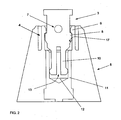
Figure 2 shows a cross section of a detail of the vehicular antenna that is the subject of the invention; -
Figure 3 is an exploded axonometric view of a construction variant of the vehicular antenna that is the subject of the invention; -
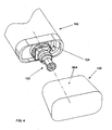
Figure 4 is a further exploded view of the vehicular antenna shown inFigure 3 ; -
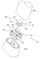
Figure 5 is an exploded axonometric view of a further construction variant of the vehicular antenna that is the subject of the invention; -
Figure 6 shows a detail of the construction variant shown inFigure 5 ; -
Figure 7 shows a detail of the vehicular antenna that is the subject of the invention in operation; -
Figure 8 shows a detail of the construction variant shown inFigure 3 in operation; -
Figure 9 shows a detail of the construction variant shown inFigure 5 in operation. - The vehicular antenna that is the subject of the invention is represented in
Figures 1 and2 , where it is indicated as a whole by 1 and where it can be observed that it comprises at least one projectingbody 2 for receiving/sending radio-frequency signals, provided with electric contact means 3 that can be snapped in and thus constrained to retainingmeans 4 present in thebase 5 of the antenna 1 according to a coupling direction X. - According to the invention, the lateral surface of the electric contact means 3 is provided with projecting
elements 7 that can be positioned in contact with theretaining means 4, saidretaining means 4 being intrinsecally compliant to the contact with the projectingelements 7 in order to allow the separation of the electric contact means 3 from the retainingmeans 4 when the projectingbody 2 is subjected to a torque that tends to set it rotating on a plane that is orthogonal to the coupling direction X. - It should be noted that the constraint created between the projecting
body 2 and thebase 5, besides being, advantageously, particularly stable, determines a certain mutual position between the projectingbody 2 and thebase 5, making it possible, still advantageously, to obtain the continuity of the external surface of the antenna 1 of the invention in the connection point, whatever the profile of the antenna 1. - It should also be noted that, according to a construction variant of the invention, the retaining means can be identified on the projecting body and the electric contact means can be identified on the base.
- It is obvious that said construction variant is totally analogous to the preferred embodiment of the invention described herein, so much that it is not illustrated and described in detail to avoid useless repetitions.
- According to a preferred embodiment of the invention described herein, the electric contact means 3 present, on their lateral surface,
friction areas 8 that, as shown also inFigure 2 , rest againstundercuts 9 present in theretaining means 4. - This advantageously makes it possible to obtain the constraint of the projecting
body 2 to thebase 5, a constraint that according to the invention is removable, as will be illustrated in greater detail below, through the rotary motion of the projectingbody 2 that forces the projectingelements 7 against theretaining means 4 in order to expand them as much as needed to release thefriction areas 8 from theundercuts 9. - In the preferred embodiment of the antenna 1 described herein, the projecting
body 2 is a rod, but this is not intended to represent a limitation for different embodiments of the invention according to which the projecting body can be a fin or any other element suited to receive/send radio-frequency signals. - As regards the electric contact means 3, they comprise a shaped
male element 10 arranged at the end of the projectingbody 2 that is coupled with a shapedfemale element 11 belonging to thebase 5. - In particular, the shaped
female element 11 is provided with aconical cavity 12 that houses at least the terminal section of the shapedmale element 10 in order to generate the electric contact. - For this purpose, both the shaped
male element 10 and the shapedfemale element 11 will be at least partially made of an electrically conductive material and furthermore, as can be seen in the figures, the shapedmale element 10 has acentral slot 13 that makes it elastically compliant in the axial directions. - This allows the shaped
male element 10 to penetrate completely theconical cavity 12 of the shapedfemale element 11 and to generate the desired electric contact. - As regards the retaining means 4, according to the preferred embodiment of the invention described herein they comprise two or more mainly
laminate elements 15 opposing each other and projecting from thebase 5 in the coupling direction X, in which theundercuts 9 mentioned above are defined. - According to the preferred embodiment of the invention described herein, said
laminate elements 15 are defined by curved surfaces with opposing cavities. - Said
laminate elements 15 are two and are provided withundercuts 9 constituted by anannular sector 16 protruding from the inner surface of thelaminate elements 15. - Accordingly, the
friction area 8 of the electric contact means 3 is constituted by a collar that projects from the lateral surface of the contact means 3 and that, during insertion, presents ashaping 17 shown in detail inFigure 2 that is such as to expand theretaining means 4, said means being elastically compliant, as already explained. - Once the electric contact means 3 have been inserted inside the retaining means 4, the same retaining means 4 can return to the rest position by carrying out the constraint described above between the
undercuts 9 and thefriction areas 8. - As regards the projecting means 7, according to the preferred embodiment of the invention described herein, they are constituted by at least one pin projecting in two directions that passes through the electric contact means 3 according to a direction Y orthogonal to the coupling direction X mentioned above.
- Furthermore, the
base 5 comprises at least onehousing 21 that serves to house a respective end of thepin 7 projecting in two directions. - The connection between the
pin 7 projecting in two directions and thehousing 21 advantageously makes it possible to avoid an excessive rotation of the projectingbody 2 that may cause the retaining means 4 to break due to the excessive stress to which the projectingelements 7 subject them. - In this regard, the coupling between the
pin 7 and thehousings 21 constitutes an end-of-stroke element suited to stop the rotation of the projectingbody 2 with respect to thebase 5. - Obviously, the description given above is not intended to represent a limitation for different embodiments of the invention according to which, for example, the retaining means are constituted by a higher number of laminate elements.
- An example of said different embodiment is represented in
Figure 3 where the antenna that is the subject of the invention is indicated as a whole by 100 and where it can be observed that thelaminate elements 115 are four. - Also in this case, the
undercuts 109 are constituted by an annular sector protruding from the inner surface of thelaminate elements 115. - As regards, on the other hand, the
projecting elements 107, these are constituted by aprismatic body 130 positioned above thefriction areas 108 and having at least onevertex 131 suited to be inserted between theretaining means 104. - In particular, all the
vertices 131 of theprismatic body 130 fit in the interspaces between thelaminate elements 115 of the retaining means 104 in such a way as to force laterally thesame laminate elements 115 when the projectingbody 102 is set rotating with respect to thebase 105. - Furthermore, also in this case there is an end-of-stroke element suited to stop the rotation, constituted by a
pin 123 that develops in the coupling direction X and that fits in a containingway 124 present on the projectingbody 102 and illustrated inFigure 4 . - It is evident that during the rotation of the
rod 102 with respect to thebase 105, thepin 123 comes into contact with the lateral surface of the containingway 124 and thus stops the rotary movement. - According to a further different embodiment of the invention, represented in
Figure 5 and indicated as a whole by 200, thelaminate elements 215 are constituted by plane surfaces opposing each other. - In this case, the
undercuts 209, as observed also in the detail ofFigures 6 and9 , are constituted by at least oneimpression 235 recessed in the inner surface of thelaminate elements 215. - In order to enhance the constraining action exerted by said
undercuts 209 on thefriction areas 208, a throughhole 236 is provided in thelaminate elements 215 and below theimpressions 235. - Furthermore, the
laminate elements 215 are provided with at least oneslot 237 that occupies at least one section of thelaminate elements 215 in width, in such a way as to make them elastically compliant as already explained. - According to said construction variant, the projecting
elements 207, constituted by aprismatic body 230 like in the previous case, present at least onevertex 231, constituting thefriction areas 208 shown inFigure 5 , and at least oneedge 232 arranged in contact with the retaining means 204 and in particular with the section of the retaining means 204 made elastically compliant by theslot 237. - In this case, advantageously, the coupling of the electric contact means 203 to the retaining means 204 takes place owing to the friction present between the
vertices 231 of theprismatic body 230 and the lower surface of theimpressions 235 at the height of the throughholes 236. - According to the explanation given above, the subject of the invention includes also a method for separating the projecting
body 2 of the antenna 1 from thebase 5. - In particular, in operating conditions the projecting
body 2 is snapped in and constrained to thebase 5, since the electric contact means 3, as previously shown, present somefriction areas 8 that rest againstundercuts 9 provided in the retaining means themselves. - This condition is obtained by coupling the projecting
body 2 to thebase 5 along the coupling direction X so that the particular configuration of thefriction areas 8 forces the retaining means 4 to expand elastically. - After the passage of the
friction areas 8, the retaining means 4 return to the rest position by constraining theundercuts 9 to thefriction areas 8. -
Figure 7 shows the electric contact means 3 when inserted in the retaining means 4 of thebase 5. - The separation method described above comprises two steps:
- rotating the electric contact means 3 with respect to the retaining means 4 on a rotation plane that is orthogonal to the coupling direction X in such a way as to release the
friction areas 8 from theundercuts 9; - removing the projecting
body 2 from thebase 5 through a movement in the coupling direction X. - According to the invention, this method is characterized in that the release of the
friction areas 8 form theundercuts 9 takes place due to the elastic deformation of at least one section of the retaining means 4. - In particular, the rotation, which in
Figure 8 is indicated as a counterclockwise rotation, makes the projectingelements 7 push on the sides of thelaminate elements 15 of the retaining means 4 and forces their expansion owing, for example, to their intrinsic compliance or to a compliance due to structural modifications of the laminate elements themselves. - The
housing 21, furthermore, avoids an excessive rotation of the projectingbody 2 that may damage thelaminate elements 15 due to excessive stress. - According to the different embodiment of the invention shown in
Figures 3 and4 , the release of the electric contact means 103 from the retaining means 104 takes place thanks to the stress generated on thelaminate elements 115 by thevertices 131 of theprismatic body 130 constituting the projectingelements 107 of the electric contact means 103. - In fact, as shown in
Figure 9 , the rotation of the projectingbody 102 with respect to thebase 105 generates, as a consequence, a force applied to the sides of thelaminate elements 115 by thevertices 131. - Said force causes the expansion of the
laminate elements 115 with the consequent release of thefriction areas 108 from theundercuts 109 shown inFigure 3 . - Also in this case, the
pin 123, shown inFigure 3 , cooperates with the containingway 124, shown inFigure 4 , to prevent an excessive rotation that may damage thelaminate elements 115. - The situation of the embodiment shown in
Figure 9 is slightly different. - In this case, as shown in
Figure 9 , when the projectingbody 202 is constrained to thebase 205, at least one pair ofopposite vertices 231 is arranged in correspondence with the throughholes 236 present in thelaminate elements 215 below theimpressions 235. - To obtain the release of said
vertices 231 from theimpressions 235, owing to the rotating movement of the projectingbody 202 theedges 232 arranged in contact with thelaminate elements 215 force the expansion of the sections of thelaminate elements 215 made compliant by theslots 237. - Said expansion allows the
prismatic body 230 to be arranged obliquely with respect to the initial position, so that itsvertices 231 come out of the throughholes 236 present below theimpressions 235, thus releasing the constraint. - In this case, it is thus possible to remove the projecting
body 202 from thebase 205 of theantenna 200. - According to this embodiment, the end-of-stroke element is constituted by the walls of the base 205 that prevent an excessive expansion of the sections of the
laminate elements 215 provided with theslots 237. - According to the above, both the vehicular antenna and the method for separating the projecting body of the vehicular antenna from the base achieve the set objects.
- In particular, the invention achieves the object to implement a method that allows the projecting body of a vehicular antenna to be separated from the respective base very quickly, without becoming a nuisance for the users.
- The invention also achieves the object to construct a vehicular antenna that allows the projecting body to be constrained to the base with no need for screw means.
- The invention also achieves the object to ensure that said constraint is particularly stable and that the construction of the antenna remains rather simple.
- The invention finally achieves the object to construct a vehicular antenna that ensures the perfect connection, without any superficial non-homogeneity, between the projecting body of the antenna and the base.
- During the construction phase, the vehicular antenna that is the subject of the invention may undergo further changes that, though not illustrated and described herein, shall nonetheless be covered by the present patent, provided that they come within the scope of the claims that follow.
- Where technical features mentioned in any claim are followed by reference signs, those reference sings have been included for the sole purpose of increasing the intelligibility of the claims and accordingly such reference signs do not have any limiting effect on the interpretation of each element identified by way of example by such reference signs.
Claims (26)
- Vehicular antenna (1; 100; 00) comprising at least as a first part one projecting body (2; 102) suitable for receiving/sending radiofrequency signals and as a second part a base (5; 105; 205), electric contact means (3; 103; 203) situated in one of the two parts comprising a shaped male element (10), a shaped female,element (11) and retaining means (4; 104; 204) situated in the other part, said shaped male element (10) matching said shaped female element (11) and said retaining means (4; 104; 204) being configured to realize a constraint of the snap-in type with the electric contact means (3; 103; 203) wherein said projecting body can be snapped in and constrained to the base (5; 105; 205) in a coupling direction (X) through the contact of friction areas (8; 108; 208) belonging to electric contact means (3; 103; 203) with undercuts (9; 109; 209) that can be identified on retaining means (4; 104; 204), characterized in that the lateral surface of said electric contact means (3; 103; 203) presents projecting elements (7; 107; 207) to be positioned in contact with said retaining means (4; 104; 204), wherein said retaining means (4; 104; 204) are compliant to the contact with said projecting elements (7; 107; 207) to allow for separation of said electric contact means (3; 103; 203) from said retaining means (4; 104; 204) releasing said friction areas (8; 108; 208) from said undercuts (9; 109; 209) through elastic deformation of at least one section of said retaining means (4; 104; 204) caused by said projecting elements (7; 107; 207) when said projecting body (2; 102) is subjected to a torque that tends to set it rotating on a plane that is orthogonal to said coupling direction (X).
- Antenna (1; 100; 200) according to claim 1), characterized in that said electric contact means (3; 103; 203) can be identified on said projecting body (2; 102) and said retaining means (4; 104; 204) can be identified on said base (5; 105; 205).
- Vehicular antenna (1; 100; 200) according to claim 1) or 2), characterized in that said shaped male element (10) is arranged at the end of said projecting body (2; 102) and matches with the shaped female element (11) belonging to said base (5; 105; 205).
- Vehicular antenna (1; 100) according to claim 3), characterized in that said shaped female element (11) is provided with a conical cavity (12) suited to receive at least one section of said shaped male element (10) in order to generate said electric contact.
- Vehicular antenna (1; 100; 200) according to any of the claims from 1) to 4), characterized in that said retaining means (4; 104; 204) comprise one or more mainly laminate elements (15; 115; 215) opposing one another and projecting from said base (5; 105; 205) in said coupling direction (X), in which said undercuts (9; 109; 209) are defined.
- Antenna according to claim 1), characterized in that said electric contact means can be identified on said base and said retaining means can be identified on said projecting body.
- Vehicular antenna according to claim 1) or 6), characterized in that said shaped female element is arranged at the end of said projecting body and matches with a shaped male element belonging to said base.
- Vehicular antenna according to claim 7), characterized in that said shaped female element is provided with a conical cavity suited to receive at least one section of said shaped male element in order to generate said electric contact.
- Vehicular antenna according to any of the claims from 6) to 8), characterized in that said retaining means comprise one or more mainly laminate elements opposing one another and projecting from said projecting body in said coupling direction, in which said undercuts are defined.
- Vehicular antenna (1; 100) according to claim 5) or 9), characterized in that said laminate elements (15; 115) are defined by curved surfaces with opposing concavities.
- Vehicular antenna (200) according to claim 5) or 9), characterized in that said laminate elements (215) are defined by opposing plane surfaces.
- Vehicular antenna (1; 100) according to claim 10), characterized in that said undercuts (9; 109) are constituted by an annular sector (16) projecting from the inner surface of said laminate elements (15; 115).
- Vehicular antenna (200) according to claim 11); characterized in that said undercuts (209) are constituted by at least one impression (235) recessed in the inner surface of said laminate elements (215).
- Vehicular antenna (200) according to claims 13), characterized in that said laminate elements (215) are provided with a through hole (236) below said impression (235).
- Vehicular antenna (200) according to claim 13) or 14), characterized in that said laminate elements (215) are provided each with at least one slot (237) that occupies at least one section of said laminate elements (215) in width.
- Vehicular antenna (1; 100; 200) according to any of the preceding claims, characterized in that said projecting body (2; 102) is a rod.
- Vehicular antenna (1) according to any of the claims from 1) to 16), characterized in that said projecting elements (7) are constituted by at least one pin projecting in two directions that passes through said electric contact means (3) in a direction (Y) that is orthogonal to said coupling direction (X).
- Vehicular antenna (1) according to claim 17), characterized in that it comprises at least one housing (21) suited to receive a corresponding end of said pin (7) projecting in two directions.
- Vehicular antenna (100) according to any of the claims from 1) to 16), characterized in that said projecting elements (107) are constituted by a prismatic body (130) positioned above said friction areas (108) and having at least one vertex (131) suited to be inserted in said retaining means (104).
- Vehicular antenna (200) according to any of the claims from 1) to 16), characterized in that said projecting elements (207) are constituted by a prismatic body (230) having at least one vertex (231) constituting said friction areas (208) and having at least one edge (232) arranged in contact with said retaining means (204).
- Vehicular antenna (1; 100; 200) according to any of the preceding claims, characterized in that it comprises an end-of-stroke element suited to stop the rotation of said projecting body (2; 102) with respect to said base (5; 105; 205).
- Vehicular antenna (100) according to claim 21), characterized in that said end-of-stroke element suited to stop the rotation comprises at least one pin (123) belonging to said base (105) and developing in said coupling direction (X), said pin (123) being suited to fit in a containing way (124) present on said projecting body (102).
- Method for separating the projecting body (2; 102) from the base (5; 105; 205) of the antenna (1; 100; 200) according to anyone of the claims 1)-22), said method including the following steps:- rotating said electric contact means (3; 103; 203) with respect to said retaining means (4; 104; 204) on a rotation plane that is orthogonal to said coupling direction (X) in such a way as to release said friction areas (8; 108; 208) from said undercuts (9; 109; 209);- removing said projecting body (2; 102) from said base (5; 105; 205) through a movement in said coupling direction (X),wherein said release of said friction areas (8; 108; 208) from said undercuts (9; 109; 209) takes place through elastic deformation of at least one section of said retaining means (4; 104; 204) and wherein said elastic deformation is obtained when said projecting body (2; 102) is subjected to a torque that tends to set it rotating on a plane that is orthogonal to said coupling direction (X) by forcing the projecting elements (7; 107; 207) belonging to the lateral surface of said electric contact means (3; 103; 203) against said section of said retaining means (4; 104; 204).
- Method according to claim 23), characterized in that said electric contact means (3; 103; 203) can be identified on said projecting body (2; 102) and said retaining means (4; 104; 204) can be identified on said base (5; 105; 205).
- Method according to claim 23), characterized in that said electric contact means can be identified on said base and said retaining means can be identified on said projecting body.
- Method according to any of the preceding claims, characterized in that said elastic deformation takes place due to the intrinsic compliance of said section of said retaining means (4; 104; 204).
Applications Claiming Priority (1)
| Application Number | Priority Date | Filing Date | Title |
|---|---|---|---|
| IT000358A ITVI20060358A1 (en) | 2006-12-20 | 2006-12-20 | METHOD OF SEPARATION OF A PROBLEM OF A ANTENNA FROM A BASE AND VEHICLE ANTENNA USING THIS METHOD |
Publications (2)
| Publication Number | Publication Date |
|---|---|
| EP1939977A1 EP1939977A1 (en) | 2008-07-02 |
| EP1939977B1 true EP1939977B1 (en) | 2009-08-12 |
Family
ID=37946699
Family Applications (1)
| Application Number | Title | Priority Date | Filing Date |
|---|---|---|---|
| EP07111343A Not-in-force EP1939977B1 (en) | 2006-12-20 | 2007-06-28 | Method for separating a projecting body of an antenna from a base and vehicular antenna using said method |
Country Status (4)
| Country | Link |
|---|---|
| EP (1) | EP1939977B1 (en) |
| AT (1) | ATE439689T1 (en) |
| DE (1) | DE602007001943D1 (en) |
| IT (1) | ITVI20060358A1 (en) |
Family Cites Families (4)
| Publication number | Priority date | Publication date | Assignee | Title |
|---|---|---|---|---|
| DE1655144A1 (en) * | 1968-02-29 | 1971-05-19 | Sihn Jr Kg Wilhelm | Fastening device for removable vehicle antennas |
| DE4005029C2 (en) | 1990-02-19 | 1994-08-11 | Hirschmann Richard Gmbh Co | Vehicle antenna |
| ITVI980153A1 (en) * | 1998-08-11 | 2000-02-11 | Massimo Calearo | ANTITHEFT ANTENNA |
| AU2001240999A1 (en) * | 2000-03-07 | 2001-09-17 | Galtronics Usa, Inc. | Antenna connector |
-
2006
- 2006-12-20 IT IT000358A patent/ITVI20060358A1/en unknown
-
2007
- 2007-06-28 DE DE602007001943T patent/DE602007001943D1/en active Active
- 2007-06-28 AT AT07111343T patent/ATE439689T1/en not_active IP Right Cessation
- 2007-06-28 EP EP07111343A patent/EP1939977B1/en not_active Not-in-force
Also Published As
| Publication number | Publication date |
|---|---|
| ITVI20060358A1 (en) | 2008-06-21 |
| EP1939977A1 (en) | 2008-07-02 |
| ATE439689T1 (en) | 2009-08-15 |
| DE602007001943D1 (en) | 2009-09-24 |
Similar Documents
| Publication | Publication Date | Title |
|---|---|---|
| EP2355553B1 (en) | An assembly comprising a male and a female plug member, a male plug member and a female plug member | |
| CN112242625B (en) | Connecting plug, forming method thereof, plug-in connector and connecting socket | |
| US5393239A (en) | Self-locking female electrical socket having automatic release mechanism | |
| KR100573969B1 (en) | Cable connector assembly | |
| CN101529668B (en) | Connector assembly for a cable having a radially facing conductive surface | |
| CN103606783A (en) | Male connector, female connector and connector component | |
| CN106450860A (en) | Pin with angled retention member | |
| US6100852A (en) | Anti-theft antenna | |
| US5645452A (en) | Connector housing | |
| KR100573970B1 (en) | Protrusion mating latch connector | |
| EP2973880B1 (en) | Method of manufacturing a housing and a lever | |
| EP1939977A1 (en) | Method for separating a projecting body of an antenna from a base and vehicular antenna using said method | |
| EP1284525A3 (en) | Plug type connector | |
| KR20110009902A (en) | Keycode Detachable Connector Unit | |
| US6206733B1 (en) | Connection block assembly for a waterproof switch | |
| EP0795937B1 (en) | Connector and connector kit | |
| US7112092B2 (en) | Coaxial cable coupler, especially an antenna coupler | |
| WO2019008062A1 (en) | Connector and connector assembly | |
| CN101010764A (en) | Connector element connection and method for production of a connection between installation breakers | |
| US5376023A (en) | Electric connector | |
| WO2015063475A1 (en) | Mechanical latching mechanism incorporating a spring clip | |
| EP0726616A2 (en) | A pin coupling for the connection of co-axial cables | |
| JP3840094B2 (en) | Connector for coaxial cable | |
| CN105379027A (en) | Locking apparatus for plug connectors | |
| CN222234024U (en) | A pre-grounded connector |
Legal Events
| Date | Code | Title | Description |
|---|---|---|---|
| PUAI | Public reference made under article 153(3) epc to a published international application that has entered the european phase |
Free format text: ORIGINAL CODE: 0009012 |
|
| AK | Designated contracting states |
Kind code of ref document: A1 Designated state(s): AT BE BG CH CY CZ DE DK EE ES FI FR GB GR HU IE IS IT LI LT LU LV MC MT NL PL PT RO SE SI SK TR |
|
| AX | Request for extension of the european patent |
Extension state: AL BA HR MK RS |
|
| GRAP | Despatch of communication of intention to grant a patent |
Free format text: ORIGINAL CODE: EPIDOSNIGR1 |
|
| 17P | Request for examination filed |
Effective date: 20081230 |
|
| AKX | Designation fees paid |
Designated state(s): AT BE BG CH CY CZ DE DK EE ES FI FR GB GR HU IE IS IT LI LT LU LV MC MT NL PL PT RO SE SI SK TR |
|
| GRAS | Grant fee paid |
Free format text: ORIGINAL CODE: EPIDOSNIGR3 |
|
| GRAA | (expected) grant |
Free format text: ORIGINAL CODE: 0009210 |
|
| AK | Designated contracting states |
Kind code of ref document: B1 Designated state(s): AT BE BG CH CY CZ DE DK EE ES FI FR GB GR HU IE IS IT LI LT LU LV MC MT NL PL PT RO SE SI SK TR |
|
| REG | Reference to a national code |
Ref country code: GB Ref legal event code: FG4D |
|
| REG | Reference to a national code |
Ref country code: CH Ref legal event code: EP |
|
| REG | Reference to a national code |
Ref country code: IE Ref legal event code: FG4D |
|
| REF | Corresponds to: |
Ref document number: 602007001943 Country of ref document: DE Date of ref document: 20090924 Kind code of ref document: P |
|
| LTIE | Lt: invalidation of european patent or patent extension |
Effective date: 20090812 |
|
| PG25 | Lapsed in a contracting state [announced via postgrant information from national office to epo] |
Ref country code: IS Free format text: LAPSE BECAUSE OF FAILURE TO SUBMIT A TRANSLATION OF THE DESCRIPTION OR TO PAY THE FEE WITHIN THE PRESCRIBED TIME-LIMIT Effective date: 20091212 Ref country code: ES Free format text: LAPSE BECAUSE OF FAILURE TO SUBMIT A TRANSLATION OF THE DESCRIPTION OR TO PAY THE FEE WITHIN THE PRESCRIBED TIME-LIMIT Effective date: 20091123 Ref country code: AT Free format text: LAPSE BECAUSE OF FAILURE TO SUBMIT A TRANSLATION OF THE DESCRIPTION OR TO PAY THE FEE WITHIN THE PRESCRIBED TIME-LIMIT Effective date: 20090812 Ref country code: SE Free format text: LAPSE BECAUSE OF FAILURE TO SUBMIT A TRANSLATION OF THE DESCRIPTION OR TO PAY THE FEE WITHIN THE PRESCRIBED TIME-LIMIT Effective date: 20090812 Ref country code: FI Free format text: LAPSE BECAUSE OF FAILURE TO SUBMIT A TRANSLATION OF THE DESCRIPTION OR TO PAY THE FEE WITHIN THE PRESCRIBED TIME-LIMIT Effective date: 20090812 Ref country code: LT Free format text: LAPSE BECAUSE OF FAILURE TO SUBMIT A TRANSLATION OF THE DESCRIPTION OR TO PAY THE FEE WITHIN THE PRESCRIBED TIME-LIMIT Effective date: 20090812 |
|
| NLV1 | Nl: lapsed or annulled due to failure to fulfill the requirements of art. 29p and 29m of the patents act | ||
| PG25 | Lapsed in a contracting state [announced via postgrant information from national office to epo] |
Ref country code: PL Free format text: LAPSE BECAUSE OF FAILURE TO SUBMIT A TRANSLATION OF THE DESCRIPTION OR TO PAY THE FEE WITHIN THE PRESCRIBED TIME-LIMIT Effective date: 20090812 Ref country code: SI Free format text: LAPSE BECAUSE OF FAILURE TO SUBMIT A TRANSLATION OF THE DESCRIPTION OR TO PAY THE FEE WITHIN THE PRESCRIBED TIME-LIMIT Effective date: 20090812 Ref country code: LV Free format text: LAPSE BECAUSE OF FAILURE TO SUBMIT A TRANSLATION OF THE DESCRIPTION OR TO PAY THE FEE WITHIN THE PRESCRIBED TIME-LIMIT Effective date: 20090812 Ref country code: NL Free format text: LAPSE BECAUSE OF FAILURE TO SUBMIT A TRANSLATION OF THE DESCRIPTION OR TO PAY THE FEE WITHIN THE PRESCRIBED TIME-LIMIT Effective date: 20090812 |
|
| PG25 | Lapsed in a contracting state [announced via postgrant information from national office to epo] |
Ref country code: BG Free format text: LAPSE BECAUSE OF FAILURE TO SUBMIT A TRANSLATION OF THE DESCRIPTION OR TO PAY THE FEE WITHIN THE PRESCRIBED TIME-LIMIT Effective date: 20091112 Ref country code: PT Free format text: LAPSE BECAUSE OF FAILURE TO SUBMIT A TRANSLATION OF THE DESCRIPTION OR TO PAY THE FEE WITHIN THE PRESCRIBED TIME-LIMIT Effective date: 20091212 |
|
| PG25 | Lapsed in a contracting state [announced via postgrant information from national office to epo] |
Ref country code: DK Free format text: LAPSE BECAUSE OF FAILURE TO SUBMIT A TRANSLATION OF THE DESCRIPTION OR TO PAY THE FEE WITHIN THE PRESCRIBED TIME-LIMIT Effective date: 20090812 Ref country code: CZ Free format text: LAPSE BECAUSE OF FAILURE TO SUBMIT A TRANSLATION OF THE DESCRIPTION OR TO PAY THE FEE WITHIN THE PRESCRIBED TIME-LIMIT Effective date: 20090812 Ref country code: EE Free format text: LAPSE BECAUSE OF FAILURE TO SUBMIT A TRANSLATION OF THE DESCRIPTION OR TO PAY THE FEE WITHIN THE PRESCRIBED TIME-LIMIT Effective date: 20090812 Ref country code: RO Free format text: LAPSE BECAUSE OF FAILURE TO SUBMIT A TRANSLATION OF THE DESCRIPTION OR TO PAY THE FEE WITHIN THE PRESCRIBED TIME-LIMIT Effective date: 20090812 |
|
| PG25 | Lapsed in a contracting state [announced via postgrant information from national office to epo] |
Ref country code: SK Free format text: LAPSE BECAUSE OF FAILURE TO SUBMIT A TRANSLATION OF THE DESCRIPTION OR TO PAY THE FEE WITHIN THE PRESCRIBED TIME-LIMIT Effective date: 20090812 |
|
| PLBE | No opposition filed within time limit |
Free format text: ORIGINAL CODE: 0009261 |
|
| STAA | Information on the status of an ep patent application or granted ep patent |
Free format text: STATUS: NO OPPOSITION FILED WITHIN TIME LIMIT |
|
| PG25 | Lapsed in a contracting state [announced via postgrant information from national office to epo] |
Ref country code: BE Free format text: LAPSE BECAUSE OF FAILURE TO SUBMIT A TRANSLATION OF THE DESCRIPTION OR TO PAY THE FEE WITHIN THE PRESCRIBED TIME-LIMIT Effective date: 20090812 |
|
| 26N | No opposition filed |
Effective date: 20100517 |
|
| PG25 | Lapsed in a contracting state [announced via postgrant information from national office to epo] |
Ref country code: GR Free format text: LAPSE BECAUSE OF FAILURE TO SUBMIT A TRANSLATION OF THE DESCRIPTION OR TO PAY THE FEE WITHIN THE PRESCRIBED TIME-LIMIT Effective date: 20091113 |
|
| PG25 | Lapsed in a contracting state [announced via postgrant information from national office to epo] |
Ref country code: MC Free format text: LAPSE BECAUSE OF NON-PAYMENT OF DUE FEES Effective date: 20100630 |
|
| PG25 | Lapsed in a contracting state [announced via postgrant information from national office to epo] |
Ref country code: IT Free format text: LAPSE BECAUSE OF NON-PAYMENT OF DUE FEES Effective date: 20100628 |
|
| PG25 | Lapsed in a contracting state [announced via postgrant information from national office to epo] |
Ref country code: MT Free format text: LAPSE BECAUSE OF FAILURE TO SUBMIT A TRANSLATION OF THE DESCRIPTION OR TO PAY THE FEE WITHIN THE PRESCRIBED TIME-LIMIT Effective date: 20090812 Ref country code: IE Free format text: LAPSE BECAUSE OF NON-PAYMENT OF DUE FEES Effective date: 20100628 |
|
| REG | Reference to a national code |
Ref country code: CH Ref legal event code: PL |
|
| GBPC | Gb: european patent ceased through non-payment of renewal fee |
Effective date: 20110628 |
|
| PG25 | Lapsed in a contracting state [announced via postgrant information from national office to epo] |
Ref country code: LI Free format text: LAPSE BECAUSE OF NON-PAYMENT OF DUE FEES Effective date: 20110630 Ref country code: CH Free format text: LAPSE BECAUSE OF NON-PAYMENT OF DUE FEES Effective date: 20110630 |
|
| PG25 | Lapsed in a contracting state [announced via postgrant information from national office to epo] |
Ref country code: GB Free format text: LAPSE BECAUSE OF NON-PAYMENT OF DUE FEES Effective date: 20110628 |
|
| PGFP | Annual fee paid to national office [announced via postgrant information from national office to epo] |
Ref country code: DE Payment date: 20120622 Year of fee payment: 6 |
|
| PG25 | Lapsed in a contracting state [announced via postgrant information from national office to epo] |
Ref country code: CY Free format text: LAPSE BECAUSE OF FAILURE TO SUBMIT A TRANSLATION OF THE DESCRIPTION OR TO PAY THE FEE WITHIN THE PRESCRIBED TIME-LIMIT Effective date: 20090812 |
|
| PGFP | Annual fee paid to national office [announced via postgrant information from national office to epo] |
Ref country code: FR Payment date: 20120705 Year of fee payment: 6 |
|
| PG25 | Lapsed in a contracting state [announced via postgrant information from national office to epo] |
Ref country code: HU Free format text: LAPSE BECAUSE OF FAILURE TO SUBMIT A TRANSLATION OF THE DESCRIPTION OR TO PAY THE FEE WITHIN THE PRESCRIBED TIME-LIMIT Effective date: 20100213 Ref country code: LU Free format text: LAPSE BECAUSE OF NON-PAYMENT OF DUE FEES Effective date: 20100628 |
|
| PGFP | Annual fee paid to national office [announced via postgrant information from national office to epo] |
Ref country code: IT Payment date: 20120611 Year of fee payment: 6 |
|
| PG25 | Lapsed in a contracting state [announced via postgrant information from national office to epo] |
Ref country code: TR Free format text: LAPSE BECAUSE OF FAILURE TO SUBMIT A TRANSLATION OF THE DESCRIPTION OR TO PAY THE FEE WITHIN THE PRESCRIBED TIME-LIMIT Effective date: 20090812 |
|
| REG | Reference to a national code |
Ref country code: FR Ref legal event code: ST Effective date: 20140228 |
|
| REG | Reference to a national code |
Ref country code: DE Ref legal event code: R119 Ref document number: 602007001943 Country of ref document: DE Effective date: 20140101 |
|
| PG25 | Lapsed in a contracting state [announced via postgrant information from national office to epo] |
Ref country code: DE Free format text: LAPSE BECAUSE OF NON-PAYMENT OF DUE FEES Effective date: 20140101 |
|
| PG25 | Lapsed in a contracting state [announced via postgrant information from national office to epo] |
Ref country code: IT Free format text: LAPSE BECAUSE OF NON-PAYMENT OF DUE FEES Effective date: 20130628 Ref country code: FR Free format text: LAPSE BECAUSE OF NON-PAYMENT OF DUE FEES Effective date: 20130701 |