EP1939924A2 - Electron beam physical vapor deposition apparatus and processes - Google Patents
Electron beam physical vapor deposition apparatus and processes Download PDFInfo
- Publication number
- EP1939924A2 EP1939924A2 EP07254889A EP07254889A EP1939924A2 EP 1939924 A2 EP1939924 A2 EP 1939924A2 EP 07254889 A EP07254889 A EP 07254889A EP 07254889 A EP07254889 A EP 07254889A EP 1939924 A2 EP1939924 A2 EP 1939924A2
- Authority
- EP
- European Patent Office
- Prior art keywords
- target
- height
- optical sensor
- electron
- light intensity
- Prior art date
- Legal status (The legal status is an assumption and is not a legal conclusion. Google has not performed a legal analysis and makes no representation as to the accuracy of the status listed.)
- Withdrawn
Links
- 238000005328 electron beam physical vapour deposition Methods 0.000 title claims abstract description 54
- 238000000034 method Methods 0.000 title claims abstract description 16
- 230000008569 process Effects 0.000 title claims abstract description 15
- 230000003287 optical effect Effects 0.000 claims abstract description 35
- 238000001704 evaporation Methods 0.000 claims abstract description 12
- 230000008859 change Effects 0.000 claims abstract description 8
- 238000012544 monitoring process Methods 0.000 claims abstract description 7
- 238000003475 lamination Methods 0.000 claims description 12
- 230000008020 evaporation Effects 0.000 claims description 6
- 230000007246 mechanism Effects 0.000 claims description 5
- 238000004519 manufacturing process Methods 0.000 claims description 3
- 239000000758 substrate Substances 0.000 claims description 3
- 239000010453 quartz Substances 0.000 claims description 2
- VYPSYNLAJGMNEJ-UHFFFAOYSA-N silicon dioxide Inorganic materials O=[Si]=O VYPSYNLAJGMNEJ-UHFFFAOYSA-N 0.000 claims description 2
- 230000003213 activating effect Effects 0.000 claims 2
- 230000003247 decreasing effect Effects 0.000 claims 2
- 238000001914 filtration Methods 0.000 claims 2
- 229910000883 Ti6Al4V Inorganic materials 0.000 description 10
- 238000001000 micrograph Methods 0.000 description 8
- 230000004044 response Effects 0.000 description 4
- 239000000126 substance Substances 0.000 description 4
- XAGFODPZIPBFFR-UHFFFAOYSA-N aluminium Chemical compound [Al] XAGFODPZIPBFFR-UHFFFAOYSA-N 0.000 description 3
- 229910052782 aluminium Inorganic materials 0.000 description 3
- 238000010894 electron beam technology Methods 0.000 description 3
- 238000005259 measurement Methods 0.000 description 3
- 230000000087 stabilizing effect Effects 0.000 description 3
- 230000005540 biological transmission Effects 0.000 description 1
- 239000011248 coating agent Substances 0.000 description 1
- 238000000576 coating method Methods 0.000 description 1
- 238000000151 deposition Methods 0.000 description 1
- 238000010410 dusting Methods 0.000 description 1
- 230000001747 exhibiting effect Effects 0.000 description 1
- 238000002474 experimental method Methods 0.000 description 1
- 239000002657 fibrous material Substances 0.000 description 1
- 239000012467 final product Substances 0.000 description 1
- 230000004907 flux Effects 0.000 description 1
- 239000007788 liquid Substances 0.000 description 1
- 238000012986 modification Methods 0.000 description 1
- 230000004048 modification Effects 0.000 description 1
- 230000006641 stabilisation Effects 0.000 description 1
- 238000011105 stabilization Methods 0.000 description 1
Images




Classifications
-
- H—ELECTRICITY
- H01—ELECTRIC ELEMENTS
- H01J—ELECTRIC DISCHARGE TUBES OR DISCHARGE LAMPS
- H01J37/00—Discharge tubes with provision for introducing objects or material to be exposed to the discharge, e.g. for the purpose of examination or processing thereof
- H01J37/30—Electron-beam or ion-beam tubes for localised treatment of objects
- H01J37/305—Electron-beam or ion-beam tubes for localised treatment of objects for casting, melting, evaporating, or etching
- H01J37/3053—Electron-beam or ion-beam tubes for localised treatment of objects for casting, melting, evaporating, or etching for evaporating or etching
-
- C—CHEMISTRY; METALLURGY
- C23—COATING METALLIC MATERIAL; COATING MATERIAL WITH METALLIC MATERIAL; CHEMICAL SURFACE TREATMENT; DIFFUSION TREATMENT OF METALLIC MATERIAL; COATING BY VACUUM EVAPORATION, BY SPUTTERING, BY ION IMPLANTATION OR BY CHEMICAL VAPOUR DEPOSITION, IN GENERAL; INHIBITING CORROSION OF METALLIC MATERIAL OR INCRUSTATION IN GENERAL
- C23C—COATING METALLIC MATERIAL; COATING MATERIAL WITH METALLIC MATERIAL; SURFACE TREATMENT OF METALLIC MATERIAL BY DIFFUSION INTO THE SURFACE, BY CHEMICAL CONVERSION OR SUBSTITUTION; COATING BY VACUUM EVAPORATION, BY SPUTTERING, BY ION IMPLANTATION OR BY CHEMICAL VAPOUR DEPOSITION, IN GENERAL
- C23C14/00—Coating by vacuum evaporation, by sputtering or by ion implantation of the coating forming material
- C23C14/22—Coating by vacuum evaporation, by sputtering or by ion implantation of the coating forming material characterised by the process of coating
- C23C14/24—Vacuum evaporation
- C23C14/246—Replenishment of source material
-
- C—CHEMISTRY; METALLURGY
- C23—COATING METALLIC MATERIAL; COATING MATERIAL WITH METALLIC MATERIAL; CHEMICAL SURFACE TREATMENT; DIFFUSION TREATMENT OF METALLIC MATERIAL; COATING BY VACUUM EVAPORATION, BY SPUTTERING, BY ION IMPLANTATION OR BY CHEMICAL VAPOUR DEPOSITION, IN GENERAL; INHIBITING CORROSION OF METALLIC MATERIAL OR INCRUSTATION IN GENERAL
- C23C—COATING METALLIC MATERIAL; COATING MATERIAL WITH METALLIC MATERIAL; SURFACE TREATMENT OF METALLIC MATERIAL BY DIFFUSION INTO THE SURFACE, BY CHEMICAL CONVERSION OR SUBSTITUTION; COATING BY VACUUM EVAPORATION, BY SPUTTERING, BY ION IMPLANTATION OR BY CHEMICAL VAPOUR DEPOSITION, IN GENERAL
- C23C14/00—Coating by vacuum evaporation, by sputtering or by ion implantation of the coating forming material
- C23C14/22—Coating by vacuum evaporation, by sputtering or by ion implantation of the coating forming material characterised by the process of coating
- C23C14/24—Vacuum evaporation
- C23C14/28—Vacuum evaporation by wave energy or particle radiation
- C23C14/30—Vacuum evaporation by wave energy or particle radiation by electron bombardment
-
- C—CHEMISTRY; METALLURGY
- C23—COATING METALLIC MATERIAL; COATING MATERIAL WITH METALLIC MATERIAL; CHEMICAL SURFACE TREATMENT; DIFFUSION TREATMENT OF METALLIC MATERIAL; COATING BY VACUUM EVAPORATION, BY SPUTTERING, BY ION IMPLANTATION OR BY CHEMICAL VAPOUR DEPOSITION, IN GENERAL; INHIBITING CORROSION OF METALLIC MATERIAL OR INCRUSTATION IN GENERAL
- C23C—COATING METALLIC MATERIAL; COATING MATERIAL WITH METALLIC MATERIAL; SURFACE TREATMENT OF METALLIC MATERIAL BY DIFFUSION INTO THE SURFACE, BY CHEMICAL CONVERSION OR SUBSTITUTION; COATING BY VACUUM EVAPORATION, BY SPUTTERING, BY ION IMPLANTATION OR BY CHEMICAL VAPOUR DEPOSITION, IN GENERAL
- C23C14/00—Coating by vacuum evaporation, by sputtering or by ion implantation of the coating forming material
- C23C14/22—Coating by vacuum evaporation, by sputtering or by ion implantation of the coating forming material characterised by the process of coating
- C23C14/54—Controlling or regulating the coating process
- C23C14/542—Controlling the film thickness or evaporation rate
- C23C14/543—Controlling the film thickness or evaporation rate using measurement on the vapor source
-
- H—ELECTRICITY
- H01—ELECTRIC ELEMENTS
- H01J—ELECTRIC DISCHARGE TUBES OR DISCHARGE LAMPS
- H01J37/00—Discharge tubes with provision for introducing objects or material to be exposed to the discharge, e.g. for the purpose of examination or processing thereof
- H01J37/30—Electron-beam or ion-beam tubes for localised treatment of objects
- H01J37/3002—Details
- H01J37/3005—Observing the objects or the point of impact on the object
-
- H—ELECTRICITY
- H01—ELECTRIC ELEMENTS
- H01J—ELECTRIC DISCHARGE TUBES OR DISCHARGE LAMPS
- H01J37/00—Discharge tubes with provision for introducing objects or material to be exposed to the discharge, e.g. for the purpose of examination or processing thereof
- H01J37/30—Electron-beam or ion-beam tubes for localised treatment of objects
- H01J37/304—Controlling tubes by information coming from the objects or from the beam, e.g. correction signals
-
- H—ELECTRICITY
- H01—ELECTRIC ELEMENTS
- H01J—ELECTRIC DISCHARGE TUBES OR DISCHARGE LAMPS
- H01J2237/00—Discharge tubes exposing object to beam, e.g. for analysis treatment, etching, imaging
- H01J2237/248—Components associated with the control of the tube
- H01J2237/2482—Optical means
-
- H—ELECTRICITY
- H01—ELECTRIC ELEMENTS
- H01J—ELECTRIC DISCHARGE TUBES OR DISCHARGE LAMPS
- H01J2237/00—Discharge tubes exposing object to beam, e.g. for analysis treatment, etching, imaging
- H01J2237/30—Electron or ion beam tubes for processing objects
- H01J2237/304—Controlling tubes
- H01J2237/30455—Correction during exposure
Definitions
- the invention relates to electron beam physical vapor deposition apparatus and, more particularly, to independent spatial position stabilization of a target in an electron beam physical vapor deposition apparatus.
- Chemical variations, e.g., lamination, across the cross-section of multi-component condensates are one of the main problems encountered when utilizing Electron-Beam Physical Vapor Deposition (EB-PVD) techniques. These chemical variations are caused by instability in EB-PVD process parameters. For instance, one main parameter whose instability can cause such significant chemical variations is the relative level of the molten pool within the EB-PVD chamber. Theoretically, when the molten pool level is maintained at a fixed height throughout the EB-PVD process, lamination may be significantly reduced or eliminated. However, in current EB-PVD apparatus, the molten pool level is maintained manually by the EB-PVD operator. As a result, the relative level of the molten pool remains a potentially instable operating parameter.
- EB-PVD Electron-Beam Physical Vapor Deposition
- process for adjusting a feed rate in an electron-beam physical vapor deposition apparatus broadly comprises positioning a target at a first height within a chamber of an electron-beam physical vapor deposition apparatus; feeding the target at a rate into a beam of electrons generated by an electron gun of the electron-beam physical vapor deposition apparatus; evaporating the target with the beam of electrons; monitoring the first height by measuring a difference between a first light intensity and a second light intensity of at least one image of the target using an optical sensor disposed proximate to the chamber; determining a change in the first height; and adjusting a target feed rate.
- an electron beam physical vapor deposition apparatus broadly comprises a chamber housing the following: a target station; means for moving the target station; and a window; an optical sensor disposed in connection with the chamber and proximate to the window, wherein the optical sensor comprises means for measuring a difference between a first light intensity and a second light intensity of at least one image of a target; an electron gun disposed in connection with the chamber; and an electron module connected to the optical sensor and the means for moving the target station.
- a process for manufacturing multi-component condensates free of lamination using an electron-beam physical vapor deposition apparatus broadly comprises positioning a multi-component target at a first height within a chamber of an electron-beam physical vapor deposition apparatus; feeding the multi-component target at a rate into a beam of electrons generated by an electron gun of the electron-beam physical vapor deposition apparatus; evaporating the multi-component target with the beam of electrons into at least a first component evaporant and a second component evaporant; monitoring the first height by measuring a difference between a first light intensity and a second light intensity of at least one image of the multi-component target using an optical sensor disposed proximate to the chamber; determining a change in the first height; adjusting a multi-component target feed rate to evenly deposit the first component evaporant and the second component evaporant upon a substrate; and forming a multi-component condensate free of lamination.
- the EBPVD 10 generally includes a chamber 12 having a window 14 that houses a target station 16 disposed in connection with a means for moving the target station 18 having a power supply (not shown) and an actuation mechanism (not shown).
- An electron module 20 may be disposed outside the exterior of the chamber 12 and in connection with the means for moving the target station 18.
- An optical sensor 22 may be disposed proximate to the window 14 and in connection with the chamber 12. More particularly, the optical sensor 22 may be mounted externally to the chamber 12 and disposed against the window 14.
- the window 14 may comprise a quartz window having a diameter of about 30 millimeters (mm) to about 40 mm, or about 30 mm to about 35 mm, and a thickness of about 4 mm to about 10 mm, or about 6 mm to about 8 mm.
- the window 14 may also include a fibrous material (not shown) disposed upon its surface within the chamber 12 in amount sufficient to prevent the evaporated coating flux from depositing upon the window 14.
- the target station 16 may be a receptacle designed to hold the target being evaporated while providing a line-of-sight for the optical sensor to the surface of the target.
- the optical sensor 22 may comprise a gas dynamic filter 36, a focusing lens 38, a separating prism 40, and a first photodetector 41 and a second photodetector 43, each connected to a preamplifier 44.
- the gas dynamic filter 36 may be a substantially tubular structure having a grid disposed therein. The structure may be about 150 mm in length with an internal diameter of about 25 mm. The grid disposed within the structure may possess a mesh thickness of about 0.1 mm to about 0.15 mm.
- the gas dynamic filter 36 may provide a filter optical transmission of about 0.02 nm to about 0.05 nm during the course of evaporating at least a target of one (1) meter in length.
- the gas dynamic filter 36 and focusing lens 38 are coupled together and mounted to an exterior surface of the chamber 12.
- the gas dynamic filter 36 is positioned against the window 14 of the chamber 12 at an angle of about 3 degrees to about 7 degrees outward from the exterior surface of chamber 12 and in the line-of-sight of the target station 16.
- the focusing lens 38 may be any one of a number of focusing lenses known to one of ordinary skill in the art.
- the focusing lens 38 may be about 29 millimeters to about 30 millimeters in diameter, or about 29.5 mm to about 29.9 mm in diameter, or about 29.8 mm to about 29.9 mm in diameter, or about 29.9 mm in diameter, and have a focal distance of about 45 mm to about 55 mm, or about 49 mm to about 51 mm, or about 50 mm.
- the separating prism 40 may be any one of a number of separating prisms as known to one of ordinary skill in the art, and preferably is a 100% reflecting prism with a right angle at the apex and having a base size of about 10 mm by about 10 mm located within a hollow rectangle of about 30 mm by about 30 mm by about 20 mm.
- Each photodetector 41, 43 may be disposed within a vertical plane at opposing sides of the separating prism 40.
- the optical sensor 22 captures at least one image of the target within the target station 16 through the window 14.
- the gas dynamic filter 36 as known to one of ordinary skill in the art prevents dusting of the window 14 during the target evaporation process.
- the focusing lens 38 reduces the image passing through the window 14 and gas dynamic filter 36, and projects the image upon the apex of the separating prism 40.
- the separating prism 40 reflects a reflected image of the original image upon a first photodetector 41 and also refracts a refracted image of the original image upon a second photodetector 43.
- Each photodetector 41, 43 measures the intensity of light of the reflected image and the intensity of light of the refracted image.
- the difference in intensity or absence of a difference in intensity is registered and displayed by the preamplifier 44.
- the difference in intensity or absence of a difference in intensity is also communicated as at least one output signal from the optical sensor 22 to the electron module 20.
- the difference in intensity or absence of a difference in intensity may be determined by comparing the light intensity measurements of the photodetectors 41, 43.
- the output signal produced by the optical sensor 22, and based upon the difference in intensity, indicates whether the height of the target station 16 is higher or lower than an optimal height required for stabilizing the target surface and optimal evaporation of the target. If the light intensity measurements of each image are equal, the optical sensor 22 outputs a signal equal to zero (0). This indicates the two images of the target within the target station 16 are the same, and the height of the target station remains constant and unchanged.
- the surface of the molten liquid contained within the target station is the point at which the height is measured.
- the system will raise the target station 16 and in turn increase the feeding rate, that is, evaporation, of the target by the electron beam of the EB-PVD apparatus.
- the second photodetector 43 measures a light intensity value less than that of the first photodetector 41, then the height of the target station 16 is higher than an optimal height required for stabilizing the target surface and optimal evaporation of the target. In response, the system will lower the target station 16 and in turn reduce the feeding rate of the target by the electron beam of the EB-PVD apparatus.
- the electron module 20 is designed to amplify the output signal(s) generated by the optical sensor 22, interpret and translate the signal(s) to correspond to the height of the target station 16, and adjust the height of the target station 16 in response to these amplified output signals.
- the electron module 20 may comprise a power supply 24, a driving generator 26, an amplifier 28, a pulse-width modulator 30, and a mechanism power supply 33 for supplying power to an integrator 32 and the means for moving the target station 18.
- the amplifier 28 receives the output signal from the optical sensor 22.
- the amplifier 28 increases the output signal from about -20 decibels (dB) to about 20dB, and provides the amplified output signal to the pulse-width modulator 30.
- the pulse-width modulator 30 may be utilized to control the supply of the amplified output signal, that is, suppresses the current flow, to the galvanic isolator 32.
- the galvanic isolator 32 serves to isolate functional sections of the electrical system of the electron module 20.
- galvanic isolator 32 may be designed to electrically isolate the optical sensor circuitry shown in FIG. 3 from the rest of the system.
- the means for moving the target station 18 receives the output signal and moves the surface of the target within the target station 16 upward or downward at an angle perpendicular to the floor 48 of the chamber 12.
- the means for moving the target station 18 may be powered using the mechanism power supply 33 of the electron module 20.
- the means for moving the target station 18 may be any mechanism capable of moving the target station in the aforementioned directions at a rate of at least 0.2 mm per second to about 0.4 mm per second.
- the driving generator 26 may be any driving generator capable of operating at a frequency of about 9 kHz to about 10 kHz as known to one of ordinary skill in the art.
- the power supply 24 may be any power supply capable of providing about 10,000 volts (V), or 10 kV, of power as known to one of ordinary skill in the art.
- a multi-component target may be positioned at a first height within a chamber of the electron-beam physical vapor deposition apparatus.
- the multi-component target may be fed at a rate into a beam of electrons generated by the electron gun.
- the multi-component target may be evaporated into at least a first component evaporant and a second component evaporant.
- the first height of the multi-component target may be monitored using the optical sensor by measuring a difference between a first light intensity and a second light intensity of the images.
- the means for moving the target station may actuate the target station and in turn adjust the multi-component target feed rate to evenly deposit the first component evaporant and the second component evaporant upon a substrate and prevent lamination from occurring.
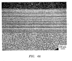
- FIG. 4 a pair of microphotographs taken at a magnification of 100x and at a magnification of 500x, respectively, of Ti-6Al-4V EBPVD condensate are shown.
- the Ti-6Al-4V EBPVD condensate of FIG. 4 were produced using an electron beam physical vapor deposition apparatus of the prior art.
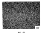
- FIG. 5 a pair of microphotographs taken at a magnification of 100x and a magnification of 500x resolution, respectively, of Ti-6Al-4V EBPVD condensate are shown.
- the Ti-6Al-4V EBPVD condensate of FIG. 5 was produced using an electron beam physical vapor deposition apparatus of the present invention.
- the Ti-6Al-4V EBPVD condensate exhibits layers enriched in aluminum, that is, lamination.
- the bright bands are the aluminum enriched layers exhibiting an aluminum content of approximately 11-12 wt.%.
- the Ti-6Al-4V EBPVD condensate shown in the microphotograph of FIG. 5 exhibits a highly uniform chemical composition across its cross-section, indicating lamination is practically absent. Lamination of the final product is counteracted by automatically monitoring the pool level using the Pool Level Closed Loop Control (PLCLC) system described herein.
Landscapes
- Chemical & Material Sciences (AREA)
- Engineering & Computer Science (AREA)
- Organic Chemistry (AREA)
- Materials Engineering (AREA)
- Mechanical Engineering (AREA)
- Metallurgy (AREA)
- Chemical Kinetics & Catalysis (AREA)
- Analytical Chemistry (AREA)
- Physics & Mathematics (AREA)
- Plasma & Fusion (AREA)
- Health & Medical Sciences (AREA)
- Toxicology (AREA)
- Physical Vapour Deposition (AREA)
Abstract
Description
- The invention relates to electron beam physical vapor deposition apparatus and, more particularly, to independent spatial position stabilization of a target in an electron beam physical vapor deposition apparatus.
- Chemical variations, e.g., lamination, across the cross-section of multi-component condensates are one of the main problems encountered when utilizing Electron-Beam Physical Vapor Deposition (EB-PVD) techniques. These chemical variations are caused by instability in EB-PVD process parameters. For instance, one main parameter whose instability can cause such significant chemical variations is the relative level of the molten pool within the EB-PVD chamber. Theoretically, when the molten pool level is maintained at a fixed height throughout the EB-PVD process, lamination may be significantly reduced or eliminated. However, in current EB-PVD apparatus, the molten pool level is maintained manually by the EB-PVD operator. As a result, the relative level of the molten pool remains a potentially instable operating parameter.
- Therefore, there exists a need for an EB-PVD apparatus equipped with an independent system designed to monitor and maintain a constant relative level of the molten pool within the EB-PVD chamber.
- In accordance with one aspect of the present invention, process for adjusting a feed rate in an electron-beam physical vapor deposition apparatus broadly comprises positioning a target at a first height within a chamber of an electron-beam physical vapor deposition apparatus; feeding the target at a rate into a beam of electrons generated by an electron gun of the electron-beam physical vapor deposition apparatus; evaporating the target with the beam of electrons; monitoring the first height by measuring a difference between a first light intensity and a second light intensity of at least one image of the target using an optical sensor disposed proximate to the chamber; determining a change in the first height; and adjusting a target feed rate.
- In accordance with another aspect of the present invention, an electron beam physical vapor deposition apparatus broadly comprises a chamber housing the following: a target station; means for moving the target station; and a window; an optical sensor disposed in connection with the chamber and proximate to the window, wherein the optical sensor comprises means for measuring a difference between a first light intensity and a second light intensity of at least one image of a target; an electron gun disposed in connection with the chamber; and an electron module connected to the optical sensor and the means for moving the target station.
- In accordance with yet another aspect of the present invention, a process for manufacturing multi-component condensates free of lamination using an electron-beam physical vapor deposition apparatus broadly comprises positioning a multi-component target at a first height within a chamber of an electron-beam physical vapor deposition apparatus; feeding the multi-component target at a rate into a beam of electrons generated by an electron gun of the electron-beam physical vapor deposition apparatus; evaporating the multi-component target with the beam of electrons into at least a first component evaporant and a second component evaporant; monitoring the first height by measuring a difference between a first light intensity and a second light intensity of at least one image of the multi-component target using an optical sensor disposed proximate to the chamber; determining a change in the first height; adjusting a multi-component target feed rate to evenly deposit the first component evaporant and the second component evaporant upon a substrate; and forming a multi-component condensate free of lamination.
- The details of one or more embodiments of the invention are set forth in the accompanying drawings and the description below. Other features and advantages of the invention will be apparent from the description and drawings, and from the claims.
-
-
FIG. 1 is a representation of an electron beam physical vapor deposition apparatus of the present invention; -
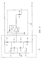
FIG. 2 is a representation of a flow chart of an electron module for use with the electron beam physical vapor deposition apparatus ofFIG. 1 ; -
FIG. 3 is a representation of a schematic of a sensor for use with the electron beam physical vapor deposition apparatus ofFIG. 1 ; -
FIG. 4A is a microphotograph taken at a magnification of 100x of a Ti-6Al-4V EBPVD condensate obtained with an electron beam physical vapor deposition apparatus of the prior art; -
FIG. 4B is a microphotograph taken at a magnification of 500x of a Ti-6Al-4V EBPVD condensate obtained with an electron beam physical vapor deposition apparatus of the prior art; -
FIG. 5A is a microphotograph taken at a magnification of 100x of a Ti-6Al-4V EBPVD condensate obtained with an electron beam physical vapor deposition apparatus of the present invention; and -
FIG. 5B is a microphotograph taken at a magnification of 500x of a Ti-6Al-4V EBPVD condensate obtained with an electron beam physical vapor deposition apparatus of the present invention. - Like reference numbers and designations in the various drawings indicate like elements.
- Referring now to
FIG. 1 , a representation of an electron beam physical vapor deposition apparatus 10 (hereinafter "EBPVD 10") of the present invention is shown. The EBPVD 10 generally includes achamber 12 having awindow 14 that houses atarget station 16 disposed in connection with a means for moving thetarget station 18 having a power supply (not shown) and an actuation mechanism (not shown). Anelectron module 20 may be disposed outside the exterior of thechamber 12 and in connection with the means for moving thetarget station 18. Anoptical sensor 22 may be disposed proximate to thewindow 14 and in connection with thechamber 12. More particularly, theoptical sensor 22 may be mounted externally to thechamber 12 and disposed against thewindow 14. Thewindow 14 may comprise a quartz window having a diameter of about 30 millimeters (mm) to about 40 mm, or about 30 mm to about 35 mm, and a thickness of about 4 mm to about 10 mm, or about 6 mm to about 8 mm. In addition, thewindow 14 may also include a fibrous material (not shown) disposed upon its surface within thechamber 12 in amount sufficient to prevent the evaporated coating flux from depositing upon thewindow 14. Thetarget station 16 may be a receptacle designed to hold the target being evaporated while providing a line-of-sight for the optical sensor to the surface of the target. - The
optical sensor 22 may comprise a gas dynamic filter 36, a focusing lens 38, aseparating prism 40, and afirst photodetector 41 and asecond photodetector 43, each connected to apreamplifier 44. The gas dynamic filter 36 may be a substantially tubular structure having a grid disposed therein. The structure may be about 150 mm in length with an internal diameter of about 25 mm. The grid disposed within the structure may possess a mesh thickness of about 0.1 mm to about 0.15 mm. The gas dynamic filter 36 may provide a filter optical transmission of about 0.02 nm to about 0.05 nm during the course of evaporating at least a target of one (1) meter in length. - The gas dynamic filter 36 and focusing lens 38 are coupled together and mounted to an exterior surface of the
chamber 12. Preferably, the gas dynamic filter 36 is positioned against thewindow 14 of thechamber 12 at an angle of about 3 degrees to about 7 degrees outward from the exterior surface ofchamber 12 and in the line-of-sight of thetarget station 16. The focusing lens 38 may be any one of a number of focusing lenses known to one of ordinary skill in the art. Preferably, the focusing lens 38 may be about 29 millimeters to about 30 millimeters in diameter, or about 29.5 mm to about 29.9 mm in diameter, or about 29.8 mm to about 29.9 mm in diameter, or about 29.9 mm in diameter, and have a focal distance of about 45 mm to about 55 mm, or about 49 mm to about 51 mm, or about 50 mm. The separatingprism 40 may be any one of a number of separating prisms as known to one of ordinary skill in the art, and preferably is a 100% reflecting prism with a right angle at the apex and having a base size of about 10 mm by about 10 mm located within a hollow rectangle of about 30 mm by about 30 mm by about 20 mm. Eachphotodetector prism 40. - The
optical sensor 22 captures at least one image of the target within thetarget station 16 through thewindow 14. The gas dynamic filter 36 as known to one of ordinary skill in the art prevents dusting of thewindow 14 during the target evaporation process. The focusing lens 38 reduces the image passing through thewindow 14 and gas dynamic filter 36, and projects the image upon the apex of the separatingprism 40. Theseparating prism 40 reflects a reflected image of the original image upon afirst photodetector 41 and also refracts a refracted image of the original image upon asecond photodetector 43. Eachphotodetector preamplifier 44. In addition, the difference in intensity or absence of a difference in intensity is also communicated as at least one output signal from theoptical sensor 22 to theelectron module 20. - The difference in intensity or absence of a difference in intensity may be determined by comparing the light intensity measurements of the
photodetectors optical sensor 22, and based upon the difference in intensity, indicates whether the height of thetarget station 16 is higher or lower than an optimal height required for stabilizing the target surface and optimal evaporation of the target. If the light intensity measurements of each image are equal, theoptical sensor 22 outputs a signal equal to zero (0). This indicates the two images of the target within thetarget station 16 are the same, and the height of the target station remains constant and unchanged. When referring to the height of thetarget station 16, the surface of the molten liquid contained within the target station is the point at which the height is measured. - If the light intensity measurements of each image are not equal, this indicates the two images of the target are not the same, and the height of the target station has changed. If the
second photodetector 43 measures a light intensity value greater than that of thefirst photodetector 41, then the height of thetarget station 16 is lower than an optimal height required for stabilizing the target surface and optimal evaporation of the target. In response, the system will raise thetarget station 16 and in turn increase the feeding rate, that is, evaporation, of the target by the electron beam of the EB-PVD apparatus. If thesecond photodetector 43 measures a light intensity value less than that of thefirst photodetector 41, then the height of thetarget station 16 is higher than an optimal height required for stabilizing the target surface and optimal evaporation of the target. In response, the system will lower thetarget station 16 and in turn reduce the feeding rate of the target by the electron beam of the EB-PVD apparatus. - Referring now to
FIGS. 2 and3 , theelectron module 20 is designed to amplify the output signal(s) generated by theoptical sensor 22, interpret and translate the signal(s) to correspond to the height of thetarget station 16, and adjust the height of thetarget station 16 in response to these amplified output signals. Theelectron module 20 may comprise apower supply 24, adriving generator 26, anamplifier 28, a pulse-width modulator 30, and amechanism power supply 33 for supplying power to anintegrator 32 and the means for moving thetarget station 18. - The
amplifier 28 receives the output signal from theoptical sensor 22. Theamplifier 28 increases the output signal from about -20 decibels (dB) to about 20dB, and provides the amplified output signal to the pulse-width modulator 30. The pulse-width modulator 30 may be utilized to control the supply of the amplified output signal, that is, suppresses the current flow, to thegalvanic isolator 32. Thegalvanic isolator 32 serves to isolate functional sections of the electrical system of theelectron module 20. For example,galvanic isolator 32 may be designed to electrically isolate the optical sensor circuitry shown inFIG. 3 from the rest of the system. - In response to receiving the translated, modulated output signal, the means for moving the
target station 18 receives the output signal and moves the surface of the target within thetarget station 16 upward or downward at an angle perpendicular to thefloor 48 of thechamber 12. The means for moving thetarget station 18 may be powered using themechanism power supply 33 of theelectron module 20. The means for moving thetarget station 18 may be any mechanism capable of moving the target station in the aforementioned directions at a rate of at least 0.2 mm per second to about 0.4 mm per second. - The
driving generator 26 may be any driving generator capable of operating at a frequency of about 9 kHz to about 10 kHz as known to one of ordinary skill in the art. Thepower supply 24 may be any power supply capable of providing about 10,000 volts (V), or 10 kV, of power as known to one of ordinary skill in the art. - The Pool Level Closed Loop Control (PLCLC) system described herein may be employed to manufacture multi-component condensates free of lamination. A multi-component target may be positioned at a first height within a chamber of the electron-beam physical vapor deposition apparatus. The multi-component target may be fed at a rate into a beam of electrons generated by the electron gun. Using the electron beam, the multi-component target may be evaporated into at least a first component evaporant and a second component evaporant. The first height of the multi-component target may be monitored using the optical sensor by measuring a difference between a first light intensity and a second light intensity of the images. Once a the optical sensor registers a change in the first height, the means for moving the target station may actuate the target station and in turn adjust the multi-component target feed rate to evenly deposit the first component evaporant and the second component evaporant upon a substrate and prevent lamination from occurring.
- Referring now to
FIG. 4 , a pair of microphotographs taken at a magnification of 100x and at a magnification of 500x, respectively, of Ti-6Al-4V EBPVD condensate are shown. The Ti-6Al-4V EBPVD condensate ofFIG. 4 were produced using an electron beam physical vapor deposition apparatus of the prior art. Referring now toFIG. 5 , a pair of microphotographs taken at a magnification of 100x and a magnification of 500x resolution, respectively, of Ti-6Al-4V EBPVD condensate are shown. The Ti-6Al-4V EBPVD condensate ofFIG. 5 was produced using an electron beam physical vapor deposition apparatus of the present invention. - As experiments show, lamination is significantly reduced or eliminated at all when the pool level is kept fixed during the process using the Pool Level Closed Loop Control (PLCLC) system described herein. As illustrated in the microphotograph of
FIG. 4 , the Ti-6Al-4V EBPVD condensate exhibits layers enriched in aluminum, that is, lamination. The bright bands are the aluminum enriched layers exhibiting an aluminum content of approximately 11-12 wt.%. In contrast, the Ti-6Al-4V EBPVD condensate shown in the microphotograph ofFIG. 5 exhibits a highly uniform chemical composition across its cross-section, indicating lamination is practically absent. Lamination of the final product is counteracted by automatically monitoring the pool level using the Pool Level Closed Loop Control (PLCLC) system described herein. - One or more embodiments of the present invention have been described. Nevertheless, it will be understood that various modifications may be made without departing from the scope of the invention. Accordingly, other embodiments are within the scope of the following claims.
Claims (16)
- A process for adjusting a feed rate in an electron-beam physical vapor deposition apparatus (10), comprising:positioning a target (16) at a first height within a chamber (12) of an electron-beam physical vapor deposition apparatus (10);feeding said target (16) at a rate into a beam of electrons generated by an electron gun of said electron-beam physical vapor deposition apparatus (10);evaporating said target (16) with said beam of electrons;monitoring said first height by measuring a difference between a first light intensity and a second light intensity of at least one image of said target (16) using an optical sensor (22) disposed proximate to said chamber (12);determining a change in said first height; andadjusting a target feed rate.
- A process for manufacturing multi-component condensates free of lamination using an electron-beam physical vapor deposition apparatus (10), comprising:positioning a multi-component target (16) at a first height within a chamber (12) of an electron-beam physical vapor deposition apparatus (10);feeding said multi-component target (16) at a rate into a beam of electrons generated by an electron gun of said electron-beam physical vapor deposition apparatus (10);evaporating said multi-component target with said beam of electrons into at least a first component evaporant and a second component evaporant;monitoring said first height by measuring a difference between a first light intensity and a second light intensity of at least one image of said multi-component target (16) using an optical sensor (22) disposed proximate to said chamber (12);determining a change in said first height;adjusting a multi-component target feed rate to evenly deposit said first component evaporant and said second component evaporant upon a substrate; andforming a multi-component condensate free of lamination.
- The process of claim 1 or 2, wherein monitoring comprises the steps of:emitting a quantity of light having said at least one image from said evaporation of said target (16);filtering said at least one image through a gas dynamic filter (26) of said optical sensor (22) to a focal lens (38) of said optical sensor (22);focusing said at least one image through said focal lens (38) onto a reflecting prism (40) of said optical sensor (22);projecting said at least one image onto at least one photodetector (41, 43) of said optical sensor (22) through said prism (40);measuring said first light intensity and said second light intensity;determining said first light intensity measured by a first photodetector (41, 43) is not equal to said second light intensity measured by a second photodetector (41, 43);converting the difference in said first intensity and said second intensity into an output signal of said optical sensor (22); anddetermining that said first height has changed based upon said output signal.
- The process of claim 3, wherein filtering comprises receiving said at least one image through a window (14) in said chamber disposed proximate to said gas dynamic filter (36).
- The process of claim 3 or 4, wherein projecting comprises the steps of:receiving at least one image;separating said at least one image through said prism (40); andprojecting a reflected image having a first light intensity onto a first photodetector (41) of said optical sensor and a refracted image having a second light intensity onto a second photodetector (43) of said optical sensor.
- The process of any preceding claim, wherein adjusting comprises the steps of:determining a change in the height of said target (16);activating a means (18) for moving said target;increasing the height of said target (16) when said target (16) is at a second height that is lower than said first height; andincreasing said target feed rate.
- The process of any preceding claim, further comprising the steps of:determining a change in the height of said target (16);activating a means (18) for moving said target;decreasing the height of said target (16) when said target is at a second height that is higher than said first height; anddecreasing said target feed rate.
- An electron beam physical vapor deposition apparatus (10), comprising:a chamber (12) housing the following:a target station (16);means (18) for moving said target station; anda window (14);an optical sensor (22) disposed in connection with said chamber (12) and proximate to said window (14), wherein said optical sensor (22) comprises means for measuring a difference between a first light intensity and a second light intensity of at least one image of a target;an electron gun disposed in connection with said chamber (12); andan electron module (20) connected to said optical sensor (22) and said means (18) for moving said target station.
- The apparatus of claim 8, wherein said optical sensor (22) is mounted externally to an exterior surface of said chamber (12) at an angle of about 3 degrees to about 7 degrees.
- The apparatus of claim 8 or 9, wherein said means for measuring said difference comprises the following:a gas dynamic filter (36) comprising a substantially tubular structure having a mesh grid disposed therein;a focusing lens (38) having a diameter of about 29 mm to about 30 mm and a focal distance of about 45 mm to about 55 mm;a 100% reflecting prism (40); anda first photodetector (41) disposed adjacent to and in a vertical plane of said prism (40);a second photodetector (43) disposed adjacent to and in said vertical plane of said prism (40) and opposite said first photodetector (41); anda preamplifier (44) connected to said first photodetector (41) and said second photodetector (43).
- The apparatus of claim 10, wherein said mesh grid has a mesh thickness of about 0.1 mm to about 0.15 mm.
- The apparatus of claim 10 or 11, wherein said 100% reflecting prism (40) has a right angle at an apex and a base size of about 10 mm by about 10 mm located within a hollow rectangle having dimensions of about 30 mm by about 30 mm by about 20 mm.
- The apparatus of any of claims 8 to 12, wherein said electron module (20) further comprises:a power supply (24) disposed in connection with a driving generator (26), a pulse-width modulator (30), an amplifier (28), and said optical sensor (22);an integrator (32) disposed in connection with said pulse width modulator (30) and said means (18) for moving said target station; anda mechanism power supply (33) disposed in connection with said optical sensor (22) and said integrator (32).
- The apparatus of any of claims 8 to 13, wherein said target station (16) comprises a receptacle.
- The apparatus of any of claims 8 to 14, wherein said means (18) for moving said target station (16) moves said target station in a direction upwards or a direction downwards at an angle perpendicular to a floor of said chamber (12).
- The apparatus of any of claims 8 to 15, wherein said window (14) comprises a quartz window having a diameter of about 30 mm to about 40 mm and a thickness of about 4 mm to about 10 mm.
Applications Claiming Priority (1)
| Application Number | Priority Date | Filing Date | Title |
|---|---|---|---|
| US11/647,960 US20080160171A1 (en) | 2006-12-29 | 2006-12-29 | Electron beam physical vapor deposition apparatus and processes for adjusting the feed rate of a target and manufacturing a multi-component condensate free of lamination |
Publications (2)
| Publication Number | Publication Date |
|---|---|
| EP1939924A2 true EP1939924A2 (en) | 2008-07-02 |
| EP1939924A3 EP1939924A3 (en) | 2008-11-12 |
Family
ID=39369633
Family Applications (1)
| Application Number | Title | Priority Date | Filing Date |
|---|---|---|---|
| EP07254889A Withdrawn EP1939924A3 (en) | 2006-12-29 | 2007-12-17 | Electron beam physical vapor deposition apparatus and processes |
Country Status (3)
| Country | Link |
|---|---|
| US (1) | US20080160171A1 (en) |
| EP (1) | EP1939924A3 (en) |
| JP (1) | JP2008163464A (en) |
Families Citing this family (4)
| Publication number | Priority date | Publication date | Assignee | Title |
|---|---|---|---|---|
| US8419857B2 (en) * | 2009-03-31 | 2013-04-16 | United Technologies Corporation | Electron beam vapor deposition apparatus and method of coating |
| US8481117B2 (en) | 2010-03-08 | 2013-07-09 | United Technologies Corporation | Method for applying a thermal barrier coating |
| DE102017103746A1 (en) * | 2017-02-23 | 2018-08-23 | VON ARDENNE Asset GmbH & Co. KG | Electron beam evaporator, coating apparatus and coating method |
| CN121046790B (en) * | 2025-10-31 | 2026-02-17 | 四川省机械研究设计院(集团)有限公司 | High-power electron beam physical vapor deposition chamber system for engine blade |
Citations (1)
| Publication number | Priority date | Publication date | Assignee | Title |
|---|---|---|---|---|
| US5622567A (en) * | 1992-11-30 | 1997-04-22 | Mitsubishi Denki Kabushiki Kaisha | Thin film forming apparatus using laser |
Family Cites Families (22)
| Publication number | Priority date | Publication date | Assignee | Title |
|---|---|---|---|---|
| US2677277A (en) * | 1951-02-06 | 1954-05-04 | Leeds & Northrup Co | Radiation method and apparatus for measuring the temperature of a heated body within an enclosure |
| US3170383A (en) * | 1961-09-26 | 1965-02-23 | Temescal Metallurgical Corp | High vacuum observation apparatus |
| US3316468A (en) * | 1963-05-03 | 1967-04-25 | Temescal Metallurgical Corp | Viewing method and apparatus for high vacuum systems |
| US3574650A (en) * | 1969-03-13 | 1971-04-13 | United Aircraft Corp | Vacuum vapor deposition with control of elevation of metal melt |
| GB1386797A (en) * | 1971-05-28 | 1975-03-12 | Dunlop Ltd | Electric motor speed control systems |
| US4091311A (en) * | 1976-12-17 | 1978-05-23 | United Technologies Corporation | Modulatable, hollow beam electron gun |
| US4153005A (en) * | 1977-07-06 | 1979-05-08 | United Technologies Corporation | Multiple electron beam vacuum vapor deposition apparatus |
| US4190404A (en) * | 1977-12-14 | 1980-02-26 | United Technologies Corporation | Method and apparatus for removing inclusion contaminants from metals and alloys |
| US4611229A (en) * | 1983-06-17 | 1986-09-09 | Zenith Electronics Corporation | Auto range horizontal automatic phase control |
| US4579609A (en) * | 1984-06-08 | 1986-04-01 | Massachusetts Institute Of Technology | Growth of epitaxial films by chemical vapor deposition utilizing a surface cleaning step immediately before deposition |
| GB8705306D0 (en) * | 1987-03-06 | 1987-04-08 | Philips Nv | Determining position of electron beam |
| US4791339A (en) * | 1987-05-05 | 1988-12-13 | Tektronix, Inc. | Liquid crystal light valve with spatially uniform light transmittance characteristics |
| US5601652A (en) * | 1989-08-03 | 1997-02-11 | United Technologies Corporation | Apparatus for applying ceramic coatings |
| US5520371A (en) * | 1992-12-30 | 1996-05-28 | General Electric Company | Apparatus and method for viewing an industrial process such as a molten metal atomization process |
| US5557177A (en) * | 1994-01-18 | 1996-09-17 | Engle; Craig D. | Enhanced electron beam addressed storage target |
| US6046840A (en) * | 1995-06-19 | 2000-04-04 | Reflectivity, Inc. | Double substrate reflective spatial light modulator with self-limiting micro-mechanical elements |
| US5650361A (en) * | 1995-11-21 | 1997-07-22 | The Aerospace Corporation | Low temperature photolytic deposition of aluminum nitride thin films |
| JP3750455B2 (en) * | 2000-01-14 | 2006-03-01 | 松下電工株式会社 | Self-excited oscillation circuit |
| JP2003121133A (en) * | 2001-10-17 | 2003-04-23 | Acbtec:Kk | Method and apparatus for formation of multilayer thin film |
| JP2003129244A (en) * | 2001-10-19 | 2003-05-08 | Canon Inc | Vacuum processing method |
| US6762849B1 (en) * | 2002-06-19 | 2004-07-13 | Novellus Systems, Inc. | Method for in-situ film thickness measurement and its use for in-situ control of deposited film thickness |
| JP2006269528A (en) * | 2005-03-22 | 2006-10-05 | Renesas Technology Corp | Semiconductor treatment apparatus |
-
2006
- 2006-12-29 US US11/647,960 patent/US20080160171A1/en not_active Abandoned
-
2007
- 2007-12-17 EP EP07254889A patent/EP1939924A3/en not_active Withdrawn
- 2007-12-28 JP JP2007338512A patent/JP2008163464A/en active Pending
Patent Citations (1)
| Publication number | Priority date | Publication date | Assignee | Title |
|---|---|---|---|---|
| US5622567A (en) * | 1992-11-30 | 1997-04-22 | Mitsubishi Denki Kabushiki Kaisha | Thin film forming apparatus using laser |
Also Published As
| Publication number | Publication date |
|---|---|
| US20080160171A1 (en) | 2008-07-03 |
| JP2008163464A (en) | 2008-07-17 |
| EP1939924A3 (en) | 2008-11-12 |
Similar Documents
| Publication | Publication Date | Title |
|---|---|---|
| EP1939924A2 (en) | Electron beam physical vapor deposition apparatus and processes | |
| EP2088614B1 (en) | Beam current calibration system | |
| JP3688725B2 (en) | Method for forming a metal oxide layer, vacuum processing apparatus therefor and member coated with at least one metal oxide layer | |
| US10641607B2 (en) | Height detection apparatus and charged particle beam apparatus | |
| KR20130135341A (en) | Charged particle beam apparatus | |
| US8901522B2 (en) | Chamber apparatus and extreme ultraviolet light generation system | |
| JP2008007858A (en) | Organic evaporator, coating installation, and method for use thereof | |
| DE2700979B2 (en) | Method and device for controlling vapor deposition processes | |
| JPH1064467A (en) | electronic microscope | |
| US20230420224A1 (en) | Operating a gas supply device for a particle beam device | |
| JP4642618B2 (en) | Extreme ultraviolet light source device | |
| JP2002313273A (en) | Electron microscope equipment | |
| US10548209B2 (en) | Chamber apparatus, target generation method, and EUV light generation apparatus | |
| TW200912295A (en) | Charged particle beam inspection apparatus and method for inspecting charged particle beam | |
| JPH05255850A (en) | Multilayer film forming apparatus, optical characteristic measuring method and film forming method | |
| JP4273574B2 (en) | X-ray generator, X-ray exposure apparatus having the same, and X-ray generation method | |
| DE3623044A1 (en) | METHOD FOR CONTROLLING THE VAPOR DENSITY IN PLASMA-BASED COATING METHODS WITH ARC DISCHARGE EVAPORATORS AND DEVICE THEREFOR | |
| JP4988308B2 (en) | Gas amplification type detector and electron beam application apparatus using the same | |
| US7226510B2 (en) | Film forming apparatus | |
| JP2004317738A (en) | Ultraviolet light shielding element, its manufacturing method and optical device | |
| JP2004315971A (en) | Vapor deposition system, method of producing plasma display panel, and method of producing plasma display device | |
| EP0664839B1 (en) | Process and arrangement for stabilising an electron-beam vaporisation process | |
| JP2004214057A (en) | Electron beam spectrometer, electron microscope having the same, and analysis method | |
| JPH01208465A (en) | Vacuum vapor deposition equipment | |
| WO2019224872A1 (en) | Electron beam application device |
Legal Events
| Date | Code | Title | Description |
|---|---|---|---|
| PUAI | Public reference made under article 153(3) epc to a published international application that has entered the european phase |
Free format text: ORIGINAL CODE: 0009012 |
|
| AK | Designated contracting states |
Kind code of ref document: A2 Designated state(s): AT BE BG CH CY CZ DE DK EE ES FI FR GB GR HU IE IS IT LI LT LU LV MC MT NL PL PT RO SE SI SK TR |
|
| AX | Request for extension of the european patent |
Extension state: AL BA HR MK RS |
|
| PUAL | Search report despatched |
Free format text: ORIGINAL CODE: 0009013 |
|
| AK | Designated contracting states |
Kind code of ref document: A3 Designated state(s): AT BE BG CH CY CZ DE DK EE ES FI FR GB GR HU IE IS IT LI LT LU LV MC MT NL PL PT RO SE SI SK TR |
|
| AX | Request for extension of the european patent |
Extension state: AL BA HR MK RS |
|
| RIC1 | Information provided on ipc code assigned before grant |
Ipc: C23C 14/24 20060101ALI20081010BHEP Ipc: H01J 37/30 20060101ALI20081010BHEP Ipc: C23C 14/54 20060101ALI20081010BHEP Ipc: C23C 14/30 20060101ALI20081010BHEP Ipc: H01J 37/305 20060101ALI20081010BHEP Ipc: H01J 37/304 20060101AFI20080520BHEP |
|
| 17P | Request for examination filed |
Effective date: 20090511 |
|
| AKX | Designation fees paid |
Designated state(s): DE GB |
|
| 17Q | First examination report despatched |
Effective date: 20090723 |
|
| STAA | Information on the status of an ep patent application or granted ep patent |
Free format text: STATUS: THE APPLICATION HAS BEEN WITHDRAWN |
|
| 18W | Application withdrawn |
Effective date: 20120912 |