EP1939575A2 - Mounting bracket - Google Patents
Mounting bracket Download PDFInfo
- Publication number
- EP1939575A2 EP1939575A2 EP07121646A EP07121646A EP1939575A2 EP 1939575 A2 EP1939575 A2 EP 1939575A2 EP 07121646 A EP07121646 A EP 07121646A EP 07121646 A EP07121646 A EP 07121646A EP 1939575 A2 EP1939575 A2 EP 1939575A2
- Authority
- EP
- European Patent Office
- Prior art keywords
- component
- mounting bracket
- resilient means
- body member
- components
- Prior art date
- Legal status (The legal status is an assumption and is not a legal conclusion. Google has not performed a legal analysis and makes no representation as to the accuracy of the status listed.)
- Granted
Links
- 230000015572 biosynthetic process Effects 0.000 claims abstract description 12
- 229920003023 plastic Polymers 0.000 claims description 3
- 239000004033 plastic Substances 0.000 claims description 3
- 238000003780 insertion Methods 0.000 description 1
- 230000037431 insertion Effects 0.000 description 1
- 239000000463 material Substances 0.000 description 1
- 238000012986 modification Methods 0.000 description 1
- 230000004048 modification Effects 0.000 description 1
Images

Classifications
-
- F—MECHANICAL ENGINEERING; LIGHTING; HEATING; WEAPONS; BLASTING
- F28—HEAT EXCHANGE IN GENERAL
- F28F—DETAILS OF HEAT-EXCHANGE AND HEAT-TRANSFER APPARATUS, OF GENERAL APPLICATION
- F28F9/00—Casings; Header boxes; Auxiliary supports for elements; Auxiliary members within casings
- F28F9/001—Casings in the form of plate-like arrangements; Frames enclosing a heat exchange core
- F28F9/002—Casings in the form of plate-like arrangements; Frames enclosing a heat exchange core with fastening means for other structures
-
- F—MECHANICAL ENGINEERING; LIGHTING; HEATING; WEAPONS; BLASTING
- F28—HEAT EXCHANGE IN GENERAL
- F28D—HEAT-EXCHANGE APPARATUS, NOT PROVIDED FOR IN ANOTHER SUBCLASS, IN WHICH THE HEAT-EXCHANGE MEDIA DO NOT COME INTO DIRECT CONTACT
- F28D1/00—Heat-exchange apparatus having stationary conduit assemblies for one heat-exchange medium only, the media being in contact with different sides of the conduit wall, in which the other heat-exchange medium is a large body of fluid, e.g. domestic or motor car radiators
- F28D1/02—Heat-exchange apparatus having stationary conduit assemblies for one heat-exchange medium only, the media being in contact with different sides of the conduit wall, in which the other heat-exchange medium is a large body of fluid, e.g. domestic or motor car radiators with heat-exchange conduits immersed in the body of fluid
- F28D1/04—Heat-exchange apparatus having stationary conduit assemblies for one heat-exchange medium only, the media being in contact with different sides of the conduit wall, in which the other heat-exchange medium is a large body of fluid, e.g. domestic or motor car radiators with heat-exchange conduits immersed in the body of fluid with tubular conduits
- F28D1/0408—Multi-circuit heat exchangers, e.g. integrating different heat exchange sections in the same unit or heat exchangers for more than two fluids
-
- F—MECHANICAL ENGINEERING; LIGHTING; HEATING; WEAPONS; BLASTING
- F28—HEAT EXCHANGE IN GENERAL
- F28F—DETAILS OF HEAT-EXCHANGE AND HEAT-TRANSFER APPARATUS, OF GENERAL APPLICATION
- F28F2275/00—Fastening; Joining
- F28F2275/08—Fastening; Joining by clamping or clipping
- F28F2275/085—Fastening; Joining by clamping or clipping with snap connection
Definitions
- the present invention relates to a mounting bracket, particularly, but not exclusively, a mounting bracket for mounting a first heat exchanging component to a second heat exchanging component in an automobile.
- a mounting bracket for mounting a first component onto a second component comprising:
- the body member is also provided with resilient means co-operable with a corresponding formation on the second component.
- the body member comprises a plastics block having a substantially rectangular aperture for receiving a corresponding rectangular protrusion on the second component.
- the attachment member comprises a rectangular protrusion having the resilient means mounted thereon.
- the resilient means comprises a biased detent adapted to deform from an outward position to an inward position as it engages with the component and return back to its original position when the first and second components are mounted to one another.
- the first and second components are heat exchanger components for an automobile.
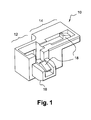
- a mounting bracket 10 comprises a block moulded from a plastics material. At one side, the bracket 10 has an aperture 12 having a rectangular cross section for accepting a correspondingly shaped portion of a heat exchanger. An attachment member 16 projects from the body member of the bracket 10 and has a chamfered end in order to assist insertion into a recess in a bracket of the heat exchanger. At the opposite side the bracket 10 has a lip 14 for connection to a portion of the heat exchanger. Both the lip 14 and the attachment member 16 have resilient means in the form of biased detents 18.
- the mounting bracket 10 is used to mount a first heat exchanging component 20 onto a second heat exchanging component 22 of an automobile.
- the rectangular aperture 12 of the bracket 10 is placed over a corresponding formation on the second heat exchanger 22.
- the detent 18 on the lip 14 snaps into engagement with a connection bracket 24 of the second heat exchanging component 22. This secures the mounting bracket 10 to the second heat exchanging component 22.
- a connecting bracket 26 of the first exchanging component is brought towards the projecting attachment portion 16 until the chamfered portions of the attachment member 16 meets the bracket 26.
- mounting bracket Although only a single mounting bracket is shown in the figures, it will be appreciated that use of more than one mounting bracket may be desirable, for example it may be desirable to have mounting bracket at each of the four corners of the heat exchanging components. Alternatively, mounting hooks H may be used at selected corners, such as at the corners toward the bottom of the heat exchanger component, as shown in Fig. 3 .
- the mounting bracket provides both a hanging function and a locating function for the heat exchanger component. This maximises the size of heat exchangers which can be used in a given application.
Landscapes
- Engineering & Computer Science (AREA)
- Physics & Mathematics (AREA)
- Thermal Sciences (AREA)
- Mechanical Engineering (AREA)
- General Engineering & Computer Science (AREA)
- Details Of Heat-Exchange And Heat-Transfer (AREA)
- Air-Conditioning For Vehicles (AREA)
- Mechanical Control Devices (AREA)
- Connection Of Plates (AREA)
Abstract
- a body member having a formation which is engageable with a corresponding formation on the second component (22) to which the first component (20) is to be attached to;
- at least an attachment member (16) protruding from the body member, wherein the attachment member (16) is provided with resilient means (18) co-operable with a corresponding formation on the first component (20).
Description
- The present invention relates to a mounting bracket, particularly, but not exclusively, a mounting bracket for mounting a first heat exchanging component to a second heat exchanging component in an automobile.
- It is necessary to ensure that heat exchanging components are mounted securely in their operative positions. This is a particular issue in automobile heat exchangers. The means for mounting the components must be such that it is resilient enough to withstand certain vibrations and impact forces, yet remains a relatively straightforward form of attachment.
- According to the present invention, there is provided a mounting bracket for mounting a first component onto a second component, the mounting bracket comprising:
- a body member having a formation which is engageable with a corresponding formation on the second component to which the first component is to be attached to;
at least an attachment member protruding from the body member, wherein the attachment member is provided with resilient means co-operable with a corresponding formation on the first component. - Preferably, the body member is also provided with resilient means co-operable with a corresponding formation on the second component.
- Preferably, the body member comprises a plastics block having a substantially rectangular aperture for receiving a corresponding rectangular protrusion on the second component.
- Preferably, the attachment member comprises a rectangular protrusion having the resilient means mounted thereon. More preferably, the resilient means comprises a biased detent adapted to deform from an outward position to an inward position as it engages with the component and return back to its original position when the first and second components are mounted to one another.
- Preferably, the first and second components are heat exchanger components for an automobile.
- Embodiments of the present invention will now be described, with reference to the accompanying drawings, in which:-
-
Fig 1 is a perspective view of the mounting bracket according to the present invention; -
Fig. 2 is a perspective view of the mounting bracket ofFig. 1 in use when mounting a first heat exchanger component to a second heat exchanger component; and -
Fig. 3 is a perspective view of a mounting hook, not in accordance with the present invention, located toward the bottom of the heat exchanger component. - With reference to
Fig. 1 , amounting bracket 10 comprises a block moulded from a plastics material. At one side, thebracket 10 has anaperture 12 having a rectangular cross section for accepting a correspondingly shaped portion of a heat exchanger. Anattachment member 16 projects from the body member of thebracket 10 and has a chamfered end in order to assist insertion into a recess in a bracket of the heat exchanger. At the opposite side thebracket 10 has alip 14 for connection to a portion of the heat exchanger. Both thelip 14 and theattachment member 16 have resilient means in the form ofbiased detents 18. - In the embodiment shown, the
mounting bracket 10 is used to mount a firstheat exchanging component 20 onto a secondheat exchanging component 22 of an automobile. Therectangular aperture 12 of thebracket 10 is placed over a corresponding formation on thesecond heat exchanger 22. At the same time, the detent 18 on thelip 14 snaps into engagement with aconnection bracket 24 of the secondheat exchanging component 22. This secures themounting bracket 10 to the secondheat exchanging component 22. In order to mount the first heat exchanging component onto the second heat exchanging component a connecting bracket 26 of the first exchanging component is brought towards the projectingattachment portion 16 until the chamfered portions of theattachment member 16 meets the bracket 26. At this point further movement of the first heat exchanging component towards the second heat exchanging component will cause thebiased detent 18 to move inwardly and allow the attachment portion to pass into the bracket 26 of the firstheat exchanging component 20. Once the attachment portion has been fully inserted into the bracket 26, the biased detent snaps outwardly to lock the first heat exchanging component to the second heat exchanging component. - Although only a single mounting bracket is shown in the figures, it will be appreciated that use of more than one mounting bracket may be desirable, for example it may be desirable to have mounting bracket at each of the four corners of the heat exchanging components. Alternatively, mounting hooks H may be used at selected corners, such as at the corners toward the bottom of the heat exchanger component, as shown in
Fig. 3 . - The mounting bracket provides both a hanging function and a locating function for the heat exchanger component. This maximises the size of heat exchangers which can be used in a given application.
- Other advantages of the mounting bracket of the present invention include:
- providing a secure and reliable bracket which requires a minimal amount of space;
minimising the number of components required by minimising the need for screws and other fasting means; and
allowing the components to be attached to one another very quickly and easily. - Modifications and improvements may be made to the foregoing without departing from the scope of the present invention, for example:-
- Although, in the above description, the mounting bracket is used to mount a first heat exchanging component to a second heat exchanging component, it is clearly not limited to first and second components; it could be used to mount additional (third, fourth etc.) heat exchanging components to one another.
Claims (6)
- A mounting bracket (10) for mounting a first component (20) onto a second component (22), the mounting bracket (10) comprising:- a body member having a formation which is engageable with a corresponding formation on the second component (22) to which the first component (20) is to be attached to;- at least an attachment member (16) protruding from the body member, wherein the attachment member (16) is provided with resilient means co-operable with a corresponding formation on the first component (20).
- The mounting bracket (10) according to claim 1, characterized in that the body member is also provided with resilient means co-operable with a corresponding formation on the second component (22).
- The mounting bracket (10) according to claim 1 or 2, characterized in that the body member comprises a plastics block having a substantially rectangular aperture for receiving a corresponding rectangular protrusion on the second component (22).
- The mounting bracket (10) according to anyone of claims 1 to 3, characterized in that the attachment member comprises a rectangular protrusion having the resilient means mounted thereon.
- The mounting bracket (10) according to anyone of claims 1 to 4, characterized in that the resilient means comprises a biased detent adapted to deform from an outward position to an inward position as it engages with the component and return back to its original position when the first and second components (20, 22) are mounted to one another.
- The mounting bracket (10) according to anyone of claims 1 to 5, characterized in that the first and second components (20, 22) are heat exchanger components for an automobile.
Priority Applications (1)
| Application Number | Priority Date | Filing Date | Title |
|---|---|---|---|
| US11/999,156 US20080156456A1 (en) | 2006-12-27 | 2007-12-04 | Mounting bracket |
Applications Claiming Priority (1)
| Application Number | Priority Date | Filing Date | Title |
|---|---|---|---|
| GBGB0625680.4A GB0625680D0 (en) | 2006-12-27 | 2006-12-27 | Mounting bracket |
Publications (3)
| Publication Number | Publication Date |
|---|---|
| EP1939575A2 true EP1939575A2 (en) | 2008-07-02 |
| EP1939575A3 EP1939575A3 (en) | 2013-05-22 |
| EP1939575B1 EP1939575B1 (en) | 2018-07-25 |
Family
ID=37734728
Family Applications (1)
| Application Number | Title | Priority Date | Filing Date |
|---|---|---|---|
| EP07121646.9A Not-in-force EP1939575B1 (en) | 2006-12-27 | 2007-11-27 | Arrangement of a first component mounted onto a second component by means of a mounting bracket |
Country Status (3)
| Country | Link |
|---|---|
| US (1) | US20080156456A1 (en) |
| EP (1) | EP1939575B1 (en) |
| GB (1) | GB0625680D0 (en) |
Cited By (3)
| Publication number | Priority date | Publication date | Assignee | Title |
|---|---|---|---|---|
| EP2418451A3 (en) * | 2010-08-13 | 2014-04-16 | Behr GmbH & Co. KG | Arrangement for connecting a heat exchanger with another component |
| DE102013215393A1 (en) * | 2013-08-05 | 2015-02-05 | Behr Gmbh & Co. Kg | Arrangement for fastening a heat exchanger module |
| EP2146169B1 (en) * | 2008-07-15 | 2018-02-21 | MAHLE Behr GmbH & Co. KG | Device for attaching a coolant condenser to a coolant cooler |
Families Citing this family (4)
| Publication number | Priority date | Publication date | Assignee | Title |
|---|---|---|---|---|
| ITTO20100667A1 (en) * | 2010-08-02 | 2012-02-03 | Gate Srl | COOLING GROUP FOR A MOTOR VEHICLE |
| JP5660024B2 (en) * | 2011-12-27 | 2015-01-28 | 株式会社デンソー | Heat exchanger assembly structure |
| US9146061B2 (en) * | 2013-05-06 | 2015-09-29 | Denso International America, Inc. | Fastener-less retained heat exchanger mounting bracket for low installation force |
| DE102017221504A1 (en) * | 2017-11-30 | 2019-06-06 | Robert Bosch Gmbh | Component for connecting a hydraulic unit of a heating device |
Citations (1)
| Publication number | Priority date | Publication date | Assignee | Title |
|---|---|---|---|---|
| DE102004043354A1 (en) | 2004-09-08 | 2006-03-09 | Hbpo Gmbh | Device for fastening a heat exchanger, in particular a coolant radiator for motor vehicles |
Family Cites Families (7)
| Publication number | Priority date | Publication date | Assignee | Title |
|---|---|---|---|---|
| US5489078A (en) * | 1994-10-03 | 1996-02-06 | Risley; Nathaniel H. | Container clip |
| EP0783992A1 (en) * | 1996-01-10 | 1997-07-16 | Koninklijke Philips Electronics N.V. | Cradle for a portable radio terminal |
| FR2838792B1 (en) * | 2002-04-18 | 2004-10-29 | Plastic Omnium Cie | DEVICE FOR FIXING A FUNCTIONAL MEMBER ON A MOTOR VEHICLE STRUCTURAL PART AND STRUCTURAL PART PARTIALLY INTEGRATING SUCH A DEVICE |
| PL359542A1 (en) * | 2003-04-04 | 2004-10-18 | Delphi Technologies, Inc. | Self-latching bracket |
| US7131170B2 (en) * | 2003-06-27 | 2006-11-07 | Quickie Manufacturing Corporation | Threaded push broom locking clip |
| US7117927B2 (en) * | 2004-09-14 | 2006-10-10 | Delphi Technologies, Inc. | Snap-on mounting bracket for heat exchangers |
| US7429023B2 (en) * | 2006-09-29 | 2008-09-30 | Morrow Michael L | Deck support |
-
2006
- 2006-12-27 GB GBGB0625680.4A patent/GB0625680D0/en not_active Ceased
-
2007
- 2007-11-27 EP EP07121646.9A patent/EP1939575B1/en not_active Not-in-force
- 2007-12-04 US US11/999,156 patent/US20080156456A1/en not_active Abandoned
Patent Citations (1)
| Publication number | Priority date | Publication date | Assignee | Title |
|---|---|---|---|---|
| DE102004043354A1 (en) | 2004-09-08 | 2006-03-09 | Hbpo Gmbh | Device for fastening a heat exchanger, in particular a coolant radiator for motor vehicles |
Cited By (3)
| Publication number | Priority date | Publication date | Assignee | Title |
|---|---|---|---|---|
| EP2146169B1 (en) * | 2008-07-15 | 2018-02-21 | MAHLE Behr GmbH & Co. KG | Device for attaching a coolant condenser to a coolant cooler |
| EP2418451A3 (en) * | 2010-08-13 | 2014-04-16 | Behr GmbH & Co. KG | Arrangement for connecting a heat exchanger with another component |
| DE102013215393A1 (en) * | 2013-08-05 | 2015-02-05 | Behr Gmbh & Co. Kg | Arrangement for fastening a heat exchanger module |
Also Published As
| Publication number | Publication date |
|---|---|
| GB0625680D0 (en) | 2007-01-31 |
| EP1939575B1 (en) | 2018-07-25 |
| EP1939575A3 (en) | 2013-05-22 |
| US20080156456A1 (en) | 2008-07-03 |
Similar Documents
| Publication | Publication Date | Title |
|---|---|---|
| EP1939575B1 (en) | Arrangement of a first component mounted onto a second component by means of a mounting bracket | |
| JP2005029159A (en) | Radiator attaching assembly, device component, and method | |
| JP2005220795A (en) | Reserving tank mounting structure for motor fan shroud | |
| US20060053598A1 (en) | Holder for a heat exchanger | |
| US9306327B1 (en) | Clip for wire harness | |
| CN102640371A (en) | Mounting and latching mechanism for standard rails | |
| US20080302557A1 (en) | Attachment Device for an Electrical Connection Terminal for Attachment to a Housing Wall | |
| JP4875748B2 (en) | Connecting sleeve for connecting two pipes each with one connecting collar | |
| JP2009525220A (en) | Device for slidable holding of a glass plate in a guide rail | |
| EP1686341A1 (en) | Cooling assembly for vehicles | |
| EP4060837A1 (en) | Mounting kit adapted for a rail component and related rail mounting system | |
| CN113964568B (en) | Current holding clamp | |
| JP2005096597A (en) | Part mounting clip | |
| JP3218364B2 (en) | Furniture component mounting bracket | |
| JP3068533U (en) | Fixing structure for resin parts | |
| JP6916160B2 (en) | adapter | |
| JP5154302B2 (en) | Air cooler | |
| JP2000041810A (en) | Mirror fixture | |
| JP4891279B2 (en) | Two-part assembly structure | |
| CN119022204B (en) | System for mounting on a surface | |
| EP1887305A1 (en) | Fastening device for a heat exchanger core, particularly for a motor vehicle | |
| US7046510B2 (en) | Technique for mounting a power supply in a computer | |
| SE518976C2 (en) | Method for mounting and locking a cover lid via a hook means releasably and concealed by a convector element fitted with a plurality of flange elements and a method for mounting the cover lid and convector element at a wall portion. | |
| US20190162423A1 (en) | Component for connecting a hydraulic unit of a heating device | |
| WO2025140772A1 (en) | Carrier for a storage device and computer system |
Legal Events
| Date | Code | Title | Description |
|---|---|---|---|
| PUAI | Public reference made under article 153(3) epc to a published international application that has entered the european phase |
Free format text: ORIGINAL CODE: 0009012 |
|
| AK | Designated contracting states |
Kind code of ref document: A2 Designated state(s): AT BE BG CH CY CZ DE DK EE ES FI FR GB GR HU IE IS IT LI LT LU LV MC MT NL PL PT RO SE SI SK TR |
|
| AX | Request for extension of the european patent |
Extension state: AL BA HR MK RS |
|
| PUAL | Search report despatched |
Free format text: ORIGINAL CODE: 0009013 |
|
| AK | Designated contracting states |
Kind code of ref document: A3 Designated state(s): AT BE BG CH CY CZ DE DK EE ES FI FR GB GR HU IE IS IT LI LT LU LV MC MT NL PL PT RO SE SI SK TR |
|
| AX | Request for extension of the european patent |
Extension state: AL BA HR MK RS |
|
| RIC1 | Information provided on ipc code assigned before grant |
Ipc: F28D 1/04 20060101ALI20130416BHEP Ipc: F28F 9/00 20060101AFI20130416BHEP |
|
| 17P | Request for examination filed |
Effective date: 20131122 |
|
| RBV | Designated contracting states (corrected) |
Designated state(s): AT BE BG CH CY CZ DE DK EE ES FI FR GB GR HU IE IS IT LI LT LU LV MC MT NL PL PT RO SE SI SK TR |
|
| AKX | Designation fees paid |
Designated state(s): AT BE BG CH CY CZ DE DK EE ES FI FR GB GR HU IE IS IT LI LT LU LV MC MT NL PL PT RO SE SI SK TR |
|
| 17Q | First examination report despatched |
Effective date: 20140722 |
|
| RAP1 | Party data changed (applicant data changed or rights of an application transferred) |
Owner name: MAHLE INTERNATIONAL GMBH |
|
| GRAP | Despatch of communication of intention to grant a patent |
Free format text: ORIGINAL CODE: EPIDOSNIGR1 |
|
| INTG | Intention to grant announced |
Effective date: 20180323 |
|
| GRAS | Grant fee paid |
Free format text: ORIGINAL CODE: EPIDOSNIGR3 |
|
| GRAA | (expected) grant |
Free format text: ORIGINAL CODE: 0009210 |
|
| AK | Designated contracting states |
Kind code of ref document: B1 Designated state(s): AT BE BG CH CY CZ DE DK EE ES FI FR GB GR HU IE IS IT LI LT LU LV MC MT NL PL PT RO SE SI SK TR |
|
| REG | Reference to a national code |
Ref country code: GB Ref legal event code: FG4D |
|
| REG | Reference to a national code |
Ref country code: CH Ref legal event code: EP |
|
| REG | Reference to a national code |
Ref country code: AT Ref legal event code: REF Ref document number: 1022221 Country of ref document: AT Kind code of ref document: T Effective date: 20180815 |
|
| REG | Reference to a national code |
Ref country code: IE Ref legal event code: FG4D |
|
| REG | Reference to a national code |
Ref country code: DE Ref legal event code: R096 Ref document number: 602007055491 Country of ref document: DE |
|
| REG | Reference to a national code |
Ref country code: NL Ref legal event code: MP Effective date: 20180725 |
|
| REG | Reference to a national code |
Ref country code: LT Ref legal event code: MG4D |
|
| PG25 | Lapsed in a contracting state [announced via postgrant information from national office to epo] |
Ref country code: NL Free format text: LAPSE BECAUSE OF FAILURE TO SUBMIT A TRANSLATION OF THE DESCRIPTION OR TO PAY THE FEE WITHIN THE PRESCRIBED TIME-LIMIT Effective date: 20180725 |
|
| REG | Reference to a national code |
Ref country code: AT Ref legal event code: MK05 Ref document number: 1022221 Country of ref document: AT Kind code of ref document: T Effective date: 20180725 |
|
| PG25 | Lapsed in a contracting state [announced via postgrant information from national office to epo] |
Ref country code: GR Free format text: LAPSE BECAUSE OF FAILURE TO SUBMIT A TRANSLATION OF THE DESCRIPTION OR TO PAY THE FEE WITHIN THE PRESCRIBED TIME-LIMIT Effective date: 20181026 Ref country code: AT Free format text: LAPSE BECAUSE OF FAILURE TO SUBMIT A TRANSLATION OF THE DESCRIPTION OR TO PAY THE FEE WITHIN THE PRESCRIBED TIME-LIMIT Effective date: 20180725 Ref country code: LT Free format text: LAPSE BECAUSE OF FAILURE TO SUBMIT A TRANSLATION OF THE DESCRIPTION OR TO PAY THE FEE WITHIN THE PRESCRIBED TIME-LIMIT Effective date: 20180725 Ref country code: IS Free format text: LAPSE BECAUSE OF FAILURE TO SUBMIT A TRANSLATION OF THE DESCRIPTION OR TO PAY THE FEE WITHIN THE PRESCRIBED TIME-LIMIT Effective date: 20181125 Ref country code: BG Free format text: LAPSE BECAUSE OF FAILURE TO SUBMIT A TRANSLATION OF THE DESCRIPTION OR TO PAY THE FEE WITHIN THE PRESCRIBED TIME-LIMIT Effective date: 20181025 Ref country code: FI Free format text: LAPSE BECAUSE OF FAILURE TO SUBMIT A TRANSLATION OF THE DESCRIPTION OR TO PAY THE FEE WITHIN THE PRESCRIBED TIME-LIMIT Effective date: 20180725 Ref country code: PL Free format text: LAPSE BECAUSE OF FAILURE TO SUBMIT A TRANSLATION OF THE DESCRIPTION OR TO PAY THE FEE WITHIN THE PRESCRIBED TIME-LIMIT Effective date: 20180725 Ref country code: SE Free format text: LAPSE BECAUSE OF FAILURE TO SUBMIT A TRANSLATION OF THE DESCRIPTION OR TO PAY THE FEE WITHIN THE PRESCRIBED TIME-LIMIT Effective date: 20180725 |
|
| PG25 | Lapsed in a contracting state [announced via postgrant information from national office to epo] |
Ref country code: ES Free format text: LAPSE BECAUSE OF FAILURE TO SUBMIT A TRANSLATION OF THE DESCRIPTION OR TO PAY THE FEE WITHIN THE PRESCRIBED TIME-LIMIT Effective date: 20180725 Ref country code: LV Free format text: LAPSE BECAUSE OF FAILURE TO SUBMIT A TRANSLATION OF THE DESCRIPTION OR TO PAY THE FEE WITHIN THE PRESCRIBED TIME-LIMIT Effective date: 20180725 |
|
| REG | Reference to a national code |
Ref country code: DE Ref legal event code: R097 Ref document number: 602007055491 Country of ref document: DE |
|
| PG25 | Lapsed in a contracting state [announced via postgrant information from national office to epo] |
Ref country code: EE Free format text: LAPSE BECAUSE OF FAILURE TO SUBMIT A TRANSLATION OF THE DESCRIPTION OR TO PAY THE FEE WITHIN THE PRESCRIBED TIME-LIMIT Effective date: 20180725 Ref country code: IT Free format text: LAPSE BECAUSE OF FAILURE TO SUBMIT A TRANSLATION OF THE DESCRIPTION OR TO PAY THE FEE WITHIN THE PRESCRIBED TIME-LIMIT Effective date: 20180725 Ref country code: RO Free format text: LAPSE BECAUSE OF FAILURE TO SUBMIT A TRANSLATION OF THE DESCRIPTION OR TO PAY THE FEE WITHIN THE PRESCRIBED TIME-LIMIT Effective date: 20180725 Ref country code: CZ Free format text: LAPSE BECAUSE OF FAILURE TO SUBMIT A TRANSLATION OF THE DESCRIPTION OR TO PAY THE FEE WITHIN THE PRESCRIBED TIME-LIMIT Effective date: 20180725 |
|
| PGFP | Annual fee paid to national office [announced via postgrant information from national office to epo] |
Ref country code: DE Payment date: 20190131 Year of fee payment: 12 |
|
| PG25 | Lapsed in a contracting state [announced via postgrant information from national office to epo] |
Ref country code: DK Free format text: LAPSE BECAUSE OF FAILURE TO SUBMIT A TRANSLATION OF THE DESCRIPTION OR TO PAY THE FEE WITHIN THE PRESCRIBED TIME-LIMIT Effective date: 20180725 Ref country code: SK Free format text: LAPSE BECAUSE OF FAILURE TO SUBMIT A TRANSLATION OF THE DESCRIPTION OR TO PAY THE FEE WITHIN THE PRESCRIBED TIME-LIMIT Effective date: 20180725 |
|
| PLBE | No opposition filed within time limit |
Free format text: ORIGINAL CODE: 0009261 |
|
| STAA | Information on the status of an ep patent application or granted ep patent |
Free format text: STATUS: NO OPPOSITION FILED WITHIN TIME LIMIT |
|
| REG | Reference to a national code |
Ref country code: CH Ref legal event code: PL |
|
| 26N | No opposition filed |
Effective date: 20190426 |
|
| GBPC | Gb: european patent ceased through non-payment of renewal fee |
Effective date: 20181127 |
|
| PG25 | Lapsed in a contracting state [announced via postgrant information from national office to epo] |
Ref country code: LU Free format text: LAPSE BECAUSE OF NON-PAYMENT OF DUE FEES Effective date: 20181127 Ref country code: MC Free format text: LAPSE BECAUSE OF FAILURE TO SUBMIT A TRANSLATION OF THE DESCRIPTION OR TO PAY THE FEE WITHIN THE PRESCRIBED TIME-LIMIT Effective date: 20180725 |
|
| REG | Reference to a national code |
Ref country code: BE Ref legal event code: MM Effective date: 20181130 |
|
| REG | Reference to a national code |
Ref country code: IE Ref legal event code: MM4A |
|
| PG25 | Lapsed in a contracting state [announced via postgrant information from national office to epo] |
Ref country code: LI Free format text: LAPSE BECAUSE OF NON-PAYMENT OF DUE FEES Effective date: 20181130 Ref country code: CH Free format text: LAPSE BECAUSE OF NON-PAYMENT OF DUE FEES Effective date: 20181130 Ref country code: SI Free format text: LAPSE BECAUSE OF FAILURE TO SUBMIT A TRANSLATION OF THE DESCRIPTION OR TO PAY THE FEE WITHIN THE PRESCRIBED TIME-LIMIT Effective date: 20180725 |
|
| PG25 | Lapsed in a contracting state [announced via postgrant information from national office to epo] |
Ref country code: IE Free format text: LAPSE BECAUSE OF NON-PAYMENT OF DUE FEES Effective date: 20181127 Ref country code: FR Free format text: LAPSE BECAUSE OF NON-PAYMENT OF DUE FEES Effective date: 20181130 |
|
| PG25 | Lapsed in a contracting state [announced via postgrant information from national office to epo] |
Ref country code: BE Free format text: LAPSE BECAUSE OF NON-PAYMENT OF DUE FEES Effective date: 20181130 |
|
| PG25 | Lapsed in a contracting state [announced via postgrant information from national office to epo] |
Ref country code: GB Free format text: LAPSE BECAUSE OF NON-PAYMENT OF DUE FEES Effective date: 20181127 |
|
| PG25 | Lapsed in a contracting state [announced via postgrant information from national office to epo] |
Ref country code: MT Free format text: LAPSE BECAUSE OF NON-PAYMENT OF DUE FEES Effective date: 20181127 |
|
| PG25 | Lapsed in a contracting state [announced via postgrant information from national office to epo] |
Ref country code: TR Free format text: LAPSE BECAUSE OF FAILURE TO SUBMIT A TRANSLATION OF THE DESCRIPTION OR TO PAY THE FEE WITHIN THE PRESCRIBED TIME-LIMIT Effective date: 20180725 |
|
| PG25 | Lapsed in a contracting state [announced via postgrant information from national office to epo] |
Ref country code: PT Free format text: LAPSE BECAUSE OF FAILURE TO SUBMIT A TRANSLATION OF THE DESCRIPTION OR TO PAY THE FEE WITHIN THE PRESCRIBED TIME-LIMIT Effective date: 20180725 |
|
| REG | Reference to a national code |
Ref country code: DE Ref legal event code: R119 Ref document number: 602007055491 Country of ref document: DE |
|
| PG25 | Lapsed in a contracting state [announced via postgrant information from national office to epo] |
Ref country code: CY Free format text: LAPSE BECAUSE OF FAILURE TO SUBMIT A TRANSLATION OF THE DESCRIPTION OR TO PAY THE FEE WITHIN THE PRESCRIBED TIME-LIMIT Effective date: 20180725 Ref country code: HU Free format text: LAPSE BECAUSE OF FAILURE TO SUBMIT A TRANSLATION OF THE DESCRIPTION OR TO PAY THE FEE WITHIN THE PRESCRIBED TIME-LIMIT; INVALID AB INITIO Effective date: 20071127 |
|
| PG25 | Lapsed in a contracting state [announced via postgrant information from national office to epo] |
Ref country code: DE Free format text: LAPSE BECAUSE OF NON-PAYMENT OF DUE FEES Effective date: 20200603 |