EP1939573A1 - Evaporator - Google Patents
Evaporator Download PDFInfo
- Publication number
- EP1939573A1 EP1939573A1 EP06811874A EP06811874A EP1939573A1 EP 1939573 A1 EP1939573 A1 EP 1939573A1 EP 06811874 A EP06811874 A EP 06811874A EP 06811874 A EP06811874 A EP 06811874A EP 1939573 A1 EP1939573 A1 EP 1939573A1
- Authority
- EP
- European Patent Office
- Prior art keywords
- refrigerant
- tubes
- tank
- evaporator
- path
- Prior art date
- Legal status (The legal status is an assumption and is not a legal conclusion. Google has not performed a legal analysis and makes no representation as to the accuracy of the status listed.)
- Withdrawn
Links
- 239000003507 refrigerant Substances 0.000 claims abstract description 128
- 239000007791 liquid phase Substances 0.000 description 11
- 210000000078 claw Anatomy 0.000 description 7
- 239000011324 bead Substances 0.000 description 5
- 238000001816 cooling Methods 0.000 description 5
- 239000012071 phase Substances 0.000 description 5
- 230000000694 effects Effects 0.000 description 2
- 230000007423 decrease Effects 0.000 description 1
- 230000003247 decreasing effect Effects 0.000 description 1
- 238000005192 partition Methods 0.000 description 1
- 230000003014 reinforcing effect Effects 0.000 description 1
- 238000000926 separation method Methods 0.000 description 1
Images


Classifications
-
- F—MECHANICAL ENGINEERING; LIGHTING; HEATING; WEAPONS; BLASTING
- F28—HEAT EXCHANGE IN GENERAL
- F28D—HEAT-EXCHANGE APPARATUS, NOT PROVIDED FOR IN ANOTHER SUBCLASS, IN WHICH THE HEAT-EXCHANGE MEDIA DO NOT COME INTO DIRECT CONTACT
- F28D1/00—Heat-exchange apparatus having stationary conduit assemblies for one heat-exchange medium only, the media being in contact with different sides of the conduit wall, in which the other heat-exchange medium is a large body of fluid, e.g. domestic or motor car radiators
- F28D1/02—Heat-exchange apparatus having stationary conduit assemblies for one heat-exchange medium only, the media being in contact with different sides of the conduit wall, in which the other heat-exchange medium is a large body of fluid, e.g. domestic or motor car radiators with heat-exchange conduits immersed in the body of fluid
- F28D1/03—Heat-exchange apparatus having stationary conduit assemblies for one heat-exchange medium only, the media being in contact with different sides of the conduit wall, in which the other heat-exchange medium is a large body of fluid, e.g. domestic or motor car radiators with heat-exchange conduits immersed in the body of fluid with plate-like or laminated conduits
- F28D1/0308—Heat-exchange apparatus having stationary conduit assemblies for one heat-exchange medium only, the media being in contact with different sides of the conduit wall, in which the other heat-exchange medium is a large body of fluid, e.g. domestic or motor car radiators with heat-exchange conduits immersed in the body of fluid with plate-like or laminated conduits the conduits being formed by paired plates touching each other
- F28D1/0325—Heat-exchange apparatus having stationary conduit assemblies for one heat-exchange medium only, the media being in contact with different sides of the conduit wall, in which the other heat-exchange medium is a large body of fluid, e.g. domestic or motor car radiators with heat-exchange conduits immersed in the body of fluid with plate-like or laminated conduits the conduits being formed by paired plates touching each other the plates having lateral openings therein for circulation of the heat-exchange medium from one conduit to another
- F28D1/0333—Heat-exchange apparatus having stationary conduit assemblies for one heat-exchange medium only, the media being in contact with different sides of the conduit wall, in which the other heat-exchange medium is a large body of fluid, e.g. domestic or motor car radiators with heat-exchange conduits immersed in the body of fluid with plate-like or laminated conduits the conduits being formed by paired plates touching each other the plates having lateral openings therein for circulation of the heat-exchange medium from one conduit to another the plates having integrated connecting members
- F28D1/0341—Heat-exchange apparatus having stationary conduit assemblies for one heat-exchange medium only, the media being in contact with different sides of the conduit wall, in which the other heat-exchange medium is a large body of fluid, e.g. domestic or motor car radiators with heat-exchange conduits immersed in the body of fluid with plate-like or laminated conduits the conduits being formed by paired plates touching each other the plates having lateral openings therein for circulation of the heat-exchange medium from one conduit to another the plates having integrated connecting members with U-flow or serpentine-flow inside the conduits
-
- F—MECHANICAL ENGINEERING; LIGHTING; HEATING; WEAPONS; BLASTING
- F25—REFRIGERATION OR COOLING; COMBINED HEATING AND REFRIGERATION SYSTEMS; HEAT PUMP SYSTEMS; MANUFACTURE OR STORAGE OF ICE; LIQUEFACTION SOLIDIFICATION OF GASES
- F25B—REFRIGERATION MACHINES, PLANTS OR SYSTEMS; COMBINED HEATING AND REFRIGERATION SYSTEMS; HEAT PUMP SYSTEMS
- F25B39/00—Evaporators; Condensers
- F25B39/02—Evaporators
- F25B39/022—Evaporators with plate-like or laminated elements
-
- F—MECHANICAL ENGINEERING; LIGHTING; HEATING; WEAPONS; BLASTING
- F25—REFRIGERATION OR COOLING; COMBINED HEATING AND REFRIGERATION SYSTEMS; HEAT PUMP SYSTEMS; MANUFACTURE OR STORAGE OF ICE; LIQUEFACTION SOLIDIFICATION OF GASES
- F25B—REFRIGERATION MACHINES, PLANTS OR SYSTEMS; COMBINED HEATING AND REFRIGERATION SYSTEMS; HEAT PUMP SYSTEMS
- F25B41/00—Fluid-circulation arrangements
-
- F—MECHANICAL ENGINEERING; LIGHTING; HEATING; WEAPONS; BLASTING
- F28—HEAT EXCHANGE IN GENERAL
- F28F—DETAILS OF HEAT-EXCHANGE AND HEAT-TRANSFER APPARATUS, OF GENERAL APPLICATION
- F28F3/00—Plate-like or laminated elements; Assemblies of plate-like or laminated elements
- F28F3/02—Elements or assemblies thereof with means for increasing heat-transfer area, e.g. with fins, with recesses, with corrugations
- F28F3/025—Elements or assemblies thereof with means for increasing heat-transfer area, e.g. with fins, with recesses, with corrugations the means being corrugated, plate-like elements
-
- F—MECHANICAL ENGINEERING; LIGHTING; HEATING; WEAPONS; BLASTING
- F28—HEAT EXCHANGE IN GENERAL
- F28F—DETAILS OF HEAT-EXCHANGE AND HEAT-TRANSFER APPARATUS, OF GENERAL APPLICATION
- F28F9/00—Casings; Header boxes; Auxiliary supports for elements; Auxiliary members within casings
- F28F9/02—Header boxes; End plates
- F28F9/026—Header boxes; End plates with static flow control means, e.g. with means for uniformly distributing heat exchange media into conduits
-
- F—MECHANICAL ENGINEERING; LIGHTING; HEATING; WEAPONS; BLASTING
- F28—HEAT EXCHANGE IN GENERAL
- F28D—HEAT-EXCHANGE APPARATUS, NOT PROVIDED FOR IN ANOTHER SUBCLASS, IN WHICH THE HEAT-EXCHANGE MEDIA DO NOT COME INTO DIRECT CONTACT
- F28D21/00—Heat-exchange apparatus not covered by any of the groups F28D1/00 - F28D20/00
- F28D2021/0019—Other heat exchangers for particular applications; Heat exchange systems not otherwise provided for
- F28D2021/0068—Other heat exchangers for particular applications; Heat exchange systems not otherwise provided for for refrigerant cycles
- F28D2021/0071—Evaporators
Definitions
- the present invention relates to an evaporator.
- a conventional evaporator includes plural tubes which are stacked and have a refrigerant path therein, an upper tank communicating upper ends of the refrigerant paths in the plural tubes one another, and a lower tank communicating lower ends of the refrigerant paths in the plural tubes one another.
- the ratio between the cross-section area of the tanks and cross-section area of the refrigerant paths in the tubes are changed.
- the tank cross-section areas are made smaller, refrigerant in the tanks flows faster and the refrigerant is easily separated into gas-phase refrigerant and liquid phase refrigerant in those tanks. More concretely, it is likely that more liquid phase refrigerant flows in the distal side (opposite side of the refrigerant introducing side) of the tank in a longitudinal direction and accordingly, less liquid phase refrigerant and more gas-phase refrigerant flow in the proximal side (the refrigerant introducing side) of the tank in the longitudinal direction.
- a core section 100A composed of a group of upflow-type tubes 102, which connect the lower tank 112 and an upper tank 110 to flow refrigerant upward from the lower tank 112 to the upper tank 110.
- a square-shaped path section Pa shown in Fig. 19(a) , defined by a tube 2 and an inner fin 9
- a rectangular-shaped path section Pb shown in Fig. 19(b)
- the contact area between the inner wall surface of the path section Pb and refrigerant R increases.
- the square-shaped path section Pa shown in Fig. 19(a) is changed to a triangular shaped path section Pc shown in Fig. 19(c)
- the amount of oil L adhered to the inner wall surface of the path section Pc increases and the contact area decreases.
- the relation can be defined as: the contact area between the path section Pb and refrigerant R > the contact area between the path section Pa and refrigerant R > the contact area between the path section Pc and refrigerant R.
- the relation can be defined as: the flow resistance of the path section Pb ⁇ the flow resistance of the path section Pb ⁇ the flow resistance of the path section Pc.
- the relation can be defined as: the tensile strength of the path section Pa > the tensile strength of the path section Pc > the tensile strength of the path section Pb.
- An evaporator described in Japanese Patent Application Laid-Open No. 2003-75024 includes a distributing resistance plate disposed in an inlet side tank and a resistance plate disposed in an outlet side tank for preventing a non-uniform flow.
- the resistance plate in the inlet side tank can uniform the amounts of refrigerant frown from the tank to the respective tubes.
- this conventional art requires a flow-branching resistance plate and this caused an increased number of parts and accordingly the cost and weight of the evaporator increases.
- the present invention has been made in view of this conventional art and has an object to provide an evaporator capable of reducing the non-uniformity of refrigerant amounts flown from a tank into tubes while preventing a reduction in heat exchange rate.
- An aspect of the present invention is an evaporator having: a plurality of vertical tubes having a refrigerant path therein; an upper tank communicating upper ends of the refrigerant paths in the plural tubes; a lower tank communicating lower ends of the refrigerant paths in the plural tubes; and resistance generators provided in vicinity of inlets of the refrigerant paths and applying resistance to refrigerant flowing from the tank into the refrigerant paths.
- an evaporator 1 of a first embodiment includes tubes 2 and cooling fins 3, which are alternatively stacked.
- a pair of reinforcing side plates 4 is provided at ends, in the stack direction, of the multi-layered body of the tubes 2 and cooling fins 3.
- the tubes 2 are plate-to-plate type tubes, which are formed by combining a pair of flat tube sheets 5, 6 (tube members).
- a first refrigerant path 7 and a second refrigerant path 8, which extend parallel in a longitudinal direction of the tube 2 are formed.
- Inner fins 9 are accommodated in the respective refrigerant paths 7, 8 of the tube 2.
- cylindrical tank forming portions 10a, 11a are formed at one end of the tube 2.
- the tank forming portions 10a, 11a are projected in the stack direction of the tubes 2 and communicate with the ends of the refrigerant paths 7, 8.
- the tank forming portions 10a, 11a are adjacent to each other.
- cylindrical tank forming portions 12a, 13a are formed at the other end of the tube 2.
- the tank forming portions 12a, 13a are projected in the stack direction of the tubes 2 and communicate with the other ends of the refrigerant path 7, 8.
- the tank forming portions 12a, 13a are adjacent to each other.
- the tube sheets 5, 6 constituting the tube 2 are formed with concave portions to communicate with the first refrigerant paths 7 and concave portions to communicate with the second refrigerant paths 8, which extend parallel in a longitudinal direction of the tube sheet 5, 6.
- the cylindrical tank forming portions 10a, 11a which are projected in the stack direction of the tubes 2 and communicate with one ends of the refrigerant paths 7, 8, are formed.
- the cylindrical tank forming portions 12a, 13a which are projected in the stack direction of the tubes 2 and communicate with the other ends of the refrigerant paths 7, 8, are formed.
- refrigerant flows into and out of the first refrigerant path 7 via the tank forming portions 10a, 12a and, similarly, refrigerant flows into and out of the second refrigerant path 8 via the tank forming portions 11a, 13a.
- the inner fin 9 is a thin plate in a waveform shape, as shown in Figs. 8 and 9 .
- the inner fin 9 of the present embodiment has a shape of a thin plate having equally spaced folds at right angle.
- the inner fin 9 thus partitions the refrigerant paths 7, 8 into plural square path sections P when the inner fin 9 is accommodated in the refrigerant paths 7, 8 of the tube 2, as shown in Fig. 7 .
- pairs of tube sheets 5, 6 are combined as accommodating the inner fins 9 therein to form the tubes 2, and then, the tubes 2 and the cooling fins 3 are alternatively stacked. As a result, the evaporator 1 is obtained.
- the tank forming portions 10a, 11a, 12a, 13a of adjacent tubes 2 are connected to each other and tanks 10, 11, 12, 13 are formed.
- the assembled evaporator 1 is positioned to have the refrigerant paths 7, 8 extending in a vertical direction.
- the tanks 10, 11 are disposed in an upper side and the other tanks 12, 13 are disposed in a lower side.
- the refrigerant flows as follows.
- refrigerant is introduced into the upper tank 11 via an inlet pipe (not shown)
- the refrigerant flows in the upper tank 11 toward the right side in Fig. 1 and is distributed to the second refrigerant paths 8 of the respective tubes 2.
- the distributed refrigerant passing through the second refrigerant paths 8 of the tubes 2 moves down to the lower tank 13.
- the refrigerant, which is converged in the lower tank 13 via the second refrigerant paths 8, is introduced into the other lower tank 12 from the lower tank 13 via a communicating pipe (not shown).
- the refrigerant introduced in the lower tank 12 flows in the lower tank 12 toward the left side in Fig.
- the refrigerant passing through the first refrigerant paths 7 of the tubes 2 moves up to the upper tank 10 and is converged in the upper tank 10.
- the refrigerant, which is converged in the upper tank 10 is discharged from the upper tank 10 to the outside the evaporator 1 via an outlet pipe (not shown).
- Heat exchange is performed between the refrigerant flown in the evaporator 1 as described above and air passing through the evaporator.
- air is sent in the direction indicated by the arrow in Fig. 1 , so when air passes through between the tubes 2 and cooling fins 3, heat exchange is firstly performed between the air and refrigerant flowing in the first refrigerant path 7, which is in windward side, and then, heat exchange is performed between the air and refrigerant flowing in the second refrigerant path 8, which is in leeward side.
- resistance generators 21 are provided at inlets of the refrigerant paths 7 to apply resistance to refrigerant flown from the tank 12 into the refrigerant paths 7 of the tubes 2.
- the resistance generators 21 are not provided to the downflow-type refrigerant paths 8 but to the upflow-type refrigerant paths 7.
- the resistance generators 21 are formed as claws 22 provided at ends of the inner fins 9 in a longitudinal direction.
- the claws 22 project into the inlet of the respective path section P and apply resistance to refrigerant flown into the path sections P in order to generate a pressure loss.
- the claws 22 serve as a throttle for decreasing the cross-section area of the path section P at the inlet of the respective path sections P in view of its configuration and as a resistor for applying resistance to refrigerant flow in view of its function.
- the claws 22 apply resistance to refrigerant flow and the refrigerant flow into the respective tubes 2 is restricted, so that the flow amount difference in liquid phase refrigerant among the respective tubes 2 is reduced. Further, the cross-section area of the refrigerant path 7 other than the inlet area is not reduced although the cross-section area of the inlet of the refrigerant path 7 is reduced by the claws 22. Thus, the oil adhesion rate on the refrigerant path 7 is not increased. In other words, it is possible to prevent a reduction of a contact area between the refrigerant and the inner surface of the refrigerant path 7.
- the first embodiment having such a structure, even if the non-uniformity is generated in the distribution of liquid phase refrigerant in the tank 12 due to a separation into liquid phase refrigerant and gas-phase refrigerant in the tank 12, when the refrigerant is flown from the tank 12 into the refrigerant path 7, refrigerant receives resistance by the claws 22 placed at the inlet of the refrigerant path 7 so that non-uniformity of the liquid phase refrigerant flow amounts in the respective refrigerant paths 7 is reduced.
- the temperature distribution is homogenized in the core section composed of the tubes 2 and cooling fins 3 and the temperature variation can be reduced.
- the resistance generator 21 is provided at the inlet of the upflow-type refrigerant path 7 and this is more effective compared to a case that resistance generator is provided at the inlet of the downflow-type refrigerant path 8.
- the claws 22 as the resistance generator 21 are integrally formed with the inner fin 9 so that another member is not required so that an inexpensive, lightweight evaporator is obtained.
- Fig. 12 is a perspective view showing an inner fin of an evaporator according to a second embodiment of the present invention and Fig. 13 is a side view of the inner fin shown in Fig. 12 .
- the same reference numerals and symbols are used to designate the same elements as the elements described in the first embodiment, and redundant description thereof will be omitted.
- the evaporator 1 of the second embodiment has the inner fin 9 having a different configuration from that of the first embodiment but other elements are same as those of the first embodiment. More concretely, the configuration of the resistance generator 21 in the second embodiment differs from that of the first embodiment.
- the inner fin 9 of the second embodiment is composed of a waveform shaped general portion 9a and an offset portion 9b, which is provided at one longitudinal end of the general portion 9a and has waveforms offset to the waveforms of the general portion 9a.
- the waveforms of the offset portion 9b are placed half wavelength off from those of the general portion 9a.
- the offset portion 9b serves as the resistance generator 21 for applying resistance to refrigerant flows by reducing the cross-section area of the inlet of the refrigerant path 7.
- the same operation and effect as the first embodiment can be achieved by providing the offset portion 9b as the resistance generator 21. Further, since the offset portion 9b is integrally formed with the inner fin 9, any separate member is not required.
- Fig. 14 is a side view showing an area around a resistance generator of an evaporator according to a third embodiment of the present invention and Fig. 15 is a sectional view along the line XV-XV in Fig. 14 .
- the same reference numerals and symbols are used to designate the same elements as the elements described in the first embodiment, and redundant description thereof will be omitted.
- the resistance generator 21 is not provided to the inner fin 9 but provided to the tube 2 and this is the difference from the first embodiment.
- the resistance generator 21 of the present embodiment is composed of beads 25, 26, which are provided at a boundary between the refrigerant path 7 and the tank 12 in a manner of projecting inwardly.
- the beads 25, 26 reduce the cross-section area of the inlet of the refrigerant path 7.
- the beads 25, 26 are integrally formed with the tube sheets 5, 6 constituting the tube 2.
- the same operations and effects as the first embodiment can be achieved by proving the beads 25, 26 as the resistance generator 21. Further, since the beads 25, 26 are integrally formed with the tube 2, it is not required to provide a separate member unlike the conventional art, and thus, an inexpensive, lightweight evaporator can be obtained.
- the evaporator having plate-to-plate-type tubes 2 which are formed by combining a pair of tube sheets 5, 6 integrally formed with tank forming portions 10a, 11a, 12a, 13a, have been described as an example.
- the present invention should not be limited to those embodiments and can be applied to evaporators having different configurations, such as an evaporator 200 in which separately provided tubes 202 and tanks 210, 212 are jointed, as shown in Fig. 16 .
- the present invention can be widely applied as evaporators for vehicular air conditioners and evaporators for air conditioners in general machineries or industrial machineries. This is because the present invention uniforms a temperature distribution of an entire core section of an evaporator to reduce its temperature variation, maintains high heat transfer efficiency of the evaporator, and provides an inexpensive and lightweight evaporator.
Landscapes
- Engineering & Computer Science (AREA)
- Physics & Mathematics (AREA)
- Mechanical Engineering (AREA)
- Thermal Sciences (AREA)
- General Engineering & Computer Science (AREA)
- Heat-Exchange Devices With Radiators And Conduit Assemblies (AREA)
- Air-Conditioning For Vehicles (AREA)
Abstract
An evaporator (1) having: a plurality of vertical tubes (2) having a refrigerant path (7, 8) therein; an upper tank (10, 11) communicating upper ends of the refrigerant paths (7, 8) in the plural tubes (2); a lower tank (12, 13) communicating lower ends of the refrigerant paths (7, 8) in the plural tubes (2); and a resistance generators (21) provided in vicinity of inlets of the refrigerant paths (7, 8) and applying resistance to refrigerant flowing from the upper tank (10, 11) or the lower tank (12, 13) into the refrigerant paths (7, 8).
Description
- The present invention relates to an evaporator.
- A conventional evaporator includes plural tubes which are stacked and have a refrigerant path therein, an upper tank communicating upper ends of the refrigerant paths in the plural tubes one another, and a lower tank communicating lower ends of the refrigerant paths in the plural tubes one another.
- When such an evaporator is made thinner, the ratio between the cross-section area of the tanks and cross-section area of the refrigerant paths in the tubes are changed. When the tank cross-section areas are made smaller, refrigerant in the tanks flows faster and the refrigerant is easily separated into gas-phase refrigerant and liquid phase refrigerant in those tanks. More concretely, it is likely that more liquid phase refrigerant flows in the distal side (opposite side of the refrigerant introducing side) of the tank in a longitudinal direction and accordingly, less liquid phase refrigerant and more gas-phase refrigerant flow in the proximal side (the refrigerant introducing side) of the tank in the longitudinal direction.
- In such a case, more gas-phase refrigerant flows in a group of tubes connected to the proximal side of the tank in a longitudinal direction and, on the other hand, more liquid phase refrigerant flows in a group of tubes connected to the distal side of the tank in a longitudinal direction. This causes non-uniformity of the temperature distribution in a core section (a heat exchange section) of the evaporator.
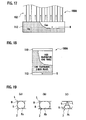
- Particularly, as shown in
Fig. 17 , it is obvious that liquid phase refrigerant and gas phase refrigerant tend to be separated in alower tank 112. As shown inFigs. 17 and 18 , non-uniformity of the temperature distribution is remarkable in acore section 100A composed of a group of upflow-type tubes 102, which connect thelower tank 112 and anupper tank 110 to flow refrigerant upward from thelower tank 112 to theupper tank 110. - It is assumed that such non-uniformity of liquid phase refrigerant can be reduced when the cross-section area of the refrigerant path of the tube is made smaller. However, since oil contained in the refrigerant is adhered to an inner surface of the tube (wall surface of the refrigerant path), the cross-section area of the refrigerant path of the tube is made smaller and contact area between the inner surface of the tube (wall surface of the refrigerant path) and the refrigerant is reduced. This can lower a heat exchange rate of the evaporator.
- For example, when a square-shaped path section Pa, shown in
Fig. 19(a) , defined by atube 2 and aninner fin 9 is changed to a rectangular-shaped path section Pb shown inFig. 19(b) , the contact area between the inner wall surface of the path section Pb and refrigerant R increases. Further, when the square-shaped path section Pa shown inFig. 19(a) is changed to a triangular shaped path section Pc shown inFig. 19(c) , the amount of oil L adhered to the inner wall surface of the path section Pc increases and the contact area decreases. In other words, the relation can be defined as: the contact area between the path section Pb and refrigerant R > the contact area between the path section Pa and refrigerant R > the contact area between the path section Pc and refrigerant R. Also, the relation can be defined as: the flow resistance of the path section Pb < the flow resistance of the path section Pb < the flow resistance of the path section Pc. Further, the relation can be defined as: the tensile strength of the path section Pa > the tensile strength of the path section Pc > the tensile strength of the path section Pb. - An evaporator described in Japanese Patent Application Laid-Open No.
2003-75024 Figs. 2 and3 ) includes a distributing resistance plate disposed in an inlet side tank and a resistance plate disposed in an outlet side tank for preventing a non-uniform flow. - In this evaporator, the resistance plate in the inlet side tank can uniform the amounts of refrigerant frown from the tank to the respective tubes. However, this conventional art requires a flow-branching resistance plate and this caused an increased number of parts and accordingly the cost and weight of the evaporator increases.
- The present invention has been made in view of this conventional art and has an object to provide an evaporator capable of reducing the non-uniformity of refrigerant amounts flown from a tank into tubes while preventing a reduction in heat exchange rate.
- An aspect of the present invention is an evaporator having: a plurality of vertical tubes having a refrigerant path therein; an upper tank communicating upper ends of the refrigerant paths in the plural tubes; a lower tank communicating lower ends of the refrigerant paths in the plural tubes; and resistance generators provided in vicinity of inlets of the refrigerant paths and applying resistance to refrigerant flowing from the tank into the refrigerant paths.
-
-
Fig. 1 is a perspective view of an evaporator according to a first embodiment of the present invention; -
Fig. 2 is an exploded perspective view of the evaporator shown inFig. 1 ; -
Fig. 3 is a plan view of a tube of the evaporator shown inFig. 1 ; -
Fig. 4 is a sectional view along the line IV-IV shown inFig. 3 ; -
Fig. 5 is a sectional view along the line V-V shown inFig. 3 ; -
Fig. 6 is a side view showing an area around a joint of a refrigerant path of the tube and a lower tank; -
Fig. 7 is a sectional view along the line VII-VII shown inFig. 6 ; -
Fig. 8 is a plan view showing an inner fin of the evaporator of the first embodiment; -
Fig. 9 is a sectional view along the line IX-IX shown inFig. 8 ; -
Fig. 10 is a side view of the inner fin shown inFig. 8 ; -
Fig. 11 is a perspective view of the inner fin shown inFig. 8 ; -
Fig. 12 is a perspective view of an inner fin of an evaporator according to a second embodiment of the present invention; -
Fig. 13 is a side view of the inner fin shown inFig. 12 ; -
Fig. 14 is a side view of an area around a resistance generator of an evaporator according to a third embodiment of the present invention; -
Fig. 15 is a sectional view along the line XV-XV shown inFig. 14 ; -
Fig. 16 is a perspective view showing an evaporator composed of a combination of tubes and tanks which are separately provided; -
Fig. 17 is a sectional view showing a refrigerant flow state near a joint of a tank and tubes in a conventional evaporator; -
Fig. 18 is a view showing a temperature distribution state of an entire core section of the conventional evaporator; and -
Figs. 19(a) to 19(c) are sectional views showing path sections of refrigerant paths defined by a tube and an inner fin. - An evaporator of embodiments of the present invention will be described with reference to the drawings.
- As shown in
Figs. 1 and2 , anevaporator 1 of a first embodiment includestubes 2 andcooling fins 3, which are alternatively stacked. A pair of reinforcingside plates 4 is provided at ends, in the stack direction, of the multi-layered body of thetubes 2 and coolingfins 3. - As shown in
Fig. 2 , thetubes 2 are plate-to-plate type tubes, which are formed by combining a pair offlat tube sheets 5, 6 (tube members). In thetube 2, afirst refrigerant path 7 and asecond refrigerant path 8, which extend parallel in a longitudinal direction of thetube 2, are formed.Inner fins 9 are accommodated in therespective refrigerant paths tube 2. - At one end of the
tube 2, cylindricaltank forming portions tank forming portions tubes 2 and communicate with the ends of therefrigerant paths tank forming portions tube 2, cylindricaltank forming portions tank forming portions tubes 2 and communicate with the other ends of therefrigerant path tank forming portions - In other words, the
tube sheets tube 2 are formed with concave portions to communicate with thefirst refrigerant paths 7 and concave portions to communicate with thesecond refrigerant paths 8, which extend parallel in a longitudinal direction of thetube sheet tube sheets tank forming portions tubes 2 and communicate with one ends of therefrigerant paths tube sheets tank forming portions tubes 2 and communicate with the other ends of therefrigerant paths - With such a structure, refrigerant flows into and out of the
first refrigerant path 7 via thetank forming portions second refrigerant path 8 via thetank forming portions - The
inner fin 9 is a thin plate in a waveform shape, as shown inFigs. 8 and 9 . Theinner fin 9 of the present embodiment has a shape of a thin plate having equally spaced folds at right angle. Theinner fin 9 thus partitions therefrigerant paths inner fin 9 is accommodated in therefrigerant paths tube 2, as shown inFig. 7 . - In an assembly of the
evaporator 1, pairs oftube sheets inner fins 9 therein to form thetubes 2, and then, thetubes 2 and thecooling fins 3 are alternatively stacked. As a result, theevaporator 1 is obtained. When the tubes are stacked, thetank forming portions adjacent tubes 2 are connected to each other andtanks evaporator 1 is positioned to have therefrigerant paths Fig. 1 , thetanks other tanks - When refrigerant is introduced in this
evaporator 1, the refrigerant flows as follows. When refrigerant is introduced into theupper tank 11 via an inlet pipe (not shown), the refrigerant flows in theupper tank 11 toward the right side inFig. 1 and is distributed to the secondrefrigerant paths 8 of therespective tubes 2. The distributed refrigerant passing through the secondrefrigerant paths 8 of thetubes 2 moves down to thelower tank 13. The refrigerant, which is converged in thelower tank 13 via the secondrefrigerant paths 8, is introduced into the otherlower tank 12 from thelower tank 13 via a communicating pipe (not shown). The refrigerant introduced in thelower tank 12 flows in thelower tank 12 toward the left side inFig. 1 and is distributed to the firstrefrigerant paths 7 of therespective tubes 2. The refrigerant passing through the firstrefrigerant paths 7 of thetubes 2 moves up to theupper tank 10 and is converged in theupper tank 10. The refrigerant, which is converged in theupper tank 10, is discharged from theupper tank 10 to the outside theevaporator 1 via an outlet pipe (not shown). - Heat exchange is performed between the refrigerant flown in the
evaporator 1 as described above and air passing through the evaporator. According to the present embodiment, air is sent in the direction indicated by the arrow inFig. 1 , so when air passes through between thetubes 2 andcooling fins 3, heat exchange is firstly performed between the air and refrigerant flowing in the firstrefrigerant path 7, which is in windward side, and then, heat exchange is performed between the air and refrigerant flowing in the secondrefrigerant path 8, which is in leeward side. - In the
evaporator 1 of the present embodiment,resistance generators 21 are provided at inlets of therefrigerant paths 7 to apply resistance to refrigerant flown from thetank 12 into therefrigerant paths 7 of thetubes 2. Theresistance generators 21 are not provided to the downflow-type refrigerant paths 8 but to the upflow-type refrigerant paths 7. Theresistance generators 21 are formed asclaws 22 provided at ends of theinner fins 9 in a longitudinal direction. Theclaws 22 project into the inlet of the respective path section P and apply resistance to refrigerant flown into the path sections P in order to generate a pressure loss. In other words, theclaws 22 serve as a throttle for decreasing the cross-section area of the path section P at the inlet of the respective path sections P in view of its configuration and as a resistor for applying resistance to refrigerant flow in view of its function. - According to the first embodiment, when refrigerant moves up from the
tank 12 to therefrigerant paths 7 of thetubes 2, theclaws 22 apply resistance to refrigerant flow and the refrigerant flow into therespective tubes 2 is restricted, so that the flow amount difference in liquid phase refrigerant among therespective tubes 2 is reduced. Further, the cross-section area of therefrigerant path 7 other than the inlet area is not reduced although the cross-section area of the inlet of therefrigerant path 7 is reduced by theclaws 22. Thus, the oil adhesion rate on therefrigerant path 7 is not increased. In other words, it is possible to prevent a reduction of a contact area between the refrigerant and the inner surface of therefrigerant path 7. - According to the first embodiment having such a structure, even if the non-uniformity is generated in the distribution of liquid phase refrigerant in the
tank 12 due to a separation into liquid phase refrigerant and gas-phase refrigerant in thetank 12, when the refrigerant is flown from thetank 12 into therefrigerant path 7, refrigerant receives resistance by theclaws 22 placed at the inlet of therefrigerant path 7 so that non-uniformity of the liquid phase refrigerant flow amounts in the respectiverefrigerant paths 7 is reduced. With this structure, the temperature distribution is homogenized in the core section composed of thetubes 2 andcooling fins 3 and the temperature variation can be reduced. Further, since the wide contact area between the refrigerant and the inner surface of therefrigerant path 7 of eachtube 2 is maintained, an effective heat transfer in theevaporator 1 can be maintained. Further, since the cross-section area of therefrigerant path 7 is not reduced except for the inlet area, an increased flow path resistance in theevaporator 1 can be suppressed. - Generally, uneven distribution of liquid phase refrigerant can often occur in the
lower tank 12 when refrigerant flows from thelower tank 12 to theupper tank 10. In the present embodiment, theresistance generator 21 is provided at the inlet of the upflow-type refrigerant path 7 and this is more effective compared to a case that resistance generator is provided at the inlet of the downflow-type refrigerant path 8. - The
claws 22 as theresistance generator 21 are integrally formed with theinner fin 9 so that another member is not required so that an inexpensive, lightweight evaporator is obtained. -
Fig. 12 is a perspective view showing an inner fin of an evaporator according to a second embodiment of the present invention andFig. 13 is a side view of the inner fin shown inFig. 12 . In the second embodiment, the same reference numerals and symbols are used to designate the same elements as the elements described in the first embodiment, and redundant description thereof will be omitted. - As shown in
Figs. 12 and 13 , theevaporator 1 of the second embodiment has theinner fin 9 having a different configuration from that of the first embodiment but other elements are same as those of the first embodiment. More concretely, the configuration of theresistance generator 21 in the second embodiment differs from that of the first embodiment. Theinner fin 9 of the second embodiment is composed of a waveform shapedgeneral portion 9a and an offsetportion 9b, which is provided at one longitudinal end of thegeneral portion 9a and has waveforms offset to the waveforms of thegeneral portion 9a. The waveforms of the offsetportion 9b are placed half wavelength off from those of thegeneral portion 9a. The offsetportion 9b serves as theresistance generator 21 for applying resistance to refrigerant flows by reducing the cross-section area of the inlet of therefrigerant path 7. - According to the second embodiment, the same operation and effect as the first embodiment can be achieved by providing the offset
portion 9b as theresistance generator 21. Further, since the offsetportion 9b is integrally formed with theinner fin 9, any separate member is not required. -
Fig. 14 is a side view showing an area around a resistance generator of an evaporator according to a third embodiment of the present invention andFig. 15 is a sectional view along the line XV-XV inFig. 14 . In the third embodiment, the same reference numerals and symbols are used to designate the same elements as the elements described in the first embodiment, and redundant description thereof will be omitted. - As shown in
Figs. 14 and 15 , in theevaporator 1 of the third embodiment, theresistance generator 21 is not provided to theinner fin 9 but provided to thetube 2 and this is the difference from the first embodiment. Theresistance generator 21 of the present embodiment is composed ofbeads refrigerant path 7 and thetank 12 in a manner of projecting inwardly. Thebeads refrigerant path 7. Thebeads tube sheets tube 2. - According to the third embodiment, the same operations and effects as the first embodiment can be achieved by proving the
beads resistance generator 21. Further, since thebeads tube 2, it is not required to provide a separate member unlike the conventional art, and thus, an inexpensive, lightweight evaporator can be obtained. - According to the first to third embodiments, the evaporator having plate-to-plate-
type tubes 2, which are formed by combining a pair oftube sheets tank forming portions evaporator 200 in which separately providedtubes 202 andtanks Fig. 16 . - Further, according to the first to third embodiments, structures having a resistance generator at the inlets of the upflow-type refrigerant paths have been described; however, the present invention should not be limited to those embodiments and the resistance generator can be provided at inlets of the downflow-type refrigerant paths, according to need.
- The present invention can be widely applied as evaporators for vehicular air conditioners and evaporators for air conditioners in general machineries or industrial machineries. This is because the present invention uniforms a temperature distribution of an entire core section of an evaporator to reduce its temperature variation, maintains high heat transfer efficiency of the evaporator, and provides an inexpensive and lightweight evaporator.
Claims (5)
- An evaporator comprising:a plurality of vertical tubes having.a refrigerant path therein;an upper tank communicating upper ends of the refrigerant paths in the plural tubes;a lower tank communicating lower ends of the refrigerant paths in the plural tubes; andresistance generators provided in vicinity of inlets of the refrigerant paths and applying resistance to refrigerant flowing from the tank into the refrigerant paths.
- The evaporator according to claim 1, wherein
the plurality of tubes include upflow-type tubes in which refrigerant flows upward from the lower tank to the upper tank, and
the resistance generators are provided in vicinity of the inlets of the refrigerant paths in the upflow-type tubes. - The evaporator according to claim 1, wherein
the tubes are formed with the resistance generators on their inlet side. - The evaporator according to claim 1, further comprising
inner fins provided in the tubes,
wherein the resistance generators are formed on the inner fins at their inlet side. - The evaporator according to claim 1, wherein
each of the tubes is a plate-to-plate type tube formed by combining a pair of plate-like tube members.
Applications Claiming Priority (2)
| Application Number | Priority Date | Filing Date | Title |
|---|---|---|---|
| JP2005302320A JP2007113793A (en) | 2005-10-17 | 2005-10-17 | Evaporator |
| PCT/JP2006/320619 WO2007046358A1 (en) | 2005-10-17 | 2006-10-17 | Evaporator |
Publications (1)
| Publication Number | Publication Date |
|---|---|
| EP1939573A1 true EP1939573A1 (en) | 2008-07-02 |
Family
ID=37962451
Family Applications (1)
| Application Number | Title | Priority Date | Filing Date |
|---|---|---|---|
| EP06811874A Withdrawn EP1939573A1 (en) | 2005-10-17 | 2006-10-17 | Evaporator |
Country Status (4)
| Country | Link |
|---|---|
| US (1) | US20090158772A1 (en) |
| EP (1) | EP1939573A1 (en) |
| JP (1) | JP2007113793A (en) |
| WO (1) | WO2007046358A1 (en) |
Cited By (2)
| Publication number | Priority date | Publication date | Assignee | Title |
|---|---|---|---|---|
| US8166776B2 (en) | 2007-07-27 | 2012-05-01 | Johnson Controls Technology Company | Multichannel heat exchanger |
| EP3182503B1 (en) * | 2014-12-04 | 2021-08-11 | LG Chem, Ltd. | Battery pack |
Families Citing this family (4)
| Publication number | Priority date | Publication date | Assignee | Title |
|---|---|---|---|---|
| JP5221329B2 (en) * | 2008-12-26 | 2013-06-26 | 東京ラヂエーター製造株式会社 | Waveby fin |
| US10767937B2 (en) | 2011-10-19 | 2020-09-08 | Carrier Corporation | Flattened tube finned heat exchanger and fabrication method |
| US20200166293A1 (en) * | 2018-11-27 | 2020-05-28 | Hamilton Sundstrand Corporation | Weaved cross-flow heat exchanger and method of forming a heat exchanger |
| US10890381B2 (en) | 2019-01-15 | 2021-01-12 | Hamilton Sundstrand Corporation | Cross-flow heat exchanger |
Family Cites Families (5)
| Publication number | Priority date | Publication date | Assignee | Title |
|---|---|---|---|---|
| US1316199A (en) * | 1919-09-16 | Philmobb iv spebt | ||
| US1996498A (en) * | 1934-06-18 | 1935-04-02 | Young Radiator Co | Heat transfer device |
| US2691991A (en) * | 1950-08-30 | 1954-10-19 | Gen Motors Corp | Heat exchange device |
| JP2751657B2 (en) * | 1991-04-25 | 1998-05-18 | 株式会社日立製作所 | Stacked heat exchanger |
| JP4328425B2 (en) * | 1999-10-22 | 2009-09-09 | 昭和電工株式会社 | Stacked heat exchanger |
-
2005
- 2005-10-17 JP JP2005302320A patent/JP2007113793A/en not_active Withdrawn
-
2006
- 2006-10-17 WO PCT/JP2006/320619 patent/WO2007046358A1/en not_active Ceased
- 2006-10-17 EP EP06811874A patent/EP1939573A1/en not_active Withdrawn
- 2006-10-17 US US12/090,406 patent/US20090158772A1/en not_active Abandoned
Non-Patent Citations (1)
| Title |
|---|
| See references of WO2007046358A1 * |
Cited By (2)
| Publication number | Priority date | Publication date | Assignee | Title |
|---|---|---|---|---|
| US8166776B2 (en) | 2007-07-27 | 2012-05-01 | Johnson Controls Technology Company | Multichannel heat exchanger |
| EP3182503B1 (en) * | 2014-12-04 | 2021-08-11 | LG Chem, Ltd. | Battery pack |
Also Published As
| Publication number | Publication date |
|---|---|
| US20090158772A1 (en) | 2009-06-25 |
| JP2007113793A (en) | 2007-05-10 |
| WO2007046358A1 (en) | 2007-04-26 |
Similar Documents
| Publication | Publication Date | Title |
|---|---|---|
| US6920918B2 (en) | Heat exchanger | |
| EP2082181B1 (en) | Parallel flow heat exchanger | |
| US6318455B1 (en) | Heat exchanger | |
| EP0206836B1 (en) | Plate-type heat exchanger | |
| US6904963B2 (en) | Heat exchanger | |
| US5341870A (en) | Evaporator or evaporator/condenser | |
| US6070428A (en) | Stack type evaporator | |
| US7293604B2 (en) | Heat exchanger | |
| US6892803B2 (en) | High pressure heat exchanger | |
| JPH05346297A (en) | Heat exchanger | |
| JPS63267868A (en) | Refrigerant evaporator | |
| US5735343A (en) | Refrigerant evaporator | |
| EP2394129A1 (en) | A plate heat exchanger | |
| JP2006250412A (en) | Heat exchanger | |
| US6991025B2 (en) | Cross-over rib pair for heat exchanger | |
| US6431264B2 (en) | Heat exchanger with fluid-phase change | |
| WO2013191056A1 (en) | Heat exchanger | |
| EP1582834B1 (en) | Evaporator | |
| US7121331B2 (en) | Heat exchanger | |
| US20090158772A1 (en) | Evaporator | |
| JPH0894274A (en) | Stacked heat exchanger | |
| EP1331462A2 (en) | Automotive heat exchanger | |
| US20250283673A1 (en) | Laminated header for a microchannel heat exchanger | |
| US20090223656A1 (en) | Heat exchanger tube | |
| US20210003350A1 (en) | Heat exchanger |
Legal Events
| Date | Code | Title | Description |
|---|---|---|---|
| PUAI | Public reference made under article 153(3) epc to a published international application that has entered the european phase |
Free format text: ORIGINAL CODE: 0009012 |
|
| 17P | Request for examination filed |
Effective date: 20080410 |
|
| AK | Designated contracting states |
Kind code of ref document: A1 Designated state(s): DE FR GB |
|
| RBV | Designated contracting states (corrected) |
Designated state(s): DE FR GB |
|
| STAA | Information on the status of an ep patent application or granted ep patent |
Free format text: STATUS: THE APPLICATION HAS BEEN WITHDRAWN |
|
| 18W | Application withdrawn |
Effective date: 20090827 |