EP1939404A2 - Stator assembly - Google Patents
Stator assembly Download PDFInfo
- Publication number
- EP1939404A2 EP1939404A2 EP07254892A EP07254892A EP1939404A2 EP 1939404 A2 EP1939404 A2 EP 1939404A2 EP 07254892 A EP07254892 A EP 07254892A EP 07254892 A EP07254892 A EP 07254892A EP 1939404 A2 EP1939404 A2 EP 1939404A2
- Authority
- EP
- European Patent Office
- Prior art keywords
- guide vane
- exit guide
- assembly
- recited
- diffuser case
- Prior art date
- Legal status (The legal status is an assumption and is not a legal conclusion. Google has not performed a legal analysis and makes no representation as to the accuracy of the status listed.)
- Withdrawn
Links
- 230000002401 inhibitory effect Effects 0.000 claims 1
- 238000007789 sealing Methods 0.000 claims 1
- 230000002452 interceptive effect Effects 0.000 abstract 1
- 239000007789 gas Substances 0.000 description 8
- 238000000034 method Methods 0.000 description 2
- 230000003068 static effect Effects 0.000 description 2
- 238000006073 displacement reaction Methods 0.000 description 1
- 239000011888 foil Substances 0.000 description 1
- 238000010438 heat treatment Methods 0.000 description 1
- 230000013011 mating Effects 0.000 description 1
- 238000012986 modification Methods 0.000 description 1
- 230000004048 modification Effects 0.000 description 1
Images


Classifications
-
- F—MECHANICAL ENGINEERING; LIGHTING; HEATING; WEAPONS; BLASTING
- F01—MACHINES OR ENGINES IN GENERAL; ENGINE PLANTS IN GENERAL; STEAM ENGINES
- F01D—NON-POSITIVE DISPLACEMENT MACHINES OR ENGINES, e.g. STEAM TURBINES
- F01D25/00—Component parts, details, or accessories, not provided for in, or of interest apart from, other groups
- F01D25/24—Casings; Casing parts, e.g. diaphragms, casing fastenings
- F01D25/246—Fastening of diaphragms or stator-rings
-
- F—MECHANICAL ENGINEERING; LIGHTING; HEATING; WEAPONS; BLASTING
- F01—MACHINES OR ENGINES IN GENERAL; ENGINE PLANTS IN GENERAL; STEAM ENGINES
- F01D—NON-POSITIVE DISPLACEMENT MACHINES OR ENGINES, e.g. STEAM TURBINES
- F01D11/00—Preventing or minimising internal leakage of working-fluid, e.g. between stages
- F01D11/005—Sealing means between non relatively rotating elements
-
- F—MECHANICAL ENGINEERING; LIGHTING; HEATING; WEAPONS; BLASTING
- F01—MACHINES OR ENGINES IN GENERAL; ENGINE PLANTS IN GENERAL; STEAM ENGINES
- F01D—NON-POSITIVE DISPLACEMENT MACHINES OR ENGINES, e.g. STEAM TURBINES
- F01D9/00—Stators
- F01D9/02—Nozzles; Nozzle boxes; Stator blades; Guide conduits, e.g. individual nozzles
- F01D9/04—Nozzles; Nozzle boxes; Stator blades; Guide conduits, e.g. individual nozzles forming ring or sector
- F01D9/041—Nozzles; Nozzle boxes; Stator blades; Guide conduits, e.g. individual nozzles forming ring or sector using blades
-
- F—MECHANICAL ENGINEERING; LIGHTING; HEATING; WEAPONS; BLASTING
- F05—INDEXING SCHEMES RELATING TO ENGINES OR PUMPS IN VARIOUS SUBCLASSES OF CLASSES F01-F04
- F05B—INDEXING SCHEME RELATING TO WIND, SPRING, WEIGHT, INERTIA OR LIKE MOTORS, TO MACHINES OR ENGINES FOR LIQUIDS COVERED BY SUBCLASSES F03B, F03D AND F03G
- F05B2230/00—Manufacture
- F05B2230/60—Assembly methods
- F05B2230/604—Assembly methods using positioning or alignment devices for aligning or centering, e.g. pins
- F05B2230/606—Assembly methods using positioning or alignment devices for aligning or centering, e.g. pins using maintaining alignment while permitting differential dilatation
-
- F—MECHANICAL ENGINEERING; LIGHTING; HEATING; WEAPONS; BLASTING
- F05—INDEXING SCHEMES RELATING TO ENGINES OR PUMPS IN VARIOUS SUBCLASSES OF CLASSES F01-F04
- F05D—INDEXING SCHEME FOR ASPECTS RELATING TO NON-POSITIVE-DISPLACEMENT MACHINES OR ENGINES, GAS-TURBINES OR JET-PROPULSION PLANTS
- F05D2230/00—Manufacture
- F05D2230/60—Assembly methods
- F05D2230/64—Assembly methods using positioning or alignment devices for aligning or centring, e.g. pins
- F05D2230/642—Assembly methods using positioning or alignment devices for aligning or centring, e.g. pins using maintaining alignment while permitting differential dilatation
Definitions
- This invention generally relates to an exit or outlet guide vane for a gas turbine engine. More particularly, this invention relates to a device and method for securing an exit guide vane in a gas turbine engine which permits the exit guide vane to expand thermally unconstrained.
- a turbine engine includes an exit guide vane assembly to direct air into a diffuser assembly.
- the exit guide vane is typically secured to the diffuser assembly or a compressor case assembly with a bolted joint and may include radial or axial snaps. Pressure losses and localized flow heating is caused by the disruption of the flow caused by the bolted joint. Further, the bolted joint and snaps constrains the exit guide vane from expanding thermally. This restriction of thermal expansion can undesirably increase stresses on the exit guide vane and adjoining parts.
- a disclosed example gas turbine engine includes an exit guide vane that is mounted adjacent to a diffuser assembly with connections that do not interfere with air flow or restrict thermal expansion.
- the example exit guide vane is disposed forward of the diffuser assembly.
- a thrust balance seal is attached to the diffuser assembly through a plurality of bolted connections.
- the exit guide vane is held between the diffuser assembly and the thrust balance seal.
- No bolted connection is provided between the exit guide vane and the diffuser assembly.
- the bolted connection between the diffuser assembly and the thrust balance seal is disposed outside of any primary or secondary air flows.
- Tabs of the exit guide vane are received within a corresponding slot of the diffuser assembly. The interface between the tabs and the slots secures the exit guide vane against rotation relative to the diffuser assembly.
- exit guide vane is mounted adjacent to a diffuser case and is held in place on a thrust balance seal.
- the thrust balance seal is bolted to the diffuser case outside of any primary or secondary air flows.
- the exit guide vane is secured to the thrust balance seal by a plurality of tabs that interfit into corresponding lugs on the thrust balance seal.
- the example exit guide vane assembly is mounted adjacent to the diffuser case with a connection that does not interfere with any air flows, and that permits the exit guide vane to expand thermally unconstrained.
- an example gas turbine engine 10 includes a fan 12, a compressor module 14 that compresses incoming air that is supplied to a combustor module 18. Exhaust gases generated in the combustor module 18 are exhausted through a turbine module 20 that in turn drives the compressor module 14. Exhaust gases are then directed through an exhaust nozzle assembly 22. Air from the compressor module 14 proceeds through an exit guide vane that removes any swirl from the air flow. Following the exit guide vane, the diffuser assembly (not shown) conditions the airflow by causing a decrease in velocity and an increase in pressure prior to entering the combustor module 18. The diffuser assembly can experience severe temperature fluctuations that can cause differing amounts of thermal growth within the same assembly.
- the exit guide vane 24 Prior to entering the diffuser assembly, air flow travels through an exit guide vane 24.
- the exit guide vane 24 is static and defines an air flow path from the last rotating compressor module element to the diffuser assembly.
- the example exit guide vane 24 includes an outer ring 26 spaced radially apart from an inner ring 28.
- a plurality of vanes 30 extends radially within the space between the inner ring 28 and the outer ring 26.
- the inner ring 28 includes an inner flange 32 that is utilized for mounting and securing the exit guide vane 24 axially.
- the outer ring 26 includes a plurality of tabs 34 spaced circumferentially apart a distance 39. The tabs 34 engage a mating element for securing the exit guide vane 24 against undesired rotation.
- the example exit guide vane 24 includes 12 tabs 34 that are spaced circumferential apart. Except for an indexing tab 35 each of the tabs 34 are spaced an equal distance 39 apart. The indexing tab 35 is spaced a distance 36, and 38 from neighboring tabs 34 to provide a key that provides for a desired circumferential orientation.
- the exit guide vane 24 is disposed forward of a diffuser assembly 16.
- a thrust balance seal 46 is attached to the diffuser assembly 16 through a plurality of bolted connections.
- One bolted connection is shown and includes a bolt 50 that extends through an opening 52 and is engaged within a threaded hole 48 of the thrust balance seal 46.
- the flange 32 of the exit guide vane 24 is held between the diffuser assembly 16 and a lip 72 of the thrust balance seal 46.
- No bolted connection or snaps are provided between the exit guide vane 24 and the diffuser assembly 16.
- the bolted connection between the diffuser assembly 16 and the thrust balance seal 46 is disposed outside of any primary or secondary air flows. For this reason, the bolted connection does not cause undesired disruptions in the air flow.
- the tabs 34, of the exit guide vane 24 are received within a corresponding slot 64 of the diffuser assembly 16, one of which is shown in Figure 4 .
- the interface between the tabs 34 and the slots 64 secures the exit guide vane 24 against rotation relative to the diffuser assembly 16.
- the slot 64 is spaced radially apart a distance 65 from the outer ring 26 to provide space for relative radial movement between the diffuser assembly 16 and the exit guide vane 24 caused by, for example thermal expansion.
- a rotor 42 includes a plurality of air foils 44 that rotates relative to the static exit guide vane 24 and thrust balance seal 46.
- An aft rotor hub 40 includes a knife edge 47 that abuts a seal 54 that is supported on an inner diameter of the exit guide vane 24.
- the exit guide vane 24 abuts the diffuser assembly 16 radially inward and outward of an air flow path 66.
- the radially inward and outward contact between the exit guide vane 24 and the diffuser assembly 16 are leakage paths that are sealed by an outer seal 58 and an inner seal 56.
- the outer and inner seals 58, 56 are disposed within corresponding annular cavities of the exit guide vane 24.
- the outer and inner seals 58 and 56 are biased outwardly against the surface of the diffuser assembly 16.
- the example seals 58, 56 include a "W" shape, however other seal configuration as are known are within the contemplation for use with the example exit guide vane 24.
- the exit guide vane 24 also includes a piston ring seal 62 that cooperates with a seal land on the compressor case 60.
- the piston ring seal 62 is disposed about an outer circumference of the exit guide vane 24 and is biased radially outward to provide the desired seal and constraint of air flow.
- assembly of the exit guide vane 24 to the diffuser assembly 16 includes the initial step of inserting the thrust balance seal 46 within the inner diameter of the exit guide vane 24.
- the thrust balance seal 46 is received within the inner diameter of the exit guide vane 24 such that the lip 72 abuts the inner diameter flange 32.
- the outer seal 58 and the inner seal 56 are installed within corresponding annular pockets to complete the initial subassembly of the exit guide vane 24.
- the thrust balance seal 46 is bolted to the diffuser assembly 16.
- the diffuser assembly 16 includes an opening 52 for a bolt 50.
- the bolt 50 is threaded into the threaded opening 48 within the thrust balance seal 46.
- the example position of the bolted connection is illustrated substantially adjacent an outer portion of the diffuser assembly 16. Other positions of the bolted connection that ease assembly are also possible.
- the bolted connection is however always disposed on a back or non-airflow side of the thrust balance seal 46.
- the rotor 42 and aft rotor hub 40 can be assembled as required to engage and seal against the surfaces of the exit guide vane 24 and the thrust balance seal 46.
- the piston ring seal land 60 seals against the piston ring 62 disposed within an annular groove on the outer circumferences of the exit guide vane 24.
- the interface between the rotor 42 the thrust balance seal 46 and the exit guide vane 24 include no bolted connections that are disposed within an air flow path. Seals are provided to minimize leakage or calibrate air flow as is desired. The outer and inner seals 58 and 56 substantially prevent air flow leakage or air flow recirculation such that air flows through the air flow path 66 defined by the diffuser assembly.
- the seal 54 provides a calibrated leakage of air flow along the forward surface 45 of the thrust balance seal 46. However, no mounting connection is disposed along the forward surface 45 that could disrupt the desired air flow.
- FIG. 8 another example exit guide vane 92 is mounted adjacent to a diffuser case 102 and is held in place by a thrust balance seal 96.
- the thrust balance seal 96 is attached to the diffuser case 102 by a bolted connection including a bolt 104 extending through an opening 106 in the thrust balance seal 96 and engaged to threaded opening 108 within the diffuser case 102.
- the thrust balance seal 96 is secured to the diffuser case 102 before the exit guide vane 92.
- the exit guide vane 92 is then assembled onto the thrust balance seal 96.
- the exit guide vane 92 is secured to the thrust balance seal 96 by a plurality of tabs 100 that interfit into corresponding lugs 98.
- the exit guide vane 92 includes the tabs 100 and the thrust balance seal includes the lugs 98.
- a seal 110 is disposed within a pocket 114 of the exit guide vane 92 that contacts an outer surface of the thrust balance seal 96. Air flows over and through vanes 94 and into the diffuser case 102 along a surface 116.
- the bolted connection between the thrust balance seal 96 and the diffuser case 102 is disposed below the surface 116 so as to not interfere with air flow.
- the lugs 98 are "L" shaped and are spaced circumferentially a distance 118.
- the example exit guide vane 92 include the tabs 100 that are spaced apart a distance 120. The distance 120 corresponds with a circumferential length 122 of the lugs 98.
- Assembly of the exit guide vane 92 includes sliding the exit guide vane 92 over the thrust balance seal 96 such that the lugs 98 slide through the space between the tabs 100. Once the exit guide vane 92 is disposed against the diffuser case 102, it is rotated so that the tabs 100 are received aft of the front portion 126 of each corresponding lug 98. Once the tabs 100 are interlocked with the corresponding lug 98, movement is constrained in a first circumferential direction and the forward axial direction.
- a high pressure compressor stator case 128 includes a lug 130 that is received within a slot 132 of the exit guide vane 92.
- the lug 130 prevents rotation of the exit guide vane 92 in a second circumferential direction opposite from the first circumferential direction.
- the lug 130, slot 132 interface in combination with the tab 100 and lug 98 interface between the thrust balance seal 96 and the exit guide vane 92 prevent rotation.
- the exit guide vane 92 is, however, free to expand and contract radially relative to the diffuser case 102, thrust balance seal 96 and the stator case 128. This interface and securement configuration accommodates radial thermal expansion and displacement that can occur during operation.
Landscapes
- Engineering & Computer Science (AREA)
- Mechanical Engineering (AREA)
- General Engineering & Computer Science (AREA)
- Structures Of Non-Positive Displacement Pumps (AREA)
- Turbine Rotor Nozzle Sealing (AREA)
Abstract
Description
- This invention generally relates to an exit or outlet guide vane for a gas turbine engine. More particularly, this invention relates to a device and method for securing an exit guide vane in a gas turbine engine which permits the exit guide vane to expand thermally unconstrained.
- A turbine engine includes an exit guide vane assembly to direct air into a diffuser assembly. The exit guide vane is typically secured to the diffuser assembly or a compressor case assembly with a bolted joint and may include radial or axial snaps. Pressure losses and localized flow heating is caused by the disruption of the flow caused by the bolted joint. Further, the bolted joint and snaps constrains the exit guide vane from expanding thermally. This restriction of thermal expansion can undesirably increase stresses on the exit guide vane and adjoining parts.
- Accordingly, it is desirable to develop and design a mounting method and device for securing an exit guide vane which permits the exit guide vane to expand thermally unconstrained.
- A disclosed example gas turbine engine includes an exit guide vane that is mounted adjacent to a diffuser assembly with connections that do not interfere with air flow or restrict thermal expansion.
- The example exit guide vane is disposed forward of the diffuser assembly. A thrust balance seal is attached to the diffuser assembly through a plurality of bolted connections. The exit guide vane is held between the diffuser assembly and the thrust balance seal. No bolted connection is provided between the exit guide vane and the diffuser assembly. Further, the bolted connection between the diffuser assembly and the thrust balance seal is disposed outside of any primary or secondary air flows. Tabs of the exit guide vane are received within a corresponding slot of the diffuser assembly. The interface between the tabs and the slots secures the exit guide vane against rotation relative to the diffuser assembly.
- Another example exit guide vane is mounted adjacent to a diffuser case and is held in place on a thrust balance seal. The thrust balance seal is bolted to the diffuser case outside of any primary or secondary air flows. The exit guide vane is secured to the thrust balance seal by a plurality of tabs that interfit into corresponding lugs on the thrust balance seal.
- Accordingly, the example exit guide vane assembly is mounted adjacent to the diffuser case with a connection that does not interfere with any air flows, and that permits the exit guide vane to expand thermally unconstrained.
- These and other features of the present invention can be best understood from the following specification and drawings, the following of which is a brief description.
-
-
Figure 1 is a schematic view of an example gas turbine engine. -
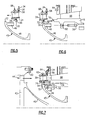
Figure 2 is a front view of an example exit guide vane. -
Figure 3 is a cross-sectional view of an example exit guide vane mounted within an example gas turbine engine. -
Figure 4 is an enlarged front view of an example interface between a tab of the exit guide vane and a slot on a diffuser assembly. -
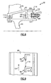
Figure 5 is a cross-section of an example exit guide vane prior to assembly to a thrust balance seal. -
Figure 6 is a cross-section of an example exit guide vane and thrust balance seal being mounted to a diffuser case. -
Figure 7 is a cross-sectional view of the example exit guide vane mounted to the diffuser. -
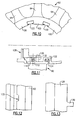
Figure 8 is a cross-sectional view of another example exit guide vane mounted to an example diffuser case. -
Figure 9 is a top view of a portion of the example diffuser case. -
Figure 10 is a front view of a portion of the example exit guide vane. -
Figure 11 is a cross-sectional view of an example interface between a stator case and the example exit guide vane. -
Figure 12 is a front view of a slot in the example exit guide vane. -
Figure 13 is a front view of a lug in the example stator case. - Referring to
Figure 1 , an examplegas turbine engine 10 includes afan 12, a compressor module 14 that compresses incoming air that is supplied to acombustor module 18. Exhaust gases generated in thecombustor module 18 are exhausted through aturbine module 20 that in turn drives the compressor module 14. Exhaust gases are then directed through anexhaust nozzle assembly 22. Air from the compressor module 14 proceeds through an exit guide vane that removes any swirl from the air flow. Following the exit guide vane, the diffuser assembly (not shown) conditions the airflow by causing a decrease in velocity and an increase in pressure prior to entering thecombustor module 18. The diffuser assembly can experience severe temperature fluctuations that can cause differing amounts of thermal growth within the same assembly. - Referring to
Figure 2 , prior to entering the diffuser assembly, air flow travels through anexit guide vane 24. Theexit guide vane 24 is static and defines an air flow path from the last rotating compressor module element to the diffuser assembly. The exampleexit guide vane 24 includes anouter ring 26 spaced radially apart from aninner ring 28. A plurality ofvanes 30 extends radially within the space between theinner ring 28 and theouter ring 26. Theinner ring 28 includes aninner flange 32 that is utilized for mounting and securing the exit guide vane 24 axially. Theouter ring 26 includes a plurality oftabs 34 spaced circumferentially apart adistance 39. Thetabs 34 engage a mating element for securing theexit guide vane 24 against undesired rotation. The exampleexit guide vane 24 includes 12tabs 34 that are spaced circumferential apart. Except for anindexing tab 35 each of thetabs 34 are spaced anequal distance 39 apart. Theindexing tab 35 is spaced adistance tabs 34 to provide a key that provides for a desired circumferential orientation. - Referring to
Figure 3 , theexit guide vane 24 is disposed forward of adiffuser assembly 16. Athrust balance seal 46 is attached to thediffuser assembly 16 through a plurality of bolted connections. One bolted connection is shown and includes abolt 50 that extends through an opening 52 and is engaged within a threadedhole 48 of thethrust balance seal 46. Theflange 32 of theexit guide vane 24 is held between thediffuser assembly 16 and alip 72 of thethrust balance seal 46. No bolted connection or snaps are provided between theexit guide vane 24 and thediffuser assembly 16. Further, the bolted connection between thediffuser assembly 16 and thethrust balance seal 46 is disposed outside of any primary or secondary air flows. For this reason, the bolted connection does not cause undesired disruptions in the air flow. - Referring to
Figure 4 with continuing reference toFigure 3 , thetabs 34, of theexit guide vane 24 are received within acorresponding slot 64 of thediffuser assembly 16, one of which is shown inFigure 4 . The interface between thetabs 34 and theslots 64 secures theexit guide vane 24 against rotation relative to thediffuser assembly 16. Theslot 64 is spaced radially apart adistance 65 from theouter ring 26 to provide space for relative radial movement between thediffuser assembly 16 and theexit guide vane 24 caused by, for example thermal expansion. - Referring to
Figure 3 , arotor 42 includes a plurality ofair foils 44 that rotates relative to the staticexit guide vane 24 andthrust balance seal 46. Anaft rotor hub 40 includes aknife edge 47 that abuts aseal 54 that is supported on an inner diameter of theexit guide vane 24. - The
exit guide vane 24 abuts thediffuser assembly 16 radially inward and outward of anair flow path 66. The radially inward and outward contact between theexit guide vane 24 and thediffuser assembly 16 are leakage paths that are sealed by anouter seal 58 and aninner seal 56. The outer andinner seals exit guide vane 24. The outer andinner seals diffuser assembly 16. The example seals 58, 56 include a "W" shape, however other seal configuration as are known are within the contemplation for use with the exampleexit guide vane 24. - The
exit guide vane 24 also includes apiston ring seal 62 that cooperates with a seal land on thecompressor case 60. Thepiston ring seal 62 is disposed about an outer circumference of theexit guide vane 24 and is biased radially outward to provide the desired seal and constraint of air flow. - Referring to
Figure 5 , assembly of theexit guide vane 24 to thediffuser assembly 16 includes the initial step of inserting thethrust balance seal 46 within the inner diameter of theexit guide vane 24. Thethrust balance seal 46 is received within the inner diameter of theexit guide vane 24 such that thelip 72 abuts theinner diameter flange 32. Theouter seal 58 and theinner seal 56 are installed within corresponding annular pockets to complete the initial subassembly of theexit guide vane 24. - Referring to
Figure 6 , thethrust balance seal 46 is bolted to thediffuser assembly 16. Thediffuser assembly 16 includes anopening 52 for abolt 50. Thebolt 50 is threaded into the threadedopening 48 within thethrust balance seal 46. The example position of the bolted connection is illustrated substantially adjacent an outer portion of thediffuser assembly 16. Other positions of the bolted connection that ease assembly are also possible. The bolted connection is however always disposed on a back or non-airflow side of thethrust balance seal 46. - Securement of the
thrust balance seal 46 to thediffuser assembly 16 traps theflange 32 of theexit guide vane 24 between thelip 72 of thethrust balance seal 46 and theforward surface 70 of thediffuser assembly 16. Theflange 32 is held in place between thediffuser assembly 16 and thethrust balance seal 46 and constrains forward axial movement of theexit guide vane 24. Circumferential movement of theexit guide vane 24 is constrained by the interface between thetabs 34 and the correspondingslots 64 on thediffuser assembly 16. Theslots 64 are spaced radially outboard from theouter ring 26 of theexit guide vane 24 to provide room to accommodate any relative expansion between thediffuser assembly 16 and theexit guide vane 24. - Referring to
Figure 7 , with theexit guide vane 24 and thethrust balance seal 46 secured to thediffuser assembly 16, therotor 42 andaft rotor hub 40 can be assembled as required to engage and seal against the surfaces of theexit guide vane 24 and thethrust balance seal 46. The pistonring seal land 60 seals against thepiston ring 62 disposed within an annular groove on the outer circumferences of theexit guide vane 24. - The interface between the
rotor 42 thethrust balance seal 46 and theexit guide vane 24 include no bolted connections that are disposed within an air flow path. Seals are provided to minimize leakage or calibrate air flow as is desired. The outer andinner seals air flow path 66 defined by the diffuser assembly. - The
seal 54 provides a calibrated leakage of air flow along theforward surface 45 of thethrust balance seal 46. However, no mounting connection is disposed along theforward surface 45 that could disrupt the desired air flow. - Referring to
Figure 8 , another exampleexit guide vane 92 is mounted adjacent to adiffuser case 102 and is held in place by athrust balance seal 96. Thethrust balance seal 96 is attached to thediffuser case 102 by a bolted connection including abolt 104 extending through anopening 106 in thethrust balance seal 96 and engaged to threadedopening 108 within thediffuser case 102. - In this example, the
thrust balance seal 96 is secured to thediffuser case 102 before theexit guide vane 92. Theexit guide vane 92 is then assembled onto thethrust balance seal 96. Theexit guide vane 92 is secured to thethrust balance seal 96 by a plurality oftabs 100 that interfit into correspondinglugs 98. Theexit guide vane 92 includes thetabs 100 and the thrust balance seal includes thelugs 98. Aseal 110 is disposed within apocket 114 of theexit guide vane 92 that contacts an outer surface of thethrust balance seal 96. Air flows over and throughvanes 94 and into thediffuser case 102 along asurface 116. The bolted connection between thethrust balance seal 96 and thediffuser case 102 is disposed below thesurface 116 so as to not interfere with air flow. - Referring to
Figures 9 and10 with continued reference toFigure 8 , thelugs 98 are "L" shaped and are spaced circumferentially adistance 118. The exampleexit guide vane 92 include thetabs 100 that are spaced apart adistance 120. Thedistance 120 corresponds with acircumferential length 122 of thelugs 98. Assembly of theexit guide vane 92 includes sliding theexit guide vane 92 over thethrust balance seal 96 such that thelugs 98 slide through the space between thetabs 100. Once theexit guide vane 92 is disposed against thediffuser case 102, it is rotated so that thetabs 100 are received aft of thefront portion 126 of eachcorresponding lug 98. Once thetabs 100 are interlocked with the correspondinglug 98, movement is constrained in a first circumferential direction and the forward axial direction. - Referring to
Figures 11, 12 and 13 , a high pressurecompressor stator case 128 includes alug 130 that is received within aslot 132 of theexit guide vane 92. Thelug 130 prevents rotation of theexit guide vane 92 in a second circumferential direction opposite from the first circumferential direction. Thelug 130,slot 132 interface in combination with thetab 100 and lug 98 interface between thethrust balance seal 96 and theexit guide vane 92 prevent rotation. Theexit guide vane 92 is, however, free to expand and contract radially relative to thediffuser case 102, thrustbalance seal 96 and thestator case 128. This interface and securement configuration accommodates radial thermal expansion and displacement that can occur during operation. - Although a preferred embodiment of this invention has been disclosed, a worker of ordinary skill in this art would recognize that certain modifications would come within the scope of this invention. For that reason, the following claims should be studied to determine the true scope and content of this invention.
Claims (21)
- An exit guide vane mounting assembly comprising:a diffuser case (16;102) defining an air flow path;a thrust balance seal (46;96) attached to the diffuser; andan exit guide vane (24;92) mounted adjacent to the diffuser case (16;102) for guiding air flow into the air flow path, wherein the exit guide vane (24;92) is secured adjacent to the diffuser (16;102) without a fastener.
- The assembly as recited in claim 1, wherein the thrust balance seal (46;96) is secured to the diffuser case (16;102) with a fastener (50; 104) that is disposed outside of the air flow path.
- The assembly as recited in claim 2, wherein the diffuser case (16;102) includes a surface defining a flow surface of the air flow path and the fastener (50;104) is disposed on a side opposite the flow surface.
- The assembly as recited in any preceding claim, wherein the exit guide vane (24;92) is held in place between a portion of the thrust balance seal (46;96) and the diffuser case (16;102).
- The assembly as recited in any preceding claim, including an anti-rotation feature disposed on one of the diffuser case (16;102) and thrust balance seal (46;96) for preventing rotation of the exit guide vane (24;92) relative to the diffuser case (16;102).
- The assembly as recited in claim 5, wherein the anti-rotation feature comprises a lug (98) disposed on one of the thrust balance seal (96) and the diffuser (102) that is engageable with a tab (100) disposed on the exit guide vane (92).
- An exit guide vane mounting assembly comprising:a diffuser case (16) including a plurality of lugs spaced circumferentially about an axis;a thrust balance seal mountable to the diffuser case; andan exit guide vane assembly (24) mounted against the diffuser case (16) and held in place by the thrust balance seal (46), where the exit guide vane (24) includes a plurality of tabs (34) engageable with the plurality of lugs on the diffuser case (16) for inhibiting rotation of the exit guide vane (22) relative to the diffuser case (16).
- The assembly as recited in claim 7, wherein the exit guide vane (24) includes an inner flange (32) secured between the thrust balance seal (46) and the diffuser case (16).
- The assembly as recited in claim 7 or 8, wherein the plurality of tabs (34) extend from an outer perimeter of the exit guide vane (24).
- The assembly as recited in claim 9, wherein each of the plurality of tabs (34) fits against a corresponding one of the plurality of lugs on the diffuser case (16).
- The assembly as recited in claim 10, wherein at least one (35) of the plurality of tabs (34) is spaced circumferentially apart a distance different than the other plurality of tabs (34) for defining a circumferential relationship between the exit guide vane (24) and the diffuser case (16).
- The assembly as recited in any of claims 7 to 11, wherein the thrust balance seal (46) includes a threaded opening (48) disposed on a back side not exposed to incoming flow for receiving a fastener (50) for mounting the thrust balance seal (46) to the diffuser case (16).
- The assembly as recited in any of claims 7 to 12, including an inner seal (56) and an outer seal (58) between the exit guide vane (24) and the diffuser case (16).
- The assembly as recited in claim 13, wherein the inner seal (56) and the outer seal (58) bias the exit guide vane (24) in a direction away from the diffuser case (16).
- The assembly as recited in any of claims 7 to 14, wherein the exit guide vane (24) includes an inner ring (28) and an outer ring (26) spaced radially apart from the inner ring (28) and a plurality of vanes (30) extending radially between the inner ring (28) and the outer ring (26).
- The assembly as recited in claim 15, including a ring seal (56) disposed on the outer ring (26) of the exit guide vane (24).
- The assembly as recited in claim 15 or 16, including a seal (54) disposed on the inner ring (28) for sealing with a rotating member.
- An exit guide vane mounting assembly comprising:an exit guide vane (92) including an outer rim spaced radially apart from an inner rim and a plurality of vanes extending radially from the inner rim to the outer rim;a thrust balance seal (96) secured to a diffuser case (102), wherein the thrust balance seal (96) includes a plurality of lugs (98); anda plurality of tabs (100) disposed on the inner rim that are engageable with a corresponding one of the plurality of lugs (98) on the thrust balance seal (96) for securing the exit guide vane (92) against the diffuser case (102).
- The assembly as recited in claim 18, wherein the tabs (100) of the exit guide vane (92) are rotated to engage the lugs (98) on the thrust balance seal (96).
- The assembly as recited in claim 18 or 19, wherein the exit guide vane (92) includes a slot (132) and a stator case (128) includes an extension (130) received within the slot (132) for securing the exit guide vane (92) from movement in a circumferential direction.
- The assembly as recited in claim 18, 19 or 20, wherein the thrust balance seal (96) is attached to the diffuser case (102) by a fastener (104) that is disposed on a side of the diffuser case (102) that does not define a surface of an air flow path.
Applications Claiming Priority (1)
| Application Number | Priority Date | Filing Date | Title |
|---|---|---|---|
| US11/641,326 US7819622B2 (en) | 2006-12-19 | 2006-12-19 | Method for securing a stator assembly |
Publications (2)
| Publication Number | Publication Date |
|---|---|
| EP1939404A2 true EP1939404A2 (en) | 2008-07-02 |
| EP1939404A3 EP1939404A3 (en) | 2011-12-21 |
Family
ID=39197155
Family Applications (1)
| Application Number | Title | Priority Date | Filing Date |
|---|---|---|---|
| EP07254892A Withdrawn EP1939404A3 (en) | 2006-12-19 | 2007-12-17 | Stator assembly |
Country Status (2)
| Country | Link |
|---|---|
| US (1) | US7819622B2 (en) |
| EP (1) | EP1939404A3 (en) |
Cited By (5)
| Publication number | Priority date | Publication date | Assignee | Title |
|---|---|---|---|---|
| WO2011018072A3 (en) * | 2009-08-14 | 2011-09-15 | Mtu Aero Engines Gmbh | Fastening element for a guide blade ring of a turbomachine |
| EP2466074A1 (en) * | 2010-12-15 | 2012-06-20 | MTU Aero Engines GmbH | Gas turbine engine with piston ring sealing device |
| EP2949872A1 (en) * | 2014-05-27 | 2015-12-02 | Siemens Aktiengesellschaft | Turbomachine with a seal for separating working fluid and coolant fluid of the turbomachine and use of the turbomachine |
| EP3034797A1 (en) * | 2014-12-15 | 2016-06-22 | United Technologies Corporation | High compressor exit guide vane assembly to pre-diffuser junction |
| WO2020263395A1 (en) * | 2019-06-28 | 2020-12-30 | Siemens Aktiengesellschaft | Seal assembly in a gas turbine engine |
Families Citing this family (19)
| Publication number | Priority date | Publication date | Assignee | Title |
|---|---|---|---|---|
| US20130004314A1 (en) * | 2011-06-29 | 2013-01-03 | United Technologies Corporation | Radial spline arrangement for lpt vane clusters |
| US8961125B2 (en) | 2011-12-13 | 2015-02-24 | United Technologies Corporation | Gas turbine engine part retention |
| US9255487B2 (en) | 2012-01-31 | 2016-02-09 | United Technologies Corporation | Gas turbine engine seal carrier |
| US9051849B2 (en) | 2012-02-13 | 2015-06-09 | United Technologies Corporation | Anti-rotation stator segments |
| US9447695B2 (en) * | 2012-03-01 | 2016-09-20 | United Technologies Corporation | Diffuser seal for geared turbofan or turboprop engines |
| US9851008B2 (en) * | 2012-06-04 | 2017-12-26 | United Technologies Corporation | Seal land for static structure of a gas turbine engine |
| US9200530B2 (en) | 2012-07-20 | 2015-12-01 | United Technologies Corporation | Radial position control of case supported structure |
| US9957799B2 (en) | 2012-09-19 | 2018-05-01 | United Technologies Corporation | Balance ring for gas turbine engine |
| EP2846001B1 (en) * | 2013-09-06 | 2023-01-11 | MTU Aero Engines AG | Assembly and disassembly methods of a rotor of a gas turbine and corresponding tool |
| EP3044427B8 (en) | 2013-09-12 | 2021-04-07 | Raytheon Technologies Corporation | Gas turbine engine and corresponding method for regulating blade tip clearance |
| US10301957B2 (en) * | 2014-12-17 | 2019-05-28 | United Technologies Corporation | Pinned seal |
| US20160265549A1 (en) * | 2015-03-09 | 2016-09-15 | Caterpillar Inc. | Compressor assembly having dynamic diffuser ring retention |
| US11428241B2 (en) * | 2016-04-22 | 2022-08-30 | Raytheon Technologies Corporation | System for an improved stator assembly |
| WO2016179608A2 (en) | 2016-04-29 | 2016-11-10 | Stein Seal Company | Intershaft seal with asymmetric sealing ring |
| DE102017105760A1 (en) * | 2017-03-17 | 2018-09-20 | Man Diesel & Turbo Se | Gas turbine, vane ring of a gas turbine and method of making the same |
| DE102017207640A1 (en) * | 2017-05-05 | 2018-11-08 | Rolls-Royce Deutschland Ltd & Co Kg | Flow guiding device and method for forming a flow guiding device |
| US11384936B2 (en) * | 2019-04-05 | 2022-07-12 | Raytheon Technologies Corporation | Pre-diffuser for a gas turbine engine |
| US11136995B2 (en) | 2019-04-05 | 2021-10-05 | Raytheon Technologies Corporation | Pre-diffuser for a gas turbine engine |
| US11371704B2 (en) * | 2019-04-05 | 2022-06-28 | Raytheon Technologies Corporation | Pre-diffuser for a gas turbine engine |
Family Cites Families (9)
| Publication number | Priority date | Publication date | Assignee | Title |
|---|---|---|---|---|
| US3067983A (en) * | 1958-07-01 | 1962-12-11 | Gen Motors Corp | Turbine mounting construction |
| DE3627306A1 (en) * | 1986-02-28 | 1987-09-03 | Mtu Muenchen Gmbh | DEVICE FOR VENTILATING ROTOR COMPONENTS FOR COMPRESSORS OF GAS TURBINE ENGINE PLANTS |
| US6287091B1 (en) * | 2000-05-10 | 2001-09-11 | General Motors Corporation | Turbocharger with nozzle ring coupling |
| US6364606B1 (en) * | 2000-11-08 | 2002-04-02 | Allison Advanced Development Company | High temperature capable flange |
| US6517313B2 (en) * | 2001-06-25 | 2003-02-11 | Pratt & Whitney Canada Corp. | Segmented turbine vane support structure |
| DE10318852A1 (en) | 2003-04-25 | 2004-11-11 | Rolls-Royce Deutschland Ltd & Co Kg | Main gas duct inner seal of a high pressure turbine |
| US6916154B2 (en) * | 2003-04-29 | 2005-07-12 | Pratt & Whitney Canada Corp. | Diametrically energized piston ring |
| US7300246B2 (en) * | 2004-12-15 | 2007-11-27 | Pratt & Whitney Canada Corp. | Integrated turbine vane support |
| US7329096B2 (en) * | 2005-10-18 | 2008-02-12 | General Electric Company | Machine tooled diaphragm partitions and nozzles |
-
2006
- 2006-12-19 US US11/641,326 patent/US7819622B2/en active Active
-
2007
- 2007-12-17 EP EP07254892A patent/EP1939404A3/en not_active Withdrawn
Cited By (10)
| Publication number | Priority date | Publication date | Assignee | Title |
|---|---|---|---|---|
| WO2011018072A3 (en) * | 2009-08-14 | 2011-09-15 | Mtu Aero Engines Gmbh | Fastening element for a guide blade ring of a turbomachine |
| EP2466074A1 (en) * | 2010-12-15 | 2012-06-20 | MTU Aero Engines GmbH | Gas turbine engine with piston ring sealing device |
| EP2949872A1 (en) * | 2014-05-27 | 2015-12-02 | Siemens Aktiengesellschaft | Turbomachine with a seal for separating working fluid and coolant fluid of the turbomachine and use of the turbomachine |
| WO2015180945A1 (en) * | 2014-05-27 | 2015-12-03 | Siemens Aktiengesellschaft | Turbomachine with a seal for separating working fluid and coolant fluid of the turbomachine and use of the turbomachine |
| CN106414905A (en) * | 2014-05-27 | 2017-02-15 | 西门子股份公司 | Turbomachine with a seal for separating working fluid and coolant fluid of the turbomachine and use of the turbomachine |
| RU2664750C2 (en) * | 2014-05-27 | 2018-08-22 | Сименс Акциенгезелльшафт | Turbomashine with seal for separation of working environment and cooling environment of turbomashine and application of turbomashine |
| EP3034797A1 (en) * | 2014-12-15 | 2016-06-22 | United Technologies Corporation | High compressor exit guide vane assembly to pre-diffuser junction |
| US10161414B2 (en) | 2014-12-15 | 2018-12-25 | United Technologies Corporation | High compressor exit guide vane assembly to pre-diffuser junction |
| WO2020263395A1 (en) * | 2019-06-28 | 2020-12-30 | Siemens Aktiengesellschaft | Seal assembly in a gas turbine engine |
| US11834953B2 (en) | 2019-06-28 | 2023-12-05 | Siemens Energy Global GmbH & Co. KG | Seal assembly in a gas turbine engine |
Also Published As
| Publication number | Publication date |
|---|---|
| US20080145217A1 (en) | 2008-06-19 |
| EP1939404A3 (en) | 2011-12-21 |
| US7819622B2 (en) | 2010-10-26 |
Similar Documents
| Publication | Publication Date | Title |
|---|---|---|
| EP1939404A2 (en) | Stator assembly | |
| KR102599936B1 (en) | Gas turbine ring assembly comprising ring segments having integrated interconnecting seal | |
| EP1240411B1 (en) | Split ring for tip clearance control | |
| US9328926B2 (en) | Segmented combustion chamber head | |
| EP1164250B1 (en) | Floating connector for an impingement insert | |
| US10161257B2 (en) | Turbine slotted arcuate leaf seal | |
| EP1036255B1 (en) | Seal assembly for a gas turbine engine | |
| EP2325438B1 (en) | Seal plates for directing airflow through a turbine section of an engine and turbine sections | |
| EP2564032B1 (en) | Component of a turbine with leaf seals and method for sealing against leakage between a vane and a carrier element | |
| EP1930552B1 (en) | Turbine assembly to facilitate reducing losses in turbine engines | |
| EP3604761B1 (en) | Turbine housing assembly and supercharger provided with same | |
| EP2372084A2 (en) | Turbomachine Rotor Cooling | |
| US10760441B2 (en) | Turbine for a turbine engine | |
| EP2267279B1 (en) | A guide vane assembly | |
| US11525367B2 (en) | Sealing between a rotor disc and a stator of a turbomachine | |
| WO2014166676A1 (en) | Impingement ring element attachment and sealing | |
| US11585230B2 (en) | Assembly for a turbomachine | |
| EP2904241A2 (en) | Combustor seal mistake-proofing for a gas turbine engine | |
| US9982783B2 (en) | Aircraft gas turbine with a seal for sealing an igniter plug on the combustion chamber wall of a gas turbine | |
| EP2372085A2 (en) | Internal reaction steam turbine cooling arrangement | |
| EP3287605B1 (en) | Rim seal for gas turbine engine | |
| EP4019742B1 (en) | A sealing assembly for a vane set of a gas turbine engine and gas turbine engine comprising such a sealing assembly | |
| EP3926141B1 (en) | Gas turbine stator vane with sealing member and method for modifying a gas turbine stator vane | |
| CN116888346A (en) | turbine seal ring | |
| US12467374B2 (en) | Turbine nozzle guide vane comprising an annular sealing element |
Legal Events
| Date | Code | Title | Description |
|---|---|---|---|
| PUAI | Public reference made under article 153(3) epc to a published international application that has entered the european phase |
Free format text: ORIGINAL CODE: 0009012 |
|
| AK | Designated contracting states |
Kind code of ref document: A2 Designated state(s): AT BE BG CH CY CZ DE DK EE ES FI FR GB GR HU IE IS IT LI LT LU LV MC MT NL PL PT RO SE SI SK TR |
|
| AX | Request for extension of the european patent |
Extension state: AL BA HR MK RS |
|
| PUAL | Search report despatched |
Free format text: ORIGINAL CODE: 0009013 |
|
| AK | Designated contracting states |
Kind code of ref document: A3 Designated state(s): AT BE BG CH CY CZ DE DK EE ES FI FR GB GR HU IE IS IT LI LT LU LV MC MT NL PL PT RO SE SI SK TR |
|
| AX | Request for extension of the european patent |
Extension state: AL BA HR MK RS |
|
| RIC1 | Information provided on ipc code assigned before grant |
Ipc: F01D 11/00 20060101ALI20111115BHEP Ipc: F01D 9/02 20060101AFI20111115BHEP |
|
| 17P | Request for examination filed |
Effective date: 20120620 |
|
| AKX | Designation fees paid |
Designated state(s): DE GB |
|
| STAA | Information on the status of an ep patent application or granted ep patent |
Free format text: STATUS: THE APPLICATION HAS BEEN WITHDRAWN |
|
| 18W | Application withdrawn |
Effective date: 20140206 |