EP1939090A1 - Machine for packaging articles into box-like containers - Google Patents
Machine for packaging articles into box-like containers Download PDFInfo
- Publication number
- EP1939090A1 EP1939090A1 EP07122230A EP07122230A EP1939090A1 EP 1939090 A1 EP1939090 A1 EP 1939090A1 EP 07122230 A EP07122230 A EP 07122230A EP 07122230 A EP07122230 A EP 07122230A EP 1939090 A1 EP1939090 A1 EP 1939090A1
- Authority
- EP
- European Patent Office
- Prior art keywords
- blank
- machine
- station
- folding
- flaps
- Prior art date
- Legal status (The legal status is an assumption and is not a legal conclusion. Google has not performed a legal analysis and makes no representation as to the accuracy of the status listed.)
- Granted
Links
- 238000004806 packaging method and process Methods 0.000 title claims abstract description 6
- 230000000284 resting effect Effects 0.000 claims description 10
- 239000000853 adhesive Substances 0.000 claims description 3
- 230000001070 adhesive effect Effects 0.000 claims description 3
- 238000004026 adhesive bonding Methods 0.000 claims 2
- 230000005484 gravity Effects 0.000 claims 1
- 238000004519 manufacturing process Methods 0.000 description 8
- 230000036961 partial effect Effects 0.000 description 5
- 230000008901 benefit Effects 0.000 description 4
- 239000002390 adhesive tape Substances 0.000 description 3
- 230000004913 activation Effects 0.000 description 2
- 238000005452 bending Methods 0.000 description 2
- 230000007423 decrease Effects 0.000 description 2
- 238000004804 winding Methods 0.000 description 2
- 230000003247 decreasing effect Effects 0.000 description 1
- 230000000694 effects Effects 0.000 description 1
- 230000002349 favourable effect Effects 0.000 description 1
- 230000002452 interceptive effect Effects 0.000 description 1
- 230000000670 limiting effect Effects 0.000 description 1
- 238000000034 method Methods 0.000 description 1
- 230000001681 protective effect Effects 0.000 description 1
- 230000002829 reductive effect Effects 0.000 description 1
- 230000003252 repetitive effect Effects 0.000 description 1
- 238000007789 sealing Methods 0.000 description 1
- 230000009897 systematic effect Effects 0.000 description 1
- 230000000007 visual effect Effects 0.000 description 1
Images


Classifications
-
- B—PERFORMING OPERATIONS; TRANSPORTING
- B65—CONVEYING; PACKING; STORING; HANDLING THIN OR FILAMENTARY MATERIAL
- B65B—MACHINES, APPARATUS OR DEVICES FOR, OR METHODS OF, PACKAGING ARTICLES OR MATERIALS; UNPACKING
- B65B5/00—Packaging individual articles in containers or receptacles, e.g. bags, sacks, boxes, cartons, cans, jars
- B65B5/02—Machines characterised by incorporation of means for making the containers or receptacles
- B65B5/024—Machines characterised by incorporation of means for making the containers or receptacles for making containers from preformed blanks
-
- B—PERFORMING OPERATIONS; TRANSPORTING
- B65—CONVEYING; PACKING; STORING; HANDLING THIN OR FILAMENTARY MATERIAL
- B65B—MACHINES, APPARATUS OR DEVICES FOR, OR METHODS OF, PACKAGING ARTICLES OR MATERIALS; UNPACKING
- B65B43/00—Forming, feeding, opening or setting-up containers or receptacles in association with packaging
- B65B43/12—Feeding flexible bags or carton blanks in flat or collapsed state; Feeding flat bags connected to form a series or chain
- B65B43/14—Feeding individual bags or carton blanks from piles or magazines
- B65B43/145—Feeding carton blanks from piles or magazines
-
- B—PERFORMING OPERATIONS; TRANSPORTING
- B65—CONVEYING; PACKING; STORING; HANDLING THIN OR FILAMENTARY MATERIAL
- B65B—MACHINES, APPARATUS OR DEVICES FOR, OR METHODS OF, PACKAGING ARTICLES OR MATERIALS; UNPACKING
- B65B65/00—Details peculiar to packaging machines and not otherwise provided for; Arrangements of such details
- B65B65/003—Packaging lines, e.g. general layout
Definitions
- boxing machines are designed for boxing articles or packs of articles of different kind (that is, more commonly, for packaging articles into box-like containers); in general and qualitative terms, the operations, that follow one another in similar machines include: picking up a flat folded tubular blank from a containing magazine, erecting the blank, so that it assumes a parallelepiped shape of rectangular section and vertical (horizontal) axis, introduction of articles or packs of articles into the erected blank, in vertical (horizontal) direction, folding the blank flaps and their mutual sealing, so as to define the bottom and a cover of a corresponding box of articles.
- the blanks are less resistant to bending, therefore the ones placed in the lower part of the stack can lose the planarity and assume a curved downward conformation, due to the weight resting on them.
- These drawbacks are amplified by increasing dimensions, and consequently weight, of the blanks.
- boxing machines of known type which include the introduction of articles in vertical direction
- the square blank is usually taken to the filling station by conveying means, which are aimed at maintaining, no matter of how the size changes, the bottom and the longitudinal medium line in alignment with two corresponding stationary planes, one horizontal and the other vertical.
- manipulating means aimed at introducing the articles into the boxes being formed and working in a position corresponding to the filling station, perform vertical strokes having constant maximum width, independently from the dimensions of the containers being used. Consequently, a production rate, which can be accepted for boxes of large dimensions, does not imply satisfying filling times for boxes of minimum dimensions, or anyway smaller, for which a higher production rate is normally expected. Therefore, the main object of the present invention is to solve successfully the above mentioned disadvantages, by conceiving a machine, that allows to reduce substantially the time necessary for the introduction of the articles into the erected blanks, especially for small sizes, obtaining in this way a more favorable production rate with respect to the solutions of known type.
- Another object of the invention is to propose a machine, whose station for feeding flat folded tubular blanks is provided with working means, capable of operating in best way also with blanks shaped to form square-section boxes, independently from the blanks size and weight, and which can store a considerable number of blanks, so as to offer high operation autonomy.
- a further object of the invention is to create a newly conceived machine for packaging articles into box-like containers, made in such a way, as to allow the operator's constant visual control of the box-like containers being formed (erecting of the tubular blank), filled and closed, making also simple and immediate a possible direct servicing for the stations, in which these steps are carried out.
- the machine being considered must be reliable, have an essential structure, high productivity at relatively low costs in comparison with the results to be obtained.
- the station 100 includes an in-depth storage magazine 110, aimed at containing at least a first stack P1 of blanks 1, formed by one of said packs supplied by the paper-transformation industry, suitably freed of ropes or strips, with which it was tied.
- the stack P1 is introduced into the in-depth storage magazine 110, with the blanks 1 arranged horizontal and placed on first, openable support means 111, situated in a position corresponding to the lower, open mouth 100A of the magazine 100.
- the in-depth storage magazine 100 is delimited peripherally by walls 115, adjustable in relation to the size, according to the plan dimensions of the blanks 1 and in alignment with fixed references of the machine M.
- the magazine 110 extends vertically to contain, besides the first stack P1, other two stacks P2, P3, situated at subsequent higher levels L2, L3 and supported by respective second and third openable support means 112, 113, preferably identical with the first ones.
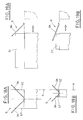
- Each of said openable support means 111, 112, 113 includes, for example a pair of oscillating, opposite support paddles 120, moving synchronously between a horizontal position, in which they support corresponding edges of the bottommost blank 1 of the relative stack ( Figures 5, 6 ), and a downward inclined position, in which the same blanks 1 are not held ( Figures 7, 8 ).
- the stacks P1, P2, P3 contained in the magazine 100 are mutually spaced apart, so as to leave sufficient space for the movement of the respective oscillating support paddles 120.
- a platform 130 made move vertically by means, not shown, for example electronically controlled, aimed at defining prefixed placing levels for the same platform.
- Picking up means 140 likewise provided in the station 100, move horizontally between two extreme positions E1, E2, in the first of which they are situated above the platform 130, while in the second one they are situated clear of it, in a position corresponding to the erecting station 2.
- the above mentioned picking up means 140 include for example, a slide 141, engaged in a guide 142 extending horizontally between said stations 100 and 2, provided with a shaped arm 143, cantilevered toward said platform 130 area and provided with suction cups 144, connected to a vacuum source.
- conveying means 150 are advantageously connected to the in-depth storage magazine 110, situated above it and aimed at feeding the stacks of blanks 1 into the same magazine 110 and at arranging them resting on the openable support means, situated at a higher level (relatively to the Figures, the one indicated with L3 and corresponding to the support means 113).
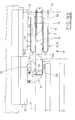
- the conveying means 150 ( Figures 3 , 4 , 10, 14 ) include, for example a support plate 151, external with respect to the magazine 110, situated at a level L5, suitably higher than the level L3 of the cited openable support means 113 ( Figure 12 ), and aimed at holding at least one of said stacks of blanks 1, placed in position, for example, manually by an operator.
- the support plate 151 is provided with centering walls 152A, 152B, which extend up to enter partially into the magazine 110 and are suitably adjustable in relation to the size, according to the dimensions of the blanks 1 and in alignment with said fixed references.
- At least one retractable blade 153 aligned with the support plate 151, at a level L4, slightly lower than level L5 of the bearing pad ( Figure 12 ), is provided in a position corresponding to an edge of said blanks 1, to continue the support plate 151.
- the retractable blade 153 is moved, by the action of an actuator, not shown, between a working position Y1, in which it is aimed at supporting, above the magazine 110, a stack of blanks 1, coming from the support plate 151, due to manual action of said operator ( Figure 10 ), and a rest position Y2, in which it is clear of the surface occupied by the same blanks 1, to allow them to enter the magazine 110, ( Figure 14 ), as it will be better described in the following.
- the support plate 151 and the retractable blade 153 extend perpendicular to the movement direction of the conveying line 103 of the machine M and of the slide 141; the support plate 151 extends at the machine side occupied by the operator, but obviously, such arrangement is not binding, because it can also be parallel to the above mentioned direction; naturally, in this case it would also be necessary to change the arrangement of the retractable blade 153.
- Figure 11 shows a constructive peculiarity of the support plate 151, which is inclined by some degrees with respect to the horizontal, so that the stack of blanks 1, resting thereon, remains in a position set by a fixed reference F (defined by the inner surface of the adjacent centering wall 152A), situated on the side with the retractable blade 153; this inclination facilitates also the stack transferring toward the retractable blade 153, keeping raised the opposite side, so as to prevent the stack bottommost blanks from getting stuck against the support paddles due to their slight downward bending ( Figure 12 ).
- a fixed reference F defined by the inner surface of the adjacent centering wall 152A
Abstract
Description
- The present invention relates to the technical field of boxing machines. As it is known, boxing machines are designed for boxing articles or packs of articles of different kind (that is, more commonly, for packaging articles into box-like containers); in general and qualitative terms, the operations, that follow one another in similar machines include: picking up a flat folded tubular blank from a containing magazine, erecting the blank, so that it assumes a parallelepiped shape of rectangular section and vertical (horizontal) axis, introduction of articles or packs of articles into the erected blank, in vertical (horizontal) direction, folding the blank flaps and their mutual sealing, so as to define the bottom and a cover of a corresponding box of articles. It is understood that some of these operations can be performed in a different order than the cited one, or include more phases (for example, it is possible that first the flaps forming the box bottom are folded, then the articles are introduced into the erected blank and next, the flaps defining the box cover are folded), according to the type of the machine.
It is known in the boxing machines, that cross-section of the box to be obtained is rectangular, and in some cases even square.
In the last case, it occurs in the feeding station magazine that the diagonally opposite pre-creasing lines in flat configuration, situated at the blank center, are exactly one over another, unlike in the rectangular section case, in which they are shifted.
For this reason, the blanks are less resistant to bending, therefore the ones placed in the lower part of the stack can lose the planarity and assume a curved downward conformation, due to the weight resting on them.
These drawbacks are amplified by increasing dimensions, and consequently weight, of the blanks.
In boxing machines of known type, which include the introduction of articles in vertical direction, the square blank is usually taken to the filling station by conveying means, which are aimed at maintaining, no matter of how the size changes, the bottom and the longitudinal medium line in alignment with two corresponding stationary planes, one horizontal and the other vertical. In this way, manipulating means, aimed at introducing the articles into the boxes being formed and working in a position corresponding to the filling station, perform vertical strokes having constant maximum width, independently from the dimensions of the containers being used. Consequently, a production rate, which can be accepted for boxes of large dimensions, does not imply satisfying filling times for boxes of minimum dimensions, or anyway smaller, for which a higher production rate is normally expected.
Therefore, the main object of the present invention is to solve successfully the above mentioned disadvantages, by conceiving a machine, that allows to reduce substantially the time necessary for the introduction of the articles into the erected blanks, especially for small sizes, obtaining in this way a more favorable production rate with respect to the solutions of known type.
Another object of the invention is to propose a machine, whose station for feeding flat folded tubular blanks is provided with working means, capable of operating in best way also with blanks shaped to form square-section boxes, independently from the blanks size and weight, and which can store a considerable number of blanks, so as to offer high operation autonomy.
A further object of the invention is to create a newly conceived machine for packaging articles into box-like containers, made in such a way, as to allow the operator's constant visual control of the box-like containers being formed (erecting of the tubular blank), filled and closed, making also simple and immediate a possible direct servicing for the stations, in which these steps are carried out. Moreover, the machine being considered must be reliable, have an essential structure, high productivity at relatively low costs in comparison with the results to be obtained.
The above mentioned objects are obtained in accordance with the contents of the claims. - The characteristic features of the invention, not appearing from what has been just said, will be better pointed out in the following, in accordance with the contents of claims and with help of the enclosed figures, in which:
-
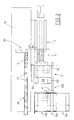
Figure 1 is a partial and schematic, lateral view of the machine, carrying out the method proposed by the present invention, in a preferred embodiment; -
Figure 2 is a partial and schematic, top view of the machine ofFigure 1 ; -
Figures 3 and4 are perspective views of the station for feeding blanks of the machine, from the operator' side and the opposite one, respectively; -
Figures 5 and 6 are schematic views, in vertical section, of the feeding station in two work steps, while picking up the blanks; -
Figures 7, 8 ,9 are the same views asFigures 5 and 6 , of the subsequent steps of supplying of blanks to the picking up means situated in the station; -
Figure 10 is a top view ofFigure 9 ; -
Figure 11 is a section view, taken along the plane XI-XI ofFigure 10 ; -
Figure 12 is a section view, taken along the plane XII-XII ofFigure 10 ; -
Figure 13 is the same view asFigures 5, 6 ,7, 8 ,9 , of the magazine loading step; -
Figure 14 is a top view ofFigure 13 ; -
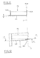
Figures 15A - 15B are enlarged, front views XV-XV ofFigure 1 , that is a unit for erecting a tubular blank, in this case of maximum size, in two different, significant operation conditions; -
Figures 15C - 15D show the unit ofFigures 15A, 15B in two different, significant operation conditions, in relation to a tubular blank with minimum size; -
Figures 16A ,16B are enlarged, partial, top views of a detail ofFigure 1 , that is the above mentioned erecting unit, acting on a blank with maximum and minimum size, respectively, and driving and guiding means; -
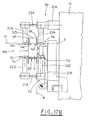
Figures 17A ,17B are section views, taken along the plane XVII-XVII ofFigure 1 , of an erected blank with maximum and minimum size, respectively; -
Figures 18A - 19A are front and lateral views of a fourth detail ofFigure 1 , that is means for folding the upper lateral flaps of an erected blank with maximum size, and an upper portion of the latter, respectively; -
Figures 18B - 19B are front and lateral views, respectively, of the fourth detail ofFigure 1 , that is means for folding the upper lateral flaps of an erected blank with minimum size, and an upper portion of the latter. - The
station 100 includes an in-depth storage magazine 110, aimed at containing at least a first stack P1 ofblanks 1, formed by one of said packs supplied by the paper-transformation industry, suitably freed of ropes or strips, with which it was tied.
The stack P1 is introduced into the in-depth storage magazine 110, with theblanks 1 arranged horizontal and placed on first, openable support means 111, situated in a position corresponding to the lower, open mouth 100A of themagazine 100.
The in-depth storage magazine 100 is delimited peripherally bywalls 115, adjustable in relation to the size, according to the plan dimensions of theblanks 1 and in alignment with fixed references of the machine M.
In the example shown in the enclosed Figures, themagazine 110 extends vertically to contain, besides the first stack P1, other two stacks P2, P3, situated at subsequent higher levels L2, L3 and supported by respective second and third openable support means 112, 113, preferably identical with the first ones.
Each of said openable support means 111, 112, 113 includes, for example a pair of oscillating,opposite support paddles 120, moving synchronously between a horizontal position, in which they support corresponding edges of the bottommost blank 1 of the relative stack (Figures 5, 6 ), and a downward inclined position, in which thesame blanks 1 are not held (Figures 7, 8 ).
With the described conformation of the openable support means 111, 112, 113, the stacks P1, P2, P3 contained in themagazine 100 are mutually spaced apart, so as to leave sufficient space for the movement of the respective oscillatingsupport paddles 120.
Below the in-depth storage magazine, there is aplatform 130, made move vertically by means, not shown, for example electronically controlled, aimed at defining prefixed placing levels for the same platform.
Picking up means 140, likewise provided in thestation 100, move horizontally between two extreme positions E1, E2, in the first of which they are situated above theplatform 130, while in the second one they are situated clear of it, in a position corresponding to the erectingstation 2.
The above mentioned picking upmeans 140 include for example, aslide 141, engaged in aguide 142 extending horizontally between saidstations shaped arm 143, cantilevered toward saidplatform 130 area and provided withsuction cups 144, connected to a vacuum source.
In the embodiment in question,conveying means 150 are advantageously connected to the in-depth storage magazine 110, situated above it and aimed at feeding the stacks ofblanks 1 into thesame magazine 110 and at arranging them resting on the openable support means, situated at a higher level (relatively to the Figures, the one indicated with L3 and corresponding to the support means 113).
The conveying means 150 (Figures 3 ,4 ,10, 14 ) include, for example asupport plate 151, external with respect to themagazine 110, situated at a level L5, suitably higher than the level L3 of the cited openable support means 113 (Figure 12 ), and aimed at holding at least one of said stacks ofblanks 1, placed in position, for example, manually by an operator.
Thesupport plate 151 is provided with centeringwalls magazine 110 and are suitably adjustable in relation to the size, according to the dimensions of theblanks 1 and in alignment with said fixed references.
At least oneretractable blade 153, aligned with thesupport plate 151, at a level L4, slightly lower than level L5 of the bearing pad (Figure 12 ), is provided in a position corresponding to an edge of saidblanks 1, to continue thesupport plate 151.
Theretractable blade 153 is moved, by the action of an actuator, not shown, between a working position Y1, in which it is aimed at supporting, above themagazine 110, a stack ofblanks 1, coming from thesupport plate 151, due to manual action of said operator (Figure 10 ), and a rest position Y2, in which it is clear of the surface occupied by thesame blanks 1, to allow them to enter themagazine 110, (Figure 14 ), as it will be better described in the following.
In the shown conveying means 150, thesupport plate 151 and theretractable blade 153 extend perpendicular to the movement direction of the conveying line 103 of the machine M and of theslide 141; thesupport plate 151 extends at the machine side occupied by the operator, but obviously, such arrangement is not binding, because it can also be parallel to the above mentioned direction; naturally, in this case it would also be necessary to change the arrangement of theretractable blade 153.
Figure 11 shows a constructive peculiarity of thesupport plate 151, which is inclined by some degrees with respect to the horizontal, so that the stack ofblanks 1, resting thereon, remains in a position set by a fixed reference F (defined by the inner surface of theadjacent centering wall 152A), situated on the side with theretractable blade 153; this inclination facilitates also the stack transferring toward theretractable blade 153, keeping raised the opposite side, so as to prevent the stack bottommost blanks from getting stuck against the support paddles due to their slight downward bending (Figure 12 ).
The movement of said openable support means 111, 112, 113 of theplatform 130 and of the picking up means 140, as well as the vacuum activation for the suction cups 44, are managed by the unit (not shown), which controls the machine M, so as to ensure suitable step relations.
Now, the operation of the above describedstation 100 will be described, beginning from the situation shown inFigure 5 , in which: - the in-
depth storage magazine 110 is full, with the stacks P1, P2, P3 resting on the support means 111, 112, 113, respectively; - a stock stack P4 is placed on the
support plate 151 of the conveying means 150; - the
platform 130 is situated at a prefixed height corresponding to a waiting position A and supports a still entire stack P ofblanks 1, whose feeding way by themagazine 10 will be described later; - the
slide 141, with the associatedshaped arm 143, are in their position E1, above theplatform 130.
The
The flat folded
As it is known, an upper sheet and a lower sheet can be defined in each
After the topmost blank 1S has been picked up by the
Once the blank has been delivered, the
The
The above mentioned operations follow one another cyclically to pick up all the blanks of the stack, with a descent of the
The picking up of the last blank 1 from the stack P is shown in
Otherwise, the
When the
While the
Next, the third support means 113 are operated to open, so as to allow the third stack P3 to go down and rest on the second support means 112 below, in the meanwhile closed again (
When this step is completed, after the re-closing of the support means 113, the operator can move manually the stock stack P4 to transfer it from the support plate 151 (
At this point, the
Later, the operator loads a new pile P5 onto the support plate 151 (indicated with broken lines in the same
A
The gripping and raising
From now on, the first folding means 34 and second folding means 35 will be referred to only in relation to their specific function; for other details regarding the
Manipulating means 60 of known type, working in the space between a
A fixed
A
Guide means 7 are aimed at guiding the erected
In the shown example, each of the
The
Folding means, not shown as known, are situated downstream of the filling station R with respect to the forwarding direction AV and fold the upper flaps, fore 5D and rear 5D, of each already erected blank 1.
First means 8, aimed at folding the lower lateral flaps 5C of the
A
Finally, a
It is specified that the
The proposed boxing machine performs systematically repetitive operations on the box-like containers being formed: in the following, the reference will be made to only one of these working cycles, supposing first only one erected blank 1 sliding on the
The suction cups 144 of the
The
Afterwards, the
The
Afterwards, the
During its feeding in the forwarding direction AV, the erected blank 1, loaded with
Afterwards, the bottom and the cover of the so defined box are closed firmly by
The moving of the blank 1 in the forwarding direction AV, with its bottom closed firmly, gradually slips it off the
More than one tubular blank 1 can be placed on the
In case the size of the
As already illustrated, the
The alignment of the transversal pre-creasing lines of the blank 1 with the third horizontal plane H, according to the invention, is extremely advantageous, because it allows minimizing the stroke performed by the manipulating
The main advantage of the invention lies in the fact that it has conceived a boxing machine, that allows to obtain high production rate, independently from the dimensions of the blank in use, thus resolving in best way the problems mentioned in the introductory note. Actually, with respect to known solutions, the time necessary for filling the boxes being formed, in particular for small sizes, is considerably reduced, due to the systematic alignment of each blank with respect to the second K and the third H fixed reference planes, which allows to reduce the transversal and vertical stroke of the manipulating
Another advantage of the invention lies in the fact that it has conceived a machine for packaging articles in box-like containers, which is made in such a way, as to allow an operator to control visually the box-like containers being formed, filled and closed, all the time. Moreover, the particular arrangement of the
A still further advantage of the invention derives from the fact that the machine is fed in optimal way with the flat folded tubular blanks, independently from their shape and/or size. In particular, the conformation of the means in the feeding station is such, that their operation does not feel the effects of the particular condition, which occurs with blanks aimed at forming a square-section boxes, mentioned in the introductory note.
What has been just said is a consequence of the fact that the stack rests on a platform, and the topmost blank is picked up, consequently being in perfectly flat configuration, independently from the arrangement of the pre-creasing lines.
The layered structure of the in-depth storage magazine allows to limit the weight of each single stack to the one already predetermined by the supplying paper-transformation industry, with benefits for the operator's maneuvers as well as for the efficiency of the support offered by the oscillating support paddles, giving also a good operation autonomy. With such conception, the vertical extension of the magazine can be potentially unlimited, to increase the autonomy as much as needed, unlike the known ones, in which all the weight of the stack rests on the lower supports.
The conveying means, associated to the in-depth storage magazine, that extend toward the area occupied by the operator, allow the latter to perform, with maximum comfort, the loading of the stacks of blanks onto the rest plane, as well as their transfer therefrom to the retractable blade. According to an embodiment, the last operation can be obviously passed on to pusher means provided for this purpose.
The opposite support paddles 120, defining the support means 111, 112, 113, while rotating to open, accompany downwards the relevant stack P1, P2, P3, which consequently does not break up during the descent; in this way, the space arrangement of the stack and the centering of the relative blanks are maintained.
It is understood that what above, has been described as a not limiting example, therefore possible practical-application variants remain within the protective scope of the invention as described above and claimed below.
Claims (37)
- Machine for packaging articles in box-like containers, with the latter being tubular blanks (1), each formed by an upper sheet (1h) and a lower sheet, initially facing each other to define a flat folded configuration (1w), each of said tubular blanks (1) having also longitudinal pre-creasing lines for facilitating its folding and making it assume a substantially parallelepiped shape, as well as transversal pre-creasing lines for, in turn, facilitating folding of the flaps (5A, 5B, 5C, 5D, 5E, 5F), characterized in that it includes a in-depth storage magazine (110), aimed at containing at least one stack (P), formed by a prefixed number of flat folded tubular blanks (1), arranged horizontal and supported at the base by first openable support means (111); a platform (130), moving vertically, situated below said in-depth storage magazine (110) and aimed at receiving, when located at a relevant raised loading position (C), said stack (P), released by said first openable support means (111), with the platform (130) subsequently lowered, together with said stack (P), to a waiting position (A); picking up means (140), moving horizontally between two extreme positions (R, T), in the first of which they are above said stack (P), resting on said platform (130) and, in step relation with a calibrated raising of the latter, followed by a new lowering to said waiting position (A), they pick up the topmost blank (1s) of said stack (P), whereas in the second position (T), they are clear of said platform (130), to deliver the topmost blank (1s) to a blank erecting station (S); a unit (2), that moves between said erecting station (S) and a station (R) for vertical introduction of said articles (10) into the erected tubular blanks (1), and that erects each tubular blank (1), so as to define its parallelepiped rectangular shape with vertical axis, as well as folds, by a ninety degree angle, a first lower flap (5A), situated backward with respect to a prefixed forwarding direction (AV) of said tubular blank (1) toward said filling station (R); a folding member (3), situated near the filling station (R) for folding the second lower flap (5B) of the blank (1), by a ninety degree angle, opposite to said first lower flap (5A) and situated at the front side with respect to said forwarding direction (AV), said folding being performed in time relation with the blank (1) arriving at said filling station (R); a horizontal plane (4), on which slide said first flap (5A) and said second lower flap (5B) of the tubular blank (1) reaching said filling station (R), and that supports the blank (1) and said articles (10), being introduced therein vertically by associated manipulating means (60), resting on said first flap (5A) and said second lower flap (5B) and/or the same horizontal plane (4); means (7) for guiding and moving said tubular blank (1) along said horizontal plane (4) in the same direction as said forwarding direction (AV), from said filling station (R) to folding means for folding the lower lateral flaps (5C), the upper flaps, fore (5D) and rear (5D), and the lateral flaps (5E, 5F) of said tubular blank (1), as well as to stations (12, 13) for closing the bottom and the cover of the so obtained box-like pack, said guiding and moving means (7) including endless conveying means (7A, 7B, 7C, 7D), operated by actuator means in step relation with the moving of said erecting and folding unit (2) and with the vertical introduction of the articles (10) into the erected blank (1), facing at least one longitudinal portion of each of the two opposite lateral walls (6A, 6C) of the blank (1), with respect to the forwarding direction (AV), and having also lateral protrusions (14h, 14j, 14k, 14z), which at least strike corresponding portions of the blank rear wall (6B), pushing it in the forwarding direction (AV).
- Machine, according to claim 1, characterized in that said in-depth storage magazine (110) contains a plurality of said stacks of blanks (P), with the bottommost stack (P1) supported by said first support means (111) and with the remaining stacks (P2, P3) situated at subsequent higher levels (L2, L3), supported by respective openable support means (112, 113), which are opened in sequence, from bottom upwards, after said first stack (P1) has been loaded on the platform (130), to allow each of the remaining stacks (P2, P3) to be transferred to the immediately lower level, so as to restore presence of a stack on said first openable support means (111).
- Machine, according to claim 1 or 2, characterized in that each of said openable support means (111, 112, 113) includes a pair of opposite oscillating support paddles (120), moving synchronously between a horizontal position, in which they engage corresponding edges of the bottommost blank (1) of the respective stack, and a downward inclined position, in which the blanks 1 are not held, and the opening rotation of said support paddles allows them to accompany the stack in its descent, thus maintaining its arrangement.
- Machine, according to claim 1 or 2, characterized in that said in-depth storage magazine (110) is delimited peripherally by walls (115), adjustable in relation to the size, according to the plan dimensions of the blanks (1) and in line with fixed reference lines of the machine (M).
- Machine, according to claim 1, characterized in that said picking up means (140) include a slide (141), engaged with a guide (142), which extends horizontal between said station (S) and the forming means of the machine (M), with the slide (141) provided with a shaped arm (143), cantilevered toward the area of said platform (130) and provided with suction cups (144) connected to a source of vacuum.
- Machine, according to claim 1 or 2, characterized in that it includes conveying means (150), connected with their upper part to said in-depth storage magazine (110) and feeding, one by one, further stacks of blanks (1) into the magazine, so as to arrange them resting on the openable support means, situated on the upper level.
- Machine, according to claim 6, characterized in that said conveying means (150) include a support plate (151), external with respect to said in-depth storage magazine (110), situated at a level (L5), suitably higher with respect to the level (L3) of said highest openable support means (113) and supporting at least one of said stacks of blanks (1), with said means (150) including also at least a retractable blade (153), situated above said in-depth storage magazine (110), so as to continue the support plate (151), in correspondence to an edge of said blanks (1), made move between a working position (Y1), in which it supports said stack of blanks (1), coming from the support plate (151), and a rest position (Y2), in which it is out of the surface occupied by the blanks (1), so as to allow the latter to enter, due to gravity, said in-depth storage magazine (110).
- Machine, according to claim 7, characterized in that said support plate (151) includes centering walls (152A, 152B), which extend up to involve partially the in-depth storage magazine (110) and are suitably adjustable in relation to the size, according to the dimensions of the blanks (1) and in line with said reference lines of the machine.
- Machine, according to claim 7, characterized in that said support plate (151) and retractable blade (153) extend perpendicular to the forwarding direction of said machine (M), with said support plate (151) turned toward the side of the machine occupied by the operator.
- Machine, according to claim 7, characterized in that said support plate (151) and retractable blade (153) extend parallel to the forwarding direction of said machine (M).
- Machine, according to claim 7, or 9, or 10, characterized in that said retractable blade (153) is situated at a level (L4), slightly lower than said level (L5) of the support plate (151).
- Machine, according to claim 8, characterized in that said support plate (151) is inclined by some degrees with respect to the horizontal, so as to push the stack of blanks (1) resting thereon, in order to make it lean against the centering wall (152A), situated in a position corresponding to one of said reference lines.
- Machine, according to claim 1, characterized in that said conveying means (7A, 7B, 7C, 7D) have their active runs (7h) oriented longitudinal, in the same direction as the one defined by the forwarding direction (AV), to guide and pull said tubular blank (1) from said filling station (R) in said forwarding direction (AV).
- Machine, according to claim 1, characterized in that said conveying means (7A, 7B, 7C, 7D) have their active runs (7h) oriented longitudinal, in the same direction as the one defined by the forwarding direction (AV), to guide and pull said tubular blank (1) from said filling station (R) in said forwarding direction (AV) and in that said conveying means (7A, 7B, 7C, 7D) are at least four, facing the respective lower and upper longitudinal portions of each of said opposite lateral walls (6A, 6C) of the tubular blank (1).
- Machine, according to claim 1, characterized in that said conveying means (7A, 7B, 7C, 7D) have their active runs (7h) oriented longitudinal, in the same direction as the one defined by the forwarding direction (AV), to guide and move said tubular blank (1) from said filling station (R) in the forwarding direction (AV) and in that said conveying means (7A, 7B, 7C, 7D) are at least four, facing the respective lower and upper longitudinal portions of each of said opposite lateral walls (6A, 6C) of the tubular blank (1), said first lateral protrusions (14h, 14j), that move the blank (1) from said filling station (R), in the forwarding direction (AV), being connected to said lower conveyors (7C, 7D) and acting on corresponding portions of said back lateral wall (6B) of the blank (1), further second lateral protrusions (14k, 14z) being connected to said upper conveyors (7A, 7B) and acting as abutment for the corresponding portions of the front wall (6D) of the blank (1), opposite to the back one (6B) with respect to said forwarding direction (AV), cooperating with the first protrusions (14h, 14j) to keep the tubular blank (1) squared during its transferring motion.
- Machine, according to claim 15, characterized in that at least one said lateral protrusion (14h, 14j, 14k, 14z) is associated to each of said conveying means (7A, 7B, 7C, 7D), said first (14h, 14j) and second (14k, 14z) lateral protrusions of said lower conveying means (7C, 7D) and said upper conveying means (7A, 7B) being aligned two by two with respect to separate vertical planes, respectively, so that each pair of said upper lateral protrusions (14k, 14z) is in advance with respect to said pair of lower lateral protrusions (14h, 14j), following the first one by a distance equal to the longitudinal dimension of the tubular blank (1), and in that said conveying means (7A, 7B, 7C, 7D) are operated to move all at the same time and at the same speed, in step relation with the vertical introduction of said articles (10) into the blank (1) and with the moving of said erecting and folding unit (2).
- Machine, according to claim 1, or 15, or 16, characterized in that each of the conveying means (7A, 7B, 7C, 7D) is an endless chain (7z), which is subjected to said actuator means and which has, fastened respectively thereto, said lateral protrusions (14h, 14j, 14k, 14z), said chain being mounted onto a corresponding stop element (15) having a given profile, integral with the machine frame (16) during the operation steps, so that the arrangement and the extension of the active run (7h) of the chain (7z) acts as a guide for transferring said tubular blank (1) from said filling station (R) in said forwarding direction (AV).
- Machine, according to claim 17, characterized in that said frame (16) includes at least one work group (30), formed by an upper, fixed turret (21A), that carries a first vertical arm (22A), supporting said stop element (15), which is associated to said upper conveyor (7B), that has, engaged therewith, a first transversal stem (23A), removably locked with respect to translation motion and carrying in turn a second vertical arm (22B), supporting said stop element (15), associated to said upper conveyor (7A), outer with respect to the just mentioned conveyor (7B), and in that the group (30) includes also a lower turret (21B), which can be adjusted in a plurality of positions included between a lowered position (T1), associated to a maximum size (M2) of the erected blank (1), having vertical axis, and a raised position (T2), associated to a minimum size (M1) of the blank (1), with said lower turret (21B) carrying a third vertical arm (22C), supporting said stop element (15), which is associated to said lower conveyor (7D), and with which a second transversal arm (23B) engages, removably locked with respect to translation movements and carrying a fourth vertical arm (22D), supporting said stop element (15), associated to said lower conveyor (7C), outer with respect to the just mentioned lower conveyor (7D), the position assumed by said lower turret (21B), between said lowered position (T1) and said raised position (T2), depending on the size of the blank (1), resting on a horizontal support plane (4), likewise adjustable in a plurality of positions between a lowered position (B1) and a raised position (B2), and in combination with the raising/lowering of the support plane, to define the alignment of the upper transversal pre-creasing lines (U) of the blank (1), of a size included between said minimum (M1) and maximum (M2) sizes, with respect to a third fixed horizontal reference plane (H), at least until said tubular blank (1) reaches a station (R), where it is filled with articles (10).
- Machine, according to claim 18, characterized in that said first support vertical arm (22A) and said second support vertical arm (22B) extend downwards and in that said third vertical arm (22C) and said fourth vertical arm (22D) extend upwards.
- Machine, according to claim 18, characterized in that the arrangement and the extension of said conveying means (7A, 7B, 7C, 7D) and the associated stop elements (15) cause the alignment of the inner lateral wall (6A) of the blank (1) with a second fixed vertical reference plane (K), at least until said tubular blank (1) reaches said filling station (R).
- Machine, according to claim 17, or 18, or 20, characterized in that each stationary stop element (15) is cantilevered in said filling station (R).
- Machine, according to claim 18, characterized in that said horizontal support plane (4) is raised/lowered together with a folding member (3) of the front lower flap (5B) of the blank (1), with respect to a selected forwarding direction (AV), with first folding means (8) of the lower lateral flaps (5C) of the blank (1) and with a first station (12) for closing the blank bottom, the bottom being defined by the lower rear flap (5A) and by the lower flaps (5B, 5C), each folded inward by a ninety degree angle.
- Machine, according to claim 21, characterized in that it includes said first folding means (8), situated downstream of said filling station (R) with respect to said forwarding direction (AV), for inward folding the lower lateral flaps (5C) of said tubular blank (1) by a nearly ninety degree angle, in step relation with the transfer of the blank (1) in the forwarding direction (AV) by said guiding and moving means (7).
- Machine, according to claim 23, characterized in that said first folding means (8) include corresponding first rods, oriented in such a way as to allow to fold inward the lower lateral flaps (5C) of said tubular blank (1) by a nearly ninety degree angle, at the same time with the transfer of the blank (1) in the forwarding direction (AV), by said guiding and moving means (7).
- Machine, according to claim 23 or 24, characterized in that said first folding means (8) are made integral with said horizontal plane (4).
- Machine, according to claim 21, characterized in that it includes means for folding said upper flaps, fore (5D) and rear (5D), of said tubular blank (1) and in that it includes second folding means (9), situated downstream of the first folding means (8), with respect to the forwarding direction (AV), for inward folding the upper lateral flaps (5E, 5F) of said tubular blank (1) by a nearly ninety degree angle, in step relation with the transfer motion of the blank (1) in the forwarding direction (AV) by said guiding and moving means (7).
- Machine, according to claim 26, characterized in that said second folding means (9) include corresponding second rods (9h, 9k), oriented in such a way as to fold inward the upper lateral flaps (5E, 5F) of said tubular blank (1) by a nearly ninety degree angle, at the same time with the pulling of the blank (1) in the forwarding direction (AV), by said guiding and moving means (7).
- Machine, according to claim 26, characterized in that said folding means are made integral with the machine frame (16).
- Machine, according to claim 25 or 26, characterized in that said second folding means (9) are made integral with the machine frame (16) .
- Machine, according to claim 21, characterized in that it includes a first station (12), situated downstream of the means (8) for folding the lower lateral flaps (5C) of the tubular blank (1), erected and with its first and second lower rear and fore flaps (5A, 5B) folded inward by a ninety degree angle, with said station (12) closing firmly the bottom of said tubular blank (1), defined by the lower flaps (5A, 5B, 5C) of the blank (1), folded inward by a ninety degree angle.
- Machine, according to claim 30, characterized in that said first station (12) includes means for mutual gluing of some portions of said lower flaps (5A, 5B, 5C) of the blank (1), to close firmly the blank (1) bottom.
- Machine, according to claim 30, characterized in that said first station (12) includes means for mutual adhesive taping of at least terminal opposite portions of the lower lateral flaps (5C) of the blank (1), to close firmly the blank (1) bottom.
- Machine, according to claim 33, characterized in that said horizontal plane (4) extends from said filling station (R) up to at least a first station (12) for closing firmly the blank (1) bottom, defined by the lower flaps (5A, 5B, 5C) of the blank (1), each folded inward by a ninety degree angle, so that the blank (1) passing through said station in the forwarding direction (AV), due to the action of said guiding and moving means (7), gradually slips off the horizontal plane (4) and is placed on a support element (17) .
- Machine, according to claim 21, characterized in that said support element (17) is a roller track.
- Machine, according to claim 1, characterized in that it includes a first station (13), situated downstream of the means (9) for folding the upper lateral flaps (5E, 5F) of the tubular blank (1), erected and with its respective upper flaps, rear (5D) and fore (5D), folded inward by a ninety degree angle, with said station (12) closing firmly the cover of said tubular blank (1), defined by the upper flaps (5D, 5E, 5F) of the blank (1), folded inward by a ninety degree angle.
- Machine, according to claim 35, characterized in that said first station (13) includes means for mutual gluing of some portions of said upper flaps (5D, 5E, 5F) of the blank (1), to close firmly the blank (1) cover.
- Machine, according to claim 35, characterized in that said second station (13) includes means for adhesive taping of at least terminal opposite portions of the upper lateral flaps (5E, 5F) of the tubular blank (1), to close firmly the blank (1) cover.
Applications Claiming Priority (1)
| Application Number | Priority Date | Filing Date | Title |
|---|---|---|---|
| IT000859A ITBO20060859A1 (en) | 2006-12-19 | 2006-12-19 | MACHINE FOR PACKAGING ARTICLES IN BOXED CONTAINERS |
Publications (2)
| Publication Number | Publication Date |
|---|---|
| EP1939090A1 true EP1939090A1 (en) | 2008-07-02 |
| EP1939090B1 EP1939090B1 (en) | 2010-01-27 |
Family
ID=39144415
Family Applications (1)
| Application Number | Title | Priority Date | Filing Date |
|---|---|---|---|
| EP07122230A Active EP1939090B1 (en) | 2006-12-19 | 2007-12-04 | Machine for packaging articles into box-like containers |
Country Status (5)
| Country | Link |
|---|---|
| US (1) | US7434376B2 (en) |
| EP (1) | EP1939090B1 (en) |
| DE (1) | DE602007004562D1 (en) |
| ES (1) | ES2339288T3 (en) |
| IT (1) | ITBO20060859A1 (en) |
Cited By (10)
| Publication number | Priority date | Publication date | Assignee | Title |
|---|---|---|---|---|
| WO2014044398A1 (en) * | 2012-09-24 | 2014-03-27 | Haver & Boecker Ohg | Method and device for processing stacks of bags |
| CN105253397A (en) * | 2015-09-22 | 2016-01-20 | 中国科学院自动化研究所北仑科学艺术实验中心 | General type automated assembly line card packaging equipment |
| EP3326925A3 (en) * | 2016-11-08 | 2018-09-19 | SOMIC Verpackungsmaschinen GmbH & Co. KG | Packaging system |
| CN111417578A (en) * | 2017-11-27 | 2020-07-14 | 兰帕克公司 | System and method for optimizing the height of a transport container |
| CN111688993A (en) * | 2020-06-01 | 2020-09-22 | 宁波初创产品设计有限公司 | Beverage can receiving device and method |
| CN111717455A (en) * | 2020-06-03 | 2020-09-29 | 宁波初创产品设计有限公司 | Beverage can distributing device and beverage can distributing method |
| CN111717456A (en) * | 2020-06-03 | 2020-09-29 | 宁波初创产品设计有限公司 | Automatic beverage can feeding equipment and feeding method |
| CN111717454A (en) * | 2020-06-03 | 2020-09-29 | 宁波初创产品设计有限公司 | Beverage can blanking device and method |
| CN111717453A (en) * | 2020-06-01 | 2020-09-29 | 宁波初创产品设计有限公司 | Automatic packaging equipment and receiving and packaging method for beverage cans |
| CN111776308A (en) * | 2020-06-05 | 2020-10-16 | 宁波初创产品设计有限公司 | Beverage can packaging production line and packaging method |
Families Citing this family (12)
| Publication number | Priority date | Publication date | Assignee | Title |
|---|---|---|---|---|
| FR2882027A1 (en) * | 2005-02-11 | 2006-08-18 | Smurfit Bag In Box Sa | Product e.g. liquid product, packaging method for e.g. plug/tap unit, involves producing continuous strip of flexible bags in rows by lower and upper films of synthetic material, by successive stamping and welding operations |
| FR2882727B1 (en) * | 2005-03-03 | 2007-05-18 | Sidel Sa Sa | MACHINE FOR THE AUTOMATED PACKAGING OF PRODUCT (S) IN A CARDBOARD CASE |
| ITBO20050584A1 (en) * | 2005-09-28 | 2007-03-29 | Marchesini Group Spa | METHOD FOR PACKAGING ITEMS IN BOXED CONTAINERS AND MACHINE THAT ACTIVATE THIS METHOD |
| ITBO20060784A1 (en) * | 2006-11-20 | 2008-05-21 | Marchesini Group Spa | STATION FOR THE FEEDING OF PUNCTURED TUBULARS CLOSED TO A CARDBOARD MACHINE |
| US20090290961A1 (en) * | 2008-05-13 | 2009-11-26 | Macy Langston | Product packaging system and method |
| BR112014010426A2 (en) | 2011-11-01 | 2017-04-18 | Altria Client Services Inc | apparatus and method for packing loose product |
| US20150324893A1 (en) * | 2012-04-24 | 2015-11-12 | H. J. Paul Langen | Method and system for order fulfilment |
| CN106275605B (en) * | 2016-08-18 | 2019-06-25 | 南通通机股份有限公司 | A kind of carton feeds and scrapes the control system and control method of carton |
| US11752723B2 (en) | 2019-11-07 | 2023-09-12 | H. J. Paul Langen | Method and apparatus for erecting cartons and for order fulfilment and packing |
| US11390049B2 (en) | 2019-11-07 | 2022-07-19 | H. J. Paul Langen | Method and apparatus for erecting cartons |
| IT202100014867A1 (en) * | 2021-06-08 | 2022-12-08 | Ima Spa | PACKAGING PROCESS AND PLANT FOR PACKAGING ONE OR MORE OBJECTS IN BOXES. |
| CN113353344B (en) * | 2021-06-23 | 2022-03-18 | 温州凯祥包装机械有限公司 | Material packaging production line |
Citations (4)
| Publication number | Priority date | Publication date | Assignee | Title |
|---|---|---|---|---|
| GB2171975A (en) * | 1985-02-19 | 1986-09-10 | Europack Eng Co | Automatic pack-forming and pack-cartoning |
| WO1996007592A2 (en) * | 1994-08-30 | 1996-03-14 | Unilever Plc | Container handling apparatus |
| WO1998057857A1 (en) * | 1997-06-18 | 1998-12-23 | Bfb S.P.A. | Box opening and filling machine |
| EP1780128A1 (en) | 2005-09-28 | 2007-05-02 | MARCHESINI GROUP S.p.A. | Method for packaging articles in boxes and a machine which carries out the method |
Family Cites Families (8)
| Publication number | Priority date | Publication date | Assignee | Title |
|---|---|---|---|---|
| US5115625A (en) * | 1991-01-31 | 1992-05-26 | Sabel Engineering Corporation | In-line bottom loading case packer |
| IT1285518B1 (en) * | 1996-10-01 | 1998-06-08 | Augusto Marchetti | FORMER FOR PARALLELEPIPED CARDBOARD BOXES |
| US5916079A (en) * | 1997-08-08 | 1999-06-29 | Delaware Capital Formation | Horizontal container forming machine |
| FI106015B (en) * | 1999-04-30 | 2000-11-15 | Pussikeskus Oy | Packing device and method of packing flat items such as books |
| US6669616B1 (en) * | 2000-09-26 | 2003-12-30 | Illinois Tool Works Inc. | Compact case forming machine |
| ITBO20040347A1 (en) * | 2004-05-31 | 2004-08-31 | Packservice S R L | SEMIAUTOMATIC CARTONING MACHINE |
| US7131941B2 (en) * | 2004-11-05 | 2006-11-07 | Wexxar Packaging Inc. | Thickness adjustment and stabilizer bar system for a case erector |
| US7390291B2 (en) * | 2006-11-15 | 2008-06-24 | Tien Heng Machinery Co., Ltd. | Apparatus for rapidly expanding and folding cardboard boxes |
-
2006
- 2006-12-19 IT IT000859A patent/ITBO20060859A1/en unknown
-
2007
- 2007-12-04 DE DE602007004562T patent/DE602007004562D1/en active Active
- 2007-12-04 ES ES07122230T patent/ES2339288T3/en active Active
- 2007-12-04 EP EP07122230A patent/EP1939090B1/en active Active
- 2007-12-06 US US11/951,375 patent/US7434376B2/en active Active
Patent Citations (4)
| Publication number | Priority date | Publication date | Assignee | Title |
|---|---|---|---|---|
| GB2171975A (en) * | 1985-02-19 | 1986-09-10 | Europack Eng Co | Automatic pack-forming and pack-cartoning |
| WO1996007592A2 (en) * | 1994-08-30 | 1996-03-14 | Unilever Plc | Container handling apparatus |
| WO1998057857A1 (en) * | 1997-06-18 | 1998-12-23 | Bfb S.P.A. | Box opening and filling machine |
| EP1780128A1 (en) | 2005-09-28 | 2007-05-02 | MARCHESINI GROUP S.p.A. | Method for packaging articles in boxes and a machine which carries out the method |
Cited By (15)
| Publication number | Priority date | Publication date | Assignee | Title |
|---|---|---|---|---|
| WO2014044398A1 (en) * | 2012-09-24 | 2014-03-27 | Haver & Boecker Ohg | Method and device for processing stacks of bags |
| CN105253397A (en) * | 2015-09-22 | 2016-01-20 | 中国科学院自动化研究所北仑科学艺术实验中心 | General type automated assembly line card packaging equipment |
| EP3326925A3 (en) * | 2016-11-08 | 2018-09-19 | SOMIC Verpackungsmaschinen GmbH & Co. KG | Packaging system |
| US11192670B2 (en) | 2016-11-08 | 2021-12-07 | SOMIC Verpackungsmaschinen GmbH & Co. KG | Packaging system |
| CN111417578A (en) * | 2017-11-27 | 2020-07-14 | 兰帕克公司 | System and method for optimizing the height of a transport container |
| CN111417578B (en) * | 2017-11-27 | 2022-10-11 | 朗派公司 | System and method for optimizing the height of a transport container |
| CN111688993B (en) * | 2020-06-01 | 2021-10-22 | 张俊龙 | Automatic packaging equipment for beverage cans |
| CN111688993A (en) * | 2020-06-01 | 2020-09-22 | 宁波初创产品设计有限公司 | Beverage can receiving device and method |
| CN111717453A (en) * | 2020-06-01 | 2020-09-29 | 宁波初创产品设计有限公司 | Automatic packaging equipment and receiving and packaging method for beverage cans |
| CN111717453B (en) * | 2020-06-01 | 2021-10-22 | 钟相武 | Automatic packaging equipment and receiving and packaging method for beverage cans |
| CN111717456A (en) * | 2020-06-03 | 2020-09-29 | 宁波初创产品设计有限公司 | Automatic beverage can feeding equipment and feeding method |
| CN111717454A (en) * | 2020-06-03 | 2020-09-29 | 宁波初创产品设计有限公司 | Beverage can blanking device and method |
| CN111717455A (en) * | 2020-06-03 | 2020-09-29 | 宁波初创产品设计有限公司 | Beverage can distributing device and beverage can distributing method |
| CN111776308B (en) * | 2020-06-05 | 2021-09-03 | 聊城好佳一生物乳业有限公司 | Beverage can packaging production line and packaging method |
| CN111776308A (en) * | 2020-06-05 | 2020-10-16 | 宁波初创产品设计有限公司 | Beverage can packaging production line and packaging method |
Also Published As
| Publication number | Publication date |
|---|---|
| US20080141632A1 (en) | 2008-06-19 |
| ITBO20060859A1 (en) | 2008-06-20 |
| ES2339288T3 (en) | 2010-05-18 |
| EP1939090B1 (en) | 2010-01-27 |
| DE602007004562D1 (en) | 2010-03-18 |
| US7434376B2 (en) | 2008-10-14 |
Similar Documents
| Publication | Publication Date | Title |
|---|---|---|
| EP1939090B1 (en) | Machine for packaging articles into box-like containers | |
| CN109715502B (en) | Head for gripping and folding an insert plate, insertion device, filling station and method for gripping, folding and loading an insert plate | |
| EP1780128B1 (en) | Method for packaging articles in boxes and a machine which carries out the method | |
| US8689530B2 (en) | Method and device for inserting (tube) bags into cartons | |
| US5105600A (en) | Flexible apparatus and method for erecting and loading cases | |
| US9486972B2 (en) | Bulk bin former apparatus and method | |
| JPH06135420A (en) | Cartoning device | |
| JP2007523805A (en) | Packaging box manufacturing and loading devices | |
| CN112193849A (en) | Full-automatic unpacking, packing and stacking all-in-one machine | |
| JPH0656105A (en) | Device for manufacturing carton | |
| EP1923341B1 (en) | Station for feeding flat folded tubular blanks to a boxing machine | |
| US20240101295A1 (en) | Packaging method and system to pack one or more objects in boxes | |
| JP2013035607A (en) | Carton magazine, carton hand, and document loading and inserting device | |
| EP0734948B1 (en) | Machine for automatic packaging of articles in containers obtained from tubular blanks | |
| PL188676B1 (en) | Apparatus for and method of packaging containers, in particular cans or bottles | |
| SU1547702A3 (en) | Apparatus for feeding and opening flat paskage blanks | |
| JP4472983B2 (en) | Boxing equipment | |
| JP2541424B2 (en) | Case automatic opening box, article removal, folding device | |
| CA2677446A1 (en) | Apparatus for and method of packaging stackable objects, in particular printed products | |
| EP1595791A2 (en) | Compact boxing machine | |
| EP1068947B1 (en) | Method and apparatus for automatically forming cardboard boxes from a flat unfinished board | |
| CN213864422U (en) | Full-automatic unpacking, packing and stacking all-in-one machine | |
| EP1008517A1 (en) | Machine for packaging articles inside boxes made from blanks | |
| KR102574405B1 (en) | Automatic packing system for box | |
| JP4329952B2 (en) | Automatic can packing machine for can lid |
Legal Events
| Date | Code | Title | Description |
|---|---|---|---|
| PUAI | Public reference made under article 153(3) epc to a published international application that has entered the european phase |
Free format text: ORIGINAL CODE: 0009012 |
|
| AK | Designated contracting states |
Kind code of ref document: A1 Designated state(s): AT BE BG CH CY CZ DE DK EE ES FI FR GB GR HU IE IS IT LI LT LU LV MC MT NL PL PT RO SE SI SK TR |
|
| AX | Request for extension of the european patent |
Extension state: AL BA HR MK RS |
|
| 17P | Request for examination filed |
Effective date: 20081010 |
|
| AKX | Designation fees paid |
Designated state(s): DE ES FR IT |
|
| GRAP | Despatch of communication of intention to grant a patent |
Free format text: ORIGINAL CODE: EPIDOSNIGR1 |
|
| GRAS | Grant fee paid |
Free format text: ORIGINAL CODE: EPIDOSNIGR3 |
|
| GRAA | (expected) grant |
Free format text: ORIGINAL CODE: 0009210 |
|
| AK | Designated contracting states |
Kind code of ref document: B1 Designated state(s): DE ES FR IT |
|
| REF | Corresponds to: |
Ref document number: 602007004562 Country of ref document: DE Date of ref document: 20100318 Kind code of ref document: P |
|
| REG | Reference to a national code |
Ref country code: ES Ref legal event code: FG2A Ref document number: 2339288 Country of ref document: ES Kind code of ref document: T3 |
|
| PLBE | No opposition filed within time limit |
Free format text: ORIGINAL CODE: 0009261 |
|
| STAA | Information on the status of an ep patent application or granted ep patent |
Free format text: STATUS: NO OPPOSITION FILED WITHIN TIME LIMIT |
|
| 26N | No opposition filed |
Effective date: 20101028 |
|
| PG25 | Lapsed in a contracting state [announced via postgrant information from national office to epo] |
Ref country code: IT Free format text: LAPSE BECAUSE OF NON-PAYMENT OF DUE FEES Effective date: 20101204 |
|
| REG | Reference to a national code |
Ref country code: DE Ref legal event code: R082 Ref document number: 602007004562 Country of ref document: DE Representative=s name: ELBPATENT-MARSCHALL & PARTNER MBB, DE |
|
| REG | Reference to a national code |
Ref country code: FR Ref legal event code: PLFP Year of fee payment: 9 |
|
| REG | Reference to a national code |
Ref country code: FR Ref legal event code: PLFP Year of fee payment: 10 |
|
| REG | Reference to a national code |
Ref country code: FR Ref legal event code: PLFP Year of fee payment: 11 |
|
| PGFP | Annual fee paid to national office [announced via postgrant information from national office to epo] |
Ref country code: ES Payment date: 20230116 Year of fee payment: 16 |
|
| PGFP | Annual fee paid to national office [announced via postgrant information from national office to epo] |
Ref country code: DE Payment date: 20230117 Year of fee payment: 16 |
|
| P01 | Opt-out of the competence of the unified patent court (upc) registered |
Effective date: 20230330 |
|
| PGFP | Annual fee paid to national office [announced via postgrant information from national office to epo] |
Ref country code: IT Payment date: 20231229 Year of fee payment: 17 Ref country code: FR Payment date: 20231219 Year of fee payment: 17 |