EP1939088A1 - Method of protecting fuel tanks that are made from composite materials against electric discharges - Google Patents
Method of protecting fuel tanks that are made from composite materials against electric discharges Download PDFInfo
- Publication number
- EP1939088A1 EP1939088A1 EP05799717A EP05799717A EP1939088A1 EP 1939088 A1 EP1939088 A1 EP 1939088A1 EP 05799717 A EP05799717 A EP 05799717A EP 05799717 A EP05799717 A EP 05799717A EP 1939088 A1 EP1939088 A1 EP 1939088A1
- Authority
- EP
- European Patent Office
- Prior art keywords
- fuel tank
- devices
- metal
- metal devices
- protecting
- Prior art date
- Legal status (The legal status is an assumption and is not a legal conclusion. Google has not performed a legal analysis and makes no representation as to the accuracy of the status listed.)
- Withdrawn
Links
Images
Classifications
-
- B—PERFORMING OPERATIONS; TRANSPORTING
- B64—AIRCRAFT; AVIATION; COSMONAUTICS
- B64D—EQUIPMENT FOR FITTING IN OR TO AIRCRAFT; FLIGHT SUITS; PARACHUTES; ARRANGEMENT OR MOUNTING OF POWER PLANTS OR PROPULSION TRANSMISSIONS IN AIRCRAFT
- B64D37/00—Arrangements in connection with fuel supply for power plant
- B64D37/32—Safety measures not otherwise provided for, e.g. preventing explosive conditions
-
- B—PERFORMING OPERATIONS; TRANSPORTING
- B65—CONVEYING; PACKING; STORING; HANDLING THIN OR FILAMENTARY MATERIAL
- B65D—CONTAINERS FOR STORAGE OR TRANSPORT OF ARTICLES OR MATERIALS, e.g. BAGS, BARRELS, BOTTLES, BOXES, CANS, CARTONS, CRATES, DRUMS, JARS, TANKS, HOPPERS, FORWARDING CONTAINERS; ACCESSORIES, CLOSURES, OR FITTINGS THEREFOR; PACKAGING ELEMENTS; PACKAGES
- B65D90/00—Component parts, details or accessories for large containers
- B65D90/22—Safety features
- B65D90/46—Arrangements for carrying off, or preventing the formation of electrostatic charges
-
- F—MECHANICAL ENGINEERING; LIGHTING; HEATING; WEAPONS; BLASTING
- F16—ENGINEERING ELEMENTS AND UNITS; GENERAL MEASURES FOR PRODUCING AND MAINTAINING EFFECTIVE FUNCTIONING OF MACHINES OR INSTALLATIONS; THERMAL INSULATION IN GENERAL
- F16L—PIPES; JOINTS OR FITTINGS FOR PIPES; SUPPORTS FOR PIPES, CABLES OR PROTECTIVE TUBING; MEANS FOR THERMAL INSULATION IN GENERAL
- F16L25/00—Construction or details of pipe joints not provided for in, or of interest apart from, groups F16L13/00 - F16L23/00
- F16L25/02—Construction or details of pipe joints not provided for in, or of interest apart from, groups F16L13/00 - F16L23/00 specially adapted for electrically insulating the two pipe ends of the joint from each other
- F16L25/026—Construction or details of pipe joints not provided for in, or of interest apart from, groups F16L13/00 - F16L23/00 specially adapted for electrically insulating the two pipe ends of the joint from each other for flanged joints
Definitions
- the invention refers to a method of protecting against electrical discharges caused by lightning striking fuel tanks manufactured with materials with low electrical conductivity, and particularly to a method for protecting devices such as pipes, valves or pumps inside them.
- Composites offer high electrical resistance in comparison with metallic materials.
- the latter have customarily been used in the aeronautical field for the manufacture of structures intended for fuel storage given their mechanical characteristics due to the weight of these materials.
- Electric arcs sparking: the flow of current through materials with different resistances and in geometrically spaced locations may cause voltage drops amongst one another, releasing discharges in the form of an electric arc and causing the ignition of the fuel/inflammable liquid contained in the structure.
- the object of the present invention is aimed to protect aircraft fuel tanks located in their wings and/or stabilizers manufactured on composites and provided with different electrical equipment against high electrical discharges, but it is applicable to any structure built from a material with low electrical conductivity and which has flammable fluids inside it, as well as electrical and/or fluid-dynamic systems inside it.
- the new generation of materials, and particularly composites with low electrical conductivity, has brought about the existence of structures in fuel tanks with different mechanical and electrical performances given the inherent properties of the materials used in their manufacture. While the tank is made from non-metallic materials with low electrical conductivity, the devices located inside are made from highly conductive materials, such as a fuel system made up of aluminum pipes and equipment with metal casing.
- the present invention proposes a method for protecting the group of metal devices located inside a fuel tank, completely or partially manufactured with composites, against electrical discharges, by means of which:
- a fuel tank 11 manufactured with a material with low electrical conductivity, a device 13 consisting of a fuel pipe and a device 15 consisting of a piece of equipment with a metal casing, can be observed.
- the group of devices 13, 15 represents the metal installations located inside the tank 11 that are necessary for handing fuel.
- insulating members 21 are included, which can be made from a plastic material, at the points in which the devices 13 and 15 are fixed/attached to the tank 11 to insulate said devices 13 and 15 from the tank 11.
- Figure 3 shows a specific example of an insulating member 21 at a fixing point of a tank 11.
- insulating inserts 23 of a non-conducting material for instance plastic, are included in the pipe 13, defining parts 31, 33 and 35 therein insulated from one another.
- Figure 2 shows an example of an insulating insert 23 in the pipe 13 located between two connections with a substructure 25 with a reference potential.
- connections for parts 31, 33 and 35 of the pipe 13 and the device 15, which can be considered a part insulated from the remaining devices, with a sub-structure 25 with a reference potential ("0 volts"), are provided.
- the devices 13 and 15, which can be submerged in the fuel, can accumulate charge up to certain levels as a result of the generation of a static charge after the tank 11 receives an electrical discharge, but said connections prevent the occurrence of electric arcs and prevent the increase of said charge up to certain admissible energy levels (200 micro-Jules) by draining the static charge and prevent its accumulation in the system components.
- the basis of the method object of the present invention is to prevent the current Ce circulating through the outer walls of the fuel tank 11 as a result of an electrical discharge caused, for example, by a lightning strike, from being shunted to the inner areas where the devices 13 and 15 are located.
- the insulating inserts 23 in the fuel pipes 13 or any other linear device prevent the possibility that the current Ci forms closed circuits where the circulation of high density current occurs repeatedly.
- the insulating inserts 23 must maintain certain length dimensions to prevent electric arcs.
- the range of applicable distances that have been tested and applied in aircraft fuel tanks designed and manufactured by Airbus is comprised between 25-80 mm.
- the insulating inserts 23 must be manufactured with an insulating material that is capable of providing electrical isolation exceeding 100 mega-Ohms for the purpose of withstanding the possible differences of potential that may occur due to a severe electrical discharge.
Landscapes
- Engineering & Computer Science (AREA)
- Mechanical Engineering (AREA)
- General Engineering & Computer Science (AREA)
- Aviation & Aerospace Engineering (AREA)
- Cooling, Air Intake And Gas Exhaust, And Fuel Tank Arrangements In Propulsion Units (AREA)
- Elimination Of Static Electricity (AREA)
- Application Of Or Painting With Fluid Materials (AREA)
Abstract
a) an insulating member (21) is included at the points where the metal devices (13, 15) are fixed/attached to the fuel tank (11) to assure their electrical insulation with respect to the fuel tank (11);
b) insulating inserts (23) are included in the linear metal devices (13), such as pipes, such that they are subdivided into parts (31, 33, 35) insulated from one another;
c) a connection with a metal sub-structure (25) with a very low resistance is provided in each one of the insulated parts (31, 33, 35).
Description
- The invention refers to a method of protecting against electrical discharges caused by lightning striking fuel tanks manufactured with materials with low electrical conductivity, and particularly to a method for protecting devices such as pipes, valves or pumps inside them.
- Composites offer high electrical resistance in comparison with metallic materials. The latter have customarily been used in the aeronautical field for the manufacture of structures intended for fuel storage given their mechanical characteristics due to the weight of these materials.
- The inherent high electrical resistance of composites causes a highly relevant induction effect on the internal systems within fuel tank. This effect induces internal electric currents that may generate catastrophic failures or phenomena for overall structural integrity.
- The phenomena related with moderate or severe electrical discharges occurring in the case of lightning strikes that must be prevented in a structure manufactured with a material with low electrical conductivity to assure its structural integrity/malfunction of any of the critical electrical equipment/electric arcs inside the tank are:
- Hot spots: the high current density in certain specific locations of the structure, such as joints or intersection elements, may generate spots with high temperatures. If this temperature exceeds 200°C (auto-ignition point of the fuel considered by FAA/JAA authorities), the fuel may reach its flash point should the suitable stoichiometric concentrations be present inside the tank.
- Electric arcs (sparking): the flow of current through materials with different resistances and in geometrically spaced locations may cause voltage drops amongst one another, releasing discharges in the form of an electric arc and causing the ignition of the fuel/inflammable liquid contained in the structure.
- Electrical equipment malfunction: the electrical discharges caused by a lightning strike give way to high levels of current circulating through the outer structure and may therefore introduce electric current through the internal systems either by shunting or induction. These effects are capable of causing critical equipment malfunction, generating a catastrophic failure.
- The object of the present invention is aimed to protect aircraft fuel tanks located in their wings and/or stabilizers manufactured on composites and provided with different electrical equipment against high electrical discharges, but it is applicable to any structure built from a material with low electrical conductivity and which has flammable fluids inside it, as well as electrical and/or fluid-dynamic systems inside it.
- The new generation of materials, and particularly composites with low electrical conductivity, has brought about the existence of structures in fuel tanks with different mechanical and electrical performances given the inherent properties of the materials used in their manufacture. While the tank is made from non-metallic materials with low electrical conductivity, the devices located inside are made from highly conductive materials, such as a fuel system made up of aluminum pipes and equipment with metal casing.
- The drawbacks inherent to catastrophic failures resulting from an electrical discharge in an aircraft fuel tank caused on many occasions by a lightning strike were discussed above. When the structures used are manufactured with non-conducting materials there is a high risk that the current will circulate through the internal systems customarily manufactured with metallic materials. This situation may cause electric arcs, internal incandescent particles, hot spots or the malfunction of equipment considered to be critical, generating a potential ignition source that could give way to explosion and a subsequent structural collapse.
- The present invention proposes a method for protecting the group of metal devices located inside a fuel tank, completely or partially manufactured with composites, against electrical discharges, by means of which:
- a) an insulating member is included at the points where the metal devices are fixed/attached to the fuel tank to assure the electrical insulation of said metal devices with respect to the fuel tank;
- b) insulating inserts are included in the linear metal devices such that they are subdivided into parts insulated from one another;
- c) a connection with metal sub-structures with a very low resistance is provided in each one of the parts insulated from one another in the group of metal devices.
- Other features and advantages of the present invention will be understood from the following detailed description of an illustrative embodiment of its object in relation to the attached figures.
-
-
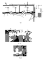
Figure 1 schematically shows the application of the method according to the invention to a fuel tank provided with several devices. -
Figure 2 shows a pipe located inside a fuel tank protected according to the method of the present invention. -
Figure 3 shows a support located in the wall of a fuel tank protected according to the method of the present invention. - According to
Figure 1 , a fuel tank 11 manufactured with a material with low electrical conductivity, adevice 13 consisting of a fuel pipe and a device 15 consisting of a piece of equipment with a metal casing, can be observed. The group ofdevices 13, 15 represents the metal installations located inside the tank 11 that are necessary for handing fuel. - According to the method object of the present invention, insulating
members 21 are included, which can be made from a plastic material, at the points in which thedevices 13 and 15 are fixed/attached to the tank 11 to insulate saiddevices 13 and 15 from the tank 11. -
Figure 3 shows a specific example of aninsulating member 21 at a fixing point of a tank 11. - For its part, several
insulating inserts 23 of a non-conducting material, for instance plastic, are included in thepipe 13, definingparts 31, 33 and 35 therein insulated from one another. -
Figure 2 shows an example of aninsulating insert 23 in thepipe 13 located between two connections with asubstructure 25 with a reference potential. - Finally, connections for
parts 31, 33 and 35 of thepipe 13 and the device 15, which can be considered a part insulated from the remaining devices, with asub-structure 25 with a reference potential ("0 volts"), are provided. Thedevices 13 and 15, which can be submerged in the fuel, can accumulate charge up to certain levels as a result of the generation of a static charge after the tank 11 receives an electrical discharge, but said connections prevent the occurrence of electric arcs and prevent the increase of said charge up to certain admissible energy levels (200 micro-Jules) by draining the static charge and prevent its accumulation in the system components. - The basis of the method object of the present invention is to prevent the current Ce circulating through the outer walls of the fuel tank 11 as a result of an electrical discharge caused, for example, by a lightning strike, from being shunted to the inner areas where the
devices 13 and 15 are located. - Since the entire installation, made up of the
devices 13 and 15 insulated from the main structure of the tank 11, is internal the only pathway for the external current Ce is the one that provides the points of connection to thesub-structure 25 with a reference potential (metallic). - The inductance and low section associated to said electrical points of connection and the presence of the
insulating inserts 23 in thefuel pipe 13 make the external current Ce circulate towards the inside through shunts Cs at very low levels. Therefore the only current to which the metallic members of the system inside the tank are subjected is the one corresponding to the induction effect Ci. - On the other hand the
insulating inserts 23 in thefuel pipes 13 or any other linear device prevent the possibility that the current Ci forms closed circuits where the circulation of high density current occurs repeatedly. - The insulating
inserts 23 must maintain certain length dimensions to prevent electric arcs. In particular, the range of applicable distances that have been tested and applied in aircraft fuel tanks designed and manufactured by Airbus is comprised between 25-80 mm. - The insulating
inserts 23 must be manufactured with an insulating material that is capable of providing electrical isolation exceeding 100 mega-Ohms for the purpose of withstanding the possible differences of potential that may occur due to a severe electrical discharge. - The determination of the points where the
insulating inserts 23 must be located requires a detailed study of the resistances existing in the system as well as the study of the induced current levels on each area of the system in the most critical case of external electrical discharge. Nevertheless it is thought to be a general rule that an electrical resistance of less than 10 milli-Ohms must exist between any metallic section of the sub-structure 25 (reference potential) and eachpart 31, 33, 35 of thepipe 13 or any other linear device located inside the fuel tank 11 arranged between twoinsulating inserts 23. - It must be pointed out that most of the essence of the technique proposed in this application is based on these
insulating inserts 23 given that they prevent that there are high electric currents circulating through the metallic parts belonging to the internal systems of the fuel tank. On certain occasions these insulating components must have a very novel design/material/geometry since they must be located in very small areas or in very short pipe sections. - The effectiveness of the solution applied for is supported by several tests performed by the applicant company in relation to the fuel system located in the horizontal stabilizer of different airplane models.
- Modifications comprised within the scope defined by the following claims may be introduced in the preferred embodiment described above.
Claims (4)
- A method of protecting a group of metal devices (13, 15) installed inside a fuel tank (11), manufactured either completely or partially with composites, against electrical discharges, characterized in that:a) an insulating member (21) is included at the points where the metal devices (13, 15) are fixed/attached to the fuel tank (11) to assure the electrical insulation of said metal devices (13, 15) with respect to the fuel tank (11);b) insulating inserts (23) are included in the linear metal devices (13) such that they are subdivided into parts (31, 33, 35) insulated from one another;c) a connection with a metal sub-structure (25) with a very low resistance is provided in each one of the parts (31, 33, 35) insulated from one another in the group of metal devices (13, 15).
- A method of protecting a group of metal devices (13, 15) arranged inside a fuel tank (11) according to claim 1, characterized in that the insulating inserts (23) provide an electrical resistance exceeding 100 mega-Ohms.
- - A method of protecting a group of metal devices (13, 15) arranged inside a fuel tank (11) according to claim 2, characterized in that the division of the linear devices (13) into parts (31, 33, 35) is carried out such that there is an electrical resistance of less than 10 milli-Ohms between each one of them and the metal sub-structure (25).
- - A method of protecting a group of metal devices (13, 15) arranged inside a fuel tank (11) according to any of the previous claims, characterized in that said fuel tank is located in an aircraft wing and/or stabilizer.
Applications Claiming Priority (1)
| Application Number | Priority Date | Filing Date | Title |
|---|---|---|---|
| PCT/ES2005/070133 WO2007039650A1 (en) | 2005-09-29 | 2005-09-29 | Method of protecting fuel tanks that are made from composite materials against electric discharges |
Publications (2)
| Publication Number | Publication Date |
|---|---|
| EP1939088A1 true EP1939088A1 (en) | 2008-07-02 |
| EP1939088A4 EP1939088A4 (en) | 2012-04-18 |
Family
ID=37905958
Family Applications (1)
| Application Number | Title | Priority Date | Filing Date |
|---|---|---|---|
| EP05799717A Withdrawn EP1939088A4 (en) | 2005-09-29 | 2005-09-29 | Method of protecting fuel tanks that are made from composite materials against electric discharges |
Country Status (7)
| Country | Link |
|---|---|
| US (1) | US20080013246A1 (en) |
| EP (1) | EP1939088A4 (en) |
| JP (1) | JP4995823B2 (en) |
| CN (1) | CN101312879B (en) |
| BR (1) | BRPI0520590A2 (en) |
| CA (1) | CA2624511A1 (en) |
| WO (1) | WO2007039650A1 (en) |
Cited By (2)
| Publication number | Priority date | Publication date | Assignee | Title |
|---|---|---|---|---|
| WO2011007100A3 (en) * | 2009-07-16 | 2012-04-05 | Airbus Operations (S.A.S) | Device for protecting piping from lightning |
| RU2493085C2 (en) * | 2009-03-30 | 2013-09-20 | Mitsubishi Heavy Industries, Ltd. | Tank of composite, wing and method of making said tank |
Families Citing this family (12)
| Publication number | Priority date | Publication date | Assignee | Title |
|---|---|---|---|---|
| BRPI0520793A2 (en) | 2005-12-23 | 2009-05-26 | Airbus Espana Sl | current isolation device for fuel systems |
| EP2034228A4 (en) | 2006-06-22 | 2011-03-30 | Airbus Espana Sl | Current-insulating system for fluid systems |
| GB2473226A (en) * | 2009-09-04 | 2011-03-09 | Hexcel Composites Ltd | Composite materials |
| US8124182B2 (en) * | 2007-06-15 | 2012-02-28 | The Boeing Company | Application of insulating coating |
| US8003014B2 (en) * | 2008-07-02 | 2011-08-23 | Eaton Corporation | Dielectric isolators |
| US9136036B2 (en) * | 2008-07-02 | 2015-09-15 | Miller Waster Mills | Injection moldable, thermoplastic composite materials |
| US8956556B2 (en) * | 2008-07-02 | 2015-02-17 | Eaton Corporation | Dielectric isolators |
| JP5210925B2 (en) * | 2009-02-27 | 2013-06-12 | 三菱重工業株式会社 | Fuel tank ignition prevention structure |
| JP5101554B2 (en) | 2009-03-30 | 2012-12-19 | 三菱重工業株式会社 | Aircraft fuel tank |
| CA2903971A1 (en) | 2013-03-06 | 2014-09-12 | Bombardier Inc. | Tank wall connector system |
| US11530633B2 (en) * | 2019-12-05 | 2022-12-20 | Rolls-Royce Corporation | Efficient grounding of electrical connection with challenging bonding path |
| DE102021105609A1 (en) * | 2021-03-09 | 2022-09-15 | Airbus Operations Gmbh | Flow body for an aircraft with an integrated gas tank |
Family Cites Families (13)
| Publication number | Priority date | Publication date | Assignee | Title |
|---|---|---|---|---|
| US4479163A (en) * | 1982-09-30 | 1984-10-23 | The Boeing Company | Integral lightning protection system for composite aircraft skins |
| US4630789A (en) * | 1983-09-23 | 1986-12-23 | The Boeing Company | Dielectric isolated fuel and hydraulic tubes |
| US4654747A (en) * | 1985-09-30 | 1987-03-31 | The Boeing Company | Dielectric isolation of metallic conduits |
| FR2609546B1 (en) * | 1987-01-08 | 1991-01-04 | Aerospatiale | METHOD AND SYSTEM FOR DETERMINING THE LONGITUDINAL POSITION OF THE CENTER OF GRAVITY OF AN AIRCRAFT PROVIDED WITH AN ADJUSTABLE HORIZONTAL FENDER |
| FR2617568B1 (en) * | 1987-07-02 | 1989-10-20 | Aerospatiale | TUBE FOR THE CIRCULATION OF A FLAMMABLE FLUID, AND PIPING MADE FROM SUCH TUBES |
| ES2006356A6 (en) * | 1988-03-07 | 1989-04-16 | Const Aeronauticas Sa | A system of protection against electrical shock, especially rays, of structural components of aircraft, particularly deposits or fuel tanks manufactured from composite materials. (Machine-translation by Google Translate, not legally binding) |
| US4971268A (en) * | 1988-11-23 | 1990-11-20 | The Boeing Company | Dielectric support and wear sleeve |
| CN2178701Y (en) * | 1993-12-29 | 1994-10-05 | 王玉忠 | Anti-explode semi-conductor heating stick |
| JP3517773B2 (en) * | 1998-04-07 | 2004-04-12 | 豊田合成株式会社 | Resin fitting for fuel hose |
| CN2338270Y (en) * | 1998-06-19 | 1999-09-15 | 中国航空工业总公司第六○一研究所 | Lightning protection device of aircraft airspeed head |
| ES2162718A1 (en) * | 1998-07-29 | 2002-01-01 | Const Aeronauticas Sa | Lightning protection system for composite aircraft structures |
| US7001158B2 (en) * | 2003-01-24 | 2006-02-21 | Sturman Industries, Inc. | Digital fluid pump |
| ES2264299B1 (en) * | 2003-06-06 | 2007-11-16 | Airbus España S.L. | LIGHTNING PROTECTION SYSTEM FOR FUEL TANKS MANUFACTURED IN POOR ELECTRICAL CONDUCTIVITY MATERIALS. |
-
2005
- 2005-09-29 EP EP05799717A patent/EP1939088A4/en not_active Withdrawn
- 2005-09-29 JP JP2008532811A patent/JP4995823B2/en not_active Expired - Fee Related
- 2005-09-29 CA CA002624511A patent/CA2624511A1/en not_active Abandoned
- 2005-09-29 WO PCT/ES2005/070133 patent/WO2007039650A1/en not_active Ceased
- 2005-09-29 CN CN2005800521296A patent/CN101312879B/en not_active Expired - Fee Related
- 2005-09-29 BR BRPI0520590-5A patent/BRPI0520590A2/en not_active Application Discontinuation
- 2005-11-14 US US11/273,636 patent/US20080013246A1/en not_active Abandoned
Cited By (3)
| Publication number | Priority date | Publication date | Assignee | Title |
|---|---|---|---|---|
| RU2493085C2 (en) * | 2009-03-30 | 2013-09-20 | Mitsubishi Heavy Industries, Ltd. | Tank of composite, wing and method of making said tank |
| WO2011007100A3 (en) * | 2009-07-16 | 2012-04-05 | Airbus Operations (S.A.S) | Device for protecting piping from lightning |
| US8947846B2 (en) | 2009-07-16 | 2015-02-03 | Airbus Operations S.A.S. | Device for protecting piping from lightning |
Also Published As
| Publication number | Publication date |
|---|---|
| BRPI0520590A2 (en) | 2009-05-19 |
| WO2007039650A1 (en) | 2007-04-12 |
| CA2624511A1 (en) | 2007-04-12 |
| JP4995823B2 (en) | 2012-08-08 |
| CN101312879B (en) | 2010-05-12 |
| US20080013246A1 (en) | 2008-01-17 |
| JP2009509848A (en) | 2009-03-12 |
| EP1939088A4 (en) | 2012-04-18 |
| CN101312879A (en) | 2008-11-26 |
Similar Documents
| Publication | Publication Date | Title |
|---|---|---|
| US20080013246A1 (en) | Method of protecting fuel tanks manufactured with composites against electrical discharges | |
| US9885434B2 (en) | Bulkhead fitting assembly and method of making | |
| US7686344B2 (en) | Current insulation system for fluid systems | |
| CN102712370B (en) | The lightning protection of pipeline | |
| US20150091293A1 (en) | Apparatus for preventing spark propagation | |
| EP1826120A2 (en) | Method and system for electrical bonding of fuel tank penetrations | |
| US8711540B2 (en) | Device for installing conducting components in structures | |
| EP2791565B1 (en) | Ferrule protected from electrostatic discharge | |
| US7342765B2 (en) | Current insulation device for fuel systems | |
| US20130075150A1 (en) | Bushing for use in providing electromagnetic effects protection | |
| Galván et al. | Protection of oil storage tanks against direct lightning strikes: Self protection scheme or standalone LPS? | |
| RU2374145C1 (en) | Method to protect composite-material fuel tank against electric discharges | |
| RU2406006C2 (en) | System for current isolation for fluid systems | |
| Gieras | Selected Technical Aspects of Tu-154M Smolensk Air Crash on April 10, 2010. | |
| Sikand et al. | Fuel tank safety on airplanes | |
| Bouquegneau | Lightning protection of oil and gas industrial plants | |
| Yang et al. | Overview of electrical wiring installation inside fuel tanks of civil aircraft | |
| Sanders | NFPA 780 standard for the installation of lightning protection systems 2011 edition | |
| Priya Surya | Requirements of Grounding, Bonding, and Lightning Protection System for Aircraft System | |
| Standard | Lightning Strike Protection Requirements for Service Aircraft | |
| Guthrie et al. | Lightning related ignition mechanism and associated protection techniques for storage applications | |
| Lorenz | AN INVESTIGATION OF LIGHTNING DAMAGE TO NONMETALLIC COMPOSITE AIRCRAFT MATERIALS AND ASSOCIATED PROTECTIVE SYSTEMS. | |
| Harris | Conference on Lightning and Static Electricity, Held at Culham Laboratory, Abingdon, England on 14-18 April 1975 |
Legal Events
| Date | Code | Title | Description |
|---|---|---|---|
| PUAI | Public reference made under article 153(3) epc to a published international application that has entered the european phase |
Free format text: ORIGINAL CODE: 0009012 |
|
| 17P | Request for examination filed |
Effective date: 20080424 |
|
| AK | Designated contracting states |
Kind code of ref document: A1 Designated state(s): AT BE BG CH CY CZ DE DK EE ES FI FR GB GR HU IE IS IT LI LT LU LV MC NL PL PT RO SE SI SK TR |
|
| RAP1 | Party data changed (applicant data changed or rights of an application transferred) |
Owner name: AIRBUS OPERATIONS S.L. |
|
| RIC1 | Information provided on ipc code assigned before grant |
Ipc: F16L 25/02 20060101ALI20120213BHEP Ipc: B65D 45/02 20060101ALI20120213BHEP Ipc: B64D 37/32 20060101AFI20120213BHEP |
|
| A4 | Supplementary search report drawn up and despatched |
Effective date: 20120319 |
|
| RIC1 | Information provided on ipc code assigned before grant |
Ipc: F16L 25/02 20060101ALI20120312BHEP Ipc: B64D 37/32 20060101AFI20120312BHEP Ipc: B65D 45/02 20060101ALI20120312BHEP |
|
| DAX | Request for extension of the european patent (deleted) | ||
| 17Q | First examination report despatched |
Effective date: 20130103 |
|
| STAA | Information on the status of an ep patent application or granted ep patent |
Free format text: STATUS: THE APPLICATION IS DEEMED TO BE WITHDRAWN |
|
| 18D | Application deemed to be withdrawn |
Effective date: 20130514 |