EP1939087A1 - Rotorcraft rotor improvement equipped with inter-blade shock absorbers - Google Patents
Rotorcraft rotor improvement equipped with inter-blade shock absorbers Download PDFInfo
- Publication number
- EP1939087A1 EP1939087A1 EP07023730A EP07023730A EP1939087A1 EP 1939087 A1 EP1939087 A1 EP 1939087A1 EP 07023730 A EP07023730 A EP 07023730A EP 07023730 A EP07023730 A EP 07023730A EP 1939087 A1 EP1939087 A1 EP 1939087A1
- Authority
- EP
- European Patent Office
- Prior art keywords
- blade
- axis
- rotor
- drag
- joints
- Prior art date
- Legal status (The legal status is an assumption and is not a legal conclusion. Google has not performed a legal analysis and makes no representation as to the accuracy of the status listed.)
- Granted
Links
Images


Classifications
-
- B—PERFORMING OPERATIONS; TRANSPORTING
- B64—AIRCRAFT; AVIATION; COSMONAUTICS
- B64C—AEROPLANES; HELICOPTERS
- B64C27/00—Rotorcraft; Rotors peculiar thereto
- B64C27/51—Damping of blade movements
-
- B—PERFORMING OPERATIONS; TRANSPORTING
- B64—AIRCRAFT; AVIATION; COSMONAUTICS
- B64C—AEROPLANES; HELICOPTERS
- B64C27/00—Rotorcraft; Rotors peculiar thereto
- B64C27/32—Rotors
- B64C27/35—Rotors having elastomeric joints
-
- Y—GENERAL TAGGING OF NEW TECHNOLOGICAL DEVELOPMENTS; GENERAL TAGGING OF CROSS-SECTIONAL TECHNOLOGIES SPANNING OVER SEVERAL SECTIONS OF THE IPC; TECHNICAL SUBJECTS COVERED BY FORMER USPC CROSS-REFERENCE ART COLLECTIONS [XRACs] AND DIGESTS
- Y10—TECHNICAL SUBJECTS COVERED BY FORMER USPC
- Y10S—TECHNICAL SUBJECTS COVERED BY FORMER USPC CROSS-REFERENCE ART COLLECTIONS [XRACs] AND DIGESTS
- Y10S416/00—Fluid reaction surfaces, i.e. impellers
- Y10S416/50—Vibration damping features
Definitions
- the present invention relates to an improvement to rotors of rotorcraft equipped with interpale dampers.
- the technical field of the invention is that of the manufacture including helicopters.
- the invention relates to rotorcraft rotors comprising a hub driven in rotation along an axis of rotation by an output shaft of a power transmission gearbox or drive shaft, and at least three blades fixed to the hub by the intermediate of appropriate joints, in particular via a laminated spherical abutment dedicated to each blade, and interpale dampers each connecting two adjacent blades.
- the rotor thus formed is a rigid rotor.
- the distribution of aerodynamic forces along a blade generates a bending moment distribution whose value is very important at the foot of the blade.
- the so-called "advancing" blade carries more than the so-called “receding” blade due to the unevenness of the air speeds as will be specified elsewhere.
- the resultant aerodynamic forces exerted on a blade do not have the same value at each azimuth or the same point of application: the moment of embedding at the foot of the blade is thus high and variable, which generates alternating stresses leading to a phenomenon of detrimental fatigue of the materials.
- the resultant aerodynamic forces of all the blades are no longer carried by the axis rotor which causes the creation of a moment of rolling, increasing with the speed which can make the balance of forces in translation flight difficult.
- the plane of rotation of the blades may be different from the plane perpendicular to the drive shaft.
- it is necessary to articulate each blade in drag because the end of each blade is at a variable distance from the rotor shaft, as explained more specifically later about the Coriolis forces. Otherwise, it would necessarily appear inertial forces generating alternating bending moments of each blade in its plane.
- Such articulation of drag is done by articulating a blade about a drag axis substantially parallel to the rotor axis, and therefore substantially perpendicular to the drag forces.
- the three rotations II-III and IV above can be performed by a single member such as a laminated spherical abutment, as is the case for the SUPER PUMA MKII or NH90 helicopters of the Applicant where a such organ ensures the mobility of the blade beat, drag and step.
- the oscillations of each blade around its drag axis can unstably couple with the motions or modes of elastic deformations of the cell, in particular the oscillations of the helicopter landed on its landing gear: this is the origin of the phenomenon, called "ground resonance", which can be dangerous for the device when the natural frequency of the oscillations of the blades around their axis of drag is close to one of the natural frequencies of the oscillations of the apparatus around his landers.
- the remedies for this phenomenon consist in introducing on the drag axes damping by a device of the viscous or dry damping type, in particular, or a rigidity with the aid of third-party cables associated or not with dampers as on the helicopter ALOUETTE of the plaintiff.
- dampers comprise resilient return means with stiffness and damping determined, to combat the resonance phenomena, in particular ground resonance and also kinematic chain resonance, which may appear especially on helicopters.
- the blades of a drag rotor are spaced from their equilibrium position and can be unevenly distributed in the circumferential direction, and create an unbalance by displacement of the center of gravity of the rotor out of the axis of rotation of the latter.
- the blades spaced apart from their equilibrium position oscillate around this position at a frequency ⁇ ⁇ , which is the natural frequency of the blades in drag, also called first drag mode or clean drag mode.
- ⁇ is the rotational frequency of the rotor, it is known that the fuselage of the helicopter is thus excited at frequencies
- the fuselage of the helicopter constitutes a mass system suspended above the ground by a spring and a shock absorber at each landing gear.
- the fuselage resting on its landing gear therefore has its own modes of vibration in roll and pitch.
- ground resonance To avoid instability, it is known to seek first to avoid the crossing of these frequencies, and, if this crossing can not be avoided, it is necessary to sufficiently dampen the fuselage on its landing gear and the rotor blades. principal in their drag movement.
- the stiffness of the drag dampers of the blades of a main rotor must be chosen so that the frequency own blades in drag either out of a possible ground resonance zone, while simultaneously having a sufficient damping, because, during the passage of the rotational speed of the rotor at the critical speed, when climbing as on the descent in regime, the blades must be sufficiently damped to avoid a resonance input.
- the drag dampers with determined elastic stiffness return means are also called frequency adapters,
- the stiffness of the damper introduces an equivalent angular stiffness, opposing angular deflections of the blade relative to the hub about its drag axis. It is thus possible to increase the self-mode frequency of the drag blades to move its frequency away from the two aforementioned resonance phenomena.
- the equivalent angular stiffness is proportional to the square of the lever arm between the damper and the drag axis of the blade, that is to say the distance separating the axis of drag from the axis passing through the centers of the blade.
- the interpal implantation of a damper makes it possible to increase the lever arms between the dampers and the drag axes of the blades, but also to involve two dampers per blade to avoid ground resonance.
- the stiffness of each damper can be limited accordingly, and a benefit that arises is a lower level of static force introduced by mounting each damper interpale adapter. This implantation is therefore very favorable to fight the ground resonance.
- the invention relates in particular to an improvement to rotors of rotorcraft described in the patents FR 2,630,703 and US 4,915,585 relating to a rotor head comprising on the one hand blades connected to the drive hub by appropriate knuckles in vertical beat, drag and pitch, in particular laminated spherical abutments as previously presented and on the other hand interpalescent tie rods elastic return with incorporated damping, as described above.
- each blade is fixed to the hub by a sleeve whose ends are in the form of clevis with two branches spaced and in mutual relation.
- Each interpale damper is attached to two adjacent blades by two respective ball joints.
- Each sleeve is fixed to the hub of the rotor by a laminated spherical abutment and receives two respective fixing brackets of two dampers.
- These ball joints are centered on the pitch axis of the blade or located in the immediate vicinity of this axis, and are also fixed between the two branches of the sleeve, outside the articulation center in steps, flapping, and drag of the blade relative to the hub, corresponding to a laminated spherical abutment.
- the invention applies to a rotorcraft rotor having a hub driven in rotation along an axis of rotation, at least three blades fixed to the hub each by means of knuckle, drag and pitch joints, in particular constituted by a laminated spherical stop, each blade having a pitch variation axis, a leading edge and a trailing edge, the rotor further comprising interpale drag dampers each connected to two adjacent blades respectively via the less than two spherical joints (or kneecaps).
- the axes of vertical flapping, drag and pitch are by definition concurrent in the center of said abutment.
- the two joints respectively connecting the respective blade to two interpale dampers are disposed on either side of the pitch variation axis of the blade, one at less of these two joints being offset above the plane P containing the axes of variation of pitch and vertical beat of said blade, that is to say in the positive direction of an axis orthogonal to the plane P, this axis being oriented positively towards the top of the rotorcraft.
- the invention makes it possible to significantly reduce the level of interpalesional oscillations at the rotation frequency of the rotor, which makes it possible to increase the lifetime of the inter-damper and its damping performance.
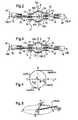
- FIG. 1 On the figure 1 partially shown a quadripal rotor head 1 of a rotorcraft whose rigid hub 2 is integral in rotation with a rotor mast (not shown) about the axis of rotation 100, the speed of rotation of the hub 2 being designated by ⁇ .
- the rotor mast attached to a main gearbox (BTP) of power, transmits rotorcraft lift to the rotorcraft structure and supports the blades 4 which convert the mechanical energy of the engines into aerodynamic forces.
- BTP main gearbox
- the hub 2 serves as a point of attachment to each of the blades 4 by means of a sleeve 5 comprising an internal radial clevis 6 equipped with a laminated spherical joint 7 (or spherical abutment) for connection to the hub 2 and an outer radial clevis 8 or retaining fitting of the corresponding blade 4.
- each laminated spherical joint 7 allows the articulation of each corresponding blade 4 in vertical flapping around the vertical flap axis 102, in drag as well as in pitch variation around the pitch variation axis 101 of the blade.
- the variation of pitch is done by action of the pitch control 9 causing a rotation of the corresponding blade 4 around the axis of pitch variation 101.
- spherical abutment may possibly be made by separate means such as axes of rotation, for example.
- the pitch control 9 of each blade 4 is located on the side of the trailing edge BF of each blade, the leading edge of each blade being designated BA.
- the rotor 1 comprises interpalescent elastic return rods 15 or interpale drag dampers (or frequency adapters), each interpale drag damper being connected to two spherical joints (or ball joints) 16 mounted in clevis at each end of a shock absorber.
- these two joints 16 are on either side of the pitch variation axis 101 of each blade 4, at least one of these hinges 16 being shifted above the plane P containing the axes of variation of step 101 and the vertical beat axis 102 that is to say in the positive direction of the orthogonal axis 103, orthogonal to the plane P, this orthogonal axis 103 being oriented positively towards the top of the rotorcraft.
- these joints 16 can be arranged on each sleeve 15 according to the representations of the Figures 2 and 3 .
- hinges 16 on another support such as a blade, for example, or on a sleeve as described by the patents.
- EP0448685 and EP0085129 especially.
- each hinge 16 is taken up, for example, by a double clevis-shaped fitting 13, 14 disposed on a sleeve 5 (or any other support), so that such a sleeve comprises, with respect to the blade 4 corresponding a first fitting 11 located on the side of the leading edge BA of said blade and a second fitting 12 located on the side of the trailing edge BF of the same blade.
- the hinge 16 (and consequently the bracket 11) located towards the leading edge BA of a blade 4 is lower, with respect to the positive orientation of the blade. orthogonal axis 103, that the hinge 16 (and consequently the fitting 12 associated) located towards the trailing edge BF of said blade 4.
- the figure 2 schematically represents a sleeve 5 in cross section along the axis II-II of the figure 1 .
- the sleeve 5 driving a blade 4 is linked to the left of the figure 2 a first interpale damper 15 by the first fitting 11, located on the leading edge side of the corresponding blade 4 via a hinge 16 whose central axis 17 is retained by the double yoke 13, 14.
- the sleeve 5 is also linked to the right of the figure 2 to a second damper 5 by means similar to those used for fixing the first damper via a second fitting 12 located on the trailing edge side of the blade 4 in question.
- the fitting 12 is disposed above the plane P formed by the axis of variation of the pitch 101 and the vertical axis of flapping 102, that is to say in the positive direction of the axis orthogonal 103, towards the top of the rotorcraft.
- the axes of rotation 100 and orthogonal 103 are parallel when the plane P is orthogonal to the axis of rotation 100 of the hub.
- the two hinges 16 respectively connecting the blade 4 in question to two "adjacent" interpale drag dampers are disposed on either side of the axis of variation of the pitch 101, the hinge 16 located on the edge side. LF leakage of the blade 4 being shifted above the plane P containing the axes of pitch variation 101 and vertical beat 102.
- the virtual axis 104 connecting the two centers of the respective attachment joints 16 of two spacer dampers 15 and adjacent to a blade 4 is offset in elevation, with respect to the pitch variation axis 101, namely positively with respect to the axis of rotation 100.
- this virtual axis 104 has a shift C1 so as never to cut the pitch variation axis 101.
- the hinge 16 relative to the fitting 11 (leading edge side BA of the blade 4) is lower than the hinge 16 relative to the fitting 12 (trailing edge side BF of the blade 4).
- two joints 16 connecting the blade 4 to two adjacent interphalic drag dampers 15 can also be shifted along an axis parallel to the orthogonal axis 103. This is the case represented on FIG. figure 3 where the two joints 16 are above the plane formed by the pitch variation axis 101 and the vertical flap axis 102. This also results in an offset of the fittings 11 and 12 towards the positive direction of the orthogonal axis 103.
- joints 16 can be installed on any type of sleeve or on any suitable support (sleeve, .).
- a rotorcraft moving in translation flight at a speed u is considered and it is agreed that the positions of the main rotor blades are defined by their azimuth ⁇ , generally determined from the rear position, the rotational speed of the rotor being designated by ⁇ .
- the tangential velocity U of a blade element located at a distance R from the center O of the rotor, is composed with the translation speed ⁇ .
- the resulting velocity V then admits a tangential component U R which is the relative speed of the blade with respect to the air.
- the speed U of a blade element equal to ⁇ R in D becomes ⁇ r r since the blade considered is provided with a drag joint.
- the blade element tends to maintain its initial speed U inertia during the change of trajectory.
- the speed ⁇ r is greater than ⁇ : the blade oscillates forward. The bending moment that would be created in the plane of the blade is canceled due to the introduction of the drag joint.
- the blade is solicited by Coriolis forces that make it oscillate in the plane orthogonal to the axis of drag around a mean position.
- the Coriolis forces result from the superimposition of the relative movement due to the beat and the drive movement due to the own rotation of the blades.
- the rotation speed ⁇ characterizes the drive movement of a blade and the speed ⁇ r lifting of the blade corresponds to the relative movement.
- the reduction of these charges is equivalent to reducing the large deflections imposed on the dampers under the effect of the periodic excitation of the rotor.
- the search for a lowering of the deflections imposed on a damper aims to improve the performance of the dampers, particularly in terms of service life, and subsequently a reduction in mechanical stresses of the various elements of a rotorcraft rotor.
- the C2 configuration is the most favorable because it allows a reduction of dynamic elongations by a factor of order 2.
- This offset in the positive direction of the axis 103 is substantially equivalent to an additional conicity of the order of 0.17 rd, or nearly ten degrees, the joints 16 being 0.345m from the laminated spherical abutment 7.
- the abscissa and ordinate axes also correspond respectively to the azimuth of a blade and to the overall displacements of the damper.
- each blade describes a cone whose virtual axis is at an angle to 1 with the drive axis, or axis of the hub or rotor shaft (normal to the drive plane), the latter corresponding to the carrier of the vector rotation ⁇ .
- the plane of the rotor, described by the end of the blades is also inclined at the angle a 1 relative to the drive plane.
- the angle a 1 is relative to a longitudinal tilting of the rotor, while a lateral tilting is indicated by an angle b 1 .
- the figure 12 shows that the ends of the blades do not rotate in their plane of a uniform movement so that in equal times corresponding to a quarter turn of the rotor shaft, they describe arcs AB, BC, CD and DA which are as much more unequal as the quantities at 0 and at 1 are larger. This observation is also explained by the fact that the blades are at a variable distance from the rotor shaft.
- FIG 12 shows that a blade in position C corresponds to a maximum flapping angle with respect to ⁇ whereas a blade in position A is relative to a minimum flap angle.
- a blade is rising from A to B and C, then down.
- an in-flight experimentation campaign with a SUPER PUMA MKII helicopter of the Applicant demonstrates that a cross position (differential) of the joints 16 is interesting for this type of aircraft.
- the application was made with a configuration C4 relating to a shift d of the articulation 16 to the trailing edge of a blade of 0.035m above the plane P, the articulation 16 at the leading edge of the same blade being offset by -0.005m that is to say towards the bottom of the plane P.
- the two articulations 16 of said blade are well offset along the axis 103, orthogonal to the plane P, and the articulation 16 on the side of the trailing edge of the blade is well above the plane P.
- the initial configuration, without offset of the two joints 16 is denoted CO.
- joints 16 such that the hinge 16 at the trailing edge is at 0.075m, above the plane P (C5 configuration), that relative to the edge of attack being at 0.005m below this plane.
- angle A1 relative to the configurations C4 and C5 is respectively ten degrees and twenty two degrees.
- the optimum range for the angle A1 is substantially between seven and twenty-two degrees, taking into account the specific research carried out on the applicant's EC155 helicopter. Under these conditions, it also results in the values of the angle B1 presented above.
Abstract
Description
La présente invention est relative à une amélioration aux rotors de giravions équipés d'amortisseurs interpales.The present invention relates to an improvement to rotors of rotorcraft equipped with interpale dampers.
Le domaine technique de l'invention est celui de la fabrication notamment d'hélicoptères.The technical field of the invention is that of the manufacture including helicopters.
L'invention concerne les rotors de giravions comportant un moyeu entraîné en rotation selon un axe de rotation par un arbre de sortie d'une boite de transmission de puissance ou arbre d'entraînement, ainsi qu'au moins trois pales fixées au moyeu par l'intermédiaire d'articulations appropriées, en particulier par l'intermédiaire d'une butée sphérique lamifiée dédiée à chaque pale, et des amortisseurs interpales reliant chacun deux pales adjacentes.The invention relates to rotorcraft rotors comprising a hub driven in rotation along an axis of rotation by an output shaft of a power transmission gearbox or drive shaft, and at least three blades fixed to the hub by the intermediate of appropriate joints, in particular via a laminated spherical abutment dedicated to each blade, and interpale dampers each connecting two adjacent blades.
En effet, il est rappelé que dans l'hypothèse de l'encastrement de chaque pale sur un moyeu, le rotor ainsi constitué est un rotor rigide. En vol stationnaire, la répartition des efforts aérodynamiques le long d'une pale engendre une répartition de moment de flexion dont la valeur est très importante au pied de la pale. En vol de translation, la pale dite « avançante » porte plus que la pale dite « reculante » du fait de l'inégalité des vitesses de l'air comme cela sera précisé par ailleurs.Indeed, it is recalled that in the event of embedding each blade on a hub, the rotor thus formed is a rigid rotor. In hovering, the distribution of aerodynamic forces along a blade generates a bending moment distribution whose value is very important at the foot of the blade. In translation flight, the so-called "advancing" blade carries more than the so-called "receding" blade due to the unevenness of the air speeds as will be specified elsewhere.
Par conséquent, la résultante des forces aérodynamiques exercées sur une pale n'a donc pas la même valeur en chaque azimut, ni le même point d'application : le moment d'encastrement au pied de la pale est ainsi élevé et variable, ce qui génère des contraintes alternées entraînant un phénomène de fatigue préjudiciable des matériaux. De plus, la résultante des forces aérodynamiques de toutes les pales n'est plus portée par l'axe rotor ce qui entraîne la création d'un moment de roulis, croissant avec la vitesse qui peut rendre difficile l'équilibre des forces en vol de translation.Consequently, the resultant aerodynamic forces exerted on a blade do not have the same value at each azimuth or the same point of application: the moment of embedding at the foot of the blade is thus high and variable, which generates alternating stresses leading to a phenomenon of detrimental fatigue of the materials. In addition, the resultant aerodynamic forces of all the blades are no longer carried by the axis rotor which causes the creation of a moment of rolling, increasing with the speed which can make the balance of forces in translation flight difficult.
Afin de remédier à ces inconvénients, il est connu d'articuler les pales sur le moyeu autour d'un axe perpendiculaire à l'arbre d'entraînement et désigné axe de battement vertical auquel correspond une articulation de battement vertical capable de reprendre une force d'orientation quelconque mais ne peut, en aucun cas, reprendre un moment. Par conséquent, si une pale est articulée sur le moyeu, le moment sera nul à l'attache. Pour satisfaire l'équilibre d'une pale, les efforts centrifuges maintiennent la pale après une certaine levée de celle-ci, laissant apparaître une conicité a0.To overcome these drawbacks, it is known to articulate the blades on the hub about an axis perpendicular to the drive shaft and designated vertical flap axis which corresponds to a vertical flap hinge capable of resuming a force of any orientation but can not, in any case, take a moment. Therefore, if a blade is hinged to the hub, the moment will be zero at the fastener. To satisfy the equilibrium of a blade, the centrifugal forces maintain the blade after some lifting thereof, leaving a taper at 0 .
Dans ces conditions, il n'y a plus de moment de roulis important en translation d'une part et les pales ne tournent plus dans un plan, mais leurs extrémités extérieures décrivent un cône très ouvert. En pratique, l'axe de battement ne se trouve plus, alors, sur l'axe de rotation mais est décalé d'une distance a1 appelée excentricité.Under these conditions, there is more moment of significant roll in translation on the one hand and the blades no longer rotate in a plane, but their outer ends describe a very open cone. In practice, the beat axis is no longer, then, on the axis of rotation but is shifted by a distance to 1 called eccentricity.
Il convient encore de rappeler qu'il faut, pour assurer la sustentation d'un hélicoptère lors de ses différentes configurations, pouvoir contrôler la sustentation du rotor et la faire varier. C'est ainsi qu'est introduite l'articulation de pas, dont l'axe est sensiblement parallèle à l'envergure de la pale correspondante, Ce nouveau degré de liberté permet de contrôler la portance de la pale par action sur la commande de pas général et aussi de faire varier le pas cycliquement, permettant ainsi le contrôle du plan de rotation des pales qui décrivent alors un cône dont l'axe virtuel ne coïncide plus avec l'axe d'entraînement : la résultante des forces appliquées au moyeu change de direction en même temps que le plan du rotor. De ce fait, il en résulte des moments autour du centre de gravité de l'hélicoptère, ce qui permet son pilotage.It should also be remembered that it is necessary, to ensure the lift of a helicopter in its various configurations, to control the lift of the rotor and vary it. This is how the pitch articulation is introduced, the axis of which is substantially parallel to the span of the corresponding blade. This new degree of freedom makes it possible to control the lift of the blade by acting on the pitch control. general and also to vary the pitch cyclically, thus allowing control of the plane of rotation of the blades which then describe a cone whose virtual axis no longer coincides with the drive axis: the resultant forces applied to the hub changes from direction at the same time as the plane of the rotor. As a result, there are moments around the center of gravity of the helicopter, which allows its piloting.
Comme indiqué précédemment, le plan de rotation des pales peut être différent du plan perpendiculaire à l'arbre d'entraînement. Dans ces conditions, il est nécessaire d'articuler chaque pale en traînée car l'extrémité de chaque pale est à une distance variable de l'arbre rotor, comme expliqué plus précisément par la suite à propos des forces de Coriolis. Sinon, il apparaîtrait nécessairement des forces d'inertie, génératrices de moments de flexion alternée de chaque pale dans son plan. Une telle articulation de traînée se fait en articulant une pale autour d'un axe de traînée sensiblement parallèle à l'axe rotor, et par suite sensiblement perpendiculaire aux efforts de traînée. Pour qu'une telle pale puisse être entraînée à partir de l'arbre d'entraînement, il faut bien sûr que l'articulation de traînée soit suffisamment éloignée de l'axe rotor pour que le moment dû aux forces centrifuges équilibre le moment dû aux forces de traînée et d'inertie, ce qui exige un déport de l'axe de traînée ou excentrement e, et ceci sans que l'angle δ dit de « traînée », soit trop important.As indicated above, the plane of rotation of the blades may be different from the plane perpendicular to the drive shaft. In these conditions, it is necessary to articulate each blade in drag because the end of each blade is at a variable distance from the rotor shaft, as explained more specifically later about the Coriolis forces. Otherwise, it would necessarily appear inertial forces generating alternating bending moments of each blade in its plane. Such articulation of drag is done by articulating a blade about a drag axis substantially parallel to the rotor axis, and therefore substantially perpendicular to the drag forces. For such a blade to be driven from the drive shaft, it is of course necessary that the drag articulation is sufficiently far from the rotor axis that the moment due to centrifugal forces balances the moment due to drag forces and inertia, which requires an offset of the drag axis or eccentricity e, and this without the δ angle called "drag" is too important.
Par conséquent, les pales d'un rotor articulé d'aéronef à voilure tournante, notamment un hélicoptère, peuvent être animées des quatre mouvements suivants :
- I) une rotation autour de l'axe rotor,
- II) une rotation autour de l'axe de battement vertical, grâce à l'articulation de battement vertical,
- III) une rotation autour de l'axe de traînée, encore dit axe de battement horizontal, grâce à l'articulation de battement horizontal, ou articulation de traînée.
- IV) une rotation autour de l'axe de la pale grâce à une articulation de pas (non spécifique des rotors articulés).
- I) a rotation around the rotor axis,
- II) a rotation around the axis of vertical flapping, thanks to the articulation of vertical flapping,
- III) a rotation around the axis of drag, also called horizontal flap axis, thanks to the horizontal flange articulation, or drag articulation.
- IV) a rotation around the axis of the blade thanks to a articulation of pitch (unspecific articulated rotors).
Comme prévu par le brevet
Toutefois, les oscillations de chaque pale autour de son axe de traînée peuvent se coupler de façon instable avec les mouvements ou les modes de déformations élastique de la cellule, en particulier les oscillations de l'hélicoptère posé au sol sur ses atterrisseurs : c'est l'origine du phénomène, désigné « résonance au sol », qui peut être dangereux pour l'appareil lorsque la fréquence propre des oscillations des pales autour de leur axe de traînée est voisine de l'une des fréquences propres des oscillations de l'appareil autour de ses atterrisseurs.However, the oscillations of each blade around its drag axis can unstably couple with the motions or modes of elastic deformations of the cell, in particular the oscillations of the helicopter landed on its landing gear: this is the origin of the phenomenon, called "ground resonance", which can be dangerous for the device when the natural frequency of the oscillations of the blades around their axis of drag is close to one of the natural frequencies of the oscillations of the apparatus around his landers.
Les remèdes à ce phénomène consistent à introduire sur les axes de traînée un amortissement par un dispositif du type amortisseur visqueux ou sec, notamment, ou encore une rigidité à l'aide de câbles de tierçage associés ou non à des amortisseurs comme sur l'hélicoptère ALOUETTE de la demanderesse.The remedies for this phenomenon consist in introducing on the drag axes damping by a device of the viscous or dry damping type, in particular, or a rigidity with the aid of third-party cables associated or not with dampers as on the helicopter ALOUETTE of the plaintiff.
Une fonction analogue à celle des câbles de tierçage est assurée par des liaisons élastiques interpales. En pratique, il s'agit de disposer un amortisseur entre deux pales adjacentes, les fixations d'un tel amortisseur à chacune de deux pales adjacentes étant à égale distance du centre rotor, c'est-à-dire à un rayon identique par rapport à ce centre rotor.A function similar to that of the third-party cables is provided by inter-elastic elastic connections. In practice, it is a question of having a damper between two adjacent blades, the fasteners of such a damper to each of two adjacent blades being equidistant from the rotor center, that is to say to an identical radius with respect to at this rotor center.
Ces amortisseurs comprennent des moyens de rappel élastique à raideur et amortissement déterminés, pour combattre les phénomènes de résonance, en particulier de résonance sol et aussi de résonance de chaîne cinématique qui peuvent apparaître notamment sur les hélicoptères.These dampers comprise resilient return means with stiffness and damping determined, to combat the resonance phenomena, in particular ground resonance and also kinematic chain resonance, which may appear especially on helicopters.
En effet, lors d'une excitation des pales d'un rotor en traînée, les pales sont écartées de leur position d'équilibre et peuvent se répartir inégalement en direction circonférentielle, et créer un balourd par déplacement du centre de gravité du rotor hors de l'axe de rotation de ce dernier. De plus, les pales écartées de leur position d'équilibre oscillent autour de cette position à une fréquence ωδ, qui est la fréquence propre des pales en traînée, appelée également premier mode de traînée ou mode propre de traînée.Indeed, during an excitation of the blades of a drag rotor, the blades are spaced from their equilibrium position and can be unevenly distributed in the circumferential direction, and create an unbalance by displacement of the center of gravity of the rotor out of the axis of rotation of the latter. In addition, the blades spaced apart from their equilibrium position oscillate around this position at a frequency ω δ , which is the natural frequency of the blades in drag, also called first drag mode or clean drag mode.
Si Ω est la fréquence de rotation du rotor, il est connu que le fuselage de l'hélicoptère est ainsi excité aux fréquences |Ω±ωδ|.If Ω is the rotational frequency of the rotor, it is known that the fuselage of the helicopter is thus excited at frequencies | Ω ± ω δ |.
Posé sur le sol par son train d'atterrissage, le fuselage de l'hélicoptère constitue un système à masse suspendue au dessus du sol par un ressort et un amortisseur au niveau de chaque atterrisseur. Le fuselage reposant sur son train d'atterrissage a donc des modes propres de vibration en roulis et en tangage. Il y a risque d'instabilité au sol lorsque la fréquence d'excitation du fuselage sur son train d'atterrissage est voisine de la fréquence propre d'oscillation |Ω+ωδ| ou |Ω-ωδ| ce qui correspond au phénomène dénommé résonance sol. Pour éviter l'instabilité, il est connu de rechercher d'abord à éviter le croisement de ces fréquences, et, si ce croisement ne peut être évité, il faut amortir suffisamment le fuselage sur son train d'atterrissage ainsi que les pales du rotor principal dans leur mouvement de traînée.Placed on the ground by its landing gear, the fuselage of the helicopter constitutes a mass system suspended above the ground by a spring and a shock absorber at each landing gear. The fuselage resting on its landing gear therefore has its own modes of vibration in roll and pitch. There is a risk of instability on the ground when the excitation frequency of the fuselage on its landing gear is close to the natural frequency of oscillation | Ω + ω δ | or | Ω-ω δ | which corresponds to the phenomenon called ground resonance. To avoid instability, it is known to seek first to avoid the crossing of these frequencies, and, if this crossing can not be avoided, it is necessary to sufficiently dampen the fuselage on its landing gear and the rotor blades. principal in their drag movement.
En conséquence, la raideur des amortisseurs de traînée des pales d'un rotor principal doit être choisie pour que la fréquence propre des pales en traînée soit hors d'une zone de résonance sol possible, tout en disposant simultanément d'un amortissement suffisant, car, lors du passage du régime de rotation du rotor au régime critique, lors de la montée comme lors de la descente en régime, les pales doivent être suffisamment amorties pour éviter une entrée en résonance.As a consequence, the stiffness of the drag dampers of the blades of a main rotor must be chosen so that the frequency own blades in drag either out of a possible ground resonance zone, while simultaneously having a sufficient damping, because, during the passage of the rotational speed of the rotor at the critical speed, when climbing as on the descent in regime, the blades must be sufficiently damped to avoid a resonance input.
Pour cette raison, les amortisseurs de traînée à moyens de rappel élastique de raideur déterminée sont également dénommés adaptateurs de fréquence,For this reason, the drag dampers with determined elastic stiffness return means are also called frequency adapters,
De façon générale, la raideur de l'amortisseur introduit une raideur angulaire équivalente, s'opposant aux débattements angulaires de la pale par rapport au moyeu autour de son axe de traînée. On peut ainsi augmenter la fréquence du mode propre des pales en traînée pour éloigner sa fréquence des deux phénomènes de résonance précités.In general, the stiffness of the damper introduces an equivalent angular stiffness, opposing angular deflections of the blade relative to the hub about its drag axis. It is thus possible to increase the self-mode frequency of the drag blades to move its frequency away from the two aforementioned resonance phenomena.
La raideur angulaire équivalente est proportionnelle au carré du bras de levier entre l'amortisseur et l'axe de traînée de la pale, c'est-à-dire la distance séparant l'axe de traînée de l'axe passant par les centres des deux rotules d'articulation de l'amortisseur,The equivalent angular stiffness is proportional to the square of the lever arm between the damper and the drag axis of the blade, that is to say the distance separating the axis of drag from the axis passing through the centers of the blade. two ball joints of the shock absorber,
Par rapport à une implantation plus classique où les amortisseurs sont interposés entre chaque pale et le moyeu du rotor, l'implantation interpale d'un amortisseur permet d'augmenter les bras de levier entre les amortisseurs et les axes de traînée des pales, mais aussi de faire participer deux amortisseurs par pale pour éviter la résonance sol. La raideur de chaque amortisseur peut être limitée en conséquence, et un avantage qui en découle est un plus faible niveau d'effort statique introduit par le montage de chaque amortisseur en adaptateur interpale. Cette implantation est donc très favorable pour combattre la résonance sol.Compared to a more traditional installation where the dampers are interposed between each blade and the hub of the rotor, the interpal implantation of a damper makes it possible to increase the lever arms between the dampers and the drag axes of the blades, but also to involve two dampers per blade to avoid ground resonance. The stiffness of each damper can be limited accordingly, and a benefit that arises is a lower level of static force introduced by mounting each damper interpale adapter. This implantation is therefore very favorable to fight the ground resonance.
L'invention concerne en particulier une amélioration aux rotors de giravions décrits dans les brevets
Ces documents décrivent un rotor dont chaque pale est fixée au moyeu par un manchon dont les extrémités sont en forme de chape comportant deux branches espacées et en regard mutuel. Chaque amortisseur interpale est fixé à deux pales adjacentes par deux rotules respectives. Chaque manchon est fixé au moyeu du rotor par une butée sphérique lamifiée et reçoit deux rotules de fixation respective de deux amortisseurs. Ces rotules sont centrées sur l'axe de pas de la pale ou situées à proximité immédiate de cet axe, et sont par ailleurs fixées entre les deux branches du manchon, à l'extérieur du centre d'articulation en pas, battement, et traînée de la pale par rapport au moyeu, correspondant à une butée sphérique lamifiée.These documents describe a rotor, each blade is fixed to the hub by a sleeve whose ends are in the form of clevis with two branches spaced and in mutual relation. Each interpale damper is attached to two adjacent blades by two respective ball joints. Each sleeve is fixed to the hub of the rotor by a laminated spherical abutment and receives two respective fixing brackets of two dampers. These ball joints are centered on the pitch axis of the blade or located in the immediate vicinity of this axis, and are also fixed between the two branches of the sleeve, outside the articulation center in steps, flapping, and drag of the blade relative to the hub, corresponding to a laminated spherical abutment.
Selon ces brevets, il est ainsi proposé de décaler radialement, le long de l'axe de pas, les deux rotules fixées à un manchon, et le cas échéant de les décaler latéralement de part et d'autre de cet axe, ces écartements devant être aussi faibles que possible, Les deux rotules sont centrées sensiblement dans le plan de rotation du rotor.According to these patents, it is thus proposed to offset radially, along the axis of pitch, the two ball joints fixed to a sleeve, and if necessary to shift them laterally on either side of this axis, these spacings in front of The two ball joints are centered substantially in the plane of rotation of the rotor.
Une telle disposition des points de fixation des amortisseurs de traînée aux manchons fixant les pales au moyeu, avait pour ambition de découpler complètement des mouvements angulaires de traînée déphasée, des mouvements angulaires de pas et de battement.Such an arrangement of the attachment points of the drag dampers to the sleeves fixing the blades to the hub, had the ambition to completely decouple angular movements. of out-of-phase drag, angular foot and beat movements.
C'est également cet objectif que poursuit la présente invention.It is also this objective pursued by the present invention.
Il s'est en effet avéré que la disposition des deux rotules de fixation d'amortisseur de traînée au plus près l'une de l'autre - et sur l'axe de changement de pas de la pale - conduit en pratique à des structures complexes produisant des résultats décevants en matière de découplage entre les oscillations en pas, en traînée, et en battement.It has indeed been found that the arrangement of the two trailing damper fixing ball joints as close to one another as possible - and to the pitch change axis of the blade - in practice leads to structures complexes producing disappointing decoupling results between pitch, drag, and beat oscillations.
C'est l'un des objectifs de l'invention de remédier, en partie au moins, aux lacunes et inconvénients des têtes connues de rotor de giravion à amortisseurs de traînée reliant deux pales successives.It is one of the objectives of the invention to remedy, in part at least, the shortcomings and disadvantages of the known rotor rotor rotor heads with drag dampers connecting two successive blades.
Ainsi, l'invention s'applique à un rotor de giravion comportant un moyeu entraîné en rotation selon un axe de rotation, au moins trois pales fixées au moyeu chacune par l'intermédiaire d'articulations en battement, en traînée et en pas, notamment constituées par une butée sphérique lamifiée, chaque pale présentant un axe de variation de pas, un bord d'attaque et un bord de fuite, le rotor comportant en outre des amortisseurs de traînée interpales reliés chacun à deux pales adjacentes respectivement par l'intermédiaire au moins de deux articulations sphériques (ou rotules). Dans le cas de l'utilisation d'une butée sphérique lamifiée, les axes de battement vertical, de traînée et de pas sont par définition concourants au centre de ladite butée.Thus, the invention applies to a rotorcraft rotor having a hub driven in rotation along an axis of rotation, at least three blades fixed to the hub each by means of knuckle, drag and pitch joints, in particular constituted by a laminated spherical stop, each blade having a pitch variation axis, a leading edge and a trailing edge, the rotor further comprising interpale drag dampers each connected to two adjacent blades respectively via the less than two spherical joints (or kneecaps). In the case of the use of a laminated spherical abutment, the axes of vertical flapping, drag and pitch are by definition concurrent in the center of said abutment.
Conformément à l'invention pour chaque pale, les deux articulations reliant respectivement la pale considérée à deux amortisseurs interpales (« adjacents ») sont disposées de part et d'autre de l'axe de variation de pas de la pale, l'une au moins de ces deux articulations étant décalée au dessus du plan P contenant les axes de variation de pas et de battement vertical de ladite pale, c'est-à-dire selon le sens positif d'un axe orthogonal au plan P, cet axe étant orienté positivement vers le dessus du giravion.According to the invention for each blade, the two joints respectively connecting the respective blade to two interpale dampers ("adjacent") are disposed on either side of the pitch variation axis of the blade, one at less of these two joints being offset above the plane P containing the axes of variation of pitch and vertical beat of said blade, that is to say in the positive direction of an axis orthogonal to the plane P, this axis being oriented positively towards the top of the rotorcraft.
Selon des caractéristiques préférées de l'invention :
- de préférence, les deux articulations reliant la pale à deux amortisseurs de traînée interpales sont en outre décalées selon un axe orthogonal au plan P,
- celle des deux articulations reliant la pale à deux amortisseurs de traînée interpales, qui est disposée du côté du bord d'attaque de la pale est plus basse, par rapport à l'orientation positive de l'axe orthogonal au plan P que l'articulation disposée du côté du bord de fuite de la pale,
- l'angle formé par le plan P et l'axe reliant les deux centres des articulations de fixation d'un amortisseur interpale à deux pales adjacentes est situé dans une plage allant d'un degré environ à sept degrés environ,
- l'angle formé par le plan P et l'axe virtuel reliant les deux centres des articulations de fixation respectives de deux amortisseurs adjacents à une pale est situé dans une plage allant de sept degrés environ à vingt deux degrés environ,
- l'axe virtuel, reliant les deux centres des articulations de fixation respectives de deux amortisseurs de trainée interpales et adjacents à une pale, est décalé en élévation par rapport à l'axe de variation de pas de la pale.
- les deux articulations reliant respectivement la pale considérée à deux amortisseurs de traînée interpales adjacents sont disposées sur un manchon intermédiaire comprenant du côté radial externe une ferrure de retenue de la pale et du côté radial interne une chape équipée des articulations de l'ensemble pale et manchon au moyeu.
- preferably, the two joints connecting the blade to two interpale drag dampers are further shifted along an axis orthogonal to the plane P,
- that of the two joints connecting the blade to two interpale drag dampers, which is disposed on the side of the leading edge of the blade is lower, relative to the positive orientation of the axis orthogonal to the plane P that the joint arranged on the side of the trailing edge of the blade,
- the angle formed by the plane P and the axis connecting the two centers of the attachment joints of an interpale damper with two adjacent blades is in a range from about one degree to about seven degrees,
- the angle formed by the plane P and the virtual axis connecting the two centers of the respective attachment joints of two dampers adjacent to a blade is in a range from about seven degrees to twenty two degrees,
- the virtual axis, connecting the two centers of the respective attachment joints of two trailing dampers interpales and adjacent to a blade, is shifted in elevation with respect to the axis of pitch variation of the blade.
- the two joints respectively connecting the respective blade to two adjacent interpale drag dampers are arranged on an intermediate sleeve comprising on the outer radial side a retaining fitting of the blade and the inner radial side a clevis equipped with the joints of the blade and sleeve assembly to the hub.
De la sorte, l'invention permet de réduire notablement le niveau des oscillations interpales à la fréquence de rotation du rotor, ce qui permet d'augmenter la durée de vie de l'amortisseur interpale et ses performances d'amortissement.In this way, the invention makes it possible to significantly reduce the level of interpalesional oscillations at the rotation frequency of the rotor, which makes it possible to increase the lifetime of the inter-damper and its damping performance.
D'autres caractéristiques et avantages de l'invention apparaissent dans la description suivante, qui se réfère aux dessins annexés et qui illustre, sans aucun caractère limitatif, des modes préférés de réalisation de l'invention.
- La
figure 1 est une vue schématique en perspective d'une tête d'un rotor d'hélicoptère selon l'invention. - La
figure 2 est une vue schématique en coupe transversale d'un manchon reliant une pale à un moyeu de rotor de sustentation d'un hélicoptère, et une vue selon II - II de lafigure 1 montrant l'articulation d'un premier amortisseur de traînée interpale du côté du bord d'attaque d'une pale, plus basse que l'articulation d'un deuxième amortisseur de traînée interpale du côté du bord de fuite de la même pale. - La
figure 3 représente une variante de réalisation par rapport à la réalisation selon lafigure 2 où les articulations de deux amortisseurs interpales adjacents sont décalées au dessus du plan contenant les axes de variation de pas et de battement vertical. - La
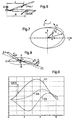
figure 4 montre les évolutions de la vitesse relative d'une pale par rapport à l'air en fonction de son azimut. - La
figure 5 illustre le mouvement de battement vertical d'une pale en fonction de son azimut. - La
figure 6 montre l'influence du battement vertical d'une pale sur la vitesse tangentielle d'un élément de pale. - La
figure 7 est relative à l'effet des forces de Coriolis. - La
figure 8 illustre les oscillations de traînée d'une pale au cours de sa rotation. - La
figure 9 est relative aux variations des élongations d'un amortisseur de traînée interpale en fonction de l'azimut d'une pale pour trois configurations dont une de base C1 et deux, C2 et C3, avec un déport identique des deux articulations de deux amortisseurs à une même pale, vers le dessus du giravion. - La
figure 10 montre l'influence de la traînée, du battement et du pas pour la configuration C1 relative à lafigure 9 . - La
figure 11 montre l'influence de la traînée, du battement et du pas pour la configuration C2 relative à lafigure 9 . - La
figure 12 illustre les effets de la variation cyclique du pas des pales sur l'angle de battement.
- The
figure 1 is a schematic perspective view of a head of a helicopter rotor according to the invention. - The
figure 2 is a schematic cross-sectional view of a sleeve connecting a blade to a lift rotor hub of a helicopter, and a view along II - II of thefigure 1 showing the articulation of a first interpale drag damper on the leading edge side of a blade, lower than the articulation of a second interpale drag damper on the trailing edge side of the same blade. - The
figure 3 represents an embodiment variant with respect to the embodiment according to thefigure 2 where the joints of two adjacent interpale dampers are offset above the plane containing the axes of variation of pitch and vertical beat. - The
figure 4 shows the evolution of the relative velocity of a blade relative to the air as a function of its azimuth. - The
figure 5 illustrates the vertical flapping movement of a blade as a function of its azimuth. - The
figure 6 shows the influence of the vertical beat of a blade on the tangential velocity of a blade element. - The
figure 7 is relative to the effect of Coriolis forces. - The
figure 8 illustrates the drag oscillations of a blade during its rotation. - The
figure 9 relates to the variations of the elongations of an interpale drag damper as a function of the azimuth of one blade for three configurations, one of which is a C1 base and two, C2 and C3, with an identical offset of the two joints of two dampers at one even pale, towards the top of the rotorcraft. - The
figure 10 shows the influence of the drag, the beat and the pitch for the C1 configuration relative to thefigure 9 . - The
figure 11 shows the influence of the drag, the beat and the pitch for C2 configuration relative to thefigure 9 . - The
figure 12 illustrates the effects of the cyclic variation of blade pitch on the beat angle.
Les éléments présents dans plusieurs figures distinctes sont affectés d'une seule et même référence.The elements present in several separate figures are assigned a single reference.
Sur la
Le mât rotor, fixé sur une boîte de transmission principale (BTP) de puissance, transmet à la structure du giravion la portance du rotor et supporte les pales 4 qui transforment l'énergie mécanique des moteurs en forces aérodynamiques.The rotor mast, attached to a main gearbox (BTP) of power, transmits rotorcraft lift to the rotorcraft structure and supports the
Ainsi, le moyeu 2 sert de point d'attache à chacune des pales 4 par l'intermédiaire d'un manchon 5 comprenant une chape radiale interne 6 équipée d'une articulation sphérique lamifiée 7 (ou butée sphérique) de liaison au moyeu 2 et d'une chape radiale externe 8 ou ferrure de retenue de la pale 4 correspondante.Thus, the
Dans ces conditions, chaque articulation sphérique lamifiée 7 autorise l'articulation de chaque pale 4 correspondante en battement vertical autour de l'axe de battement vertical 102, en traînée ainsi qu'en variation de pas autour de l'axe de variation de pas 101 de la pale. La variation de pas se fait par action de la commande de pas 9 entraînant une rotation de la pale 4 correspondante autour de l'axe de variation de pas 101.Under these conditions, each laminated spherical joint 7 allows the articulation of each
Bien entendu, les trois fonctions d'une butée sphérique peuvent être éventuellement réalisées par des moyens séparés tels que des axes de rotation, par exemple.Of course, the three functions of a spherical abutment may possibly be made by separate means such as axes of rotation, for example.
Selon l'organisation de la
Toujours selon l'organisation de la
En particulier, ces deux articulations 16 sont de part et d'autre de l'axe de variation de pas 101 de chaque pale 4, l'une au moins de ces articulations 16 étant décalée au dessus du plan P contenant les axes de variation de pas 101 et l'axe de battement vertical 102 c'est-à-dire selon le sens positif de l'axe orthogonal 103, orthogonal au plan P, cet axe orthogonal 103 étant orienté positivement vers le dessus du giravion.In particular, these two
Avantageusement, ces articulations 16 peuvent être d'ailleurs disposées sur chaque manchon 15 selon les représentations des
Toutefois, en variante, on peut concevoir de disposer les articulations 16 sur un autre support tel qu'une pale, par exemple, ou encore sur une manchette telle que décrite par les brevets
Quoiqu'il en soit, chaque articulation 16 est reprise, par exemple, par une ferrure en forme de chape double 13, 14 disposée sur un manchon 5 (ou tout autre support), de sorte qu'un tel manchon comprend, par rapport à la pale 4 correspondante une première ferrure 11 située du côté du bord d'attaque BA de ladite pale et une seconde ferrure 12 située du côté du bord de fuite BF de la même pale.Anyway, each hinge 16 is taken up, for example, by a double clevis-shaped
Plus précisément, selon l'invention et de façon avantageuse, l'articulation 16 (et par suite la ferrure 11) située vers le bord d'attaque BA d'une pale 4 est plus basse, par rapport à l'orientation positive de l'axe orthogonal 103, que l'articulation 16 (et par suite la ferrure 12 associée) située vers le bord de fuite BF de ladite pale 4.More specifically, according to the invention and advantageously, the hinge 16 (and consequently the bracket 11) located towards the leading edge BA of a
La
Le manchon 5 entraînant une pale 4 est lié à gauche de la
Toutefois, on remarque que la ferrure 12 est disposée au dessus du plan P formé par l'axe de variation du pas 101 et par l'axe de battement vertical 102, c'est-à-dire dans le sens positif de l'axe orthogonal 103, vers le dessus du giravion. A ce propos, on note que les axes de rotation 100 et orthogonal 103 sont parallèles quand le plan P est orthogonal à l'axe de rotation 100 du moyeu.However, it is noted that the fitting 12 is disposed above the plane P formed by the axis of variation of the
Par conséquent, les deux articulations 16 reliant respectivement la pale 4 considérée à deux amortisseurs de traînée interpales 15 « adjacents » sont disposées de part et d'autre de l'axe de variation du pas 101, l'articulation 16 située du côté du bord de fuite BF de la pale 4 étant décalée au dessus du plan P contenant les axes de variation de pas 101 et de battement vertical 102.Consequently, the two hinges 16 respectively connecting the
De plus, l'axe virtuel 104 reliant les deux centres des articulations de fixation respectives 16 de deux amortisseurs de trainée intercales 15 et adjacents à une pale 4 est décalé en élévation, par rapport à l'axe de variation de pas 101, à savoir positivement par rapport à l'axe de rotation 100.In addition, the
Ainsi, cet axe virtuel 104 présente un décalage C1 de manière à ne jamais couper l'axe de variation de pas 101.Thus, this
En particulier, l'articulation 16 relative à la ferrure 11 (côté bord d'attaque BA de la pale 4) est plus basse que l'articulation 16 relative à la ferrure 12 (côté bord de fuite BF de la pale 4).In particular, the
Dans ces conditions, et comme expliqué par la suite, il s'avère que :
- l'angle A1 formé par le plan P, contenant l'axe de battement vertical 102 et l'axe de variation de pas 101, avec l'axe reliant les deux centres des articulations de
fixation 16 d'un amortisseur de traînée interpale 15 à deux palesadjacentes 4 est situé dans une plage allant de un degré environ à sept degrés environ, - l'angle B1 formé par le plan P, contenant l'axe de battement vertical 102 et l'axe de variation de pas 101, avec l'axe virtuel 104 reliant les deux centres des articulations de
fixation respectives 16 de deux amortisseurs de traînée interpales 15 et adjacents à une pale 4 est situé dans une plage allant de sept degrés environ à vingt deux degrés environ.
- the angle A1 formed by the plane P, containing the
vertical beat axis 102 and thepitch variation axis 101, with the axis connecting the two centers of the attachment joints 16 of aninterpale drag damper 15 to twoadjacent blades 4 is in a range from about one degree to about seven degrees, - the angle B1 formed by the plane P, containing the
vertical beat axis 102 and thepitch variation axis 101, with thevirtual axis 104 connecting the two centers of the respective attachment joints 16 of two interpale dragdampers 15 and adjacent to ablade 4 is in a range of about seven degrees to twenty-two degrees.
En variante, on peut envisager que deux articulations 16 reliant la pale 4 à deux amortisseurs de traînée interpales adjacents 15 peuvent également être décalées selon un axe parallèle à l'axe orthogonal 103. Tel est le cas représenté sur la
Il importe de noter que les articulations 16 peuvent être installées sur tout type de manchon ou sur tout support adéquat (manchette, ....).It is important to note that the
La mise au point de l'invention résulte de recherches théoriques et d'expérimentations en relation avec des considérations tenant du fonctionnement aérodynamique d'un rotor de giravion, de la mécanique du rotor et de la technologie d'ensemble de l'appareil. Nous abordons ci-après ces questions de la façon la plus succincte possible afin de bien évaluer l'intérêt des solutions exposées précédemment.The development of the invention results from theoretical research and experimentation in relation to considerations relating to the aerodynamic operation of a rotorcraft rotor, rotor mechanics and the overall technology of the apparatus. We discuss below these questions of as succinctly as possible in order to properly evaluate the value of the solutions outlined above.
Conformément à la
Ainsi en vol de translation, la vitesse tangentielle U d'un élément de pale, situé à une distance R du centre O du rotor, se compose avec la vitesse de translation υ. La vitesse résultante V admet alors une composante tangentielle UR qui est la vitesse relative de la pale par rapport à l'air.Thus in translation flight, the tangential velocity U of a blade element, located at a distance R from the center O of the rotor, is composed with the translation speed υ. The resulting velocity V then admits a tangential component U R which is the relative speed of the blade with respect to the air.
A l'examen de la
- une pale en position alignée vers l'avant est telle que la vitesse UR d'un élément de pale au point A (rayon R) vaut UR=U,
- la vitesse relative d'un élément de pale par rapport à l'air au point B est égale à UR = U-υ ; pour cette raison, la pale est dite « reculante » car sa vitesse tangentielle est inférieure à υ (la pale recule par rapport au mouvement de translation),
- la vitesse relative d'un élément de pale par rapport à l'air au point C (position arrière) vaut UR =U,
- la vitesse relative d'un élément de pale par rapport à l'air au point D est égale à UR = U+υ ; pour cette raison, la pale est dite « avançante » car sa vitesse tangentielle est supérieure à υ (la pale avance par rapport au mouvement de translation),
- a blade in the forwardly aligned position is such that the speed U R of a blade element at point A (radius R) is equal to U R = U,
- the relative speed of a blade element relative to the air at point B is equal to U R = U-υ; for this reason, the blade is called "recoil" because its tangential velocity is less than υ (the blade retreats relative to the translational movement),
- the relative speed of a blade element with respect to the air at point C (rear position) is equal to U R = U,
- the relative speed of a blade element relative to the air at the point D is equal to U R = U + υ; for this reason, the blade is called "advancing" because its tangential velocity is greater than υ (the blade advances with respect to the translational movement),
Or, la portance Fn d'une pale est proportionnelle au carré de la vitesse relative UR. Par conséquent, il en résulte que :
- en B où la vitesse UR est minimale, la portance est minimale,
- de B à D, la portance croît et devient maximale en D où la vitesse relative UR est également maximale,
- de D à B, la portance décroît,
- en C et A, la valeur de la portance est moyenne.
- in B where the speed U R is minimal, the lift is minimal,
- from B to D, the lift increases and becomes maximum in D where the relative speed U R is also maximal,
- from D to B, the lift decreases,
- in C and A, the value of the lift is average.
En raison des effets de précession gyroscopique, il se fait qu'une pale de rotor réagit 90 degrés après la cause tendant à modifier sa portance. Par suite, si la vitesse relative est maximale en D (la cause), la portance (l'effet) n'est pas maximale en D mais en A, 90 degrés après le point de vitesse maximale.Due to the effects of gyroscopic precession, a rotor blade reacts 90 degrees after the cause of changing its lift. As a result, if the relative velocity is maximum in D (the cause), the lift (the effect) is not maximal in D but in A, 90 degrees after the point of maximum speed.
La pale étant articulée en battement, l'accroissement de portance tend à lever la pale par rapport à l'axe de battement vertical. En vertu de l'effet de précession gyroscopique précité, au point A de portance maximale FnMAXI correspond une levée maximale βmaxl de la pale de sorte que D à A, la pale suit une trajectoire ascendante, conformément à la
Par ailleurs, et selon la
Par exemple, si la pale monte, la vitesse U d'un élément de pale égale à ΩR en D devient ωrr dans la mesure où la pale considérée est munie d'une articulation de traînée. Or, l'élément de pale tend à conserver par inertie sa vitesse initiale U au cours du changement de trajectoire. Par suite, on en déduit que la vitesse ωr est supérieure à Ω : la pale oscille vers l'avant. Le moment de flexion qui serait créé dans le plan de la pale est annulé en raison de l'introduction de l'articulation de traînée.For example, if the blade rises, the speed U of a blade element equal to ΩR in D becomes ω r r since the blade considered is provided with a drag joint. However, the blade element tends to maintain its initial speed U inertia during the change of trajectory. As a result, we deduce that the speed ω r is greater than Ω: the blade oscillates forward. The bending moment that would be created in the plane of the blade is canceled due to the introduction of the drag joint.
En fait, la pale est sollicitée par des forces de Coriolis qui la font osciller dans le plan orthogonal à l'axe de traînée autour d'une position moyenne.In fact, the blade is solicited by Coriolis forces that make it oscillate in the plane orthogonal to the axis of drag around a mean position.
Les forces de Coriolis résultent de la superposition du mouvement relatif dû au battement et du mouvement d'entraînement dû à la rotation propre des pales. Conformément à la 
Comme indiqué sur la
- ° de C à A, la pale monte : la force d'inertie Fi, dirigée dans le sens de rotation fait osciller la pale vers l'avant,
- ° de A à C, la pale descend : la force d'inertie Fl, dirigée en sens contraire du sens de rotation, fait osciller la pale vers l'arrière,
- ° en A et C, la pale occupe une position moyenne.
- ° C to A, the blade rises: the inertia force F i , directed in the direction of rotation oscillates the blade forward,
- ° from A to C, the blade goes down: the inertia force F l , directed in the opposite direction of the direction of rotation, oscillates the blade towards the rear,
- ° in A and C, the blade occupies a middle position.
Dans ces conditions, les résultats des recherches effectuées par la demanderesse et exposés ci-après seront bien compris à partir des considérations précédentes.In these circumstances, the results of the research carried out by the applicant and described below will be well understood from the foregoing considerations.
Par conséquent, une étude théorique a été faite en vue de diminuer les charges dynamiques exercées sur des amortisseurs de traînée interpales, ces charges générant, bien évidemment par voie de conséquence, également des efforts dynamiques sur les pales et l'ensemble des autres éléments constitutifs d'un rotor de giravion.Consequently, a theoretical study has been made with a view to reducing the dynamic loads exerted on interpale drag dampers, these loads generating, of course consequently, also dynamic forces on the blades and all the other constituent elements. of a rotorcraft rotor.
La réduction de ces charges équivaut à diminuer les débattements importants imposés aux amortisseurs sous l'effet de l'excitation périodique du rotor. La recherche d'un abaissement des débattements imposés à un amortisseur a pour objectif une amélioration des performances des amortisseurs, notamment en terme de durée de vie, et de façon subséquente une diminution des sollicitations mécaniques des différents éléments d'un rotor de giravion.The reduction of these charges is equivalent to reducing the large deflections imposed on the dampers under the effect of the periodic excitation of the rotor. The search for a lowering of the deflections imposed on a damper aims to improve the performance of the dampers, particularly in terms of service life, and subsequently a reduction in mechanical stresses of the various elements of a rotorcraft rotor.
Concrètement, une étude relative au rotor d'un hélicoptère de la classe de l'hélicoptère NH90 de la demanderesse montre un effet très avantageux d'un même décalage des points d'articulation 16 de deux amortisseurs de traînée interpales 15 à une même pale 4. Ce décalage étant noté d conformément à la
Les évolutions des allongements globaux (statiques et dynamiques) pour ces trois configurations C1, C2 et C3 sont respectivement représentées sur la
La configuration C2 est la plus favorable car elle permet une réduction des allongements dynamiques par un facteur de l'ordre 2.The C2 configuration is the most favorable because it allows a reduction of dynamic elongations by a factor of
Ce décalage selon le sens positif de l'axe 103 équivaut sensiblement à une conicité supplémentaire de l'ordre de 0,17 rd, soit près de dix degrés, les articulations 16 étant à 0,345m de la butée sphérique lamifiée 7.This offset in the positive direction of the
Les
Ainsi, on repère sur ces deux figures les contributions CA, CB et CC respectivement relatives aux effets de la traînée seule, de la traînée et du battement conjugués et enfin de la traînée conjuguée au battement et au pas.Thus, these two figures show the contributions CA, CB and CC respectively relating to the effects of drag alone, drag and beat conjugate and finally the drag conjugate beat and step.
Les axes des abscisses et des ordonnées correspondent également respectivement à l'azimut d'une pale et aux déplacements globaux de l'amortisseur.The abscissa and ordinate axes also correspond respectively to the azimuth of a blade and to the overall displacements of the damper.
On remarque ainsi que la prise en compte du battement réduit l'effet de la traînée seule, en raison de l'action des forces de Coriolis.We note that taking into account the beat reduces the effect of drag alone, due to the action of Coriolis forces.
Enfin, on retient qu'une augmentation excessive du décalage d devient pénalisante dans la mesure où une partie des efforts des amortisseurs peut être introduite dans la chaîne de commande de pas, ce qui par ailleurs, pourrait conduire à une instabilité de type « entraînement de manche », connu par l'homme du métier.Finally, it is retained that an excessive increase of the offset d becomes penalizing insofar as a part of the forces of the dampers can be introduced into the pitch control chain, which moreover could lead to an instability of the "drive-off" type. sleeve ", known to those skilled in the art.
En fait et conformément à la
Par ailleurs, la
Ces effets sont dus aux variations du pas cyclique combiné au pas général qui permettent le basculement du plan rotor et le vol d'avancement d'un giravion.These effects are due to the variations of the cyclic pitch combined with the general pitch which allow the tilting of the rotor plane and the forward flight of a rotorcraft.
Bien entendu, les articulations de traînée sont destinées à permettre ces mouvements.Of course, the drag joints are intended to allow these movements.
Plus précisément, la
Il apparaît encore que la longueur de l'arc AB est supérieure à celle de l'arc BC (B' : point milieu entre A et C), la vitesse de la pale sur l'arc BC est inférieure à sa vitesse sur l'arc AB.It appears again that the length of the arc AB is greater than that of the arc BC (B ': middle point between A and C), the speed of the blade on the arc BC is lower than its speed on the AB arc.
En d'autres termes et en raison de l'effet des forces de Coriolis susmentionnées, une pale montante (battement vertical) est ralentie dans son mouvement de façon qu'elle tend à décrire des déplacements égaux dans l'espace dans des temps égaux ce qui tend à maintenir sensiblement constante l'énergie cinétique et par suite la vitesse de ladite pale par inertie. Cette vitesse tend également à devenir constante sur l'arc CDA.In other words and because of the effect of the aforementioned Coriolis forces, a rising blade (vertical beat) is slowed in its motion so that it tends to describe equal displacements in space in equal times this which tends to maintain substantially constant kinetic energy and consequently the speed of said blade by inertia. This velocity also tends to become constant over the CDA arc.
Il est donc légitime de considérer que le battement vertical des pales tend à réduire les déplacements en traînée et à maintenir de la sorte les pales équidistantes, ce qui est illustré en terme de conséquence par les
Autrement dit, il est légitime de considérer que la participation du mouvement de battement vertical peut limiter les débattements d'un amortisseur de traînée interpale.In other words, it is legitimate to consider that the participation of the vertical flapping movement can limit the deflections of an interpale drag damper.
Or, nous avons établi que le décalage des articulations des amortisseurs de traînée selon le sens positif de l'axe 103 équivaut, dans le présent exemple de réalisation, à une conicité supplémentaire de l'ordre de dix degrés.However, we have established that the offset of the drag damping joints in the positive direction of the
En d'autres termes, un tel décalage peut être considéré comme générateur d'une augmentation du battement vertical d'une pale et par conséquent d'une réduction des débattements de l'amortisseur interpale correspondant, conformément aux résultats selon la
Par ailleurs, une campagne d'expérimentation en vol avec un hélicoptère SUPER PUMA MKII de la demanderesse démontre qu'une position croisée (différentielle) des articulations 16 est intéressante pour ce type d'appareil. L'application a été menée avec une configuration C4 relative à un décalage d de l'articulation 16 au bord de fuite d'une pale de 0,035m au dessus du plan P, l'articulation 16 au niveau du bord d'attaque de la même pale étant décalée de -0,005m c'est-à-dire vers le dessous du plan P. Autrement dit, les deux articulations 16 de ladite pale sont bien décalées selon l'axe 103, orthogonal au plan P, et l'articulation 16 du côté du bord de fuite de la pale est bien au dessus du plan P. La configuration initiale, sans décalage des deux articulations 16 est notée CO.Moreover, an in-flight experimentation campaign with a SUPER PUMA MKII helicopter of the Applicant demonstrates that a cross position (differential) of the
Le tableau ci-après regroupe les résultats des mesures effectuées d'une part en vol de palier, à des vitesses de 80, 100, 120 et 140 noeuds (kts) et d'autre part en virage à des facteurs de charge de 1,4 - 1,8 et 2g, g étant l'accélération de la pesanteur :
On constate qu'une réduction importante des débattements dynamiques d'un amortisseur de traînée interpale peut être obtenu par un décalage différentiel des articulations 16 tel que celui-ci dessus étudié.It can be seen that a significant reduction in the dynamic displacements of an interpale drag damper can be obtained by a differential offset of the
En effet, on observe un gain important d'au moins 35% aussi bien en vol de palier qu'en virage, et cela sans être affecté par des variations de centrage de l'hélicoptère.Indeed, there is a significant gain of at least 35% in both landing flight and cornering, and this without being affected by centering variations of the helicopter.
Ce gain permet d'augmenter dés lors la durée de vie d'un tel amortisseur d'un facteur 3 à 4.This gain makes it possible to increase the lifetime of such a shock absorber by a factor of 3 to 4.
Il importe encore de noter que des résultats semblables peuvent être aussi obtenus avec des articulations 16 telles que l'articulation 16 au niveau du bord de fuite est à 0,075m, au dessus du plan P (configuration C5), celle relative au bord d'attaque étant à 0,005m en dessous de ce plan.It is also important to note that similar results can also be obtained with
On observe que l'angle A1 relatif aux configurations C4 et C5 vaut respectivement dix degrés et vingt deux degrés. En fait, la plage optimale pour l'angle A1 est sensiblement comprise entre sept et vingt deux degrés compte tenu des recherches spécifiques effectuées par ailleurs sur l'hélicoptère EC155 de la demanderesse. Dans ces conditions, il en résulte également les valeurs de l'angle B1 présentées précédemment.It is observed that the angle A1 relative to the configurations C4 and C5 is respectively ten degrees and twenty two degrees. In fact, the optimum range for the angle A1 is substantially between seven and twenty-two degrees, taking into account the specific research carried out on the applicant's EC155 helicopter. Under these conditions, it also results in the values of the angle B1 presented above.
Bien évidemment, la description précédente appliquée à un rotor quadripale vaut également pour tout rotor comportant au moins trois pales, c'est-à-dire susceptible de correspondre à une architecture avec des tirants interpales de rappel élastique.Of course, the preceding description applied to a quadripal rotor also applies to any rotor comprising at least three blades, that is to say capable of corresponding to an architecture with interpalescent elastic return rods.
Naturellement, la présente invention est sujette à de nombreuses variations quant à sa mise en oeuvre. Bien que plusieurs variantes aient été décrites, on comprend bien qu'il n'est pas concevable d'identifier de manière exhaustive toutes les variantes possibles. Il est bien sûr envisageable de remplacer un moyen décrit par un moyen équivalent sans sortir du cadre de la présente invention.Naturally, the present invention is subject to many variations as to its implementation. Although several variants have been described, it is understandable that it is not conceivable to exhaustively identify all the possible variants. It is of course conceivable to replace a means described by equivalent means without departing from the scope of the present invention.
Claims (9)
caractérisé en ce que, l'une au moins des dites articulations (16) est décalée au dessus du plan P contenant l'axe de variation de pas (101) et l'axe de battement vertical (102), c'est-à-dire selon le sens positif de l'axe orthogonal (103) au plan P, cet axe orthogonal (103) étant orienté positivement vers le dessus du giravion.Rotor rotor (1) having a hub (2) rotatably rotated about an axis of rotation (100) positively oriented towards the top of the rotorcraft, at least three blades (4) fixed to the hub (2) each via joints (7) in vertical beating, drag and pitch, each blade (4) having a pitch variation axis (101), a leading edge (BA) and a trailing edge (BF), the rotor (1) further comprising interpale drag dampers (15) each connected to two adjacent blades (4) respectively via at least two spherical joints (16), or ball joints, the two joints (16) respectively connecting a blade (4) with two adjacent interpale drag dampers (15) being disposed on either side of the pitch variation axis (101) of the blade (4),
characterized in that at least one of said hinges (16) is shifted above the plane P containing the pitch variation axis (101) and the vertical flap axis (102), that is, say in the positive direction of the orthogonal axis (103) to the plane P, this orthogonal axis (103) being oriented positively towards the top of the rotorcraft.
caractérisé en ce que les deux articulations (16) reliant la pale (4) à deux amortisseurs de traînée interpales (15) sont, en outre, décalées selon l'axe orthogonal (103) audit plan P.Rotor (1) according to claim 1,
characterized in that the two hinges (16) connecting the blade (4) to two interpale drag dampers (15) are further shifted along the orthogonal axis (103) to said plane P.
caractérisé en ce que celle des deux articulations (16), reliant la pale (4) à deux amortisseurs de traînée interpales (15), qui est disposée du côté du bord d'attaque(BA) de la pale (4) est plus basse, par rapport à l'orientation positive de l'axe orthogonal (103) au plan P que l'articulation (16) disposée du côté du bord de fuite de la pale (4).Rotor (1) according to claims 1 or 2,
characterized in that that of the two hinges (16), connecting the blade (4) to two interpale drag dampers (15), which is disposed on the leading edge side (BA) of the blade (4) is lower, relative to the positive orientation of the orthogonal axis (103) in the plane P than the hinge (16) disposed on the trailing edge of the blade (4).
caractérisé en ce que l'angle A1 formé par le plan P et l'axe reliant les deux centres des articulations (16) de fixation d'un amortisseur de traînée interpale (15) à deux pales adjacentes (4) est situé dans une plage allant de un degré environ à sept degrés environ.Rotor (1) according to one of Claims 1 to 3,
characterized in that the angle A1 formed by the plane P and the axis connecting the two centers of the joints (16) for fixing an interpale drag damper (15) to two adjacent blades (4) is situated in a range from about one degree to about seven degrees.
caractérisé en ce que l'angle B1 formé par le plan P et l'axe reliant les deux centres des articulations (16) de fixation respectives de deux amortisseurs de traînée interpales (15) et adjacents à la pale (4) est situé dans une plage allant de sept degrés environ à vingt deux degrés environ.Rotor (1) according to one of Claims 1 to 3,
characterized in that the angle B1 formed by the plane P and the axis connecting the two centers of the respective attachment joints (16) of two interpale drag dampers (15) and adjacent to the blade (4) is located in a range from about seven degrees to about twenty-two degrees.
caractérisé en ce que les deux articulations (16) reliant respectivement la pale (4) considérée à deux amortisseurs de traînée interpales (15) adjacents sont disposées sur un manchon (5) intermédiaire comprenant du côté radial externe une ferrure de retenue (8) de la pale (4) et du côté radial interne une chape (6) équipée des articulations (7) de l'ensemble pale (4) et manchon (5) au moyeu.Rotor (1) according to one of Claims 1 to 5,
characterized in that the two joints (16) respectively connecting the respective blade (4) to two adjacent interpale drag dampers (15) are arranged on an intermediate sleeve (5) comprising on the outer radial side a retaining fitting (8) of the blade (4) and the inner radial side a clevis (6) equipped with the joints (7) of the blade assembly (4) and sleeve (5) to the hub.
caractérisé en ce qu'il comporte au moins trois pales (4).Rotor (1) according to one of Claims 1 to 6,
characterized in that it comprises at least three blades (4).
caractérisé en ce que les articulations (7) de battement vertical, de traînée et de pas d'une pale (4) au moyeu (2) sont réalisées au moyen d'une seule butée sphérique lamifiée.Rotor (1) according to one of Claims 1 to 7,
characterized in that the hinges (7) of vertical flapping, drag and pitch of a blade (4) at the hub (2) are formed by means of a single laminated spherical abutment.
caractérisé en ce que l'axe virtuel (104), reliant les centres des articulations (16) de fixation respectives de deux amortisseurs de trainée interpales (15) et adjacents à la pale (4), est décalé en élévation par rapport à l'axe de variation de pas (101) de la pale.Rotor (1) according to any one of the preceding claims,
characterized in that the virtual axis (104), connecting the centers of the respective attachment joints (16) of two interpale drag dampers (15) and adjacent to the blade (4), is offset in elevation relative to the pitch variation axis (101) of the blade.
Applications Claiming Priority (1)
| Application Number | Priority Date | Filing Date | Title |
|---|---|---|---|
| FR0611488A FR2910877B1 (en) | 2006-12-28 | 2006-12-28 | IMPROVEMENT TO ROTORS OF GIRAVIONS EQUIPPED WITH INTERPAL SHOCK ABSORBERS |
Publications (2)
| Publication Number | Publication Date |
|---|---|
| EP1939087A1 true EP1939087A1 (en) | 2008-07-02 |
| EP1939087B1 EP1939087B1 (en) | 2009-07-01 |
Family
ID=38229936
Family Applications (1)
| Application Number | Title | Priority Date | Filing Date |
|---|---|---|---|
| EP07023730A Active EP1939087B1 (en) | 2006-12-28 | 2007-12-07 | Rotorcraft rotor improvement equipped with inter-blade shock absorbers |
Country Status (3)
| Country | Link |
|---|---|
| US (1) | US8123483B2 (en) |
| EP (1) | EP1939087B1 (en) |
| FR (1) | FR2910877B1 (en) |
Cited By (1)
| Publication number | Priority date | Publication date | Assignee | Title |
|---|---|---|---|---|
| EP2803571A1 (en) | 2013-05-16 | 2014-11-19 | Airbus Helicopters | Resilient hinged connection between a lag-lead damper and a rotor blade |
Families Citing this family (15)
| Publication number | Priority date | Publication date | Assignee | Title |
|---|---|---|---|---|
| US20110044223A1 (en) * | 2006-08-23 | 2011-02-24 | Electronics And Telecommunications Research Institute | Mbms data transmission and receiving in packet based on cellular system |
| FR2933068B1 (en) * | 2008-06-27 | 2011-02-25 | Eurocopter France | BLADE FOR REDUCING MOVEMENTS IN TRAINING OF SAID BLADE AND METHOD FOR REDUCING SUCH MOVEMENT IN TRAINEE. |
| FR2954274B1 (en) * | 2009-12-17 | 2012-02-24 | Eurocopter France | VIBRATION DAMPER MECHANISM, AND FLYING APPARATUS PROVIDED WITH A CARRIER STRUCTURE AND A ROTOR HAVING SUCH A MECHANISM |
| KR20150030191A (en) * | 2012-04-05 | 2015-03-19 | 로오드 코포레이션 | Motion controlled helicopter and rotation rate switched fluid lead lag damper |
| US9616996B2 (en) | 2013-07-29 | 2017-04-11 | Sikorsky Aircraft Corporation | Stiff inplane elastomeric rotorhead |
| CH710026A1 (en) * | 2014-08-27 | 2016-02-29 | Marenco Swisshelicopter Ag | Rotor blade coupling device and rotor head for rotorcraft. |
| CH710046A2 (en) | 2014-08-27 | 2016-02-29 | Marenco Swisshelicopter Ag | Rotor blade coupling device of a rotor head for rotorcraft. |
| US9234556B1 (en) | 2014-08-29 | 2016-01-12 | Aktiebolaget Skf | Elastomer having tear reducing contoured edges |
| EP3168146B1 (en) | 2015-11-11 | 2019-06-05 | kopter group ag | Rotor blade coupling device of a rotor head for a rotorcraft |
| US10472057B2 (en) * | 2016-02-16 | 2019-11-12 | Bell Helicopter Textron Inc. | Rotor assembly with high lock-number blades |
| US10457388B2 (en) * | 2016-02-16 | 2019-10-29 | Bell Helicopter Textron, Inc. | Rotor assembly with high lock-number blades |
| FR3053312B1 (en) * | 2016-06-29 | 2019-07-19 | Airbus Helicopters | ROTOR AND AIRCRAFT PROVIDED WITH SUCH A ROTOR |
| US10773798B2 (en) * | 2017-09-29 | 2020-09-15 | Bell Textron Inc. | Rotor hub with blade-to-blade dampers attached to the pitch change axis |
| WO2019217532A1 (en) * | 2018-05-08 | 2019-11-14 | Avx Aircraft Company | Rotor hub |
| FR3126494B1 (en) * | 2021-08-31 | 2023-07-21 | Airbus Helicopters | rotor shock absorber test bench |
Citations (74)
| Publication number | Priority date | Publication date | Assignee | Title |
|---|---|---|---|---|
| FR948640A (en) * | 1946-05-30 | 1949-08-05 | Bristol Aeroplane Co Ltd | Improvements to lift rotors in rotary wing aircraft |
| FR2630703A1 (en) * | 1988-04-29 | 1989-11-03 | Aerospatiale | ROTOR HEAD OF GIRAVION WITH INTERPAL ELASTIC RECALL TIES WITH INCORPORATED DAMPING |
| DE68915788T2 (en) | 1988-10-31 | 1994-10-20 | Sepracor Inc | MEMBRANE AFFINITY DEVICE AND CLEANING METHOD. |
| DE69207369T2 (en) | 1991-07-05 | 1996-06-13 | Toyoda Chuo Kenkyusho Kk | METHOD FOR REGENERATING COATED PLASTIC WASTE |
| DE69306874T2 (en) | 1992-07-15 | 1997-07-03 | Roquette Freres | Thermoformable composition, process for its manufacture and its use in the manufacture of thermoformed articles |
| DE69312246T2 (en) | 1992-12-07 | 1998-01-08 | Sedepro | Process and apparatus for continuously mixing rubber |
| FR2750948A1 (en) * | 1996-07-12 | 1998-01-16 | Eurocopter France | Helicopter rotor position stop |
| DE69312852T2 (en) | 1992-09-22 | 1998-01-22 | Petoca Ltd | Process for the production of pitch-based activated carbon fibers |
| DE68928567T2 (en) | 1988-12-27 | 1998-08-27 | Asahi Chemical Ind | POROUS CRYSTALLIZED AROMATIC POLYCARBONATE PREPOLYMER, A POROUS CRYSTALLIZED AROMATIC POLYCARBONATE AND METHOD FOR PRODUCING THE SAME |
| DE69419146T2 (en) | 1993-04-28 | 1999-10-14 | Dow Chemical Co | MIXTURES OF GRAFT MODIFIED IN ESSENTIAL LINEAR ETHYLENE POLYMERS AND OTHER THERMOPLASTIC POLYMERS |
| DE19954313A1 (en) | 1999-11-11 | 2001-05-17 | Bayer Ag | Polycarbonate molding compounds |
| DE19953793A1 (en) | 1999-11-09 | 2001-05-17 | Cognis Deutschland Gmbh | Surfactant granules with an improved dissolution rate |
| DE19953796A1 (en) | 1999-11-09 | 2001-05-17 | Cognis Deutschland Gmbh | Solid washing, rinsing and cleaning agents |
| DE19956803A1 (en) | 1999-11-25 | 2001-06-13 | Cognis Deutschland Gmbh | Surfactant granules with an improved dissolution rate |
| DE19958398A1 (en) | 1999-12-03 | 2001-06-13 | Cognis Deutschland Gmbh | Use of partial glyceride polyglycol ethers |
| DE19956802A1 (en) | 1999-11-25 | 2001-06-13 | Cognis Deutschland Gmbh | Detergent tablets |
| DE19960494A1 (en) | 1999-12-15 | 2001-06-21 | Knoll Ag | Device and method for producing solid active substance-containing forms |
| DE19956483A1 (en) | 1999-11-24 | 2001-06-28 | Basf Coatings Ag | Lacquered molded plastic parts, process for their production and their use |
| DE19962886A1 (en) | 1999-12-24 | 2001-07-05 | Cognis Deutschland Gmbh | Surfactant granules with an improved dissolution rate |
| DE19962883A1 (en) | 1999-12-24 | 2001-07-12 | Cognis Deutschland Gmbh | Detergent tablets |
| DE19962859A1 (en) | 1999-12-24 | 2001-07-12 | Cognis Deutschland Gmbh | Solid detergent |
| DE69427539T2 (en) | 1993-08-30 | 2002-04-04 | Masland Ind Inc | RECYCLING WASTE CARPET |
| DE69709015T2 (en) | 1996-10-07 | 2002-05-02 | Toyo Ink Mfg Co | Surface-treated organic pigment and process for its production |
| DE69428309T2 (en) | 1993-07-19 | 2002-07-04 | Novacor Chem Int | particle sizing |
| DE69707763T2 (en) | 1996-06-25 | 2002-08-01 | Camillo Scotto | Method and device for manufacturing pipes from reused thermoplastic |
| DE69711597T2 (en) | 1996-01-08 | 2002-10-31 | Andersen Corp | CONSTRUCTION PLASTIC AND WOOD FIBER COMPOSITE |
| DE69807708T2 (en) | 1997-08-27 | 2003-01-02 | Dow Chemical Co | ELASTOMERS WITH IMPROVED PROCESSABILITY |
| DE69622375T2 (en) | 1995-01-20 | 2003-03-06 | Du Pont | METHOD FOR PRODUCING GRANULES FROM AMORPHOUS POLYESTERS |
| DE69715082T2 (en) | 1996-05-06 | 2003-05-22 | Morton Int Inc | Process for the production of epoxy powder coating compositions for texture-effect coating for coating heat-sensitive substrates |
| DE69715781T2 (en) | 1996-12-26 | 2003-08-14 | Morton Int Inc | Thermally and UV curable powder coatings |
| DE69628188T2 (en) | 1995-11-30 | 2004-04-01 | Dow Global Technologies, Inc., Midland | MONOOLEFIN-POLYEN-COPOLYMERS, METHOD FOR THE PRODUCTION THEREOF, COMPOSITIONS CONTAINING THEM AND MOLDED PARTS THEREOF |
| DE69908565T2 (en) | 1998-02-24 | 2004-05-06 | Mitsubishi Rayon Co., Ltd. | OPTICAL PLASTIC FIBER, FIBER OPTICAL CABLE, FIBER OPTICAL CABLE WITH PLUG, METHOD FOR PRODUCING POLYMER BASED ON METHYL METHACRYLATE AND METHOD FOR PRODUCING AN OPTICAL PLASTIC FIBER |
| DE69725985T2 (en) | 1996-05-28 | 2004-05-06 | Idemitsu Petrochemical Co., Ltd. | METHOD AND DEVICE FOR PRODUCING BLOW-MOLDED OBJECTS |
| DE10257377A1 (en) | 2002-12-09 | 2004-07-08 | Basf Coatings Ag | Aqueous color and / or effect coating material and its use |
| DE69630762T2 (en) | 1995-10-16 | 2004-09-23 | Bristol-Myers Squibb Co. | Nutrition for diabetics with controlled absorption of carbohydrates |
| DE10333927A1 (en) | 2003-07-25 | 2005-02-24 | Bayer Materialscience Ag | Polyformal as coextrusion protective layer on polycarbonate |
| DE10345043A1 (en) | 2003-09-27 | 2005-04-21 | Rhein Chemie Rheinau Gmbh | Microgel-containing composition |
| DE10342822A1 (en) | 2003-09-17 | 2005-04-21 | Coperion Werner & Pfleiderer | Method and extruder for producing syntactic plastic |
| DE10343964A1 (en) | 2003-09-19 | 2005-04-28 | Johannes Hauer | Processing recycled plastics comprising polyethylene and polypropylene comprises mixing cleaned plastics particles with selected mediators to produce a meltable plastics mixture useful for making shaped products |
| DE10349144A1 (en) | 2003-10-17 | 2005-05-12 | Roehm Gmbh | Polymer mixture for injection mouldings with a matt surface, e.g. exterior vehicle parts, comprises an acrylic matrix, a crosslinked acrylic impact modifier and plastic particles with a specified range of particle sizes |
| EP1533101A1 (en) | 2003-11-06 | 2005-05-25 | Entex Rust & Mitschke GmbH | Planetary roller extruder for compounding and extruding plastic masses |
| DE10352444A1 (en) | 2003-11-10 | 2005-06-09 | Mitsubishi Polyester Film Gmbh | Adhesion-promoted, heat-sealable and peelable polyester film, process for its preparation and its use |
| DE10352432A1 (en) | 2003-11-10 | 2005-06-09 | Mitsubishi Polyester Film Gmbh | White, heat-sealable, peelable polyester film, process for its preparation and its use |
| DE10352439A1 (en) | 2003-11-10 | 2005-06-09 | Mitsubishi Polyester Film Gmbh | Process for the preparation of a heat-sealable and peelable polyester film |
| DE10352440A1 (en) | 2003-11-10 | 2005-06-09 | Mitsubishi Polyester Film Gmbh | Process for the preparation of a coextruded, peelable polyester film |
| DE10352430A1 (en) | 2003-11-10 | 2005-06-09 | Mitsubishi Polyester Film Gmbh | Peelable polyester film with improved oxygen barrier, process for its preparation and its use |
| DE10352431A1 (en) | 2003-11-10 | 2005-06-09 | Mitsubishi Polyester Film Gmbh | Peelable polyester film with automatic venting, process for their preparation and their use |
| DE10351463A1 (en) | 2003-11-04 | 2005-06-23 | Man Nutzfahrzeuge Ag | Motor vehicle rigid steering axle has steering rod and stub axle control lever positioned below level of axle |
| DE10354546A1 (en) | 2003-11-21 | 2005-06-23 | Bayer Materialscience Ag | Polycarbonate solid shaped articles with improved optical and processing properties |
| DE102004048794A1 (en) | 2003-11-17 | 2005-06-23 | Battenfeld Extrusionstechnik Gmbh | Plastic extruding unit, comprises a filling section for charging the extruder with material to be plastified, an opening, and a stopper |
| DE10354379A1 (en) | 2003-11-20 | 2005-06-23 | Röhm GmbH & Co. KG | A molding composition containing a matting agent |
| DE10356821A1 (en) | 2003-12-05 | 2005-07-07 | Bayer Materialscience Ag | Process for mixing polymer melts with additives |
| DE102004002159A1 (en) | 2004-01-15 | 2005-08-11 | Fraunhofer-Gesellschaft zur Förderung der angewandten Forschung e.V. | Removal of contamination from polymers, especially for recycling, involves injection and removal of supercritical carbon dioxide in extruder |
| DE102004004230A1 (en) | 2004-01-27 | 2005-08-11 | Basf Ag | Thermoplastic molding compounds based on styrene copolymers and polyamides |
| DE102004004237A1 (en) | 2004-01-27 | 2005-08-18 | Woco Industrietechnik Gmbh | Process for the production of microporous plastic products and the plastic products obtainable by this process and a plastic starting material |
| DE60012108T2 (en) | 1999-11-02 | 2005-08-25 | Nippon Shokubai Co., Ltd. | Continuous production process of water-absorbing polymers |
| DE102005007952A1 (en) | 2004-03-04 | 2005-09-22 | Battenfeld Extrusionstechnik Gmbh | Ring for a planetary extruder, comprises at least one bore which contains a thread, and which can house a measurement unit |
| DE102004023085A1 (en) | 2004-05-11 | 2005-12-15 | Clariant Gmbh | Dialkylphosphinic acid salts, a process for their preparation and their use |
| DE69827497T2 (en) | 1997-08-15 | 2006-01-05 | Minnesota Mining And Mfg. Co., Saint Paul | SEALING METHOD AND SUBJECT |
| DE102004032694A1 (en) | 2004-07-06 | 2006-02-02 | Fraunhofer-Gesellschaft zur Förderung der angewandten Forschung e.V. | Swellable material composition and its use |
| DE102004034039A1 (en) | 2004-07-13 | 2006-02-09 | Technamation Technical Europe Gmbh | Extrusion method for processing raw material in extruder to extrudate comprises filling the material; homogenizing; exhausting; transporting; mixing, milling; transporting material to ejection zone; condensing; and transporting extrudate |
| DE102004038774A1 (en) | 2004-08-09 | 2006-02-23 | Tesa Ag | Laser film of an at least single-layer carrier layer of a transparent film, which is coated on one side with a self-adhesive |
| DE102004044086A1 (en) | 2004-09-09 | 2006-03-16 | Tesa Ag | Thermally crosslinked acrylate hotmelts |
| DE102004044085A1 (en) | 2004-09-09 | 2006-03-16 | Tesa Ag | Pressure-sensitive adhesive with dual crosslinking mechanism |
| DE102004046228A1 (en) | 2004-09-22 | 2006-03-23 | Betrem Gmbh & Co. Kg | Sewage sludge is reduced to grains by admixture with chalk and extrusion through perforated drum wall for incineration |
| DE102004048773A1 (en) | 2004-10-07 | 2006-04-13 | Degussa Ag | Hydroxyl terminated uretdione group-containing polyurethane compounds |
| DE10340977B4 (en) | 2003-09-05 | 2006-04-13 | Ticona Gmbh | Polyoxymethylene homo- and copolymers, their preparation and use |
| DE10340976B4 (en) | 2003-09-05 | 2006-04-13 | Ticona Gmbh | Polyoxymethylene multiblock copolymers, their preparation and use |
| DE102004053929A1 (en) | 2004-11-05 | 2006-05-11 | Coperion Waeschle Gmbh & Co. Kg | Continuous processing of polypropylene, polyamide or polyester granules from underwater granulation, involves drying and heating, mixing, cooling and washing with cooling water and then continuous centrifugal drying |
| DE102004026799B4 (en) | 2004-06-02 | 2006-05-18 | Clariant Gmbh | Press granulated flame retardant composition, process for its preparation and its use |
| DE60206271T2 (en) | 2001-07-02 | 2006-06-22 | Magma Trade Di Mauro Magni & C.Snc | METHOD AND DEVICE FOR PRODUCING FILLED THERMOPLASTIC POLYMERS |
| DE102004060966A1 (en) | 2004-12-17 | 2006-06-29 | Basf Coatings Ag | Pseudoplastic curable mixtures, process for their preparation and their use |
| DE102004061068A1 (en) | 2004-12-18 | 2006-07-06 | Battenfeld Extrusionstechnik Gmbh | Cooling of a plastic processing machine |
| DE102004061185A1 (en) | 2004-12-20 | 2006-07-06 | Basf Coatings Ag | Multi-component systems, process for their preparation and their use |
-
2006
- 2006-12-28 FR FR0611488A patent/FR2910877B1/en not_active Expired - Fee Related
-
2007
- 2007-12-07 EP EP07023730A patent/EP1939087B1/en active Active
- 2007-12-28 US US11/965,786 patent/US8123483B2/en not_active Expired - Fee Related
Patent Citations (76)
| Publication number | Priority date | Publication date | Assignee | Title |
|---|---|---|---|---|
| FR948640A (en) * | 1946-05-30 | 1949-08-05 | Bristol Aeroplane Co Ltd | Improvements to lift rotors in rotary wing aircraft |
| FR2630703A1 (en) * | 1988-04-29 | 1989-11-03 | Aerospatiale | ROTOR HEAD OF GIRAVION WITH INTERPAL ELASTIC RECALL TIES WITH INCORPORATED DAMPING |
| DE68915788T2 (en) | 1988-10-31 | 1994-10-20 | Sepracor Inc | MEMBRANE AFFINITY DEVICE AND CLEANING METHOD. |
| DE68928567T2 (en) | 1988-12-27 | 1998-08-27 | Asahi Chemical Ind | POROUS CRYSTALLIZED AROMATIC POLYCARBONATE PREPOLYMER, A POROUS CRYSTALLIZED AROMATIC POLYCARBONATE AND METHOD FOR PRODUCING THE SAME |
| DE69207369T2 (en) | 1991-07-05 | 1996-06-13 | Toyoda Chuo Kenkyusho Kk | METHOD FOR REGENERATING COATED PLASTIC WASTE |
| DE69306874T2 (en) | 1992-07-15 | 1997-07-03 | Roquette Freres | Thermoformable composition, process for its manufacture and its use in the manufacture of thermoformed articles |
| DE69312852T2 (en) | 1992-09-22 | 1998-01-22 | Petoca Ltd | Process for the production of pitch-based activated carbon fibers |
| DE69312246T2 (en) | 1992-12-07 | 1998-01-08 | Sedepro | Process and apparatus for continuously mixing rubber |
| DE69419146T2 (en) | 1993-04-28 | 1999-10-14 | Dow Chemical Co | MIXTURES OF GRAFT MODIFIED IN ESSENTIAL LINEAR ETHYLENE POLYMERS AND OTHER THERMOPLASTIC POLYMERS |
| DE69428309T2 (en) | 1993-07-19 | 2002-07-04 | Novacor Chem Int | particle sizing |
| DE69427539T2 (en) | 1993-08-30 | 2002-04-04 | Masland Ind Inc | RECYCLING WASTE CARPET |
| DE69622375T2 (en) | 1995-01-20 | 2003-03-06 | Du Pont | METHOD FOR PRODUCING GRANULES FROM AMORPHOUS POLYESTERS |
| DE69630762T2 (en) | 1995-10-16 | 2004-09-23 | Bristol-Myers Squibb Co. | Nutrition for diabetics with controlled absorption of carbohydrates |
| DE69628188T2 (en) | 1995-11-30 | 2004-04-01 | Dow Global Technologies, Inc., Midland | MONOOLEFIN-POLYEN-COPOLYMERS, METHOD FOR THE PRODUCTION THEREOF, COMPOSITIONS CONTAINING THEM AND MOLDED PARTS THEREOF |
| DE69711597T2 (en) | 1996-01-08 | 2002-10-31 | Andersen Corp | CONSTRUCTION PLASTIC AND WOOD FIBER COMPOSITE |
| DE69715082T2 (en) | 1996-05-06 | 2003-05-22 | Morton Int Inc | Process for the production of epoxy powder coating compositions for texture-effect coating for coating heat-sensitive substrates |
| DE69725985T2 (en) | 1996-05-28 | 2004-05-06 | Idemitsu Petrochemical Co., Ltd. | METHOD AND DEVICE FOR PRODUCING BLOW-MOLDED OBJECTS |
| DE69707763T2 (en) | 1996-06-25 | 2002-08-01 | Camillo Scotto | Method and device for manufacturing pipes from reused thermoplastic |
| FR2750948A1 (en) * | 1996-07-12 | 1998-01-16 | Eurocopter France | Helicopter rotor position stop |
| DE69710878T2 (en) | 1996-10-07 | 2002-11-28 | Toyo Ink Mfg Co | Ink jet recording liquid containing a surface-treated organic pigment |
| DE69709015T2 (en) | 1996-10-07 | 2002-05-02 | Toyo Ink Mfg Co | Surface-treated organic pigment and process for its production |
| DE69715781T2 (en) | 1996-12-26 | 2003-08-14 | Morton Int Inc | Thermally and UV curable powder coatings |
| DE69827497T2 (en) | 1997-08-15 | 2006-01-05 | Minnesota Mining And Mfg. Co., Saint Paul | SEALING METHOD AND SUBJECT |
| DE69807708T2 (en) | 1997-08-27 | 2003-01-02 | Dow Chemical Co | ELASTOMERS WITH IMPROVED PROCESSABILITY |
| DE69908565T2 (en) | 1998-02-24 | 2004-05-06 | Mitsubishi Rayon Co., Ltd. | OPTICAL PLASTIC FIBER, FIBER OPTICAL CABLE, FIBER OPTICAL CABLE WITH PLUG, METHOD FOR PRODUCING POLYMER BASED ON METHYL METHACRYLATE AND METHOD FOR PRODUCING AN OPTICAL PLASTIC FIBER |
| DE60012108T2 (en) | 1999-11-02 | 2005-08-25 | Nippon Shokubai Co., Ltd. | Continuous production process of water-absorbing polymers |
| DE19953796A1 (en) | 1999-11-09 | 2001-05-17 | Cognis Deutschland Gmbh | Solid washing, rinsing and cleaning agents |
| DE19953793A1 (en) | 1999-11-09 | 2001-05-17 | Cognis Deutschland Gmbh | Surfactant granules with an improved dissolution rate |
| DE19954313A1 (en) | 1999-11-11 | 2001-05-17 | Bayer Ag | Polycarbonate molding compounds |
| DE19956483A1 (en) | 1999-11-24 | 2001-06-28 | Basf Coatings Ag | Lacquered molded plastic parts, process for their production and their use |
| DE19956802A1 (en) | 1999-11-25 | 2001-06-13 | Cognis Deutschland Gmbh | Detergent tablets |
| DE19956803A1 (en) | 1999-11-25 | 2001-06-13 | Cognis Deutschland Gmbh | Surfactant granules with an improved dissolution rate |
| DE19958398A1 (en) | 1999-12-03 | 2001-06-13 | Cognis Deutschland Gmbh | Use of partial glyceride polyglycol ethers |
| DE19960494A1 (en) | 1999-12-15 | 2001-06-21 | Knoll Ag | Device and method for producing solid active substance-containing forms |
| DE19962886A1 (en) | 1999-12-24 | 2001-07-05 | Cognis Deutschland Gmbh | Surfactant granules with an improved dissolution rate |
| DE19962883A1 (en) | 1999-12-24 | 2001-07-12 | Cognis Deutschland Gmbh | Detergent tablets |
| DE19962859A1 (en) | 1999-12-24 | 2001-07-12 | Cognis Deutschland Gmbh | Solid detergent |
| DE60206271T2 (en) | 2001-07-02 | 2006-06-22 | Magma Trade Di Mauro Magni & C.Snc | METHOD AND DEVICE FOR PRODUCING FILLED THERMOPLASTIC POLYMERS |
| DE10257377A1 (en) | 2002-12-09 | 2004-07-08 | Basf Coatings Ag | Aqueous color and / or effect coating material and its use |
| DE10333927A1 (en) | 2003-07-25 | 2005-02-24 | Bayer Materialscience Ag | Polyformal as coextrusion protective layer on polycarbonate |
| DE10340976B4 (en) | 2003-09-05 | 2006-04-13 | Ticona Gmbh | Polyoxymethylene multiblock copolymers, their preparation and use |
| DE10340977B4 (en) | 2003-09-05 | 2006-04-13 | Ticona Gmbh | Polyoxymethylene homo- and copolymers, their preparation and use |
| DE10342822A1 (en) | 2003-09-17 | 2005-04-21 | Coperion Werner & Pfleiderer | Method and extruder for producing syntactic plastic |
| DE10343964A1 (en) | 2003-09-19 | 2005-04-28 | Johannes Hauer | Processing recycled plastics comprising polyethylene and polypropylene comprises mixing cleaned plastics particles with selected mediators to produce a meltable plastics mixture useful for making shaped products |
| DE10345043A1 (en) | 2003-09-27 | 2005-04-21 | Rhein Chemie Rheinau Gmbh | Microgel-containing composition |
| DE10349144A1 (en) | 2003-10-17 | 2005-05-12 | Roehm Gmbh | Polymer mixture for injection mouldings with a matt surface, e.g. exterior vehicle parts, comprises an acrylic matrix, a crosslinked acrylic impact modifier and plastic particles with a specified range of particle sizes |
| DE10351463A1 (en) | 2003-11-04 | 2005-06-23 | Man Nutzfahrzeuge Ag | Motor vehicle rigid steering axle has steering rod and stub axle control lever positioned below level of axle |
| DE102004048440A1 (en) | 2003-11-06 | 2005-06-09 | Entex Rust & Mitschke Gmbh | Planetary roller extruder, comprises a central spindle, a planetary spindle and a housing box with inner teeth |
| EP1533101A1 (en) | 2003-11-06 | 2005-05-25 | Entex Rust & Mitschke GmbH | Planetary roller extruder for compounding and extruding plastic masses |
| DE10352444A1 (en) | 2003-11-10 | 2005-06-09 | Mitsubishi Polyester Film Gmbh | Adhesion-promoted, heat-sealable and peelable polyester film, process for its preparation and its use |
| DE10352439A1 (en) | 2003-11-10 | 2005-06-09 | Mitsubishi Polyester Film Gmbh | Process for the preparation of a heat-sealable and peelable polyester film |
| DE10352440A1 (en) | 2003-11-10 | 2005-06-09 | Mitsubishi Polyester Film Gmbh | Process for the preparation of a coextruded, peelable polyester film |
| DE10352432A1 (en) | 2003-11-10 | 2005-06-09 | Mitsubishi Polyester Film Gmbh | White, heat-sealable, peelable polyester film, process for its preparation and its use |
| DE10352430A1 (en) | 2003-11-10 | 2005-06-09 | Mitsubishi Polyester Film Gmbh | Peelable polyester film with improved oxygen barrier, process for its preparation and its use |
| DE10352431A1 (en) | 2003-11-10 | 2005-06-09 | Mitsubishi Polyester Film Gmbh | Peelable polyester film with automatic venting, process for their preparation and their use |
| DE102004048794A1 (en) | 2003-11-17 | 2005-06-23 | Battenfeld Extrusionstechnik Gmbh | Plastic extruding unit, comprises a filling section for charging the extruder with material to be plastified, an opening, and a stopper |
| DE10354379A1 (en) | 2003-11-20 | 2005-06-23 | Röhm GmbH & Co. KG | A molding composition containing a matting agent |
| DE10354546A1 (en) | 2003-11-21 | 2005-06-23 | Bayer Materialscience Ag | Polycarbonate solid shaped articles with improved optical and processing properties |
| DE10356821A1 (en) | 2003-12-05 | 2005-07-07 | Bayer Materialscience Ag | Process for mixing polymer melts with additives |
| DE102004002159A1 (en) | 2004-01-15 | 2005-08-11 | Fraunhofer-Gesellschaft zur Förderung der angewandten Forschung e.V. | Removal of contamination from polymers, especially for recycling, involves injection and removal of supercritical carbon dioxide in extruder |
| DE102004004237A1 (en) | 2004-01-27 | 2005-08-18 | Woco Industrietechnik Gmbh | Process for the production of microporous plastic products and the plastic products obtainable by this process and a plastic starting material |
| DE102004004230A1 (en) | 2004-01-27 | 2005-08-11 | Basf Ag | Thermoplastic molding compounds based on styrene copolymers and polyamides |
| DE102005007952A1 (en) | 2004-03-04 | 2005-09-22 | Battenfeld Extrusionstechnik Gmbh | Ring for a planetary extruder, comprises at least one bore which contains a thread, and which can house a measurement unit |
| DE102004023085A1 (en) | 2004-05-11 | 2005-12-15 | Clariant Gmbh | Dialkylphosphinic acid salts, a process for their preparation and their use |
| DE102004026799B4 (en) | 2004-06-02 | 2006-05-18 | Clariant Gmbh | Press granulated flame retardant composition, process for its preparation and its use |
| DE102004032694A1 (en) | 2004-07-06 | 2006-02-02 | Fraunhofer-Gesellschaft zur Förderung der angewandten Forschung e.V. | Swellable material composition and its use |
| DE102004034039A1 (en) | 2004-07-13 | 2006-02-09 | Technamation Technical Europe Gmbh | Extrusion method for processing raw material in extruder to extrudate comprises filling the material; homogenizing; exhausting; transporting; mixing, milling; transporting material to ejection zone; condensing; and transporting extrudate |
| DE102004038774A1 (en) | 2004-08-09 | 2006-02-23 | Tesa Ag | Laser film of an at least single-layer carrier layer of a transparent film, which is coated on one side with a self-adhesive |
| DE102004044086A1 (en) | 2004-09-09 | 2006-03-16 | Tesa Ag | Thermally crosslinked acrylate hotmelts |
| DE102004044085A1 (en) | 2004-09-09 | 2006-03-16 | Tesa Ag | Pressure-sensitive adhesive with dual crosslinking mechanism |
| DE102004046228A1 (en) | 2004-09-22 | 2006-03-23 | Betrem Gmbh & Co. Kg | Sewage sludge is reduced to grains by admixture with chalk and extrusion through perforated drum wall for incineration |
| DE102004048773A1 (en) | 2004-10-07 | 2006-04-13 | Degussa Ag | Hydroxyl terminated uretdione group-containing polyurethane compounds |
| DE102004053929A1 (en) | 2004-11-05 | 2006-05-11 | Coperion Waeschle Gmbh & Co. Kg | Continuous processing of polypropylene, polyamide or polyester granules from underwater granulation, involves drying and heating, mixing, cooling and washing with cooling water and then continuous centrifugal drying |
| DE102004060966A1 (en) | 2004-12-17 | 2006-06-29 | Basf Coatings Ag | Pseudoplastic curable mixtures, process for their preparation and their use |
| DE102004061068A1 (en) | 2004-12-18 | 2006-07-06 | Battenfeld Extrusionstechnik Gmbh | Cooling of a plastic processing machine |
| DE102004061185A1 (en) | 2004-12-20 | 2006-07-06 | Basf Coatings Ag | Multi-component systems, process for their preparation and their use |
Cited By (2)
| Publication number | Priority date | Publication date | Assignee | Title |
|---|---|---|---|---|
| EP2803571A1 (en) | 2013-05-16 | 2014-11-19 | Airbus Helicopters | Resilient hinged connection between a lag-lead damper and a rotor blade |
| FR3005631A1 (en) * | 2013-05-16 | 2014-11-21 | Eurocopter France | ELASTIC JOINT CONNECTION BETWEEN A TRAINING DAMPER AND A BLADE OF A ROTOR |
Also Published As
| Publication number | Publication date |
|---|---|
| EP1939087B1 (en) | 2009-07-01 |
| US20080159862A1 (en) | 2008-07-03 |
| FR2910877A1 (en) | 2008-07-04 |
| US8123483B2 (en) | 2012-02-28 |
| FR2910877B1 (en) | 2009-09-25 |
Similar Documents
| Publication | Publication Date | Title |
|---|---|---|
| EP1939087B1 (en) | Rotorcraft rotor improvement equipped with inter-blade shock absorbers | |
| FR2943621A1 (en) | BLADE EQUIPPED WITH A TRAINING DAMPER AND ROTOR PROVIDED WITH SUCH A BLADE | |
| EP1346910B1 (en) | Rotor for a rotary wing aircraft having constant velocity drive | |
| EP1212238B1 (en) | Improvements to convertible aircraft with tilting rotors | |
| EP0340095B1 (en) | Rotor head having elastic, internally damped return devices between the blades | |
| CA2704058C (en) | Device with distributed masses to reduce vibrations caused by a rotorcraft lifting rotor, and rotor hub equipped with the device | |
| EP1348623A1 (en) | Rotorcraft rotor with constant velocity joint and a torque-splitting differential | |
| EP2174868B1 (en) | Device for driving first and second main rotors of a tandem birotor helicopter | |
| EP0742144B1 (en) | Rotor with a device for damping lead-lag motion of the rotor blades | |
| EP2303694B1 (en) | Aircraft including at least one engine having counter-rotating rotors | |
| EP2340997A1 (en) | Vibration damping mechanism and aircraft with a support structure and a rotor with such a mechanism | |
| EP2138400B1 (en) | Blade equipped with a resonator for reducing the drag movements of said blade and method for implementation by said blade | |
| EP0213016B1 (en) | Mast hub unit and rotor head for a rotor craft incorporating it | |
| FR2927881A1 (en) | HELICOPTER WITH A PLURALITY OF SUSTAINING ELEMENTS TO ORDER THE IMPACT OF ITS BLADES | |
| US6494680B2 (en) | Rotor with rotor head vibration suppressor comprising vertical pendulums | |
| EP2138399B1 (en) | Blade for reducing the drag movements of said blade and method for reducing such a drag movement | |
| EP2070819A1 (en) | Rotorcraft blade, rotorcraft rotor equipped with said blade and method of manufacturing this blade | |
| CA2914331A1 (en) | Rear rotorcraft rotor, rotorcraft equipped with such a rear rotor and static and/or dynamic balancing method for a rear rotor of a rotorcraft | |
| FR2801034A1 (en) | HIGH-STABILITY, HIGH-MANEUVERABILITY PENDULUM HELICOPTER | |
| FR2950027A1 (en) | Drag frequency adapter for rotor blade of helicopter, has return unit including distinct return blocks arranged between external cover and central core, where blocks respectively are made of visco-elastic materials that are different | |
| BE1023550B1 (en) | CYCLIC TRAY SYSTEM FOR HELICOPTER ROTOR | |
| EP2514670B1 (en) | Rotor vibration damping device, rotor and associated aircraft | |
| FR2898581A1 (en) | Helicopter blade for use in hub, has hollow vane end integrated to blade, where vane end is streamlined body for presenting streamlined three-dimensional shape and has lower reinforcement which locks two adjacent lower tapes | |
| EP1662166B1 (en) | Device for filtering vibrations between two parts and applications | |
| FR2648106A1 (en) | DEVICE FOR REMOVABLE STOPS FOR ROTOR BLADES OF GIRAVIONS, AND ROTOR HEAD COMPRISING THE SAME |
Legal Events
| Date | Code | Title | Description |
|---|---|---|---|
| PUAI | Public reference made under article 153(3) epc to a published international application that has entered the european phase |
Free format text: ORIGINAL CODE: 0009012 |
|
| AK | Designated contracting states |
Kind code of ref document: A1 Designated state(s): AT BE BG CH CY CZ DE DK EE ES FI FR GB GR HU IE IS IT LI LT LU LV MC MT NL PL PT RO SE SI SK TR |
|
| AX | Request for extension of the european patent |
Extension state: AL BA HR MK RS |
|
| 17P | Request for examination filed |
Effective date: 20081023 |
|
| GRAP | Despatch of communication of intention to grant a patent |
Free format text: ORIGINAL CODE: EPIDOSNIGR1 |
|
| GRAS | Grant fee paid |
Free format text: ORIGINAL CODE: EPIDOSNIGR3 |
|
| AKX | Designation fees paid |
Designated state(s): GB IT |
|
| REG | Reference to a national code |
Ref country code: DE Ref legal event code: 8566 |
|
| GRAA | (expected) grant |
Free format text: ORIGINAL CODE: 0009210 |
|
| AK | Designated contracting states |
Kind code of ref document: B1 Designated state(s): GB IT |
|
| REG | Reference to a national code |
Ref country code: GB Ref legal event code: FG4D Free format text: NOT ENGLISH |
|
| PLBE | No opposition filed within time limit |
Free format text: ORIGINAL CODE: 0009261 |
|
| STAA | Information on the status of an ep patent application or granted ep patent |
Free format text: STATUS: NO OPPOSITION FILED WITHIN TIME LIMIT |
|
| 26N | No opposition filed |
Effective date: 20100406 |
|
| PG25 | Lapsed in a contracting state [announced via postgrant information from national office to epo] |
Ref country code: IT Free format text: LAPSE BECAUSE OF NON-PAYMENT OF DUE FEES Effective date: 20101207 |
|
| PGFP | Annual fee paid to national office [announced via postgrant information from national office to epo] |
Ref country code: GB Payment date: 20221222 Year of fee payment: 16 |
|
| PGFP | Annual fee paid to national office [announced via postgrant information from national office to epo] |
Ref country code: IT Payment date: 20221228 Year of fee payment: 16 |
|
| P01 | Opt-out of the competence of the unified patent court (upc) registered |
Effective date: 20230528 |