EP1939074A2 - Anchoring structure for anchoring the dashboard panel of automobiles - Google Patents
Anchoring structure for anchoring the dashboard panel of automobiles Download PDFInfo
- Publication number
- EP1939074A2 EP1939074A2 EP07380380A EP07380380A EP1939074A2 EP 1939074 A2 EP1939074 A2 EP 1939074A2 EP 07380380 A EP07380380 A EP 07380380A EP 07380380 A EP07380380 A EP 07380380A EP 1939074 A2 EP1939074 A2 EP 1939074A2
- Authority
- EP
- European Patent Office
- Prior art keywords
- panel
- hole
- area
- bar
- anchoring
- Prior art date
- Legal status (The legal status is an assumption and is not a legal conclusion. Google has not performed a legal analysis and makes no representation as to the accuracy of the status listed.)
- Granted
Links
- 238000004873 anchoring Methods 0.000 title claims abstract description 9
- 239000006185 dispersion Substances 0.000 description 10
- 238000004519 manufacturing process Methods 0.000 description 6
- 230000008878 coupling Effects 0.000 description 2
- 238000010168 coupling process Methods 0.000 description 2
- 238000005859 coupling reaction Methods 0.000 description 2
- 238000010521 absorption reaction Methods 0.000 description 1
- 230000015572 biosynthetic process Effects 0.000 description 1
- 238000005755 formation reaction Methods 0.000 description 1
- 238000000034 method Methods 0.000 description 1
- 238000012795 verification Methods 0.000 description 1
Images

Classifications
-
- B—PERFORMING OPERATIONS; TRANSPORTING
- B62—LAND VEHICLES FOR TRAVELLING OTHERWISE THAN ON RAILS
- B62D—MOTOR VEHICLES; TRAILERS
- B62D25/00—Superstructure or monocoque structure sub-units; Parts or details thereof not otherwise provided for
- B62D25/08—Front or rear portions
- B62D25/14—Dashboards as superstructure sub-units
Definitions
- the present invention relates to an anchoring structure for the front-end panel of automobiles which is formed on each side of the panel by a bar belonging to the framework of the automobile on which there is supported an area of the panel which is fixed to the bar by means of screws or other connecting elements.
- the object of the present invention is to eliminate the problems set forth by means of an assembly structure which allows achieving a correct positioning and centering of the instrument panel with respect to the framework of the automobile.
- the panel is fixed to the framework by means of side connections incorporating flanges and formations which allow absorbing the dispersions which can occur in the manufacturing of the panel, thus facilitating and simplifying the assembly thereof.
- the structure of the invention comprises on each end of the panel a bar belonging to the framework of the automobile, from which a flange projects on which there is supported an especially configured area of the panel. Both the flanges and the support areas of the panel have opposing holes for passing the connecting elements which can consist of screws, clamps, etc.
- Each support area of the panel has two through grooves which are located one on each side of the hole having diametrically opposite positions, these grooves being directed in a direction approximately perpendicular to the bar of the framework of the automobile.
- the hole of the support area of the panel is preferably surrounded by a draw after which the grooves and the mentioned channel are located.
- the support areas of the panel are defined by the mentioned cavities which, upon being surrounded by the grooves and channel described, offer a certain absorption capacity which will allow enlarging the range of tolerances, since the possible possibilities that may occur during the manufacture and which can be reflected during the operation of assembling the panel can be compensated.
- the hole of the flange projecting from the bar of the framework of the automobile can also be surrounded by a draw which can be coupled on the draw encircling the hole of the corresponding support area of the panel.
- the support area of the panel has a recess which will have an outline approximately identical to that of the flange to allow coupling said flange on the support area of the panel, thus achieving a simple coupling between the assembly and connecting elements located on each side of the panel.
- the invention offers a side fixing structure of the panel solving the traditional dispersion problems which were presented in traditional solutions.
- the element allowing the advantages indicated is integrated in the sides of the panel and is formed by the mentioned support areas with the draw surrounding the fixing holes and grooves and channel and surrounding such holes.
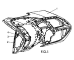
- Figure 1 shows a schematic perspective view of the front panel of an automobile which is assembled by means of a side fixing system on respective columns 2 of the framework of structure of the vehicle.
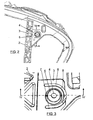
- the panel 1 incorporates in each one of its sides a support area 3 provided with a hole 4, the hole of which is made inside a draw 5, as can best be observed in Figures 2 and 3 .
- Outside of this draw area 3 has two through grooves 6 and 7, one located on each side of the draw 5, in a direction approximately perpendicular to the bar 2 of the framework of the vehicle.
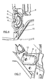
- This channel 8 is defined as can best be observed in Figure 4 by a reduction in thickness of the plate forming the support area 3.
- a flange 9 having a hole 10 opposing hole 4 of area 3 projects from the bar 2.
- This hole 10 as can best be observed in Figure 5 can also be surrounded by a draw which is coupled exteriorly to the draw 5 of area 3.
- the support area 3 can further have a recess 11 in which the flange 9 is coupled as shown in Figures 5 and 6 .
- the two side fixing areas forming the structure of the invention serve to enlarge the range of tolerances, i.e. to compensate for the possible dispersions that may occur during manufacture. All of this is achieved as a result of the through grooves 6 and 7, therefore the draw 5 with its hole 4 is not connected to the panel along its entire perimeter, but rather they are only connected in two areas, one defined by the channel 8 and the other opposite one, with the entire thickness of the support area 3.
- Connecting area 3 and flange 9 can be carried out by means of a screw or a clamp introduced through the corresponding opposing holes 4 and 10, although other connecting elements can be used. With any type of connection which is used the function of the side fixing areas is the same since it is the side absorbing the dispersions.
- the fixing structure of the invention is integrated in the sides of panel and is formed by side flanges which are responsible for enlarging the range of available tolerances.
Landscapes
- Engineering & Computer Science (AREA)
- Chemical & Material Sciences (AREA)
- Combustion & Propulsion (AREA)
- Transportation (AREA)
- Mechanical Engineering (AREA)
- Connection Of Plates (AREA)
- Body Structure For Vehicles (AREA)
Abstract
Description
- The present invention relates to an anchoring structure for the front-end panel of automobiles which is formed on each side of the panel by a bar belonging to the framework of the automobile on which there is supported an area of the panel which is fixed to the bar by means of screws or other connecting elements.
- Currently the anchoring between the panel and the framework of the automobile is carried out by means of a flat connection that can have different types of configurations, but which in all its variants has to adjust to very precise dispersions and tolerances, since the tolerance interval is very limited due to the fact that the parts are smooth. During the assembly dispersions occur making the panel unable to be correctly positioned. These dispersions translate into an increase in time and in manufacturing and assembly costs, since the panel must be made with care in order to fulfill the tolerance requirements. The small dispersion range available implies using a certain amount of time in verifying the assembly by means of gages or other devices.
- The object of the present invention is to eliminate the problems set forth by means of an assembly structure which allows achieving a correct positioning and centering of the instrument panel with respect to the framework of the automobile. To that end the panel is fixed to the framework by means of side connections incorporating flanges and formations which allow absorbing the dispersions which can occur in the manufacturing of the panel, thus facilitating and simplifying the assembly thereof.
- The structure of the invention comprises on each end of the panel a bar belonging to the framework of the automobile, from which a flange projects on which there is supported an especially configured area of the panel. Both the flanges and the support areas of the panel have opposing holes for passing the connecting elements which can consist of screws, clamps, etc.
- Each support area of the panel has two through grooves which are located one on each side of the hole having diametrically opposite positions, these grooves being directed in a direction approximately perpendicular to the bar of the framework of the automobile. Running between these two grooves on the side opposite to the side occupied by the bar of the framework of the automobile, there is a bent channel which is concentric with the hole of the support area. This channel is defined by a reduction in thickness of the area of the panel.
- The hole of the support area of the panel is preferably surrounded by a draw after which the grooves and the mentioned channel are located.
- With the mentioned arrangement, the support areas of the panel are defined by the mentioned cavities which, upon being surrounded by the grooves and channel described, offer a certain absorption capacity which will allow enlarging the range of tolerances, since the possible possibilities that may occur during the manufacture and which can be reflected during the operation of assembling the panel can be compensated.
- The hole of the flange projecting from the bar of the framework of the automobile can also be surrounded by a draw which can be coupled on the draw encircling the hole of the corresponding support area of the panel.
- According to another feature of the invention the support area of the panel has a recess which will have an outline approximately identical to that of the flange to allow coupling said flange on the support area of the panel, thus achieving a simple coupling between the assembly and connecting elements located on each side of the panel.
- The invention offers a side fixing structure of the panel solving the traditional dispersion problems which were presented in traditional solutions.
- The element allowing the advantages indicated is integrated in the sides of the panel and is formed by the mentioned support areas with the draw surrounding the fixing holes and grooves and channel and surrounding such holes.
- The arrangement of the structure of the invention is shown in the attached drawings in an embodiment is shown, given by way of a non-limiting example and with the aid of which a more detailed explanation of the invention will be made.
- In the drawings:
-
Figure 1 is a schematic perspective view of the panel assembled with the structure of the invention. -
Figure 2 is a front elevational view of one of the sides of the panel with the assembly structure of the invention. -
Figure 3 shows in detail the support area of the panel in one of the sides -
Figure 4 is a horizontal sectional view of the support area of the panel taken according to the section line 4-IV ofFigure 3 . -
Figure 5 is a vertical sectional view of the anchoring structure of the invention taken according to the section line 5-V ofFigure 2 . -
Figure 6 is a perspective view of the section ofFigure 5 . -
Figure 7 is an inner side view of one of the side fixings of the panel. -
Figure 1 shows a schematic perspective view of the front panel of an automobile which is assembled by means of a side fixing system onrespective columns 2 of the framework of structure of the vehicle. The panel 1 incorporates in each one of its sides asupport area 3 provided with ahole 4, the hole of which is made inside adraw 5, as can best be observed inFigures 2 and 3 . Outside of thisdraw area 3 has two throughgrooves draw 5, in a direction approximately perpendicular to thebar 2 of the framework of the vehicle. Running between these grooves on the side to opposite the side occupied by thebar 2, there is abent channel 8 which is approximately concentric with thehole 4. Thischannel 8 is defined as can best be observed inFigure 4 by a reduction in thickness of the plate forming thesupport area 3. - In turn as can best be observed in
Figure 7 , aflange 9 having ahole 10 opposinghole 4 ofarea 3 projects from thebar 2. Thishole 10 as can best be observed inFigure 5 can also be surrounded by a draw which is coupled exteriorly to thedraw 5 ofarea 3. - The
support area 3 can further have arecess 11 in which theflange 9 is coupled as shown inFigures 5 and6 . - The two side fixing areas forming the structure of the invention serve to enlarge the range of tolerances, i.e. to compensate for the possible dispersions that may occur during manufacture. All of this is achieved as a result of the through
grooves draw 5 with itshole 4 is not connected to the panel along its entire perimeter, but rather they are only connected in two areas, one defined by thechannel 8 and the other opposite one, with the entire thickness of thesupport area 3. - Connecting
area 3 andflange 9 can be carried out by means of a screw or a clamp introduced through the correspondingopposing holes - Upon increasing the dispersion range, it is possible to reduce the times and the costs of manufacturing the panel 1 since the verification process is considerably reduced and the manufacturing can be carried out with less precision. With all this, fixing the panel solves the dispersion problems that traditional fixing systems have.
- The fixing structure of the invention is integrated in the sides of panel and is formed by side flanges which are responsible for enlarging the range of available tolerances.
Claims (4)
- An anchoring structure for anchoring the front-end panel of automobiles, comprising on each side a bar (2) belonging to the framework of the automobile, from which there projects a flange (9) on which there is supported an area (3) of the panel (1), said flange (9) and area (3) having respective opposing holes (4) and (10) for passing the connecting elements; each support area (3) of the panel (1) having two through grooves (6) and (7) one located on each side of the hole, in a direction perpendicular to the mentioned bar (2), running between the end of the grooves (6) and (7) on the side opposite to the side occupied by said bar (2), there is a bent channel (8) concentric with the hole (4) which is defined by a reduction in thickness of the area of the panel (1).
- A structure according to claim 1, characterized in that the hole (4) of the support area (3) of the panel (1) is surrounded by a draw (5) after which the mentioned channel (8) and grooves (6) and (7) are located.
- A structure according to claim 2, characterized in that the hole (10) of the flange (9) is surrounded by a draw which can be coupled on the draw surrounding the hole (4) of the corresponding support area (3) of the panel (1).
- A structure according to the previous claims, characterized in that the support area (3) of the panel (1) has a recess (11) on which the flange (9) of the bar (2) of the framework of the automobile is coupled.
Applications Claiming Priority (1)
| Application Number | Priority Date | Filing Date | Title |
|---|---|---|---|
| ES200602807U ES1064494Y (en) | 2006-12-28 | 2006-12-28 | ANCHORAGE STRUCTURE FOR THE CAR FRONT BOARD |
Publications (3)
| Publication Number | Publication Date |
|---|---|
| EP1939074A2 true EP1939074A2 (en) | 2008-07-02 |
| EP1939074A3 EP1939074A3 (en) | 2009-02-25 |
| EP1939074B1 EP1939074B1 (en) | 2011-02-16 |
Family
ID=38293867
Family Applications (1)
| Application Number | Title | Priority Date | Filing Date |
|---|---|---|---|
| EP20070380380 Not-in-force EP1939074B1 (en) | 2006-12-28 | 2007-12-27 | Anchoring structure for anchoring the dashboard panel of automobiles |
Country Status (3)
| Country | Link |
|---|---|
| EP (1) | EP1939074B1 (en) |
| DE (1) | DE602007012513D1 (en) |
| ES (2) | ES1064494Y (en) |
Cited By (2)
| Publication number | Priority date | Publication date | Assignee | Title |
|---|---|---|---|---|
| WO2014006287A1 (en) * | 2012-07-06 | 2014-01-09 | Peugeot Citroen Automobiles Sa | Soundproof windshield opening lower cross member |
| EP3219586A1 (en) | 2016-03-15 | 2017-09-20 | PSA Automobiles SA | Arrangement for keeping a dashboard of a motor vehicle in position and motor vehicle comprising such an arrangement |
Family Cites Families (3)
| Publication number | Priority date | Publication date | Assignee | Title |
|---|---|---|---|---|
| JP4286503B2 (en) * | 2002-08-09 | 2009-07-01 | 日産自動車株式会社 | Mounting clip and mounting structure using the mounting clip |
| FR2862268B1 (en) * | 2003-11-17 | 2008-10-17 | Faurecia Interieur Ind | DASHBOARD WITH MOBILE LOWER PART IN THE EVENT OF SHOCK AND CORRESPONDING MOTOR VEHICLE |
| JP2005289112A (en) * | 2004-03-31 | 2005-10-20 | Honda Motor Co Ltd | Instrument panel structure of vehicle |
-
2006
- 2006-12-28 ES ES200602807U patent/ES1064494Y/en not_active Expired - Fee Related
-
2007
- 2007-12-27 DE DE200760012513 patent/DE602007012513D1/en active Active
- 2007-12-27 ES ES07380380T patent/ES2360306T3/en active Active
- 2007-12-27 EP EP20070380380 patent/EP1939074B1/en not_active Not-in-force
Non-Patent Citations (1)
| Title |
|---|
| None |
Cited By (5)
| Publication number | Priority date | Publication date | Assignee | Title |
|---|---|---|---|---|
| WO2014006287A1 (en) * | 2012-07-06 | 2014-01-09 | Peugeot Citroen Automobiles Sa | Soundproof windshield opening lower cross member |
| FR2992940A1 (en) * | 2012-07-06 | 2014-01-10 | Peugeot Citroen Automobiles Sa | LOWER WINDSHIELD BAY TRAILER, SEALED TO NOISE. |
| CN104718126A (en) * | 2012-07-06 | 2015-06-17 | 标致·雪铁龙汽车公司 | Window opening lower cross member for acoustic windshield |
| CN104718126B (en) * | 2012-07-06 | 2016-12-14 | 标致·雪铁龙汽车公司 | Window opening lower cross member for acoustic windshield |
| EP3219586A1 (en) | 2016-03-15 | 2017-09-20 | PSA Automobiles SA | Arrangement for keeping a dashboard of a motor vehicle in position and motor vehicle comprising such an arrangement |
Also Published As
| Publication number | Publication date |
|---|---|
| ES1064494U (en) | 2007-03-16 |
| ES2360306T3 (en) | 2011-06-02 |
| DE602007012513D1 (en) | 2011-03-31 |
| EP1939074B1 (en) | 2011-02-16 |
| ES1064494Y (en) | 2007-06-16 |
| EP1939074A3 (en) | 2009-02-25 |
Similar Documents
| Publication | Publication Date | Title |
|---|---|---|
| CN101312853A (en) | Mounting device for fastening systems for car body finishing elements | |
| EP2906871B1 (en) | Light module with two or more reflectors for a motor vehicle | |
| CN111240023B (en) | AR connection device, AR glasses device and AR glasses assembly method | |
| EP4204769B1 (en) | Flow meter | |
| CN109789813B (en) | Adjustment device for a vehicle seat and method for assembling the adjustment device | |
| ES2373320T3 (en) | FIXING PROVISION OF A WINDSHIELD WIPER INSTALLATION. | |
| US20160033808A1 (en) | Back frame and liquid display device with the same | |
| EP1939074B1 (en) | Anchoring structure for anchoring the dashboard panel of automobiles | |
| JP3967970B2 (en) | Mirror device for vehicle | |
| US7338192B2 (en) | Headlight fixing device | |
| CN102256865B (en) | Vehicle front end assembly and method | |
| US9566955B2 (en) | Length-adjustable telescopic tube, support jack and assembly process | |
| CN105370132A (en) | Window lifter assembly with different fixing points for a guide rail | |
| CN113276762B (en) | Devices for fastening lighting strips to motor vehicles | |
| CN100435181C (en) | Display panel installation structure | |
| JP2006513081A (en) | Arrangement structure for connecting a tubular first component to a second component and a method for manufacturing such an arrangement structure | |
| CN101146698A (en) | Injection-molded part, energy-absorbing assembly with spacers, and method for manufacturing such an assembly | |
| US7475930B2 (en) | Interior components of motor vehicles | |
| CN101709854A (en) | Installation and positioning structure of automobile lamp | |
| CN104052190B (en) | The manufacturing method and driving unit of the driving unit of motor vehicle servo drive | |
| CN101297461A (en) | electric motor with fixed adapter | |
| CN220549016U (en) | T-Box subassembly and vehicle | |
| CN113446290A (en) | Fixing member and connecting member | |
| KR102253810B1 (en) | inspecting apparatus for head lining of vehicle | |
| CN205890771U (en) | Mounting structure of tolerance absorbing structure , screw thread mounting structure and vehicle decorative board |
Legal Events
| Date | Code | Title | Description |
|---|---|---|---|
| PUAI | Public reference made under article 153(3) epc to a published international application that has entered the european phase |
Free format text: ORIGINAL CODE: 0009012 |
|
| AK | Designated contracting states |
Kind code of ref document: A2 Designated state(s): AT BE BG CH CY CZ DE DK EE ES FI FR GB GR HU IE IS IT LI LT LU LV MC MT NL PL PT RO SE SI SK TR |
|
| AX | Request for extension of the european patent |
Extension state: AL BA HR MK RS |
|
| PUAL | Search report despatched |
Free format text: ORIGINAL CODE: 0009013 |
|
| AK | Designated contracting states |
Kind code of ref document: A3 Designated state(s): AT BE BG CH CY CZ DE DK EE ES FI FR GB GR HU IE IS IT LI LT LU LV MC MT NL PL PT RO SE SI SK TR |
|
| AX | Request for extension of the european patent |
Extension state: AL BA HR MK RS |
|
| 17P | Request for examination filed |
Effective date: 20090727 |
|
| AKX | Designation fees paid |
Designated state(s): DE ES FR GB IT |
|
| GRAP | Despatch of communication of intention to grant a patent |
Free format text: ORIGINAL CODE: EPIDOSNIGR1 |
|
| GRAS | Grant fee paid |
Free format text: ORIGINAL CODE: EPIDOSNIGR3 |
|
| GRAA | (expected) grant |
Free format text: ORIGINAL CODE: 0009210 |
|
| AK | Designated contracting states |
Kind code of ref document: B1 Designated state(s): DE ES FR GB IT |
|
| REG | Reference to a national code |
Ref country code: GB Ref legal event code: FG4D |
|
| REF | Corresponds to: |
Ref document number: 602007012513 Country of ref document: DE Date of ref document: 20110331 Kind code of ref document: P |
|
| REG | Reference to a national code |
Ref country code: DE Ref legal event code: R096 Ref document number: 602007012513 Country of ref document: DE Effective date: 20110331 |
|
| REG | Reference to a national code |
Ref country code: ES Ref legal event code: FG2A Ref document number: 2360306 Country of ref document: ES Kind code of ref document: T3 Effective date: 20110602 |
|
| PLBE | No opposition filed within time limit |
Free format text: ORIGINAL CODE: 0009261 |
|
| STAA | Information on the status of an ep patent application or granted ep patent |
Free format text: STATUS: NO OPPOSITION FILED WITHIN TIME LIMIT |
|
| 26N | No opposition filed |
Effective date: 20111117 |
|
| REG | Reference to a national code |
Ref country code: DE Ref legal event code: R097 Ref document number: 602007012513 Country of ref document: DE Effective date: 20111117 |
|
| PGFP | Annual fee paid to national office [announced via postgrant information from national office to epo] |
Ref country code: IT Payment date: 20121220 Year of fee payment: 6 |
|
| PGFP | Annual fee paid to national office [announced via postgrant information from national office to epo] |
Ref country code: GB Payment date: 20130102 Year of fee payment: 6 |
|
| GBPC | Gb: european patent ceased through non-payment of renewal fee |
Effective date: 20131227 |
|
| PG25 | Lapsed in a contracting state [announced via postgrant information from national office to epo] |
Ref country code: GB Free format text: LAPSE BECAUSE OF NON-PAYMENT OF DUE FEES Effective date: 20131227 |
|
| PG25 | Lapsed in a contracting state [announced via postgrant information from national office to epo] |
Ref country code: IT Free format text: LAPSE BECAUSE OF NON-PAYMENT OF DUE FEES Effective date: 20131231 |
|
| REG | Reference to a national code |
Ref country code: FR Ref legal event code: PLFP Year of fee payment: 9 |
|
| PG25 | Lapsed in a contracting state [announced via postgrant information from national office to epo] |
Ref country code: IT Free format text: LAPSE BECAUSE OF NON-PAYMENT OF DUE FEES Effective date: 20131227 |
|
| PGFP | Annual fee paid to national office [announced via postgrant information from national office to epo] |
Ref country code: DE Payment date: 20160302 Year of fee payment: 9 |
|
| REG | Reference to a national code |
Ref country code: FR Ref legal event code: PLFP Year of fee payment: 10 |
|
| REG | Reference to a national code |
Ref country code: DE Ref legal event code: R119 Ref document number: 602007012513 Country of ref document: DE |
|
| PG25 | Lapsed in a contracting state [announced via postgrant information from national office to epo] |
Ref country code: DE Free format text: LAPSE BECAUSE OF NON-PAYMENT OF DUE FEES Effective date: 20170701 |
|
| REG | Reference to a national code |
Ref country code: FR Ref legal event code: PLFP Year of fee payment: 11 |
|
| PGFP | Annual fee paid to national office [announced via postgrant information from national office to epo] |
Ref country code: FR Payment date: 20171229 Year of fee payment: 11 |
|
| PGFP | Annual fee paid to national office [announced via postgrant information from national office to epo] |
Ref country code: ES Payment date: 20180126 Year of fee payment: 11 |
|
| PG25 | Lapsed in a contracting state [announced via postgrant information from national office to epo] |
Ref country code: FR Free format text: LAPSE BECAUSE OF NON-PAYMENT OF DUE FEES Effective date: 20181231 |
|
| REG | Reference to a national code |
Ref country code: ES Ref legal event code: FD2A Effective date: 20200205 |
|
| PG25 | Lapsed in a contracting state [announced via postgrant information from national office to epo] |
Ref country code: ES Free format text: LAPSE BECAUSE OF NON-PAYMENT OF DUE FEES Effective date: 20181228 |