EP1938997A2 - Ink jet printer - Google Patents
Ink jet printer Download PDFInfo
- Publication number
- EP1938997A2 EP1938997A2 EP08004508A EP08004508A EP1938997A2 EP 1938997 A2 EP1938997 A2 EP 1938997A2 EP 08004508 A EP08004508 A EP 08004508A EP 08004508 A EP08004508 A EP 08004508A EP 1938997 A2 EP1938997 A2 EP 1938997A2
- Authority
- EP
- European Patent Office
- Prior art keywords
- ink
- holes
- recording head
- portions
- jet printer
- Prior art date
- Legal status (The legal status is an assumption and is not a legal conclusion. Google has not performed a legal analysis and makes no representation as to the accuracy of the status listed.)
- Granted
Links
- 239000000976 ink Substances 0.000 claims description 611
- 238000007789 sealing Methods 0.000 claims description 71
- 238000003491 array Methods 0.000 claims description 19
- 230000007423 decrease Effects 0.000 claims description 3
- 238000013459 approach Methods 0.000 claims 2
- 238000013016 damping Methods 0.000 description 110
- 241001247986 Calotropis procera Species 0.000 description 44
- 239000000758 substrate Substances 0.000 description 43
- 230000003014 reinforcing effect Effects 0.000 description 33
- 239000012528 membrane Substances 0.000 description 30
- 239000007788 liquid Substances 0.000 description 15
- 239000003566 sealing material Substances 0.000 description 9
- 239000000853 adhesive Substances 0.000 description 7
- 230000001070 adhesive effect Effects 0.000 description 7
- 238000004891 communication Methods 0.000 description 5
- 238000010276 construction Methods 0.000 description 4
- 238000012423 maintenance Methods 0.000 description 4
- 238000004519 manufacturing process Methods 0.000 description 4
- 238000007665 sagging Methods 0.000 description 4
- 229920003002 synthetic resin Polymers 0.000 description 4
- 239000000057 synthetic resin Substances 0.000 description 4
- 239000012298 atmosphere Substances 0.000 description 3
- 229910052751 metal Inorganic materials 0.000 description 3
- 239000002184 metal Substances 0.000 description 3
- 238000009736 wetting Methods 0.000 description 3
- 230000002411 adverse Effects 0.000 description 2
- 239000003990 capacitor Substances 0.000 description 2
- 238000007599 discharging Methods 0.000 description 2
- 230000002452 interceptive effect Effects 0.000 description 2
- 239000000463 material Substances 0.000 description 2
- 239000005871 repellent Substances 0.000 description 2
- 239000011347 resin Substances 0.000 description 2
- 229920005989 resin Polymers 0.000 description 2
- 229910000838 Al alloy Inorganic materials 0.000 description 1
- 229910000990 Ni alloy Inorganic materials 0.000 description 1
- 229910000831 Steel Inorganic materials 0.000 description 1
- 238000005452 bending Methods 0.000 description 1
- 239000003795 chemical substances by application Substances 0.000 description 1
- 238000004140 cleaning Methods 0.000 description 1
- 230000003247 decreasing effect Effects 0.000 description 1
- 238000006073 displacement reaction Methods 0.000 description 1
- 239000013013 elastic material Substances 0.000 description 1
- 239000012530 fluid Substances 0.000 description 1
- 238000001746 injection moulding Methods 0.000 description 1
- 238000000034 method Methods 0.000 description 1
- 238000012856 packing Methods 0.000 description 1
- 238000005192 partition Methods 0.000 description 1
- 230000002093 peripheral effect Effects 0.000 description 1
- 229920001721 polyimide Polymers 0.000 description 1
- 239000009719 polyimide resin Substances 0.000 description 1
- 239000010935 stainless steel Substances 0.000 description 1
- 229910001220 stainless steel Inorganic materials 0.000 description 1
- 239000010959 steel Substances 0.000 description 1
- 238000003466 welding Methods 0.000 description 1
Images











Classifications
-
- B—PERFORMING OPERATIONS; TRANSPORTING
- B41—PRINTING; LINING MACHINES; TYPEWRITERS; STAMPS
- B41J—TYPEWRITERS; SELECTIVE PRINTING MECHANISMS, i.e. MECHANISMS PRINTING OTHERWISE THAN FROM A FORME; CORRECTION OF TYPOGRAPHICAL ERRORS
- B41J2/00—Typewriters or selective printing mechanisms characterised by the printing or marking process for which they are designed
- B41J2/005—Typewriters or selective printing mechanisms characterised by the printing or marking process for which they are designed characterised by bringing liquid or particles selectively into contact with a printing material
- B41J2/01—Ink jet
- B41J2/17—Ink jet characterised by ink handling
- B41J2/175—Ink supply systems ; Circuit parts therefor
- B41J2/17503—Ink cartridges
- B41J2/1752—Mounting within the printer
- B41J2/17523—Ink connection
Definitions
- the present invention relates to an ink jet printer and particularly to such an ink jet printer in which ink is supplied from an ink storing tank via an ink supply tube to a recording head mounted on a movable head holder.
- Japanese Patent Publication No. 7-121583 discloses a tube-supply-type ink jet printer including a housing; an ink storing tank detachably attached to the housing; a flexible ink supply tube; a movable carriage; and a recording head which is mounted on the carriage and to which ink is supplied from the ink storing tank via the ink supply tube.
- the ink jet printer when the above-indicated ink jet printer is checked for maintenance and, for example, the recording head is replaced with a new one, or when the ink supply tube is temporarily detached from a tube joint on the carriage during an assembling operation in a factory, the ink may leak from the ink supply tube and fall onto the carriage. If the carriage is moved, in a recording operation, with the ink remaining on the carriage, the ink may be moved because of inertia and accordingly the recording head may be wetted by the ink and fail to perform the recording operation. More specifically described, the ink may wet an adhered portion or portions of the recording head and lower the adhering force, or may wet an electronic component or components such as a flexible flat cable and cause an electric short circuit.
- connection portion where an ink supply tube is connected and accordingly ink may leak is located remote from a portion where a recording head is mounted, then the recording head is effectively prevented from being adversely affected by the ink that may leak from an end of the ink supply tube.
- one or more portions e.g., an adhered portion or an electronic component
- the claimable modes include at least respective modes corresponding to the appended claims, but may additionally include broader or narrower modes of the present invention or even one or more different inventions than the present invention.
- Each of the following modes (1) through (11) is numbered like the appended claims, and depends from the other mode or modes, where appropriate, so as to help understand the claimable modes and to indicate and clarify possible combinations of elements or technical features thereof. It is, however, to be understood that the present invention is not limited to the elements or technical features of the following modes, or the combinations thereof, that will be described below for illustrative purposes only.
- An ink jet printer comprising:
- the ink-contact preventing portion prevents the ink from wetting the recording head.
- the present ink jet printer can prevent the ink from damaging the function of the recording head.
- An ink jet printer comprising:
- connection portion where the ink supply tube is connected to the ink delivering tank and accordingly the ink may leak is located remote from the main portion of the head holder that holds the recording head. Therefore, even if the ink may leak, the ink does not wet the holding portion of the head holder. In addition, even if the ink that has leaked may be moved toward the holding portion, the ink would dry up before the ink reaches the main portion. Eventually, the recording head is effectively prevented from being wetted by the ink. Thus, when the ink may leak from the connection portion where the ink supply tube is connected to the ink delivering tank, the present ink jet printer can prevent the ink from damaging the function of the recording head.
- An ink jet printer comprising:
- connection portion where the ink supply tube is connected to the ink delivering tank is provided in the first extension portion of the ink delivering tank that is located outside the second main portion of the head holder that holds the recording head.
- the connection portion where the ink may leak is located remote from the recording head. Therefore, even if the ink may leak from the connection portion where the ink supply tube is connected to the ink delivering tank, the present ink jet printer can effectively prevent the ink from wetting the recording head.
- An ink jet printer comprising:
- the ink-movement preventing portion may include a surrounding wall or groove which fully or partly surrounds the opening of the bottom wall, or may include a surrounding portion which fully or partly surrounds the opening and is coated with an ink-repellent or water-repellent agent.
- the ink-movement preventing portion may either completely or incompletely (i.e., partly) prevent the ink from moving into the opening.
- the ink-movement preventing portion prevents the ink from moving into the opening formed through the thickness of the bottom wall of the head holder. Therefore, even if a small amount of ink may flow into the head holder, the ink can hardly enter the opening.
- portions or elements e.g., an adhered portion or an electronic component
- portions or elements susceptible to ink
- the adhered portion can be prevented from being wetted by the ink, and the lowering of the adhering force can be avoided.
- an electronic component such as a flexible flat cable is provided under the opening, the electronic component can be prevented from being wetted by the ink, and the occurrence of an electric short circuit can be avoided.
- An ink jet printer comprising:
- the projecting wall fully or partly surrounds the opening formed through the thickness of the bottom wall of the head holder. Therefore, even if the ink that has leaked may flow into the head holder, the wall can prevent the ink from entering the opening. Since the wall can be easily provided around the opening, the ink can be easily prevented from entering the opening. Thus, if portions or elements (e.g., an adhered portion or an electronic component) susceptible to ink are provided under the bottom wall, those portions or elements can be prevented from being wetted by the ink.
- portions or elements e.g., an adhered portion or an electronic component
- An ink jet printer comprising:
- the ink flow outlets of the ink delivering tanks and/or (b) the ink flow inlets of the recording head are sounded by the double ribs, and the sealing portions of the elastic member fit in the spaces provided between the double ribs.
- the sealing portions of the elastic member can be effectively prevented from coming off the double ribs or tilting outward.
- the ink jet printer can enjoy a high degree of liquid tightness around the ink flow outlets of the ink delivering tanks and the ink flow inlets of the recording head.
- a sealing structure comprising:
- each of the two outer first annular projections includes the outer portion which is located outside a corresponding one of the two outer through-holes, extends along the corresponding outer through-hole, and has, at the substantially middle portion thereof, the first thickness greater than the second thickness of another portion of the each outer first annular projection. Therefore, the outer portion cannot be easily tilted outward. Thus, even if, when the first annular projections are compressed, the compressing forces may be applied to the outer portion in a direction to tilt it outward, the outer portion of the each outer first annular projection can prevent the leakage of the fluid.
- a sealing structure comprising:
- the inner circumferential surface of each of the through-holes is kept substantially continuous with the inner circumferential surface of a corresponding one of the flow outlets and with the inner circumferential surface of a corresponding one of the flow inlets and, in this state, both the first and second annular projections are compressed.
- the through-holes can enjoy a high degree of liquid tightness.
- each of the second annular projections may press the corresponding first annular projections in directions to tilt them toward the corresponding through-holes, when the first and second annular projections are compressed.
- one or more of the first annular projections includes an outer portion which is opposite to the inner portion thereof adjacent to another of the first annular projections in the first direction, and which has the first thickness greater than the second thickness of the inner portion, the tilting of the outer portion can be prevented, and the inner circumferential surface of each of the through-holes is kept substantially continuous with the inner circumferential surface of a corresponding one of the flow outlets and with the inner circumferential surface of a corresponding one of the flow inlets.
- the through-holes can enjoy a high degree of liquid tightness.
- An ink jet printer comprising:
- the first and second connection portions are connected to each other owing to the elastic force of the spring member.
- the connecting device can enjoy a simple construction, and the time needed to manufacture the connecting device can be shortened.
- An ink jet printer comprising:
- the cable supporting portion supports the electric cable such that the cable extends through the space between the flexible membrane and the electric-circuit substrate, without contacting the upper surface of the flexible membrane.
- the operation or displacement of the flexible membrane to damp the fluctuations of pressure of the ink is not restrained by the electric cable.
- the flexible membrane and the cable are prevented from being damaged.
- An ink jet printer comprising:
- the electronic component is connected to the electric circuit such that the component projects from the electric-circuit substrate and is located in the vicinity of the ink delivering tank, and the electric cable electrically connects the actuator of the recording head to the electric circuit, while extending through the first space between the ink delivering tank and the electronic component and the second space between the ink delivering tank and the electric-circuit substrate.
- the recording head, the ink delivering tank, the circuit substrate, and the electronic component can be provided in a small space and accordingly those elements as a whole can be reduced in size.
- the electric cable can be provided in the small space, without interfering with those elements.
- Two or more of the above-described second through eleventh modes (2) through (11) may be arbitrarily combined with each other, i.e., may be embodied on a single ink jet printer.
- all of the modes (2) through (11) may be combined altogether and embodied on a single ink jet printer.
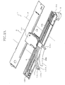
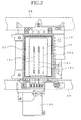
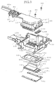
- FIGs. 1A , 2 , and 3 show an ink jet printer 1 as a first embodiment of the present invention.
- the ink jet printer 1 includes a recording head 11, a head holder 12, a damping device 14, and a reinforcing frame 33.
- the head holder 12 holds the recording head 11 and supports the damping device 14, and also functions as a movable carriage.
- the head holder 12 as the carriage holds the recording head 11, and is movable relative to a recording sheet P as a sort of recording medium.
- the recording head 11 is of an ink jet type wherein a droplet of ink is ejected from each of ink ejection nozzles 16a, 16b, 16c, 16d, and has a plate-like shape.
- the head holder 12 is formed of a synthetic resin, and supports the damping device 14.
- Four sorts of inks are supplied from four ink storing tanks, not shown, respectively, via respective ink supply tubes 13a, 13b, 13c, 13d, to the damping device 14, and are reserved by the same 14. Then, the four inks are delivered from the damping device 14 to the recording head 11.
- the ink storing tanks are detachably attached to a tank supporter, not shown, provided in a housing, not shown, of the printer 1 (the housing is a stationary frame of the printer 1), and each of the ink storing tanks stores a large amount of ink to be supplied to the recording head 11.
- the present ink jet printer 1 prints or records a full-color image and, to this end, the four ink storing tanks store black, cyan, magenta, and yellow inks, respectively.
- the head holder 12 as the carriage is slideably supported by a front and a rear guide member 2A, 2B that are provided in a front and a rear portion of the housing such that the two guide members 2A, 2B extend in a lengthwise direction of the housing.
- the front guide member 2A has a generally L-shaped cross section taken along a plane perpendicular to a direction of sliding or moving of the head holder 12; and the rear guide member 2B has a horizontal surface extending in the direction of sliding or moving of the head holder 12.
- the head holder 12 is connected to a portion of an endless timing belt 4 that is wound on a drive and a driven pulley 3A, 3B.
- the head holder 12 When the drive pulley 3A is rotated by an electric motor 5 and the timing belt 4 is moved, the head holder 12 is reciprocated on the two guide members 2A, 2B in the lengthwise direction of the housing. An upper end of the head holder 12 is covered by a cover member 24.
- a sheet feeding device not shown, feeds the recording sheet P, below the recording head 11, in a direction, A, perpendicular to the direction of movement of the head holder 12, in such a manner that a full-color image is recorded on the recording sheet P by the recording head 11.
- the present ink jet printer 1 additionally includes an ink collecting portion, not shown, for collecting the inks that are periodically ejected or flushed by the recording head 11 to prevent clogging of the nozzles 16a through 16d, during a recording operation of the head 11; and a maintenance unit, not shown, for performing a cleaning operation to clean a nozzle-support surface of the recording head 11, a recovering operation to suck selectively each sort of ink from the head 11, and a removing operation to remove air bubbles (or air) from the damping device 14.
- the recording head 11 includes a cavity unit 17 that has, in one end portion thereof, four ink flow inlets 18a, 18b, 18c, 18d that correspond to the four inks, respectively, are arranged in an array, and open in an upper surface of the unit 17.
- the four inks are supplied from the four ink flow inlets 18a through 18d via respective ink supply channels, not shown, to the four groups of ink ejection nozzles 16a through 16d, respectively.
- the recording head 11 additionally includes a piezoelectric actuator 19 that drives or operates the cavity unit 17 to eject, from each of the nozzles 16a through 16d, a droplet of ink. As shown in Fig.
- an area of the upper opening of the ink flow inlet 18a corresponding to the black ink (BK) is larger than that of the upper opening of each of the other ink flow inlets 18b, 18c, 18d corresponding to the cyan, magenta, and yellow inks (C, M, Y), respectively.
- a plan-view contour of the piezoelectric actuator 19 is smaller than that of the cavity unit 17 and, when the actuator 19 is stacked on a back or upper surface of the cavity unit 17, an outer peripheral portion of the upper surface of the cavity unit 17 that surrounds the actuator 19 and includes the respective upper openings of the ink flow inlets 18a through 18d remains exposed as a portion of a back or upper surface of the recording head 11.
- a flexible flat cable 20 that applies an electric voltage to the piezoelectric actuator 19 is fixed, at one end portion thereof, to an upper surface of the actuator 19, and a driver IC (integrated circuit) 21 is electrically connected to the cable 20.
- the cable 20 is electrically connected to an electric- circuit substrate 22 ( Fig. 5 ) that is provided above the damping device 14.
- the circuit substrate 22 is connected via another flexible flat cable 20a to another electric-circuit substrate, not shown, that is provided in the housing. Since the driver IC 21 generates heat, a heat sink 23 ( Fig. 7 ) formed of an aluminum alloy is held in contact with the driver IC 21, so that the IC 21 cools down owing to the heat sink 23.
- the damping device 14 includes, as a main portion thereof, a case unit 25 whose inner space is separated by partition walls into a plurality of damping chambers 31a, 31b, 31c, 31d as ink delivering tanks that correspond to the black ink (BK), the cyan ink (C), the magenta ink (M), and the yellow ink (Y), respectively.
- BK black ink
- C cyan ink
- M magenta ink
- Y yellow ink
- the case unit 25 of the damping device 14 includes a box-like lower case 26 that opens upward; and an upper case 27 that is fixed to the lower case 26 while covering the upper opening of the same 26.
- the lower and upper cases 26, 27 are each formed, by injection molding, of a synthetic resin, and are liquid-tightly fixed to each other by, e.g., supersonic welding.
- the above-indicated four damping chambers 31a through 31d are defined.
- Each of the damping chambers 31a through 31d may be constituted by a single room, or alternatively two or more rooms that communicate with each other via one or more flow passages.
- the four damping chambers 31a through 31d communicate with four ink flow outlets 32a, 32b, 32c, 32d, respectively.
- the heat holder 12 includes a bottom wall 12a to a lower surface of which the recording head 11 is adhered such that the back or upper surface of the head 11 extends substantially parallel to the bottom wall 12a.
- the damping device 14 that temporarily stores the four inks, and an air-discharging-valve device 15 that discharges air bubbles (i.e., air) collected by the damping chambers 31a through 31d of the damping device 14.
- the recording head 11 has, in the lower surface thereof, the two arrays of nozzles 16a corresponding to the black ink (BK), the array of nozzles 16b corresponding to the cyan ink (C), the array of nozzles 16c corresponding to the magenta ink (M), and the array of nozzles 16d corresponding to the yellow ink (Y), in the order of description, in a direction from the left to the right in the figure.
- the arrays of nozzles 16a through 16d extend in a direction perpendicular to the direction of movement of the head holder 12 as the carriage, and each of the nozzles 16a through 16d opens downward to face an upper surface of the recording sheet P.
- the four ink flow outlets 32a through 32d of the damping device 14 are arranged in an array in a lower surface of the lower case 26, such that each of the flow outlets 32a through 32d opens downward at a height position lower than the bottom wall 12a of the head holder 12.
- the cavity unit 17 of the recording head 11 has, in the upper surface thereof, the four ink flow inlets 18a through 18d that communicate with respective one ends of the ink supply channels (or manifolds), not shown, corresponding to the four inks, respectively.
- the four ink flow inlets 18a through 18d of the cavity unit 17 are aligned with the four ink flow outlets 32a through 32d of the damping device 14, respectively, such that the four flow outlets 32a through 32d communicate with the four flow inlets 18a through 18d via four ink flow holes 33b, 33c, 33d, 33e of the reinforcing frame 33, respectively, and an elastic sealing member 34 such as a rubber packing member.
- the recording head 11 is fixed to the bottom wall 12a of the head holder 12 in such a manner that the reinforcing frame 33 is provided between the back or upper surface of the head 11 and the lower surface of the bottom wall 12a.
- the reinforcing frame 33 has a flat thin shape extending along the upper surface of the recording head 11, and has a central opening 33a that is somewhat larger than the outer contour of the piezoelectric actuator 19 and somewhat smaller than the outer contour of the cavity unit 17.
- the reinforcing frame 33 is fixed, by adhesion, to the back or upper surface of the cavity unit 17, such that the actuator 19 and the flexible flat cable 20 are located in the central opening 33a of the frame 33.
- the reinforcing frame 33 is made of metal (e.g., stainless steel SUS430 according to Japanese Industrial Standard), and is thicker and more rigid than the cavity unit 17.
- the reinforcing frame 33 has, in one end portion thereof corresponding to the ink flow inlets 18a through 18d of the cavity unit 17, the four ink flow holes 33b through 33e that are arranged in the array and connect between the four ink flow outlets 32a through 32d of the damping device 14 and the four ink flow inlets 18a through 18d of the cavity unit 17.
- a protection cover 51 having a generally U-shaped configuration in its plan view is attached to the reinforcing frame 33 such that the protection cover 51 surrounds the recording head 11 and thereby fills a space left between the recording head 11 and the head holder 12.
- the case unit 25 of the damping device 14 includes an extension portion 27a that laterally extends from one end portion of the upper case 27 that is opposite to another end portion thereof corresponding to the ink flow outlets 32a through 32d.
- the extension portion 27a has four inner ink flow passages 29a, 29b, 29c, 29d, and four outer ink flow passages 35a, 35b, 35c, 35d, that correspond to the four inks, i.e., the black ink (BK), the cyan ink (C), the magenta ink (M), and the yellow ink (Y), respectively.
- the four inner ink flow passages 29a through 29d are independent of each other and communicate, at respective downstream-side ends thereof, with the four damping chambers 31a through 31d, respectively, and communicate, at respective upstream-side ends thereof, with the four outer ink flow passages 35a through 35d, respectively, that are also independent of each other.
- the four outer ink flow passages 35a through 35d are defined by closing, with a first flexible membrane 52, four grooves formed in a lower surface of the extension portion 27a; and the four inner ink flow passages 29a through 29d are defined by closing, with a second flexible membrane 54, four grooves formed in an upper surface of the extension portion 27a.
- the four outer ink flow passages 35a through 35d and the four inner ink flow passages 29a through 29d communicate with each other via four communication holes 53, respectively.
- the second flexible membrane 54 is extended to an area above four air-discharge passages 41, described later, so as to define the same 41.
- the four outer ink flow passages 35a through 35d communicate, at respective upstream- side ends thereof, with four ink inlet ports 55a, 55b, 55c, 55d that open in an upper surface 27c of an end portion 55 of the extension portion 27a of the damping device 14 (or the upper case 27 thereof).
- a tube joint 36 is provided on the upper surface of the end portion 55 of the extension portion 27a via an elastic sealing member 56 provided therebetween.
- the four ink inlet ports 55a through 55d of the extension portion 27a communicate with four ink outlet ports 30a, 30b, 30c, 30d of the tube joint 36 via four ink flow holes 56a, 56b, 56c, 56d of the sealing member 56, respectively.
- the head holder 12 includes an extension portion 12b that corresponds to, and is located below, the extension portion 27a of the upper case 27 of the damping device 14.
- the extension portion 12b of the head holder 12 extends laterally from an upper end portion of a holder case 12c as a main portion of the head holder 12 that supports or accommodates the damping device 14.
- a spring member 37 is used to attach, with an elastic force, the tube joint 36 having the four ink outlet ports 30a through 30d, to the respective extension portions 27a, 12b of the damping device 14 and the head holder 12.
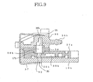
- the tube joint 36 includes four tube connection portions 36a, 36b, 36c, 36d where the four ink supply tubes 13a through 13d are connected to the four outer ink flow passages 35a through 35d and the four inner ink flow passages 29a through 29d that communicate with the four damping chambers 31a through 31d of the damping device 14, and is provided on the end portion 55 of the extension portion 27a of the damping device 14 that is remote from the holder case 12c as the main portion of the head holder 12 that holds the recording head 11.
- the tube joint 36 including the tube connection portions 36a through 36d is provided outside the main portion 12c of the head holder 12 that holds the recording head 11.
- the extension portion 12b of the head holder 12 has, on an upper surface thereof, a first ink dam 12i as a projecting wall that prevents, when droplets of ink fall on the extension portion 12b, the ink from moving toward the holder case 12c of the head holder 12.
- the extension portion 27a of the damping device 14 has, on a lower surface thereof, an elongate wall 27b as a projecting wall that is located at a position nearer to the holder case 12c than the first ink dam 12i, extends along the first ink dam 12i, and prevents the ink from moving toward the holder case 12c.
- the extension portion 12b of the head holder 12 has, on the upper surface thereof, a second ink dam 12j as a projecting wall that is located at a position nearer to the holder case 12c than the elongate wall 27b, extends along the elongate wall 27b, and prevents the ink from moving toward the holder case 12c.
- the two ink dams 12i, 12j and the elongate wall 27b cooperate with each other to define a maze that prevents or restrains a smooth flow of the ink toward the holder case 12c of the head holder 12.
- the second ink dam 12j is formed such that two opposite end portions of the second dam 12j are integral with two opposite side walls of the extension portion 12b of the head holder 12.
- the second ink dam 12j can substantially completely prevent the movement of the ink from the extension portion 12b toward the holder case 12c.
- the first and second ink dams 12i, 12j may be replaced with an ink trapping groove 12m that extends over an entire distance between the two opposite side walls of the extension portion 12b of the head holder 12.
- the elongate wall 27b of the extension portion 27a of the damping device 14 extends into the ink trapping groove 12m, such that an appropriate space is left between outer surfaces of the wall 27b and inner surfaces of the groove 12k.
- the ink trapping groove 12m and the elongate wall 27b can substantially completely prevent the movement of the ink from the extension portion 12b toward the holder case 12c.
- the dams and wall 12i, 12j, 27b and/or the groove 12m cooperate with each other to provide an ink-movement preventing portion that prevents the movement of the ink toward the holder case 12c of the head holder 12.
- the tube joint 36 includes the four tube connection portions 36a through 36d, and has the four ink outlet ports 30a through 30d.
- the four ink supply tubes 13a through 13d that communicate, at respective one ends thereof, with the above-described four ink tanks, respectively, are detachably connected, at the respective other ends thereof, to the four tube connection portions 36a through 36d, respectively.
- the two extension portions 12b, 27a are provided below the tube connection portions 36a through 36d to which the ink supply tubes 13a through 13d are connected and from which the inks may leak.
- the head holder 12 and the damping device 14 may be modified such that only one of the two extension portions 12b, 27a receives the inks leaking from the tube connection portions 36a through 36d and/or the ink supply tubes 13a through 13d.
- the tube joint 36 additionally includes, as an integral portion thereof, a guide portion 36e that guides the flexible flat cable 20a that connects the first electric- circuit board 22 provided on the head holder 12, to the second electric-circuit board, not shown, provided in the housing.
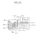
- the recording head 11 is provided below the bottom wall 12a of the holder case 12c of the head holder 12, and the bottom wall 12a has a plurality of rectangular openings 12d, and an elongate opening or a slit 12e, and additionally has a plurality of surrounding walls 12f, 12g each of which entirely or partially surrounds a corresponding one of the openings or slit 12d, 12e, so as to prevent the inks from entering the openings or slit 12d, 12e.
- each of the surrounding walls 12f, 12g provides an ink-entering preventing portion which prevents the ink from entering a corresponding one of the openings or slit 12d, 12e.
- the rectangular openings 12d are each filled with an adhesive S to fix, by adhesion, the upper surface of the recording head 11 to the lower surface of the bottom wall 12a of the head holder 12.
- the slit 12e is used to allow the flexible flat cable 20 to extend through the bottom wall 12a so as to be electrically connected to the piezoelectric actuator 19 of the recording head 11. Since each of the surrounding walls 12f, 12g prevents the inks from entering a corresponding one of the openings 12d, the adhesive S that is chemically weak to the components of the inks is not wetted by the inks, and accordingly the adhesive force of the adhesive S is not lowered. In addition, since respective portions of the flexible flat cable 20 and the piezoelectric actuator 19 that are electrically connected to each other are not wetted by the inks, an electric short circuit does not occur.
- the bottom wall 12a of the head holder 12 has the rectangular openings 12d, such that the rectangular openings 12d are arranged in two arrays along two long sides of the recording head 11, respectively.
- One 12g of the surrounding walls 12f, 12g is provided between one array of rectangular openings 12d and the slit 12e, and prevents the inks from moving into each of the slit 12e and the rectangular openings 12d of the one array.
- the surrounding walls 12f, 12g enjoy a simple construction.
- the slit 12e as the opening of the bottom wall 12a is entirely surrounded by the surrounding walls 12f, 12g, and a flat portion 12h ( Fig. 12 ) is located between the slit 12e and the walls 12f, 12g.
- a space left between the flexible flat cable 20 and the slit 12e is filled with a sealing material F that fixes the cable 20 to the bottom wall 12a and additionally prevents the inks from moving downward to the underside of the bottom wall 12a. Since the inks are effectively prevented from moving downward to the underside of the bottom wall 12a, the recording head 11 is reliably avoided from being wetted by the inks.
- the upper case 27 of the case unit 25 of the damping device 14 has, in the upper surface thereof, four grooves whose upper open ends are closed by the second flexible membrane 54 to define the four air-discharge passages 41 that correspond to the four inks, respectively, are independent of each other, and communicate, at respective one ends thereof, with respective upper portions of the four damping chambers 31a through 31d.
- the four air-discharge passages 41 extend across the case unit 25, and communicate, at the respective other ends thereof, respective upper ends of four air-discharge holes 42 that correspond to the four inks, respectively, and are formed through a thickness of the lower case 26.
- the reinforcing frame 33 has, in two corners thereof, two screw holes 33f, 33g, respectively, and the damping device 14 includes two attaching portions 14a that correspond to the two screw holes 33f, 33g, respectively, and have respective attaching holes 14b.
- Two screws 28 as fastening members are screwed into the two screw holes 33f, 33g via the two attaching holes 14b, respectively, so that the damping device 14 is fixed to the upper surface of the reinforcing frame 33 that is fixed to the lower surface of the bottom wall 12a of the head holder 12.
- each of the four air-discharge holes 42 accommodates a valve member 44 such that the valve member 44 is movable in the each air-discharge hole 42 so as to cause the each hole 42 to communicate with the atmosphere or shut off the each hole 42 from the atmosphere.
- the valve member 44 includes a large-diameter portion 44a, a small-diameter valve rod 44b integrally extending downward from a lower end of the large-diameter portion 44a, and a sealing portion 44c that fits on the valve rod 44b such that the sealing portion 44c is held in contact with the lower surface of the large-diameter portion 44a.
- Each air-discharge hole 42 has, in an axially intermediate portion thereof, a communication port 42a that is closed and opened by the large-diameter portion 44a of the valve member 44.
- Each air-discharge hole 42 additionally accommodates a spring member 45 that biases the valve member 44 in a direction in which the large-diameter portion 44a closes the communication port 42a.
- the valve member 44 is normally pressed in a downward direction by the spring member 45, so that the communication port 42 is closed by the large-diameter portion 44a via the sealing portion 44c and accordingly the air discharging valve is closed.
- the respective valve rods 44b of the four valve members 44 are pushed upward by four projecting bars of a maintenance unit, not shown, so that the respective large-diameter portions 44a and respective sealing portions 44c of the four valve members 44 are moved away from the respective communication ports 42a of the corresponding air-discharge holes 42 and accordingly the four air discharging valves are opened.
- a suction pump not shown, is driven or operated to suck concurrently the air (or air bubbles) collected by the four damping chambers 31a through 31d of the damping device 14 and discharge the sucked air into the atmosphere.
- the four inks are supplied from the four ink storing tanks to the recording head 11 via the four ink supply tubes 13a through 13d, the four inks are temporarily stored by the four damping chambers 31a through 31d provided between the four ink supply tubes 13a through 13d and the recording head 11, so that air bubbles naturally separate from the inks and move upward into the respective upper portions (i.e., air chambers) of the damping chambers 31a through 31d.
- the air (or air bubbles) collected by the damping chambers 31a through 31d can be discharged by the suction pump.
- the cavity unit 17 as part of the recording head 11 includes a nozzle sheet having the arrays of nozzles 16a through 16d; and a plurality of thin sheets that are provided on the nozzle sheet such that the thin sheets are stacked on, and adhered to, each other to define the ink supply channels communicating with the nozzles 16a through 16d.
- the nozzle sheet is made of a synthetic resin such as a polyimide resin, and the thin sheets are each formed of a nickel alloy steel sheet and have a thickness of from 50 ⁇ m to 150 ⁇ m.
- the nozzle sheet has the large number of nozzles 16 each of which has a small diameter of about 25 ⁇ m and which are arranged in the five arrays 16a through 16d ( Fig.
- the five arrays of nozzles 16a through 16d extend in the lengthwise direction of the nozzle sheet or the cavity unit 17, such that in the two arrays of nozzles 16a or the two arrays of nozzles 16b, 16c, the nozzles are arranged in a staggered or zigzag fashion.
- An entire lower surface of the sheet-type piezoelectric actuator 19 is pre-coated with an adhesive sheet 19a that is formed of an ink-impermeable synthetic resin as a sort of adhesive.
- This piezoelectric actuator 19 is fixed, by adhesion, to an upper surface of the cavity unit 17 such that the actuator 19 and the cavity unit 17 have an appropriate positional relationship.
- the flexible flat cable 20 is connected to the upper surface of the piezoelectric actuator 19, such that a large number of electric wirings of the cable 20 are electrically connected to a large number of electrodes of the actuator 19.
- Fig. 12 illustrates a manner in which the space left between the flexible flat cable 20 and the slit 12e is filled with the sealing material F. More specifically described, a lower end of a needle 71 such as a metal needle or a hard-resin needle is placed on the flat portion 12h located between the slit 12e and the surrounding walls 12f, 12g, and an intermediate portion of the needle 71 is supported on an upper end of the surrounding wall 12f.
- the flat portion 12h and the wall 12f function as guide portions for smoothly guiding the movements of the needle 71 to apply the sealing material F to the entire space left between the cable 20 and the slit 12e.
- the sealing material F can be stably applied using the needle 71, while the needle 71 is prevented from being inadvertently moved to even damage the cable 20.
- the sealing material F filling the slit 12e can prevent the inks from moving downward to the underside of the bottom wall 12a of the head holder 12 through the slit 12e.
- the inks might leak from the tube connection portions 36a through 36d where the ink supply tubes 13a through 13d have been attached. Since, however, the tube connection portions 36a through 36d are located, on the respective extension portions 27a, 12b of the damping device 14 and the head holder 12, at the respective positions remote from electronic components such as the piezoelectric actuator 19 of the recording head 11, the flexible flat cable 20 connected to the actuator 19, or the driver IC 21 connected to the cable 20, those electronic components are not wetted by the inks.
- the inks that have fallen onto the extension portion 12b of the head holder 12 are prevented by the ink dams 12i, 12j and the elongate wall 27b from moving toward the electronic components, even if the head holder 12 may be tilted such that the holder case 12c is positioned below the extension portion 12b.
- the surrounding walls 12f, 12g prevent the inks from entering the openings and slit 12d, 12e.
- the adhesive S and the sealing material F filling the openings and slit 12d, 12e are not wetted by the inks, and accordingly the respective portions of the piezoelectric actuator 19 and the flexible flat cable 20 that are electrically connected to each other are not wetted by the inks.
- the recording head 11 in particular, the electronic components thereof are freed of disorders such as an electric short circuit caused by the wetting thereof by the inks.
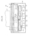
- Fig. 1B shows a second of the present invention that relates to an ink jet printer 100.
- two guide shafts 106, 107 are provided in an inner space of a housing 102 as a stationary frame of the printer 1, and cooperate with each other to support a head holder 109 that also functions as a movable carriage.
- the head holder 109 holds a recording head 130, and is attached to an endless belt 111 that is moved by an electric motor 110. When the motor 110 is driven or operated, the head holder 109 is moved on the guide shafts 106, 107.
- ink storing tanks 105a, 105b, 105c, 105d are detachably attached to a tank holder or supporter 103 fixed to the housing 102, and are connected to a damping device 140 supported by the head holder 109, via respective flexible ink supply tubes 114a, 114b, 114c, 114d.
- the four ink storing tanks 105a, 105b, 105c, 105d store a black ink (BK), a cyan ink (C), a magenta ink (M), and a yellow ink (Y), respectively.
- the head holder 109, the recording head 130, and the damping device 140 of the ink jet printer 100 as the second embodiment have respective constructions identical with those of the head holder 12, the recording head 11, and the damping device 14 of the ink jet printer 1 as the first embodiment, and accordingly the description of those elements 109, 130, 140 is omitted.
- the ink jet printer 1 as the first embodiment will be described in more detail by reference to Figs. 14 , 15A , 15B , 16 , 17 , 18A, 18B, and 18C .
- a surface of the recording head 11 from which the inks are ejected will be referred to as the lower surface thereof, and an opposite surface of the head 11 will be referred to as the upper surface thereof.
- a construction of a portion of the damping device 14 (or the lower case 26 thereof) that surrounds the four ink flow outlets 32a, 32b, 32c, 32d is described.
- a direction in which respective lower open ends of the four ink flow outlets 32a through 32d are arranged will be referred to as a first direction
- a direction perpendicular to the first direction will be referred to as a second direction
- a direction radially away from a center of the lower open end of each of the four ink flow outlets 32a through 32d will be referred to as the outward direction of the each ink flow outlet.
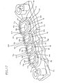
- the damping device 14 has, in the lower surface thereof, the generally elliptic, four ink flow outlets 32a through 32d that communicate with the four damping chambers 31a through 31d, respectively, and are arranged at a regular interval of distance in a single array such that respective major axes of the four outlets 32a through 32d extend parallel to each other.
- the respective lower open ends of the four ink flow outlets 32a through 32d are surrounded by respective inner ribs 61, 62, 63, 64 having respective elliptic shapes corresponding to the ink flow outlets 32a through 32d.
- the four inner ribs 61 through 64 project downward from the lower surface of the damping device 14. As shown in Fig.
- the first inner rib 61 includes two arcuate portions 61a, 61b which are opposed to the second direction and each of which is curved in the outward direction, and two straight portions 61c, 61d which are opposed to each other in the first direction.
- the second inner rib 62 includes two arcuate portions 62a, 62b which are opposed to the second direction and each of which is curved in the outward direction, and two straight portions 62c, 62d which are opposed to each other in the first direction;
- the third inner rib 63 includes two arcuate portions 63a, 63b which are opposed to the second direction and each of which is curved in the outward direction, and two straight portions 63c, 63d which are opposed to each other in the first direction;
- the fourth inner rib 64 includes two arcuate portions 64a, 64b which are opposed to the second direction and each of which is curved in the outward direction, and two straight portions 64c, 64d which are opposed to each other in the first direction.
- three pairs of adjacent straight portions i.e., the pair of straight portions 61d, 62c, the pair of straight portions 62d, 63c, and the pair of straight portions 63d, 64c are arranged at a regular interval of distance in the first direction, and define three straight inner grooves 81, 82, 83, respectively, therebetween.
- the lower open end of the first ink flow outlet 32a from which the black ink flows has an area larger than those of the respective lower open ends of the other ink flow outlets 32b, 32c, 32d from which the other inks flow, and accordingly the first inner rib 61 defines an opening having an area larger than those of respective openings of the other inner ribs 62, 63, 64 that are equal to each other in size.
- Respective outer surfaces of the four inner ribs 61 through 64 are surrounded by a single common outer rib 70 that is distant by a pre-determined distance from those outer surfaces and projects downward from the lower surface of the damping device 14. More specifically described, the outer rib 70 is formed such that the outer rib 70 is opposed to all the arcuate portions 61a, 61b, 62a, 62b, 63a, 63b, 64a, 64b and the two straight portions 61c, 64d, except for the six straight portions 61d, 62c, 62d, 63c, 63d, 64c, i.e., the above-described three pairs of adjacent straight portions.
- the lower open end of each of the four ink flow outlets 32a through 32d is surrounded by the double ribs 61 through 64, 70.
- the outer rib 70 includes two straight portions 71c, 74c that are distant in the outward direction from the respective straight portions 61c, 64d of the two inner ribs 61, 64 surrounding the respective lower open ends of the two ink flow outlets 32a, 32d located at respective opposite end positions in the first direction.
- the respective straight portions 61c, 64d of the two inner ribs 61, 64 are not adjacent to any of the other open ends.
- the two straight portions 71c, 74c generally extend in the second direction perpendicular to the first direction.
- the outer rib 70 includes eight arcuate portions 71a, 71b, 72a, 72b, 73a, 73b, 74a, 74b that are distant in the outward direction from the respective arcuate portions 61a, 61b, 62a, 62b, 63a, 63b, 64a, 64b of the four inner ribs 61 through 64 that generally extend in the first direction.
- the eight arcuate portions 71a, 71b, 72a, 72b, 73a, 73b, 74a, 74b and the two straight portions 71c, 74c of the outer rib 70 are formed such that the outer rib 70 has a single continuous shape in its plan view.
- the four inner ribs 61 through 64 cooperate with the outer rib 70 to define, therebetween, a single continuous outer groove 80 that is also continuous with the three straight inner grooves 81, 82, 83 defined by the three pairs of adjacent straight portions, i.e., the pair of straight portions 61d, 62c, the pair of straight portions 62d, 63c, and the pair of straight portions 63d, 64c.
- the elastic sealing member 34 e.g., a rubber bush fits in the grooves 80, 81, 82, 83.
- the rubber bush 34 has four through-holes 34a, 34b, 34c, 34c that communicate with the respective lower open ends of the four ink flow outlets 32a through 32d, and have respective inner surfaces whose shapes correspond to the respective shapes of respective outer surfaces of the four inner ribs 61 through 64.
- the four through-holes 34a through 34d are surrounded by eight arcuate sealing portions 46a, 46b, 47a, 47b, 48a, 48b, 49a, 49b and five straight sealing portions 46c, 49c, 45a, 45b, 45c, all of which projects from an upper surface of the rubber bush 34 and are continuous with each other.
- the eight arcuate sealing portions 46a, 46b, 47a, 47b, 48a, 48b, 49a, 49b cooperate with the two straight sealing portions 46c, 49c, located at the two opposite end positions, to have a shape corresponding to the shape of the outer groove 80 provided between the four inner ribs 61 through 64, and the outer rib 70, of the damping device 14.
- the three straight sealing portions 45a, 45b, 45c provided between the four through-holes 34a through 34d have respective shapes corresponding to the three straight inner grooves 81, 82, 83 provided between the three pairs of adjacent straight portions 61d, 62c, 62d, 63c, 63d, 64c of the four inner ribs 61 through 64.
- the rubber bush 34 includes four annular ribs 34e that project from a lower surface thereof that is to contact the reinforcing frame 33, and surround respective lower ends of the four through-holes 34a through 34d of the bush 34. In the state in which the rubber bush 34 contacts the reinforcing frame 33, the four annular ribs 34e surround the four ink flow holes 33a through 33d of the frame 33, independent of each other. A distance W between each pair of adjacent annular ribs 34e is smaller than a height H of the rubber bush 34.
- the rubber bush 34 additionally includes a projecting portion 34f that is provided in a lengthwise end portion of the bush 34. If a person grasps, with fingers, the projecting portion 34f, then the person can efficiently fit the rubber bush 34 in the grooves 80 through 83 or remove the bush 34 from the grooves 80 through 83.
- the rubber bush 34 is assembled with the damping device 14 and the recording head 11, in an assembling process described below.
- an upper surface 33h of the reinforcing member 33 is adhered to a lower surface 9p of the bottom wall 12a of the head holder 12.
- the recording head 11 is adhered, in advance, to a lower surface of the reinforcing frame 33.
- the rubber bush 34 is attached to the damping device 14, such that the sealing portions 46a, 46b, 47a, 47b, 48a, 48b, 49a, 49b, 46c, 49c, 45a, 45b, 45c of the bush 34 fit in the grooves 80, 81, 82, 83 formed between the inner ribs 61, 62, 63, 64 of the damper 14 and between the inner ribs 61 through 64 and the outer rib 70 of the damper 14.
- the damping device 14 is inserted, in a downward direction, into the head holder 12, such that the ink flow outlets 32a through 32d of the damper 14 are located in an opening 12q formed through the bottom wall 12a of the holder 12, and the two positioning pins 14c ( Fig. 16 ) projecting downward from two portions of the damping device 14, located on opposite sides of the array of ink flow outlets 32a through 32d, fit in two positioning holes of the reinforcing frame 33, respectively.
- the lower surface of the damping device 14 is opposed to the reinforcing frame 33, such that the through-holes 34a through 34d of the buffer bush 34 are aligned with the ink flow holes 33b through 33e of the frame 33, respectively.
- the two attaching screws 28 are inserted into the two attaching holes 14b, respectively, that are formed in the vicinity of the two positioning pins 14c of the damping device 14, and respective portions of the two screws 28 that project downward from the two holes 14b are screwed into the two screw holes 33f, 33g of the reinforcing frame 33, respectively.
- the damping device 14 and the recording head 11 cooperate with each other to apply a compressing force to the rubber bush 34, so that the bush 34 is compressed in a vertical direction. Consequently the two straight sealing portions 46c, 49c of the rubber bush 34 are caused to tilt in opposite outward directions, respectively, in the above-indicated first direction, and the four arcuate sealing portions 46a, 47a, 48a, 49a, and the four arcuate sealing portions 46b, 47b, 48b, 49b are caused to tilt in opposite outward directions in the second direction.
- the two straight sealing portions 46c, 49c of the rubber bush 34 that are respectively located at the opposite end portions thereof in the first direction, fit in the groove 80 formed between the double ribs, i.e., the respective straight portions 61c, 64c of the two inner ribs 61, 64 and the two straight portions 71c, 74c of the outer rib 70.
- the two straight sealing portions 46c, 49c are effectively prevented from tilting outward in the first direction.
- the eight arcuate sealing portions 46a, 46b, 47a, 47b, 48a, 48b, 49a, 49b of the rubber bush 34 also fit in the groove 80 formed between the double ribs, i.e., the respective arcuate portions 61a, 61b, 62a, 62b, 63a, 63b, 64a, 64b of the four inner ribs 61 through 64 and the eight arcuate portions 71a, 71b, 72a, 72b, 73a, 73b, 74a, 74b of the outer rib 70.
- the eight arcuate sealing portions 46a, 46b, 47a, 47b, 48a, 48b, 49a, 49b are effectively prevented from tilting outward in the second direction.
- each of the three straight sealing portions 45a, 45b, 45c of the rubber bush 34 fits in the three straight grooves 81, 82, 83, respectively, formed between the three pairs of adjacent straight portions 61d, 62c, 62d, 63c, 63d, 64c of the four inner ribs 61 through 64.
- each of the three straight sealing portions 45a, 45b, 45c is effectively prevented from tilting toward its adjacent ones of the through-holes 34a through 34d.
- each of the sealing portions 46a, 46b, 47a, 47b, 48a, 48b, 49a, 49b, 46c, 49c, 45a, 45b, 45c of the rubber bush 34 is compressed in the vertical direction, so that the each sealing portion is held in close contact with a corresponding one of the inner ribs 61 through 64, and the outer rib 70.
- each of the ring-like ribs (i.e., annular projections) 34e provided on the lower surface of the rubber bush 34 is compressed around a corresponding one of the ink flow holes 33b through 33e of the reinforcing frame 33, so that the each ring-like rib 34e is held in close contact with the frame 33.
- the four ink flow outlets 32a through 32d of the damping device 14 highly liquid-tightly communicate with the four ink flow holes 33b through 33e of the reinforcing frame 33.
- the respective lower open ends of the four ink flow outlets 32a through 32d of the damping device 14 are surrounded by the double ribs that are distant from each other in the respective outward directions of the lower open ends, i.e., the four individual inner ribs 61 through 64 and the single common outer rib 70.
- the sealing portions 45a, 45b, 45c, 46a, 46b, 46c, 47a, 47b, 48a, 48b, 49a, 49b, 49c of the rubber bush 34 fit in the grooves 80, 81, 82, 83 formed between the double ribs 61 through 64, 70, the sealing portions are effectively prevented from tilting in the outward directions of the lower open ends of the ink flow outlets 32a through 32d.
- the ink jet printer 1 can enjoy the high liquid tightness around the lower open ends of the ink flow outlets 32a through 32d of the damping device 14.
- the inner ribs 61 through 64 as part of the double ribs have the respective elliptic shapes surrounding the respective lower open ends of the ink flow outlets 32a through 32d, and the respective inner circumferential surfaces of the through-holes 34a through 34d of the rubber bush 34 fit on the respective outer surfaces of those elliptic inner ribs 61 through 64. Since the outer surface of each of the elliptic inner ribs 61 through 64 has a larger area than that of an outer surface of an inner rib that does not have a ring-like continuous shape, the inner circumferential surface of each of the through-holes 34a through 34d of the rubber bush 34 can contact the large outer surface of a corresponding one of the elliptic inner ribs 61 through 64. Thus, the ink jet printer 1 can enjoy the high liquid tightness around the lower open ends of the ink flow outlets 32a through 32d of the damping device 14.
- the portions of each one of the lower open ends of the ink flow outlets 32a through 32d which portions are not adjacent to the other open ends are surrounded by the double ribs, i.e., the portions 61a, 61b, 62a, 62b, 63a, 63b, 64a, 64b, 61c, 64d of the inner ribs 61 through 64 and the portions 71a, 71b, 72a, 72b, 73a, 73b, 74a, 74b, 71c, 74c of the outer rib 70.
- sealing portions 46a, 46b, 47a, 47b, 48a, 48b, 49a, 49b, 46c, 49c of the rubber bush 34 fit in the groove 80 between the above-indicated portions 61a, 61b, 62a, 62b, 63a, 63b, 64a, 64b, 61c, 64d of the inner ribs 61 through 64 and the above-indicated portions 71a, 71b, 72a, 72b, 73a, 73b, 74a, 74b, 71c, 74c of the outer rib 70, those sealing portions can be effectively prevented from tiling outward and accordingly the lowering of degree of liquid tightness around the lower open ends of the ink flow outlets 32a through 32d can be effectively prevented.
- the respective lower open ends of the first and fourth ink flow outlets 32a, 32d, located at the opposite end positions in the first direction, are protected by the double ribs, i.e., the respective straight portions 61c, 64d of the two inner ribs 61, 64 and the two straight portions 71c, 74c of the outer rib 70.
- the two pairs of straight portions 61c and 71c, 64d and 74c are located in the vicinity of the respective first portions of the above-indicated two lower open ends that are opposite, in the first direction, to the respective second portions thereof adjacent to the respective lower open ends of the second and third ink flow outlets 32b, 32c, such that the two pairs of straight portions extend in the second direction perpendicular to the first direction.
- sealing portions 46c, 49c of the rubber bush 34 fit in the groove 80 between the above-indicated portions 61c, 64d of the inner ribs 61, 64 and the above-indicated portions 71c, 74c of the outer rib 70, those sealing portions can be effectively prevented from tiling outward and accordingly the lowering of degree of liquid tightness around the lower open ends of the ink flow outlets 32a, 32d can be effectively prevented.
- the respective arcuate portions 61a, 61b, 62a, 62b, 63a, 63b, 64a, 64b of the four inner ribs 61 through 64 that extend generally in the first direction are protected by the respective arcuate portions 71a, 71b, 72a, 72b, 73a, 73b, 74a, 74b of the outer rib 70.
- sealing portions 46a, 46b, 47a, 47b, 48a, 48b, 49a, 49b of the rubber bush 34 fit in the groove 80 between the above-indicated portions 61a, 61b, 62a, 62b, 63a, 63b, 64a, 64b of the inner ribs 61 through 64 and the above-indicated arcuate portions 71a, 71b, 72a, 72b, 73a, 73b, 74a, 74b of the outer rib 70, those sealing portions can be effectively prevented from tiling outward and accordingly the lowering of degree of liquid tightness around the lower open ends of the ink flow outlets 32a through 32d can be effectively prevented.
- the outer rib 70 located outside the four inner ribs 61 through 64 surrounding the respective lower open ends of the four ink flow outlets 32a through 32d, continuously surrounds all the inner ribs 61 through 64. Since the sealing portions 36a, 36b, 47a, 47b, 48a, 48b, 49a, 49b, 46c, 49c of the rubber bush 34 fit in the continuous groove 80 formed between the four inner ribs 61 through 64 and the continuous outer rib 70, those sealing portions can be effectively prevented from tiling outward. Thus, the ink jet printer 1 can enjoy the high degree of liquid tightness around the respective lower open ends of the ink flow outlets 32a through 32d.
- a modified embodiment of the ink jet printer 1 will be described by reference to Fig. 19 .
- the same reference numerals as used in the embodiment shown in Figs. 17 and 18A are used to designate the corresponding elements or parts of the following two modified embodiments of the ink jet printer 1, and the description of those elements or parts is omitted.
- the single continuous outer rib 70 shown in Figs. 17 is replaced with a group of (i.e., ten) discontinuous outer ribs 200, 201, 202, 203, 204, 205, 206, 207, 208, 209.
- the group of outer ribs include a straight rib 200 that is located outside the straight portion 61c of the inner rib 61 and is opposed to the same 61c; two arcuate ribs 202, 203 that are located outside the two arcuate portions 61a, 61b of the inner rib 61, and are opposed to the same 61a, 61b, respectively; two arcuate ribs 204, 205 that are located outside the two arcuate portions 62a, 62b of the inner rib 62, and are opposed to the same 62a, 62b, respectively; two arcuate ribs 206, 207 that are located outside the two arcuate portions 63a, 63b of the inner rib 63, and are opposed to the same 63a, 63b, respectively; two arcuate ribs 208, 209 that are located outside the two arcuate portions 64a, 64b of the inner rib 64, and are opposed to the same 64a, 64b, respectively; and a straight rib
- the modified embodiment shown in Fig. 11 employs the ten outer ribs 200 through 209, and accordingly ten pairs of double ribs 61 through 64, 200 through 209, at only respective locations where the two end portions 46c, 49c of the bush 34 as seen in the first direction and the four pairs of end portions 46a, 46b, 47a, 47b, 48a, 48b, 49a, 49b of the bush 34 as seen in the second direction are located, so that those end portions of the bush 34 fit in respective grooves defined by the ten pairs of double ribs.
- all the end portions of the bush 34 as seen in the first and second directions can be effectively prevented from tilting outward.
- the modified embodiment shown in Fig. 19 differs from the ink jet printer 1 only in that the single continuously outer rib 70 of the printer 1 is replaced with the ten discontinuous outer ribs 200 through 209 in the modified embodiment, the modified embodiment can enjoy the same advantages as the above-described advantages of the ink jet printer 1.
- This modified embodiment employs a damping device 290 in place of the damping device 14 employed by the ink jet printer 1, and a recording head 300 substantially equivalent to two recording heads each of which is similar to the recording head 11 of the printer 1.
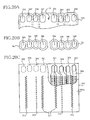
- the damping device 290 has, in a lower surface thereof, respective lower open ends of two ink flow outlets 291 from which a black ink (BK) flows and which belong to two groups of ink flow outlets, respectively; two ink flow outlets 292 from which a cyan ink (C) flows and which belong to the first group of ink flow outlets (i.e., the left-hand group in Fig. 20A ); two ink flow outlets 293 from which a magenta ink (M) flows and which belong to the second group of ink flow outlets (i.e., the right-hand group in Fig.
- the first group of ink flow outlets 291, 294, 292, 292 and the second group of ink flow outlets 291, 294, 293, 293 are symmetric with each other with respect to a middle point L1 between the two ink flow outlets 291. That is, if the first group of ink flow outlets 291, 294, 292, 292 are rotated by 180 degrees about the point L1, then the first group of ink flow outlets coincide with the second group of ink flow outlets 291, 294, 293, 293.
- the damping device 290 employed by this modified embodiment has, for each group of ink flow outlets, four inner ribs and a single outer rib that are respectively identical with the four inner ribs 61 through 64 and the single outer rib 70 of the damping device 14 of the ink jet printer 1, those inner and outer ribs are not shown in Fig. 20A , for easier understanding purposes only. Therefore, if the first group of inner and outer ribs for the first group of ink flow outlets 291, 294, 292, 292 are rotated by 180 degrees about the point L1, then the first group of inner and outer ribs coincide with the second group of inner and outer ribs for the second group of ink flow outlets 291, 294, 293, 293.
- the recording head 300 has, at respective positions corresponding to the eight ink flow outlets 291 through 294 of the damping device 14, two ink supply holes 301 corresponding to the black ink, two ink supply holes 302 corresponding to the cyan ink, two ink supply holes 303 corresponding to the magenta ink, and two ink supply holes 304 corresponding to the yellow ink.
- the recording head 300 has, in a nozzle-support surface 300a thereof, four central arrays of nozzles 311 corresponding to the black ink; two arrays of nozzles 314 corresponding to the yellow ink that are located on either side of the black-ink nozzles 311; two arrays of nozzles 312 corresponding to the cyan ink that are located outside one of the two arrays of nozzles 314; and two arrays of nozzles 313 corresponding to the magenta ink that are located outside the other array of nozzles 314.
- the four inks are supplied from the eight ink flow inlets 301 through 304 to the ten arrays of nozzles 311 through 314 via ten ink flow channels 306, respectively. As shown in Fig.
- each of the two ink flow inlets 291 corresponding to the black ink communicates with two ink flow channels 306; and each of the other, six ink flow inlets 292, 293, 294 corresponding to the cyan, magenta and yellow inks communicates with one ink flow channel 306.
- a rubber bush 34 shown in a left-hand half portion of Fig. 20B fits in grooves defined by the above-described first group of inner and outer ribs, not shown, formed around the left-hand group of ink flow outlets 291, 294, 292, and another rubber bush 34 shown in a right-hand half portion of Fig. 20B fits in grooves defined by the above-described second group of inner and outer ribs formed around the right-hand group of ink flow outlets 291, 294, 293.
- the two rubber bushes 34 have an identical shape and, if the left-hand rubber bush 34 is rotated by 180 degrees about an axis line perpendicular to the drawing sheet of Fig. 20B , then the left-hand bush 34 coincides with the right- hand bush 34.
- the ink jet printer 1 may be otherwise modified.
- the modified embodiment shown in Fig. 19 may be further modified by omitting the eight arcuate outer ribs 202 through 209, i.e., employing the two straight outer ribs 200, 201 only.
- this modified embodiment may be further modified by omitting the two straight outer ribs 200, 201 and employing the eight arcuate outer ribs 202 through 209 only.
- this modified embodiment may be further modified by omitting the four arcuate outer ribs 204, 205, 206, 207 and employing the two straight outer ribs 200, 201 and the other, four arcuate outer ribs 202, 203, 208, 209 only.
- the damping device 14 may be formed to have double ribs at only a location corresponding to the particular end portion of the rubber bush 34.
- the straight or arcuate outer ribs 200 through 209 may be replaced with a plurality of cylindrical ribs, triangle-pole ribs, square-pole ribs, or prismatic ribs that extend in the vertical direction. That is, the outer ribs 200 through 209 may be modified to have any shape so long as one or more end portions of the rubber bush 34 can be effectively prevented from tilting outward.
- each of the inner ribs 61 through 64 may be modified to have a different shape than the elliptic shape, such as a circular shape.
- the outer rib 70 or the outer ribs 200 through 209 may be modified to have a shape or shapes corresponding to the modified shapes of the inner ribs 61 through 64.
- each of the continuous inner ribs 61 through 64 may be replaced with a plurality of discontinuous portions arranged around the lower open end of a corresponding one of the ink flow outlets 32a through 32d.
- the rubber bush 34 employed by the ink jet printer 1 is replaced with an elastic member (e.g., a rubber bush) 450 shown in Figs. 21A, 21B , and 22C.
- an elastic member e.g., a rubber bush
- the elastic member 450 has four through-holes 451a, 451b, 451c, 451d that are arranged in an array in a first direction and communicate with the four ink flow inlets 18a, 18b, 18c, 18d of the recording head 11 (the cavity unit 17), respectively, and with the four ink flow outlets 32a, 32b, 32c, 32d of the damping device 14, respectively.
- the elastic member 450 is elongate in the first direction.
- Each of the through-holes 451a through 451d has a generally elliptic shape having a minor axis in the first direction and a major axis in a second direction perpendicular to the first direction.
- the ink flow outlet 32a from which the black ink (BK) flows has a larger area than those of the other ink flow outlets 32b, 32c, 32d
- the through-hole 451a through which the black ink flows has a larger area than those of the other through-holes 451b, 451c, 451d.
- the reinforcing frame 33 is provided on the upper surface of the recording head 11 and is integrated with the same 11, and accordingly the ink flow inlets 18a through 18d of the head 11 communicate with the ink flow holes 33b through 33e of the frame 33, respectively, the through-holes 451a through 451d of the elastic member 450 communicate with the ink flow inlets 18a through 18d of the recording head 11 via the ink flow holes 33b through 33e of the frame 33, respectively.
- the reinforcing frame 33 may be omitted.
- the elastic member 450 includes a flat base portion 455 that defines the through-holes 451a through 451d and extends on a plane perpendicular to respective axis lines B of the through-holes 451a through 451d.
- the elastic member 450 additionally includes four first annular projections (ring-like ribs) 456 that project, parallel to the axis lines B, from the base portion 455 toward the four ink flow inlets 18a through 18d, respectively, and surround the four through-holes 451a through 451d, respectively.
- first annular projections 456 surround the generally elliptic through-holes 451a through 451d arranged in the array in the first direction, the first annular projections 456 are arranged in an array in the first direction and each of the first annular projections 456 has a generally elliptic shape having a manor axis in the first direction and a major axis in the second direction.
- Each of two outer first annular projections 456 located at respective opposite ends of the array of first annular projections 456 in the first direction has, in the vicinity of the base portion 455, a variable thickness as measured in radial directions from the axis line B of a corresponding one of the two outer through-holes 451a, 451d.
- each of the two outer first projections 456 includes a thick portion 456a that has, in the vicinity of a substantially middle portion of an elongate inner surface 452 of the corresponding outer through-hole 451a, 451d, a thickness W1 greater than a thickness W2 of a remaining portion of the each of the two outer first projections 456 and the entirety of each of the other, two inner first projections 456 corresponding to the two inner through-holes 451b, 451c, as shown in Fig. 21B .
- the thick portion 456a of each of the two outer first projections 456 is effectively prevented from tilting outward in the first direction.
- each of the two outer first projections 456, and the entirety of each of the two inner first projections 456, that have the smaller thickness W2 include respective straight elongate portions that extend in the second direction and are adjacent to each other in the first direction, and respective pairs of arcuate short portions that extend in the first direction.
- the thick portion 456a of each of the two outer first projections 456 has, in the vicinity of the middle portion of the elongate inner surface 452 of the corresponding outer through- hole 451a, 451d, an inverted-triangular tapered cross section whose thickness gradually decreases in a direction away from the base portion 455 toward a tip of the thick portion 456a, as shown in Fig. 21A .
- the thick portion 456a has an increased thickness in the first direction, and is not easily tilted outward in the first direction.
- a distance L ( Fig. 21A ) in the first direction between the tip (ridge line) of each of the two thick portions 456a and the elongate inner surface 452 of the corresponding outer through-hole 451a, 451d gradually increases in a direction away from each of lengthwise opposite ends of the elongate inner surface 52 toward the middle portion of the same 52.
- the elongate inner surface 452 of each of the two outer through-holes 451a, 451d is substantially plane or flat, whereas the tip (ridge line) of the middle portion of each of the two thick portions 456a is curved outward in the first direction, as indicated at broken line in Fig. 21B .
- the outward tilting of the thick portion 456a can be effectively prevented.
- the four first annular projections 456 have the respective annular shapes suitable for surrounding the four through-holes 451a through 451d, independent of each other, and cooperate with each other to include three pairs of straight elongate portions each pair of which are adjacent to each other in the first direction and extend in the second direction, as shown in Figs. 21A and 21B .
- Each of two opposite end portions of the base portion 455 in the first direction that extend along the two outer through-holes 451a, 451d, respectively, in the second direction has a width W0 in the first direction, and a corresponding one of the two thick portions 456a extending along the respective elongate inner surfaces 52 of the two outer through-holes 451a, 451d is provided on the each end portion having the width W0, such that the one thick portion 456a is located or biased on the side of the corresponding outer through-hole 451a, 451d, i.e., a wide free space is left opposite to the through-hole 451a, 451d.
- a distance between the inner circumferential surface of each of the through-holes 451a through 451d and the outer circumferential surface (i.e., side surface) of the base portion 455 is substantially constant, i.e., substantially equal to the above-indicated width W0.
- a distance between each pair of through-holes adjacent to each other in the first direction i.e., the pair of through-holes 451a, 451b, the pair of through-holes 451b, 451c, and the pair of through-holes 451c, 451d, is substantially equal to the width W0.
- the degree of contacting of the base portion 455 with the inner and outer ribs 61 through 64, 70 of the damping device 14 is substantially constant or uniform with respect to the entire inner circumference of each of the through-holes 451a through 451d.
- the elastic member 450 additionally includes four second annular projections 457 that project, parallel to the respective axis lines B of the four through-holes 451a through 451d, from the base portion 455 toward the four ink flow outlets 32a through 32d, respectively, and surround the four through-holes 451a through 451d, respectively.
- the four second annular projections 457 are arranged in an array in the first direction.
- the sealing portions 45a, 45b, 45c, 46a, 46b, 46c, 47a, 47b, 48a, 48b, 49a, 49b, 49c shown in Fig. 18A the four second annular projections 457 are continuous with each other in the first direction.
- each pair of second annular projections 457 adjacent to each other in the first direction are integrated with each other at respective inner straight portions thereof located between the corresponding pair of adjacent through-holes 451a and 451b, 451b and 451c, or 451c and 451d, such that the integrated straight portion of the each pair of adjacent second projections 457 is located right above a middle position between the respective inner, parallel straight portions of the corresponding pair of adjacent first projections 456.
- two outer second annular projections 457 located at the respective opposite ends of the array of second annular projections 457 in the first direction include respective outer portions corresponding to the respective thick portions 356a of the two outer first annular projections 456, and each of those outer portions of the two outer second projections 457 is located on a substantially middle portion of a corresponding one of the respective opposite end portions of the base portion 455 in the first direction. More specifically described, each of the respective outer portions of the two outer second projections 457 projects from the upper surface of the base portion 455, while being spaced from a corresponding one of the two outer through-holes 451a, 451d and the outer circumferential (or side) surface of the base portion 455.
- the four second annular projections 457 fit in the three inner grooves 81, 82, 83 formed between the four inner ribs 61 through 64 and the single outer groove 80 that is formed between the inner ribs 61 through 64 and the outer rib 70 and is continuous with the inner grooves 81 through 83.
- the second projections 457 have a height greater than the depth of the grooves 80 through 83 and, in the state in which the elastic member 450 is assembled with, and sandwiched by, the damping device 14 and the reinforcing member 33, the bottom surface of the grooves 80 through 83 press the second projections 457 with a greater force than a force with which the inner and outer ribs 61 through 64, 70 press the base portion 455.
- the through- holes 451a through 451d of the elastic member 450 can be liquid-tightly sealed independent of each other.
- the elastic member 450 is assembled with the damping device 14 and the recording head 11 (or the reinforcing member 33), in the same manner as described above by reference to Fig. 14 .
- the elastic member 450 In the state in which the elastic member 450 is assembled with the damping device 14 and the recording head 11 (or the reinforcing member 33), the elastic member 450 is compressed in the vertical direction, i.e., the direction parallel to the respective axis lines B of the through-holes 451a through 451d, as shown in Fig. 21C . More specifically described, the inner and outer ribs 61 through 64, 70 are held in close contact with the upper surface of the base portion 455, and the respective lower portions of the four first annular projections 456 are elastically deformed or compressed.
- each of the four ink flow outlets 32a through 32d communicates with a corresponding one of the four ink flow inlets 18a through 18d, respectively, via a corresponding one of the four through-holes 151a through 151d and a corresponding one of the four ink flow holes 33b through 33e, respectively, such that respective inner circumferential surfaces of the each ink flow outlet, the one through-hole, the one flow hole, and the one ink flow inlet are substantially continuous with each other.
- connection portions where the ink flow outlets 32a through 32d, the through-holes 151a through 151d, the ink flow holes 33b through 33e, and the ink flow inlets 18a through 18d are connected to each other are free of stepped portions and accordingly air bubbles generated from the inks can be effectively prevented from being trapped in those stepped portions.
- each pair of first annular projections 456 adjacent to each other in the first direction include the respective inner straight portions that are located between the corresponding pair of adjacent through-holes 451a and 451b, 451b and 451c, or 451c and 451d and extend parallel to each other
- each pair of second annular projections 457 adjacent to each other in the first direction include the respective inner straight portions that are connected or integrated with each other and are located right above the middle position between the respective inner, parallel straight portions of the corresponding pair of adjacent first projections 456.
- the compressive force applied to the elastic member 450 is uniformly distributed to the four first projections 456, and accordingly the six inner parallel straight portions of the four first projections 456 can be compressed in a well-balanced manner without being tilted down. Therefore, the elastic member 450 can be held in close contact with the reinforcing member 33, and the degree of liquid tightness between the two members 450, 33 is highly improved.
- each of the respective thick portions 456a of the two outer first annular projections 456 is located at a position offset from the outer portion of the corresponding second annular projection 457, in the direction toward the corresponding one of the two outer through-holes 451a, 451d, as shown in Fig. 21A .
- each thick portion 456a might tilt in the direction toward the corresponding through-hole 451a or 451d.
- each thick portion 456a has the characteristic shape that can prevent itself from being tilted.
- the four second annular projections 457 are compressed between the damping device 14 and the base portion 455, such that the respective lower end surfaces of the inner and outer ribs 61 through 64, 70 that have a substantially same width are held in close contact with the upper surface of the base portion 455, inside and outside the entire circumference of each of the second annular projections 457.
- each of the second annular projections 457 can exhibit a high degree of liquid tightness.
- the elastic body 450 can be connected to the damping device 14 and the recording head 11 (or the reinforcing frame 33) with the high degree of liquid tightness and without leakage of the inks.
- the elastic member 450 has the first annular projections 456 on the lower surface of the base portion 455 that faces the ink flow inlets 18a through 18d of the recording head 11.
- the elastic member 450 may be modified to have the first annular projections 456 on the upper surface of the base portion 455 that faces the ink flow outlets 32a through 32d of the damping device 14, or on each of the upper and lower surfaces of the base portion 455.
- the sealing member 56 is formed of an elastic material such as rubber, and includes a flat base portion 56e and four cylindrical sealing portions 57a, 57b, 57c, 57d projecting upward and downward from the base portion 56e. Respective upper openings of the four sealing portions 57a through 57d are aligned with the four ink outlet ports 30a through 30b of the tube joint 36 as a first connection portion or member 85, respectively, and respective lower openings of the four sealing portions 57a through 57d are aligned with the four ink inlet ports 55a through 55d of the extension portion 27a (of the damping device 14) as a second connection portion or member 86, respectively.
- the tube joint 36 as the first connection portion, the extension portion 27a as the second connection portion, and the spring member 37, described in detail below, cooperate with each other to provide a connecting device that connects the ink supply tubes 13a through 13d to the damping device 14 functioning as the ink delivering tanks.
- the four ink outlet ports 30a through 30d of the first connection member 85 are enlarged to receive the respective upper end portions of the four sealing portions 57a through 57d, and the four ink inlet ports 55a through 55d of the second connection member 86 are enlarged to receive the respective lower end portions of the four sealing portions 57a through 57d.
- the spring member 37 is obtained by bending a metallic wire having an appropriate degree of elasticity. More specifically described, as shown in Fig. 10 , the spring member 37 includes two hook-like free end portions 91, 99; two upper horizontal arm portions 92, 98 that extend substantially horizontally from the two free end portions 91, 99, respectively; two vertical portions 93, 97 that are bent downward from the two upper horizontal arm portions 92, 98, respectively; two lower horizontal arm portions 94, 96 that extend substantially horizontally from respective lower ends of the two vertical portions 93, 97, respectively; and a connection portion 95 that connects between respective ends of the two lower horizontal arm portions 94, 96.
- the spring member 37 has a shape in which respective one ends of two generally U-shaped portions are connected to each other by a connection portion.
- the spring member 37 engages an upper surface of the tube joint 36 as the first connection member 85, respective side surfaces of the tube joint 36 and the extension portion 12b of the head holder 12, and a lower surface of the extension portion 12b.
- the two upper horizontal arm portions 92, 98 of the spring member 37 cooperate with each other to press downward the upper surface of the first connection member 85
- the two lower horizontal arm portions 94, 96 and the connection portion 95 of the spring member 37 cooperate with each other to press upward the lower surface of the extension portion 12b, so that the first and second connection members 85, 86 are kept connected to each other while being liquid-tightly sealed by the sealing member 56 sandwiched by the two connection members 85, 86.
- the tube joint 36 and the extension portion 12b are kept connected to each other.
- the first connection member 85 has, on a side surface 85a thereof, a pair of spring holding portions 38, 39 as engageable portions that are engageable with the two vertical portions 93, 97 of the spring member 37, respectively.
- the two spring holding portions 38, 39 include respective hook-like portions 38a, 39a that are spaced from the side surface 85a by respective gaps 38b, 39b that are opposed to each other along the side surface 85a.
- the two free end portions 91, 99, and the connection portion 95, of the spring member 37 are vertically aligned with a reference centerline which extends in a direction perpendicular to the drawing sheet of Fig. 9 and on which the four sealing portions 57a through 57d of the sealing member 56 are arranged.
- the two free end portions 91, 99 press downward respective portions of an upper surface 85b of a base portion of the first connection member 85 that are distant from each other along the reference centerline, and the connection portion 95 presses upward a linear portion of the lower surface of the extension portion 12b that extends along the reference centerline.
- the four tube connection portions 36a through 36d, and the four ink outlet ports 30a through 30d, of the tube joint 36 as the first connection member 85, and the four ink inlet ports 55a through 55d of the extension portion 27a as the second connection member 86 are located on respective planes that are perpendicular to the direction in which the spring member 37 pinches the two connection members 85, 86.
- the elastic force of the spring member 37 is uniformly applied to the four sealing portions 57a through 57d of the sealing member 56, so that the four tube connection portions 36a through 36d, the four ink outlet ports 30a through 30d, or the four ink inlet ports 55a through 55d are uniformly sealed by the four sealing portions 57a through 57d, respectively.
- the extension portion 12b of the head holder 12 extends parallel to the first and second connection members 85, 86.
- the second connection member 86 has, on a lower surface thereof, two projecting portions 86a, 86b that fit in two through- holes 12r, 12s that are vertically formed through a thickness of the extension portion 12b.
- the first connection member 85 has, on a lower surface thereof, four projecting portions, including a projecting portion 85c, which extend in four through-holes 58, respectively, that are vertically formed through a thickness of the flat base portion 56e of the sealing member 56, and two of which fit in two holes 59, 59, respectively, that open in an upper surface of the second connection member 86.
- the other projecting portions engages the upper surface of the second connection member 86 (i.e., the extension portion 27a), thereby keeping an appropriate distance between the first and second connection members 85, 86.
- the second connection member 86, the sealing member 56, and the first connection member 85 are stacked on the extension portion 12b.
- the spring member 37 pinches the tube joint 36 and the extension portion 12b.
- the first and second connection members 85, 86 are connected to each other with the sealing member 56 being interposed therebetween, and the tube joint 36 and the extension portion 12b are also connected to each other. That is, the three members, i.e., the first and second connection members 85, 86 and the extension portion 12b are connected to each other.
- the first and second connection members 85, 86 are connected to each other by the elastic force of the spring member 37.
- the tube joint 36 can enjoy a simple structure.
- a time needed to manufacture the printer 1 can be reduced.
- connection members 85, 86 Since the spring member 37 is detachably attached, the first and second connection members 85, 86 can be released from each other by just detaching the spring member 37 from those members 85, 86. Thus, the maintenance and replacement of the connection members 85, 86 can be easily carried out.
- the first connection member 85 includes the two spring holding portions 38, 39 as the engageble portions with which the spring member 37 is detachably engageable. That is, in the state in which the spring member 37 is engaged with the spring holding portions 38, 39, the spring member 37 can not naturally come off the first and second connection members 85, 85. In addition, since the spring holding portions 38, 39 can be used as indices in attaching the spring member 37 to those members 85, 86, the spring member 37 can be easily attached.
- the second connection member 86 can be produced as an integral portion of the damping device 14. Since the total number of steps needed to produce the second connection member 86 can be reduced as compared with a case where the second connection member 86 is produced separately from the damping device 14, the production cost of the ink jet printer 1 can be reduced.
- the head holder 12 includes the extension portion 12b that extends parallel to the first and second connection members 85, 86, and the spring member 37 pinches the two connection members 85, 86 and the extension portion 12b and thereby fixes the three members 85, 86, 12b to each other. Since the spring member 37 suffices for fixing the three members 85, 86, 12b, the fixing means for fixing the three members 85, 86, 12b can be simplified as compared with a case where a plurality of members are employed to fix the three members 85, 86, 12b, and additionally a time needed to fix those members 85, 86, 12b can be shortened.
- the four tube connection portions 36a through 36d, and the four ink outlet ports 30a through 30d, of the first connection member 85, and the four ink inlet ports 55a through 55d of the second connection member 86 are located on the respective planes that are perpendicular to the direction in which the spring member 37 pinches the two connection members 85, 86.
- the elastic force of the spring member 37 is uniformly applied to the four sealing portions 57a through 57d of the sealing member 56, so that the four tube connection portions 36a through 36d, the four ink outlet ports 30a through 30d, or the four ink inlet ports 55a through 55d are uniformly sealed by the four sealing portions 57a through 57d, respectively.
- the elastic force of the spring member 37 can be prevented from being locally lowered with respect to only one or two of the four sealing portions 57a through 57d and accordingly the liquid tightness of the sealing member 56 can be prevented from being locally lowered with respect to only the corresponding one or ones of the four ink outlet ports 30a through 30d or the four ink inlet ports 55a through 55d.
- Fig. 23 shows a modified embodiment of the ink jet printer 1, wherein a plurality of spring members 592 are employed in place of the spring member 37.
- the upper surface 85b of the first connection member 85 (the tube joint 36) is covered with a cover member 591.
- the cover member 591 has, in respective lower end portions of two side walls thereof, two engageable portions 591a that are engageable with two engageable portions of the extension portion 12b, respectively.
- the spring members 592 are provided between a lower surface 591b of the cover member 591 and the upper surface 85b of the first connection member 85.
- the spring members 592 are each constituted by, e.g., a sheet spring, and are arranged in the direction in which the four ink outlet ports 30a through 30d are arranged.
- each of the spring members 592 may be formed of any suitable material such as a metal wire, a sheet spring, or a resin, and may be formed to have any suitable shape.
- the single spring member 37 employed by the ink jet printer 1 may be replaced with a plurality of identical spring members 37 that cooperate with each other pinch the tube joint 36 and the extension portion 12b, at a plurality of pinching positions, respectively.
- each of the spring members 37 may be constituted by one that can apply only a considerably small elastic force at a corresponding one of the pinching positions.
- each of the spring members 37 can be attached, with a small force, to the tube joint 36 and the extension portion 12b, because the each spring member can apply only the considerably small elastic force.
- the spring member 37 may be modified to have three or more hook-like end portions that are similar to the hook- like end portions 91, 99.
- the modified spring member engages the upper surface 85b of the first connection member 85, at three or more positions, the modified spring member can press a wider area as compared with the spring member 37 having the two hook-like end portions 91, 99 only, and accordingly the elastic or pinching force of the modified spring member can be distributed to the wider area.
- the two vertical portions 93, 97 of the spring member 37 may be provided with respective fin members that project outward therefrom and can be grasped by fingers or a tool. In this case, even if the spring member 37 may be one that produces a great elastic force, the spring member 37 can be easily attached to pinch the tube joint 36 and the extension portion 12b.
- the spring holding portions 38, 39 may be provided on a side surface of either one of the second connection member 86 and the extension portion 12b.
- the spring member 37 may be used to pinch the first and second connection portions 85, 86 only.
- the respective lengths of the vertical portions 93, 97 of the spring member 37 can be changed depending upon the height (or thickness) of the tube joint 36, without taking the height (or thickness) of the extension portion 12b into account.
- Figs. 24 , 25 , 26 and 27A show a modified embodiment of the ink jet printer 1.
- the same reference numerals as used in the ink jet printer 1 are used to designate the corresponding elements and parts of the modified embodiment and the description thereof is omitted.
- an electric-circuit substrate 22 that is formed of a rigid material and supports one or more electric circuits. More specifically described, the circuit substrate 22 is supported by an upper end of a holder case 12c of the head holder 12, and is detachably attached, with a known attaching device (not shown), to the head holder 12. Between the circuit substrate 22 and the damping device 14, there is provided a horizontal space 14e. A cover member 24 is fixed to the head holder 12 so as to cover the circuit substrate 22.
- the electric circuits supported by the circuit substrate 22 includes electronic components 681, 682, 683 that project downward from a lower surface of the substrate 22 on one of opposite sides of the damping device 14 that is opposite to the air-discharging-valve device 15. More specifically described, as shown in Fig. 25 , the electronic components include a by-pass capacitor 681 that stores electric charges needed to drive an IC chip 21; a sheet detector 682 that detects a recording sheet P, i.e., judges whether the sheet P is present; and an encoder 683 that reads timing indices or marks provided on a belt-like timing- index member (not shown) fixed to the housing.
- the head holder 12 has two inner rooms 687, 688 that accommodate the sheet detector 682 and the by-pass capacitor 681, respectively, in a state in which the circuit substrate 22 is attached to the head holder 12.
- the piezoelectric actuator 19 of the recording head 11 is electrically connected to the circuit substrate 22 (i.e., the electric circuits supported thereby) by the flexible flat cable 20.
- the IC chip 21 is electrically connected to the cable 20.
- the IC chip 21 converts recording data in the form of serial data supplied from a main control device (not shown) fixed to the housing, into parallel data corresponding to the arrays of nozzles 16a through 16d, and additionally converts the parallel data into electric-voltage signals suitable to drive the piezoelectric actuator 19.
- the flexible flat cable 20 passes through the slit 12e formed through the bottom wall 12a of the head holder 12, and enters the inner space of the head holder 12.
- the cable 20 is further extended through a vertical space 14d provided between the heat sink 23 and the holder case 12c of the head holder 12 and the horizontal space 14e provided between the circuit substrate 22 and the damping device 14, is folded up around an end surface 22b of the substrate 22, and is detachably attached to a connector 685 provided on an upper surface 22c of the substrate 22. Since the cable 20 is provided in the above-described manner, the cable 20 does not contact any of the electronic components 681, 682, 683 provided on the lower surface of the circuit substrate 84.
- the heat sink 23 is fixed at a position near the slit 12e, and above the bottom wall 12a, of the head holder 12. As shown in Fig. 24 , the heat sink 23 includes a bottom portion 23a extending parallel to the bottom wall 12a, and a side portion 23b extending upward from the bottom portion 23a. An elastic member 686 formed of rubber presses the IC chip 21 against the bottom portion 23a, so that heat generated by the IC chip 21 can be conducted to the bottom portion 23a. Thus, the heat generated by the IC chip 21 can be efficiently radiated.
- the electric circuits (i.e., wiring patterns) supported by the circuit substrate 22 are connected, on one hand, to the connector 685 and the electronic components 681, 682, 683, and are connected, on the other hand, to the main control device via another flexible flat cable 20a.
- two ribs 650, 651 as cable supporting portions project upward from an upper end 27d of the upper case 27 of the damping device 14. More specifically descried, as shown in Figs. 26 and 27A , the two ribs 650, 651 first project horizontally from the upper end of the upper case 27 of the damping device 14 and then project upward into the horizontal space 14e between the circuit substrate 22 and the flexible membrane 54. Thus, the ribs 650, 651 are integral with the upper case 27 of the damping device 14.
- the two ribs 650, 651 project upward from the upper end 27d of the upper case 27 of the damping device 14, by a height H1.
- the height H1 is pre-determined such that even if the flexible flat cable 20 may sag downward, a lower surface of the cable 20 does not contact an upper surface of the flexible membrane 54.
- the height H1 is 1 mm. Since the two ribs 650, 651 are arranged in a widthwise direction of the cable 20 and cooperate with each other to support the lower surface of the cable 20, a distance of the two ribs 650, 651 is so pre-determined not to exceed the width of the cable 20.
- the lower surface 22a of the circuit substrate 22 is spaced from the flexible membrane 54 by a space having a height H2 greater than the height H1.
- the two ribs 650, 651 cooperate with each other to keep the lower surface of the flexible flat cable 20 above the upper surface of the flexible membrane 54, when the cable 20 extends through the horizontal space 14e between the circuit substrate 22 an the membrane 54. Thus, even if the cable 20 may sag downward, the lower surface of the cable 20 is prevented from contacting the upper surface of the membrane 54.
- the electronic components 681, 682, 683 are fixed to the circuit substrate 22 such that the components 681 through 683 project downward from the substrate 22 and are located on the laterally outer side of the damping device 14, and the flexible flat cable 20 extends from the piezoelectric actuator 19 to the circuit substrate 22 via the vertical space 14d between the damping device 14 and the electronic components 681 through 63 and the horizontal space 14e between the damping device 14 and the circuit substrate 22.
- the recording head 11, the damping device 14, the circuit substrate 22, and the electronic components 681 through 683 can be provided in a small space and accordingly those elements as a whole can be reduced in size.
- the cable 20 can be provided without interfering with any of those elements.
- the two ribs 650, 651 project upward from the upper end 27d of the upper case 27 of the damping device 14, into the horizontal space 14e between the circuit substrate 22 and the flexible membrane 54. Since the two ribs 650, 651 cooperate with each other to lift up the flexible flat cable 20 extending through the horizontal space 14e, the lower surface of the cable 20 can be prevented from sagging downward and contacting the upper surface of the membrane 54.
- the flexible membrane 54 is allowed to be displaced without being restrained or limited by the flexible flat cable 20, and accordingly the dynamic changes of respective pressures of the inks in the damping device 14 can be effectively absorbed by the membrane 54.
- the flexible membrane 54 and the flexible flat cable 20 can be prevented from being damaged.
- the damping device 14 has the two ribs 650, 651 that are spaced from each other in the widthwise direction of the flexible flat cable 20.
- the two ribs 650, 651 may be replaced with a single rib, not shown, that projects from the upper end 27d of the upper case 27 of the damping device 14, at a position corresponding to the widthwise middle position of the cable 20.
- the single rib can prevent the lower surface of the cable 20 from contacting the upper surface of the flexible membrane 54 even if the cable 20 may sag downward.
- the slit 12e may be surrounded by walls identical with the surrounding walls 12f, 12g shown in 7, and filled with a sealing material identical with the sealing material F.
- the two ribs 650, 651 may be replaced with a guide member 652 that is fixed to the lower surface 22a of the circuit substrate 22.
- the guide member 652 has a through-hole 652a that supports the flexible flat cable 20 by allowing the cable 20 to extend therethrough.
- the guide member 652 can prevent the cable 20 from contacting the flexible membrane 54.
- Two or more guide members 652 may be fixed to the lower surface 22a of the circuit substrate 22 such that the guide members 652 are spaced from each other in the direction in which the cable 20 extends in the horizontal space 14e. In this case, the guide members 652 cooperate with each other to support the cable 20 in a wider range and thereby more reliably prevent the cable 20 from sagging downward or contacting the membrane 54.
- the two ribs 650, 651 may be replaced with a pair of guide members 653, 654 that are fixed to the lower surface 22a of the circuit substrate 22 so as to be opposed to each other in the widthwise direction of the flexible flat cable 20 and are engaged with the widthwise opposite end portions of the cable 20, respectively.
- the two guide members 653, 654 cooperate with each other to support the cable 20 and thereby prevent the cable 20 from contacting the flexible membrane 54.
- Two or more pairs of guide members 653, 654 may be fixed to the circuit substrate 22 such that the pairs of guide members 653, 654 are spaced from each other in the direction in which the cable 20 extends in the horizontal space 14b.
- the pairs of guide members 653, 654 cooperate with each other to support the cable 20 in a wider range and thereby more reliably prevent the cable 20 from sagging downward or contacting the membrane 54.
- the two guide members 653, 654 may be fixed to the circuit substrate 22 such that the two guide members 653, 654 are not opposed to each other in the widthwise direction of the cable 20, i.e., are offset from each other in the direction in which the cable 20 extends. In this case, too, the two guide members 653, 654 cooperate with each other to support the cable 20 in a wider range and thereby prevent the cable 20 from sagging downward or contacting the membrane 54.
- Two or more support members may be selected from the above-described ribs 650, 651, the guide member 652, and the pair of guide members 653, 654, and may be used together with each other.
- the ribs 650, 651, the guide member 652, or the pair of guide members 653, 654 provide or provides a cable supporting portion.
Landscapes
- Ink Jet (AREA)
Abstract
Description
- The present invention relates to an ink jet printer and particularly to such an ink jet printer in which ink is supplied from an ink storing tank via an ink supply tube to a recording head mounted on a movable head holder.
- Recently there has been a demand to decrease a thickness of a carriage for the purpose of decreasing a thickness of an ink jet printer as a whole. That is, there has been a demand to construct an ink jet printer such that no ink storing tanks are mounted on a carriage. To this end, it is needed to provide one or more ink storing tanks on a stationary frame (e.g., a housing) and supply one or more sorts of inks from the ink storing tank or tanks via one or more ink supply tubes to a recording head mounted on the carriage.
- For example, Japanese Patent Publication No.
7-121583 - However, when the above-indicated ink jet printer is checked for maintenance and, for example, the recording head is replaced with a new one, or when the ink supply tube is temporarily detached from a tube joint on the carriage during an assembling operation in a factory, the ink may leak from the ink supply tube and fall onto the carriage. If the carriage is moved, in a recording operation, with the ink remaining on the carriage, the ink may be moved because of inertia and accordingly the recording head may be wetted by the ink and fail to perform the recording operation. More specifically described, the ink may wet an adhered portion or portions of the recording head and lower the adhering force, or may wet an electronic component or components such as a flexible flat cable and cause an electric short circuit.
- If a connection portion where an ink supply tube is connected and accordingly ink may leak is located remote from a portion where a recording head is mounted, then the recording head is effectively prevented from being adversely affected by the ink that may leak from an end of the ink supply tube.
- It is therefore an object of the present invention to provide an ink jet printer which can prevent a recording head from being adversely affected by ink. It is another object of the present invention to provide an ink jet printer which can prevent one or more portions (e.g., an adhered portion or an electronic component) susceptible to ink, from being wetted by the ink.
- Hereinafter, some examples of various modes of the present invention that are recognized as being claimable in the present application (hereinafter, referred to as the claimable modes, where appropriate) will be described and explained. The claimable modes include at least respective modes corresponding to the appended claims, but may additionally include broader or narrower modes of the present invention or even one or more different inventions than the present invention. Each of the following modes (1) through (11) is numbered like the appended claims, and depends from the other mode or modes, where appropriate, so as to help understand the claimable modes and to indicate and clarify possible combinations of elements or technical features thereof. It is, however, to be understood that the present invention is not limited to the elements or technical features of the following modes, or the combinations thereof, that will be described below for illustrative purposes only. It is to be further understood that each of the following modes should be construed in view of not only the explanations directly associated therewith and but also the detailed description of the preferred embodiments of the invention, and that in additional claimable modes, one or more elements or one or more technical features may be added to, or deleted from, any of the following specific modes.
- (1) An ink jet printer, comprising:
- a stationary frame;
- a tank supporter which is provided in the stationary frame and which supports at least one ink storing tank storing at least one sort of ink;
- a recording head which records an image on a recording medium by ejecting a droplet of said at least one sort of ink, and which has at least one ink flow inlet;
- at least one ink delivering tank which delivers said at least one sort of ink and has at least one ink flow outlet;
- at least one ink supply tube which is provided between the tank supporter and said at least one ink delivering tank and through which said at least one sort of ink is supplied from said at least one ink storing tank to the recording head via said at least one ink delivering tank, wherein said at least one ink delivering tank provides at least a portion of at least one ink delivering channel connecting between said at least one ink supply tube and the recording head;
- a head holder which includes a main portion holding the recording head and said at least one ink delivering tank, and which is movable relative to the stationary frame so that the recording head records the image on the recording medium; and
- an ink-contact preventing portion which prevents the ink that leaks from said at least one ink delivering channel, from contacting the recording head.
- In this ink jet printer, even if the ink may leak, the ink-contact preventing portion prevents the ink from wetting the recording head. Thus, when the ink may leak from the ink delivering channel, the present ink jet printer can prevent the ink from damaging the function of the recording head.
- (2) An ink jet printer, comprising:
- a stationary frame:
- a tank supporter which supports at least one ink storing tank storing at least one sort of ink;
- a recording head which records an image on a recording medium by ejecting a droplet of said at least one sort of ink;
- at least one ink delivering tank which delivers said at least one sort of ink to the recording head;
- at least one ink supply tube through which said at least one sort of ink is supplied from said at least one ink storing tank to the recording head via said at least one ink delivering tank; and
- a head holder which includes a main portion holding the recording head and said at least one ink delivering tank, and which is movable relative to the stationary frame so that the recording head records the image on the recording medium,
- In this ink jet printer, the connection portion where the ink supply tube is connected to the ink delivering tank and accordingly the ink may leak, is located remote from the main portion of the head holder that holds the recording head. Therefore, even if the ink may leak, the ink does not wet the holding portion of the head holder. In addition, even if the ink that has leaked may be moved toward the holding portion, the ink would dry up before the ink reaches the main portion. Eventually, the recording head is effectively prevented from being wetted by the ink. Thus, when the ink may leak from the connection portion where the ink supply tube is connected to the ink delivering tank, the present ink jet printer can prevent the ink from damaging the function of the recording head.
- (3) An ink jet printer, comprising:
- a stationary frame:
- a tank supporter which supports at least one ink storing tank storing at least one sort of ink;
- a recording head which records an image on a recording medium by ejecting a droplet of said at least one sort of ink;
- at least one ink delivering tank including a first main portion which delivers said at least one sort of ink to the recording head;
- at least one ink supply tube through which said at least one sort of ink is supplied from said at least one ink storing tank to the recording head via said at least one ink delivering tank; and
- a head holder which includes a second main portion holding the recording head and said at least one ink delivering tank, and which is movable relative to the stationary frame so that the recording head records the image on the recording medium,
- In this ink jet printer, the connection portion where the ink supply tube is connected to the ink delivering tank is provided in the first extension portion of the ink delivering tank that is located outside the second main portion of the head holder that holds the recording head. Thus, the connection portion where the ink may leak is located remote from the recording head. Therefore, even if the ink may leak from the connection portion where the ink supply tube is connected to the ink delivering tank, the present ink jet printer can effectively prevent the ink from wetting the recording head.
- (4) An ink jet printer, comprising:
- a stationary frame:
- a tank supporter which supports at least one ink storing tank storing at least one sort of ink;
- a recording head which records an image on a recording medium by ejecting a droplet of said at least one sort of ink;
- at least one ink delivering tank which delivers said at least one sort of ink to the recording head;
- at least one ink supply tube through which said at least one sort of ink is supplied from said at least one ink storing tank to the recording head via said at least one ink delivering tank;
- a head holder which holds the recording head and which is movable relative to the stationary frame so that the recording head records the image on the recording medium, wherein the head holder includes a bottom wall and holds the recording head below the bottom wall and supports said at least one ink delivering tank above the bottom wall, and
- In this ink jet printer, the ink-movement preventing portion may include a surrounding wall or groove which fully or partly surrounds the opening of the bottom wall, or may include a surrounding portion which fully or partly surrounds the opening and is coated with an ink-repellent or water-repellent agent. Thus, the ink-movement preventing portion may either completely or incompletely (i.e., partly) prevent the ink from moving into the opening. The ink-movement preventing portion prevents the ink from moving into the opening formed through the thickness of the bottom wall of the head holder. Therefore, even if a small amount of ink may flow into the head holder, the ink can hardly enter the opening. That is, even if the ink that has leaked may flow into the head holder, the ink can be prevented from entering the opening. If portions or elements (e.g., an adhered portion or an electronic component) susceptible to ink are provided under the bottom wall, those portions or elements can be prevented from being wetted by the ink. For example, in the case where an adhered portion is provided under the opening, the adhered portion can be prevented from being wetted by the ink, and the lowering of the adhering force can be avoided. In addition, in the case where an electronic component such as a flexible flat cable is provided under the opening, the electronic component can be prevented from being wetted by the ink, and the occurrence of an electric short circuit can be avoided.
- (5) An ink jet printer, comprising:
- a stationary frame:
- a tank supporter which supports at least one ink storing tank storing at least one sort of ink;
- a recording head which records an image on a recording medium by ejecting a droplet of said at least one sort of ink ;
- at least one ink delivering tank which delivers said at least one sort of ink to the recording head;
- at least one ink supply tube through which said at least one sort of ink is supplied from said at least one ink storing tank to the recording head via said at least one ink delivering tank;
- a head holder which holds the recording head and which is movable relative to the stationary frame so that the recording head records the image on the recording medium, wherein the head holder includes a bottom wall and holds the recording head below the bottom wall and supports said at least one ink delivering tank above the bottom wall, and
- In this ink jet printer, the projecting wall fully or partly surrounds the opening formed through the thickness of the bottom wall of the head holder. Therefore, even if the ink that has leaked may flow into the head holder, the wall can prevent the ink from entering the opening. Since the wall can be easily provided around the opening, the ink can be easily prevented from entering the opening. Thus, if portions or elements (e.g., an adhered portion or an electronic component) susceptible to ink are provided under the bottom wall, those portions or elements can be prevented from being wetted by the ink.
- (6) An ink jet printer, comprising:
- a recording head having a plurality of ink ejection nozzles arranged in a plurality of arrays, and a plurality of ink flow inlets to which a plurality of sorts of inks are supplied, respectively, and which communicate with the arrays of ink ejection nozzles, respectively ;
- a plurality of ink delivering tanks having a plurality of ink flow outlets from which the inks flow toward the ink flow inlets of the recording head, respectively;
- an elastic member having a plurality of through-holes having respective shapes corresponding to respective shapes of the ink flow outlets and respective shapes of the ink flow inlets, wherein the elastic member is interposed between the recording head and the ink delivering tanks, such that the ink flow outlets communicate with the ink flow inlets via the through-holes, respectively ;
- a plurality of inner ribs which project from one of (a) the ink delivering tanks and (b) the recording head, surround respective open ends of corresponding ones of (a) the ink flow outlets of the ink delivering tanks and (b) the ink flow inlets of the recording head, and cooperate with each other to define at least one first space therebetween; and
- at least one outer rib which projects from said one of (a) the ink delivering tanks and (b) the recording head and cooperates with at least one portion of at least one of the inner ribs to define at least one second space therebetween,
- In this ink jet printer, (a) the ink flow outlets of the ink delivering tanks and/or (b) the ink flow inlets of the recording head are sounded by the double ribs, and the sealing portions of the elastic member fit in the spaces provided between the double ribs. Thus, the sealing portions of the elastic member can be effectively prevented from coming off the double ribs or tilting outward. Thus, the ink jet printer can enjoy a high degree of liquid tightness around the ink flow outlets of the ink delivering tanks and the ink flow inlets of the recording head.
- (7) A sealing structure, comprising:
- a first flow-channel defining member defining a plurality of first flow channels having respective flow inlets;
- a second flow-channel defining member defining a plurality of second flow channels having respective flow outlets corresponding to the flow inlets, respectively; and
- an elastic member which has a plurality of through-holes arranged in an array in a first direction, and which is sandwiched by the first and second flow-channel defining members such that the through-holes communicate with the flow outlets, respectively, and communicate with the flow inlets, respectively,
- In this sealing structure, the first annular projections of the elastic member are compressed around the corresponding through-holes thereof, respectively. Thus, the through-holes can enjoy a high degree of liquid tightness. In addition, each of the two outer first annular projections includes the outer portion which is located outside a corresponding one of the two outer through-holes, extends along the corresponding outer through-hole, and has, at the substantially middle portion thereof, the first thickness greater than the second thickness of another portion of the each outer first annular projection. Therefore, the outer portion cannot be easily tilted outward. Thus, even if, when the first annular projections are compressed, the compressing forces may be applied to the outer portion in a direction to tilt it outward, the outer portion of the each outer first annular projection can prevent the leakage of the fluid.
- (8) A sealing structure, comprising:
- a first flow-channel defining member which defines a plurality of first flow channels having respective flow inlets;
- a second flow-passage defining member which defines a plurality of second flow channels having respective flow outlets corresponding to the flow inlets, respectively; and
- an elastic member which has a plurality of through-holes located adjacent to each other in a first direction and which is sandwiched by the first and second flow-channel defining members such that the flow outlets communicate with the flow inlets via the through-holes, respectively,
- In this sealing structure, even if the other of the first and second flow-channel defining members that is opposed to the first annular projections may be flat, the inner circumferential surface of each of the through-holes is kept substantially continuous with the inner circumferential surface of a corresponding one of the flow outlets and with the inner circumferential surface of a corresponding one of the flow inlets and, in this state, both the first and second annular projections are compressed. Thus, the through-holes can enjoy a high degree of liquid tightness. In addition, since the inner circumferential surface of each of the second annular projections is offset outward from the inner circumferential surface of a corresponding one of the through-holes, the second annular projections may press the corresponding first annular projections in directions to tilt them toward the corresponding through-holes, when the first and second annular projections are compressed. However, since one or more of the first annular projections includes an outer portion which is opposite to the inner portion thereof adjacent to another of the first annular projections in the first direction, and which has the first thickness greater than the second thickness of the inner portion, the tilting of the outer portion can be prevented, and the inner circumferential surface of each of the through-holes is kept substantially continuous with the inner circumferential surface of a corresponding one of the flow outlets and with the inner circumferential surface of a corresponding one of the flow inlets. Thus, the through-holes can enjoy a high degree of liquid tightness.
- (9) An ink jet printer, comprising:
- a recording head having an actuator and at least one ink ejection nozzle which ejects, upon operation of the actuator, a droplet of at least one sort of ink toward a recording medium;
- a head holder which holds the recording head and which is moved to move the recording head relative to the recording medium;
- at least one ink storing tank which stores said at least one sort of ink;
- at least one ink supply tube which is provided between said at least one ink storing tank and the recording head and which supplies said at least one sort of ink from said at least one ink storing tank to the recording head;
- at least one ink delivering tank which is mounted on the head holder and which delivers, to the recording head, said at least one sort of ink supplied from said at least one ink storing tank via said at least one tube; and
- a connecting device which is provided between one of opposite ends of said at least one ink supply tube and said at least one ink delivering tank and connects said one end of said at least one ink supply tube to said at least one ink delivering tank,
- In this ink jet printer, the first and second connection portions are connected to each other owing to the elastic force of the spring member. Thus, the connecting device can enjoy a simple construction, and the time needed to manufacture the connecting device can be shortened.
- (10) An ink jet printer, comprising:
- a recording head having an actuator and at least one ink ejection nozzle which ejects, upon operation of the actuator, a droplet of at least one sort of ink toward a recording medium;
- a head holder which holds the recording head and is moved to move the recording head relative to the recording medium;
- at least one ink storing tank which stores said at least one sort of ink;
- at least one ink supply tube which is provided between said at least one ink storing tank and the recording head and supplies said at least one sort of ink from said at least one ink storing tank to the recording head;
- at least one ink delivering tank which is supported by the head holder and which has an upper opening and delivers, to the recording head, said at least one sort of ink supplied from said at least one ink storing tank via said at least one ink supply tube;
- a flexible membrane which closes the upper opening of said at least one ink delivering tank;
- an electric-circuit substrate which supports an electric circuit and is spaced from the flexible membrane;
- an electric cable which extends through a space between the flexible membrane and the electric-circuit substrate and thereby electrically connects the actuator of the recording head to the electric circuit; and
- at least one cable supporting portion which supports the electric cable such that the cable extends through the space between the flexible membrane and the electric-circuit substrate, without contacting an upper surface of the flexible membrane.
- In this ink jet printer, the cable supporting portion supports the electric cable such that the cable extends through the space between the flexible membrane and the electric-circuit substrate, without contacting the upper surface of the flexible membrane. Thus, the operation or displacement of the flexible membrane to damp the fluctuations of pressure of the ink is not restrained by the electric cable. In addition, the flexible membrane and the cable are prevented from being damaged.
- (11) An ink jet printer, comprising:
- a recording head having an actuator and at least one ink ejection nozzle which ejects, upon operation of the actuator, a droplet of at least one sort of ink toward a recording medium;
- a head holder which holds the recording head and is moved to move the recording head relative to the recording medium;
- at least one ink delivering tank which is supported by the head holder;
- an electric-circuit substrate which is supported by the head holder such that the recording head and the electric-circuit substrate are located on either side of said at least one ink delivering tank, and which supports an electric circuit;
- an electric cable which electrically connects the actuator of the recording head to the electric circuit; and
- at least one electronic component which is electrically connected to the electric circuit such that said at least one electronic component projects from the electric-circuit substrate and is located in a vicinity of said at least one ink delivering tank,
wherein the electric cable electrically connects the actuator of the recording head to the electric circuit, while extending through a first space between said at least one ink delivering tank and said at least one electronic component and a second space between said at least one ink delivering tank and the electric-circuit substrate. - In this ink jet printer, the electronic component is connected to the electric circuit such that the component projects from the electric-circuit substrate and is located in the vicinity of the ink delivering tank, and the electric cable electrically connects the actuator of the recording head to the electric circuit, while extending through the first space between the ink delivering tank and the electronic component and the second space between the ink delivering tank and the electric-circuit substrate. Thus, the recording head, the ink delivering tank, the circuit substrate, and the electronic component can be provided in a small space and accordingly those elements as a whole can be reduced in size. In addition, the electric cable can be provided in the small space, without interfering with those elements.
- Two or more of the above-described second through eleventh modes (2) through (11) may be arbitrarily combined with each other, i.e., may be embodied on a single ink jet printer. For example, all of the modes (2) through (11) may be combined altogether and embodied on a single ink jet printer.
- The above and optional objects, features, and advantages of the present invention will be better understood by reading the following detailed description of the preferred embodiments of the invention when considered in conjunction with the accompanying drawings, in which:
-
Fig. 1A is a schematic view of pertinent components of anink jet printer 1 as a first embodiment of the present invention; -
Fig. 1B is a schematic view of pertinent components of anotherink jet printer 100 as a second embodiment of the present invention; -
Fig. 2 is a bottom view of a recording head of theink jet printer 1 ; -
Fig. 3 is an exploded, perspective view of the recording head, a head holder, a damping device, and a reinforcing frame of the ink jet printer ; -
Fig. 4 is a partly cross-sectioned, plan view of the head holder and the components held thereby; -
Fig. 5 is a cross-section view of the head holder, taken along 5 - 5 inFig. 4 ; -
Fig. 6 is a cross-section view of the head holder, taken along 6 - 6 inFig. 4 ; -
Fig. 7 is a cross-section view of the head holder, taken along 7 - 7 inFig. 4 ; -
Fig. 8 is a cross-section view of the head holder, taken along 8 - 8 inFig. 4 ; -
Fig. 9 is a cross-section view of the head holder, taken along 9 - 9 inFig. 4 ; -
Fig. 10 is an exploded, perspective view of respective extension portions of the head holder and the damping device, an elastic sealing member, a tube joint, and a spring member of theink jet printer 1; -
Fig. 11 is a schematic plan view of the extension portion of the damping device; -
Fig. 12 is a view for explaining a manner in which a sealing material is applied to a slit-like opening 12e of a bottom wall of the head holder; -
Fig. 13 is a cross-section view of a head holder of a modified embodiment of theink jet printer 1; -
Fig. 14 is a cross-sectioned view for explaining a manner in which the damping device, a rubber bush, the reinforcing frame, and the recording head are connected to each other on the head holder; -
Fig. 15A is a cross-sectioned view showing a state in which the damping device, the rubber bush, the reinforcing frame, and the recording head are connected to each other; -
Fig. 15B is a cross-sectioned view taken along 15B - 15B inFig. 15A ; -
Fig. 16 is a perspective bottom view of the damping device ; -
Fig. 17 is a perspective bottom view of ink flow outlets of the damping device ; -
Fig. 18A is a plan view of the rubber bush; -
Fig. 18B is a cross-sectioned view taken along 18B - 18B inFig. 18A ; -
Fig. 18C is a cross-sectioned view taken along 18C - 18C inFig. 18A ; -
Fig. 19 is a plan view of a modified embodiment of theink jet printer 1; -
Fig. 20A is a plan view of a damping device of another embodiment of theink jet printer 1; -
Fig. 20B is a plan view of rubber bushes employed by the modified ink jet printer ofFig. 20A ; -
Fig. 20C is a plan view of a recording head employed by the modified ink jet printer ofFig. 20A ; -
Fig. 21A is a cross-sectioned view of a rubber bush employed by another modified embodiment of theink jet printer 1; -
Fig. 21B is a plan view of the rubber bush ofFig. 21A -
Fig. 21C is a cross-sectioned view showing a state in which the damping device, the rubber bush ofFig. 21A , the reinforcing frame, and the recording head are connected to each other; -
Fig. 22A is an enlarged perspective view of a tube joint of theink jet printer 1; -
Fig. 22B is a plan view of a spring member and two spring holding portions of theink jet printer 1; -
Fig. 23 is a cross-sectioned view of another spring member and a cover case that are employed by a modified embodiment of theink jet printer 1; -
Fig. 24 is a perspective view of another modified embodiment of theink jet printer 1; -
Fig. 25 is an exploded perspective view of a head holder and an electric-circuit substrate of the modified ink jet printer ofFig. 24 ; -
Fig. 26 is a cross-sectioned view of the head holder and various components held thereby; -
Fig. 27A is a cross-sectioned view of ribs and a flexible flat cable of the modified ink jet printer ofFig. 24 ; -
Fig. 27B is another modified embodiment of theink jet printer 1; and -
Fig. 27C is another modified embodiment of theink jet printer 1. - Hereinafter, there will be described in detail preferred embodiments of the present invention by reference to the drawings.
-
Figs. 1A ,2 , and3 show anink jet printer 1 as a first embodiment of the present invention. Theink jet printer 1 includes arecording head 11, ahead holder 12, a dampingdevice 14, and a reinforcingframe 33. Thehead holder 12 holds therecording head 11 and supports the dampingdevice 14, and also functions as a movable carriage. - The
head holder 12 as the carriage holds therecording head 11, and is movable relative to a recording sheet P as a sort of recording medium. Therecording head 11 is of an ink jet type wherein a droplet of ink is ejected from each of ink ejection nozzles 16a, 16b, 16c, 16d, and has a plate-like shape. Thehead holder 12 is formed of a synthetic resin, and supports the dampingdevice 14. Four sorts of inks are supplied from four ink storing tanks, not shown, respectively, via respectiveink supply tubes device 14, and are reserved by the same 14. Then, the four inks are delivered from the dampingdevice 14 to therecording head 11. The ink storing tanks are detachably attached to a tank supporter, not shown, provided in a housing, not shown, of the printer 1 (the housing is a stationary frame of the printer 1), and each of the ink storing tanks stores a large amount of ink to be supplied to therecording head 11. The presentink jet printer 1 prints or records a full-color image and, to this end, the four ink storing tanks store black, cyan, magenta, and yellow inks, respectively. - The
head holder 12 as the carriage is slideably supported by a front and a rear guide member 2A, 2B that are provided in a front and a rear portion of the housing such that the two guide members 2A, 2B extend in a lengthwise direction of the housing. The front guide member 2A has a generally L-shaped cross section taken along a plane perpendicular to a direction of sliding or moving of thehead holder 12; and the rear guide member 2B has a horizontal surface extending in the direction of sliding or moving of thehead holder 12. Thehead holder 12 is connected to a portion of anendless timing belt 4 that is wound on a drive and a driven pulley 3A, 3B. When the drive pulley 3A is rotated by anelectric motor 5 and thetiming belt 4 is moved, thehead holder 12 is reciprocated on the two guide members 2A, 2B in the lengthwise direction of the housing. An upper end of thehead holder 12 is covered by acover member 24. A sheet feeding device, not shown, feeds the recording sheet P, below therecording head 11, in a direction, A, perpendicular to the direction of movement of thehead holder 12, in such a manner that a full-color image is recorded on the recording sheet P by therecording head 11. The presentink jet printer 1 additionally includes an ink collecting portion, not shown, for collecting the inks that are periodically ejected or flushed by therecording head 11 to prevent clogging of the nozzles 16a through 16d, during a recording operation of thehead 11; and a maintenance unit, not shown, for performing a cleaning operation to clean a nozzle-support surface of therecording head 11, a recovering operation to suck selectively each sort of ink from thehead 11, and a removing operation to remove air bubbles (or air) from the dampingdevice 14. - As shown in
Fig. 3 , therecording head 11 includes acavity unit 17 that has, in one end portion thereof, fourink flow inlets unit 17. The four inks are supplied from the fourink flow inlets 18a through 18d via respective ink supply channels, not shown, to the four groups of ink ejection nozzles 16a through 16d, respectively. Therecording head 11 additionally includes apiezoelectric actuator 19 that drives or operates thecavity unit 17 to eject, from each of the nozzles 16a through 16d, a droplet of ink. As shown inFig. 3 , an area of the upper opening of theink flow inlet 18a corresponding to the black ink (BK) is larger than that of the upper opening of each of the otherink flow inlets - In the
recording head 11, a plan-view contour of thepiezoelectric actuator 19 is smaller than that of thecavity unit 17 and, when theactuator 19 is stacked on a back or upper surface of thecavity unit 17, an outer peripheral portion of the upper surface of thecavity unit 17 that surrounds theactuator 19 and includes the respective upper openings of theink flow inlets 18a through 18d remains exposed as a portion of a back or upper surface of therecording head 11. - A flexible
flat cable 20 that applies an electric voltage to thepiezoelectric actuator 19 is fixed, at one end portion thereof, to an upper surface of theactuator 19, and a driver IC (integrated circuit) 21 is electrically connected to thecable 20. Thecable 20 is electrically connected to an electric- circuit substrate 22 (Fig. 5 ) that is provided above the dampingdevice 14. Thecircuit substrate 22 is connected via another flexibleflat cable 20a to another electric-circuit substrate, not shown, that is provided in the housing. Since thedriver IC 21 generates heat, a heat sink 23 (Fig. 7 ) formed of an aluminum alloy is held in contact with thedriver IC 21, so that theIC 21 cools down owing to theheat sink 23. - As shown in
Figs. 4 through 7 , the dampingdevice 14 includes, as a main portion thereof, acase unit 25 whose inner space is separated by partition walls into a plurality of damping chambers 31a, 31b, 31c, 31d as ink delivering tanks that correspond to the black ink (BK), the cyan ink (C), the magenta ink (M), and the yellow ink (Y), respectively. - The
case unit 25 of the dampingdevice 14 includes a box-likelower case 26 that opens upward; and anupper case 27 that is fixed to thelower case 26 while covering the upper opening of the same 26. The lower andupper cases cases ink flow outlets - The
heat holder 12 includes abottom wall 12a to a lower surface of which therecording head 11 is adhered such that the back or upper surface of thehead 11 extends substantially parallel to thebottom wall 12a. Above thebottom wall 12a of thehead holder 12, there are provided the dampingdevice 14 that temporarily stores the four inks, and an air-discharging-valve device 15 that discharges air bubbles (i.e., air) collected by the damping chambers 31a through 31d of the dampingdevice 14. - As shown in
Fig. 2 , therecording head 11 has, in the lower surface thereof, the two arrays of nozzles 16a corresponding to the black ink (BK), the array of nozzles 16b corresponding to the cyan ink (C), the array of nozzles 16c corresponding to the magenta ink (M), and the array of nozzles 16d corresponding to the yellow ink (Y), in the order of description, in a direction from the left to the right in the figure. The arrays of nozzles 16a through 16d extend in a direction perpendicular to the direction of movement of thehead holder 12 as the carriage, and each of the nozzles 16a through 16d opens downward to face an upper surface of the recording sheet P. - The four
ink flow outlets 32a through 32d of the dampingdevice 14 are arranged in an array in a lower surface of thelower case 26, such that each of theflow outlets 32a through 32d opens downward at a height position lower than thebottom wall 12a of thehead holder 12. Meanwhile, thecavity unit 17 of therecording head 11 has, in the upper surface thereof, the fourink flow inlets 18a through 18d that communicate with respective one ends of the ink supply channels (or manifolds), not shown, corresponding to the four inks, respectively. The fourink flow inlets 18a through 18d of thecavity unit 17 are aligned with the fourink flow outlets 32a through 32d of the dampingdevice 14, respectively, such that the fourflow outlets 32a through 32d communicate with the fourflow inlets 18a through 18d via fourink flow holes frame 33, respectively, and anelastic sealing member 34 such as a rubber packing member. - The
recording head 11 is fixed to thebottom wall 12a of thehead holder 12 in such a manner that the reinforcingframe 33 is provided between the back or upper surface of thehead 11 and the lower surface of thebottom wall 12a. The reinforcingframe 33 has a flat thin shape extending along the upper surface of therecording head 11, and has a central opening 33a that is somewhat larger than the outer contour of thepiezoelectric actuator 19 and somewhat smaller than the outer contour of thecavity unit 17. Thus, the reinforcingframe 33 is fixed, by adhesion, to the back or upper surface of thecavity unit 17, such that theactuator 19 and the flexibleflat cable 20 are located in the central opening 33a of theframe 33. - The reinforcing
frame 33 is made of metal (e.g., stainless steel SUS430 according to Japanese Industrial Standard), and is thicker and more rigid than thecavity unit 17. The reinforcingframe 33 has, in one end portion thereof corresponding to theink flow inlets 18a through 18d of thecavity unit 17, the four ink flow holes 33b through 33e that are arranged in the array and connect between the fourink flow outlets 32a through 32d of the dampingdevice 14 and the fourink flow inlets 18a through 18d of thecavity unit 17. - A
protection cover 51 having a generally U-shaped configuration in its plan view is attached to the reinforcingframe 33 such that theprotection cover 51 surrounds therecording head 11 and thereby fills a space left between therecording head 11 and thehead holder 12. - The
case unit 25 of the dampingdevice 14 includes anextension portion 27a that laterally extends from one end portion of theupper case 27 that is opposite to another end portion thereof corresponding to theink flow outlets 32a through 32d. As shown inFigs. 4 ,5 , and8 , theextension portion 27a has four innerink flow passages ink flow passages 29a through 29d are independent of each other and communicate, at respective downstream-side ends thereof, with the four damping chambers 31a through 31d, respectively, and communicate, at respective upstream-side ends thereof, with the four outer ink flow passages 35a through 35d, respectively, that are also independent of each other. - As shown in
Fig. 8 , the four outer ink flow passages 35a through 35d are defined by closing, with a first flexible membrane 52, four grooves formed in a lower surface of theextension portion 27a; and the four innerink flow passages 29a through 29d are defined by closing, with a secondflexible membrane 54, four grooves formed in an upper surface of theextension portion 27a. As shown inFig. 8 , the four outer ink flow passages 35a through 35d and the four innerink flow passages 29a through 29d communicate with each other via four communication holes 53, respectively. The secondflexible membrane 54 is extended to an area above four air-discharge passages 41, described later, so as to define the same 41. - As shown in
Figs. 8 and11 , the four outer ink flow passages 35a through 35d communicate, at respective upstream- side ends thereof, with fourink inlet ports 55a, 55b, 55c, 55d that open in an upper surface 27c of anend portion 55 of theextension portion 27a of the damping device 14 (or theupper case 27 thereof). A tube joint 36 is provided on the upper surface of theend portion 55 of theextension portion 27a via anelastic sealing member 56 provided therebetween. Thus, the four ink inlet ports 55a through 55d of theextension portion 27a communicate with fourink outlet ports member 56, respectively. - As shown in
Fig. 8 , thehead holder 12 includes anextension portion 12b that corresponds to, and is located below, theextension portion 27a of theupper case 27 of the dampingdevice 14. Theextension portion 12b of thehead holder 12 extends laterally from an upper end portion of aholder case 12c as a main portion of thehead holder 12 that supports or accommodates the dampingdevice 14. - As shown in
Figs. 9 and10 , aspring member 37 is used to attach, with an elastic force, the tube joint 36 having the fourink outlet ports 30a through 30d, to therespective extension portions device 14 and thehead holder 12. - Thus, the tube joint 36 includes four
tube connection portions ink supply tubes 13a through 13d are connected to the four outer ink flow passages 35a through 35d and the four innerink flow passages 29a through 29d that communicate with the four damping chambers 31a through 31d of the dampingdevice 14, and is provided on theend portion 55 of theextension portion 27a of the dampingdevice 14 that is remote from theholder case 12c as the main portion of thehead holder 12 that holds therecording head 11. Thus, the tube joint 36 including thetube connection portions 36a through 36d is provided outside themain portion 12c of thehead holder 12 that holds therecording head 11. - As shown in
Figs. 8 and10 , theextension portion 12b of thehead holder 12 has, on an upper surface thereof, afirst ink dam 12i as a projecting wall that prevents, when droplets of ink fall on theextension portion 12b, the ink from moving toward theholder case 12c of thehead holder 12. In addition, as shown inFig. 8 , theextension portion 27a of the dampingdevice 14 has, on a lower surface thereof, anelongate wall 27b as a projecting wall that is located at a position nearer to theholder case 12c than thefirst ink dam 12i, extends along thefirst ink dam 12i, and prevents the ink from moving toward theholder case 12c. Moreover, theextension portion 12b of thehead holder 12 has, on the upper surface thereof, asecond ink dam 12j as a projecting wall that is located at a position nearer to theholder case 12c than theelongate wall 27b, extends along theelongate wall 27b, and prevents the ink from moving toward theholder case 12c. Thus, the twoink dams elongate wall 27b cooperate with each other to define a maze that prevents or restrains a smooth flow of the ink toward theholder case 12c of thehead holder 12. - As shown in
Fig. 10 , thesecond ink dam 12j is formed such that two opposite end portions of thesecond dam 12j are integral with two opposite side walls of theextension portion 12b of thehead holder 12. Thus, thesecond ink dam 12j can substantially completely prevent the movement of the ink from theextension portion 12b toward theholder case 12c. - As shown in
Fig. 13 , the first andsecond ink dams ink trapping groove 12m that extends over an entire distance between the two opposite side walls of theextension portion 12b of thehead holder 12. In this case, theelongate wall 27b of theextension portion 27a of the dampingdevice 14 extends into theink trapping groove 12m, such that an appropriate space is left between outer surfaces of thewall 27b and inner surfaces of the groove 12k. Theink trapping groove 12m and theelongate wall 27b can substantially completely prevent the movement of the ink from theextension portion 12b toward theholder case 12c. - Thus, between the
respective extension portions head holder 12 and the dampingdevice 14, and in the vicinity of theholder case 12c of thehead holder 12, the dams andwall groove 12m cooperate with each other to provide an ink-movement preventing portion that prevents the movement of the ink toward theholder case 12c of thehead holder 12. - As shown in
Fig. 4 , the tube joint 36 includes the fourtube connection portions 36a through 36d, and has the fourink outlet ports 30a through 30d. The fourink supply tubes 13a through 13d that communicate, at respective one ends thereof, with the above-described four ink tanks, respectively, are detachably connected, at the respective other ends thereof, to the fourtube connection portions 36a through 36d, respectively. Below thetube connection portions 36a through 36d to which theink supply tubes 13a through 13d are connected and from which the inks may leak, the twoextension portions tube connection portions 36a through 36d and theink supply tubes 13a through 13d. However, thehead holder 12 and the dampingdevice 14 may be modified such that only one of the twoextension portions tube connection portions 36a through 36d and/or theink supply tubes 13a through 13d. The tube joint 36 additionally includes, as an integral portion thereof, aguide portion 36e that guides the flexibleflat cable 20a that connects the first electric-circuit board 22 provided on thehead holder 12, to the second electric-circuit board, not shown, provided in the housing. - As shown in
Figs. 3 and7 , therecording head 11 is provided below thebottom wall 12a of theholder case 12c of thehead holder 12, and thebottom wall 12a has a plurality of rectangular openings 12d, and an elongate opening or aslit 12e, and additionally has a plurality of surroundingwalls walls - The rectangular openings 12d are each filled with an adhesive S to fix, by adhesion, the upper surface of the
recording head 11 to the lower surface of thebottom wall 12a of thehead holder 12. Theslit 12e is used to allow the flexibleflat cable 20 to extend through thebottom wall 12a so as to be electrically connected to thepiezoelectric actuator 19 of therecording head 11. Since each of the surroundingwalls flat cable 20 and thepiezoelectric actuator 19 that are electrically connected to each other are not wetted by the inks, an electric short circuit does not occur. - The
bottom wall 12a of thehead holder 12 has the rectangular openings 12d, such that the rectangular openings 12d are arranged in two arrays along two long sides of therecording head 11, respectively. One 12g of the surroundingwalls slit 12e, and prevents the inks from moving into each of theslit 12e and the rectangular openings 12d of the one array. Thus, the surroundingwalls - The
slit 12e as the opening of thebottom wall 12a is entirely surrounded by the surroundingwalls flat portion 12h (Fig. 12 ) is located between theslit 12e and thewalls flat cable 20 and theslit 12e is filled with a sealing material F that fixes thecable 20 to thebottom wall 12a and additionally prevents the inks from moving downward to the underside of thebottom wall 12a. Since the inks are effectively prevented from moving downward to the underside of thebottom wall 12a, therecording head 11 is reliably avoided from being wetted by the inks. - The
upper case 27 of thecase unit 25 of the dampingdevice 14 has, in the upper surface thereof, four grooves whose upper open ends are closed by the secondflexible membrane 54 to define the four air-discharge passages 41 that correspond to the four inks, respectively, are independent of each other, and communicate, at respective one ends thereof, with respective upper portions of the four damping chambers 31a through 31d. The four air-discharge passages 41 extend across thecase unit 25, and communicate, at the respective other ends thereof, respective upper ends of four air-discharge holes 42 that correspond to the four inks, respectively, and are formed through a thickness of thelower case 26. - As shown in
Figs. 3 and6 , the reinforcingframe 33 has, in two corners thereof, twoscrew holes device 14 includes two attaching portions 14a that correspond to the twoscrew holes holes 14b. Twoscrews 28 as fastening members are screwed into the twoscrew holes holes 14b, respectively, so that the dampingdevice 14 is fixed to the upper surface of the reinforcingframe 33 that is fixed to the lower surface of thebottom wall 12a of thehead holder 12. - As shown in
Fig. 7 , each of the four air-discharge holes 42 accommodates avalve member 44 such that thevalve member 44 is movable in the each air-discharge hole 42 so as to cause the eachhole 42 to communicate with the atmosphere or shut off the eachhole 42 from the atmosphere. Thevalve member 44 includes a large-diameter portion 44a, a small-diameter valve rod 44b integrally extending downward from a lower end of the large-diameter portion 44a, and a sealing portion 44c that fits on the valve rod 44b such that the sealing portion 44c is held in contact with the lower surface of the large-diameter portion 44a. Each air-discharge hole 42 has, in an axially intermediate portion thereof, a communication port 42a that is closed and opened by the large-diameter portion 44a of thevalve member 44. Each air-discharge hole 42 additionally accommodates a spring member 45 that biases thevalve member 44 in a direction in which the large-diameter portion 44a closes the communication port 42a. - The
valve member 44 is normally pressed in a downward direction by the spring member 45, so that thecommunication port 42 is closed by the large-diameter portion 44a via the sealing portion 44c and accordingly the air discharging valve is closed. Meanwhile, when thehead holder 12 as the carriage is moved to a waiting position, the respective valve rods 44b of the fourvalve members 44 are pushed upward by four projecting bars of a maintenance unit, not shown, so that the respective large-diameter portions 44a and respective sealing portions 44c of the fourvalve members 44 are moved away from the respective communication ports 42a of the corresponding air-discharge holes 42 and accordingly the four air discharging valves are opened. In this state, a suction pump, not shown, is driven or operated to suck concurrently the air (or air bubbles) collected by the four damping chambers 31a through 31d of the dampingdevice 14 and discharge the sucked air into the atmosphere. - Thus, when the four inks are supplied from the four ink storing tanks to the
recording head 11 via the fourink supply tubes 13a through 13d, the four inks are temporarily stored by the four damping chambers 31a through 31d provided between the fourink supply tubes 13a through 13d and therecording head 11, so that air bubbles naturally separate from the inks and move upward into the respective upper portions (i.e., air chambers) of the damping chambers 31a through 31d. Thus, the air (or air bubbles) collected by the damping chambers 31a through 31d can be discharged by the suction pump. - The
cavity unit 17 as part of therecording head 11 includes a nozzle sheet having the arrays of nozzles 16a through 16d; and a plurality of thin sheets that are provided on the nozzle sheet such that the thin sheets are stacked on, and adhered to, each other to define the ink supply channels communicating with the nozzles 16a through 16d. The nozzle sheet is made of a synthetic resin such as a polyimide resin, and the thin sheets are each formed of a nickel alloy steel sheet and have a thickness of from 50 µm to 150 µm. The nozzle sheet has the large number ofnozzles 16 each of which has a small diameter of about 25 µm and which are arranged in the five arrays 16a through 16d (Fig. 2 ) in each of which the nozzles are distant from each other by a small distance. The five arrays of nozzles 16a through 16d extend in the lengthwise direction of the nozzle sheet or thecavity unit 17, such that in the two arrays of nozzles 16a or the two arrays of nozzles 16b, 16c, the nozzles are arranged in a staggered or zigzag fashion. - An entire lower surface of the sheet-
type piezoelectric actuator 19 is pre-coated with anadhesive sheet 19a that is formed of an ink-impermeable synthetic resin as a sort of adhesive. Thispiezoelectric actuator 19 is fixed, by adhesion, to an upper surface of thecavity unit 17 such that theactuator 19 and thecavity unit 17 have an appropriate positional relationship. The flexibleflat cable 20 is connected to the upper surface of thepiezoelectric actuator 19, such that a large number of electric wirings of thecable 20 are electrically connected to a large number of electrodes of theactuator 19. -
Fig. 12 illustrates a manner in which the space left between the flexibleflat cable 20 and theslit 12e is filled with the sealing material F. More specifically described, a lower end of a needle 71 such as a metal needle or a hard-resin needle is placed on theflat portion 12h located between theslit 12e and the surroundingwalls wall 12f. Thus, theflat portion 12h and thewall 12f function as guide portions for smoothly guiding the movements of the needle 71 to apply the sealing material F to the entire space left between thecable 20 and theslit 12e. Thus, the sealing material F can be stably applied using the needle 71, while the needle 71 is prevented from being inadvertently moved to even damage thecable 20. - In case the inks might enter the
slit 12e, the sealing material F filling theslit 12e can prevent the inks from moving downward to the underside of thebottom wall 12a of thehead holder 12 through theslit 12e. - In the present embodiment, when the
printer head 1 is replaced with new one, or when theink supply tubes 13a through 13d are temporarily detached from the tube joint 36 when theink jet printer 1 is assembled in a factory, the inks might leak from thetube connection portions 36a through 36d where theink supply tubes 13a through 13d have been attached. Since, however, thetube connection portions 36a through 36d are located, on therespective extension portions device 14 and thehead holder 12, at the respective positions remote from electronic components such as thepiezoelectric actuator 19 of therecording head 11, the flexibleflat cable 20 connected to theactuator 19, or thedriver IC 21 connected to thecable 20, those electronic components are not wetted by the inks. In addition, the inks that have fallen onto theextension portion 12b of thehead holder 12 are prevented by theink dams elongate wall 27b from moving toward the electronic components, even if thehead holder 12 may be tilted such that theholder case 12c is positioned below theextension portion 12b. In case the inks might move over thesecond ink dam 12j, the surroundingwalls piezoelectric actuator 19 and the flexibleflat cable 20 that are electrically connected to each other are not wetted by the inks. - Thus, the
recording head 11, in particular, the electronic components thereof are freed of disorders such as an electric short circuit caused by the wetting thereof by the inks. -
Fig. 1B shows a second of the present invention that relates to anink jet printer 100. In thisprinter 100, twoguide shafts housing 102 as a stationary frame of theprinter 1, and cooperate with each other to support ahead holder 109 that also functions as a movable carriage. Thehead holder 109 holds arecording head 130, and is attached to anendless belt 111 that is moved by anelectric motor 110. When themotor 110 is driven or operated, thehead holder 109 is moved on theguide shafts - Four
ink storing tanks supporter 103 fixed to thehousing 102, and are connected to a dampingdevice 140 supported by thehead holder 109, via respective flexibleink supply tubes ink storing tanks - The
head holder 109, therecording head 130, and the dampingdevice 140 of theink jet printer 100 as the second embodiment have respective constructions identical with those of thehead holder 12, therecording head 11, and the dampingdevice 14 of theink jet printer 1 as the first embodiment, and accordingly the description of thoseelements - Next, the
ink jet printer 1 as the first embodiment will be described in more detail by reference toFigs. 14 ,15A ,15B ,16 ,17 ,18A, 18B, and 18C . In the following description, a surface of therecording head 11 from which the inks are ejected will be referred to as the lower surface thereof, and an opposite surface of thehead 11 will be referred to as the upper surface thereof. - Here, a construction of a portion of the damping device 14 (or the
lower case 26 thereof) that surrounds the fourink flow outlets ink flow outlets 32a through 32d are arranged will be referred to as a first direction, and a direction perpendicular to the first direction will be referred to as a second direction. In addition, a direction radially away from a center of the lower open end of each of the fourink flow outlets 32a through 32d will be referred to as the outward direction of the each ink flow outlet. - As shown in
Fig. 16 , the dampingdevice 14 has, in the lower surface thereof, the generally elliptic, fourink flow outlets 32a through 32d that communicate with the four damping chambers 31a through 31d, respectively, and are arranged at a regular interval of distance in a single array such that respective major axes of the fouroutlets 32a through 32d extend parallel to each other. The respective lower open ends of the fourink flow outlets 32a through 32d are surrounded by respectiveinner ribs ink flow outlets 32a through 32d. The fourinner ribs 61 through 64 project downward from the lower surface of the dampingdevice 14. As shown inFig. 17 , the firstinner rib 61 includes twoarcuate portions straight portions inner rib 62 includes twoarcuate portions straight portions inner rib 63 includes twoarcuate portions straight portions inner rib 64 includes twoarcuate portions straight portions - Thus, three pairs of adjacent straight portions, i.e., the pair of
straight portions straight portions straight portions inner grooves - The lower open end of the first
ink flow outlet 32a from which the black ink flows has an area larger than those of the respective lower open ends of the otherink flow outlets inner rib 61 defines an opening having an area larger than those of respective openings of the otherinner ribs - Respective outer surfaces of the four
inner ribs 61 through 64 are surrounded by a single commonouter rib 70 that is distant by a pre-determined distance from those outer surfaces and projects downward from the lower surface of the dampingdevice 14. More specifically described, theouter rib 70 is formed such that theouter rib 70 is opposed to all thearcuate portions straight portions straight portions - In other words, the lower open end of each of the four
ink flow outlets 32a through 32d, except for one or two portions of the lower open end that is or are adjacent to one or more adjacent lower open ends, is surrounded by thedouble ribs 61 through 64, 70. More specifically described, theouter rib 70 includes twostraight portions straight portions inner ribs ink flow outlets straight portions inner ribs straight portions outer rib 70 includes eightarcuate portions arcuate portions inner ribs 61 through 64 that generally extend in the first direction. - The eight
arcuate portions straight portions outer rib 70 are formed such that theouter rib 70 has a single continuous shape in its plan view. Thus, the fourinner ribs 61 through 64 cooperate with theouter rib 70 to define, therebetween, a single continuousouter groove 80 that is also continuous with the three straightinner grooves straight portions straight portions straight portions elastic sealing member 34, e.g., a rubber bush fits in thegrooves - As shown in
Figs. 14 and16 , therubber bush 34 has four through-holes ink flow outlets 32a through 32d, and have respective inner surfaces whose shapes correspond to the respective shapes of respective outer surfaces of the fourinner ribs 61 through 64. As shown inFig. 18A , the four through-holes 34a through 34d are surrounded by eightarcuate sealing portions straight sealing portions rubber bush 34 and are continuous with each other. The eightarcuate sealing portions straight sealing portions outer groove 80 provided between the fourinner ribs 61 through 64, and theouter rib 70, of the dampingdevice 14. The threestraight sealing portions holes 34a through 34d have respective shapes corresponding to the three straightinner grooves straight portions inner ribs 61 through 64. - The
rubber bush 34 includes fourannular ribs 34e that project from a lower surface thereof that is to contact the reinforcingframe 33, and surround respective lower ends of the four through-holes 34a through 34d of thebush 34. In the state in which therubber bush 34 contacts the reinforcingframe 33, the fourannular ribs 34e surround the four ink flow holes 33a through 33d of theframe 33, independent of each other. A distance W between each pair of adjacentannular ribs 34e is smaller than a height H of therubber bush 34. - The
rubber bush 34 additionally includes a projectingportion 34f that is provided in a lengthwise end portion of thebush 34. If a person grasps, with fingers, the projectingportion 34f, then the person can efficiently fit therubber bush 34 in thegrooves 80 through 83 or remove thebush 34 from thegrooves 80 through 83. - The
rubber bush 34 is assembled with the dampingdevice 14 and therecording head 11, in an assembling process described below. - As shown in
Fig. 14 , first, anupper surface 33h of the reinforcingmember 33 is adhered to a lower surface 9p of thebottom wall 12a of thehead holder 12. Therecording head 11 is adhered, in advance, to a lower surface of the reinforcingframe 33. - Subsequently, the
rubber bush 34 is attached to the dampingdevice 14, such that the sealingportions bush 34 fit in thegrooves inner ribs damper 14 and between theinner ribs 61 through 64 and theouter rib 70 of thedamper 14. Then, the dampingdevice 14 is inserted, in a downward direction, into thehead holder 12, such that theink flow outlets 32a through 32d of thedamper 14 are located in anopening 12q formed through thebottom wall 12a of theholder 12, and the twopositioning pins 14c (Fig. 16 ) projecting downward from two portions of the dampingdevice 14, located on opposite sides of the array ofink flow outlets 32a through 32d, fit in two positioning holes of the reinforcingframe 33, respectively. Thus, the lower surface of the dampingdevice 14 is opposed to the reinforcingframe 33, such that the through-holes 34a through 34d of thebuffer bush 34 are aligned with the ink flow holes 33b through 33e of theframe 33, respectively. Subsequently, the two attachingscrews 28 are inserted into the two attachingholes 14b, respectively, that are formed in the vicinity of the twopositioning pins 14c of the dampingdevice 14, and respective portions of the twoscrews 28 that project downward from the twoholes 14b are screwed into the twoscrew holes frame 33, respectively. - Thus, as shown in
Figs. 15A and 15B , the dampingdevice 14 and therecording head 11 are fixed to each other via therubber bush 34. - When the attaching
screws 28 are screwed into thescrew holes frame 33, the dampingdevice 14 and therecording head 11 cooperate with each other to apply a compressing force to therubber bush 34, so that thebush 34 is compressed in a vertical direction. Consequently the twostraight sealing portions rubber bush 34 are caused to tilt in opposite outward directions, respectively, in the above-indicated first direction, and the fourarcuate sealing portions arcuate sealing portions - However, the two
straight sealing portions rubber bush 34 that are respectively located at the opposite end portions thereof in the first direction, fit in thegroove 80 formed between the double ribs, i.e., the respectivestraight portions inner ribs straight portions outer rib 70. Thus, as shown inFig. 15A , the twostraight sealing portions - In addition, the eight
arcuate sealing portions rubber bush 34 also fit in thegroove 80 formed between the double ribs, i.e., the respectivearcuate portions inner ribs 61 through 64 and the eightarcuate portions outer rib 70. Thus, as shown inFig. 15B , the eightarcuate sealing portions - Moreover, the three
straight sealing portions rubber bush 34 fit in the threestraight grooves straight portions inner ribs 61 through 64. Thus, each of the threestraight sealing portions holes 34a through 34d. - Since each of the sealing
portions rubber bush 34 is compressed in the vertical direction, the dimension of the each sealing portion in the outward direction of a corresponding one of the through-holes 34a through 34d is increased, so that the each sealing portion is held in close contact with a corresponding one of theinner ribs 61 through 64, and theouter rib 70. In addition, each of the ring-like ribs (i.e., annular projections) 34e provided on the lower surface of therubber bush 34 is compressed around a corresponding one of the ink flow holes 33b through 33e of the reinforcingframe 33, so that the each ring-like rib 34e is held in close contact with theframe 33. Thus, the fourink flow outlets 32a through 32d of the dampingdevice 14 highly liquid-tightly communicate with the four ink flow holes 33b through 33e of the reinforcingframe 33. - As is apparent from the foregoing description of the
ink jet printer 1, the respective lower open ends of the fourink flow outlets 32a through 32d of the dampingdevice 14 are surrounded by the double ribs that are distant from each other in the respective outward directions of the lower open ends, i.e., the four individualinner ribs 61 through 64 and the single commonouter rib 70. Since the sealingportions rubber bush 34 fit in thegrooves double ribs 61 through 64, 70, the sealing portions are effectively prevented from tilting in the outward directions of the lower open ends of theink flow outlets 32a through 32d. Thus, theink jet printer 1 can enjoy the high liquid tightness around the lower open ends of theink flow outlets 32a through 32d of the dampingdevice 14. - The
inner ribs 61 through 64 as part of the double ribs have the respective elliptic shapes surrounding the respective lower open ends of theink flow outlets 32a through 32d, and the respective inner circumferential surfaces of the through-holes 34a through 34d of therubber bush 34 fit on the respective outer surfaces of those ellipticinner ribs 61 through 64. Since the outer surface of each of the ellipticinner ribs 61 through 64 has a larger area than that of an outer surface of an inner rib that does not have a ring-like continuous shape, the inner circumferential surface of each of the through-holes 34a through 34d of therubber bush 34 can contact the large outer surface of a corresponding one of the ellipticinner ribs 61 through 64. Thus, theink jet printer 1 can enjoy the high liquid tightness around the lower open ends of theink flow outlets 32a through 32d of the dampingdevice 14. - In particular, the portions of each one of the lower open ends of the
ink flow outlets 32a through 32d which portions are not adjacent to the other open ends are surrounded by the double ribs, i.e., theportions inner ribs 61 through 64 and theportions outer rib 70. Since the sealingportions rubber bush 34 fit in thegroove 80 between the above-indicatedportions inner ribs 61 through 64 and the above-indicatedportions outer rib 70, those sealing portions can be effectively prevented from tiling outward and accordingly the lowering of degree of liquid tightness around the lower open ends of theink flow outlets 32a through 32d can be effectively prevented. - Above all, the respective lower open ends of the first and fourth
ink flow outlets straight portions inner ribs straight portions outer rib 70. The two pairs ofstraight portions ink flow outlets portions rubber bush 34 fit in thegroove 80 between the above-indicatedportions inner ribs portions outer rib 70, those sealing portions can be effectively prevented from tiling outward and accordingly the lowering of degree of liquid tightness around the lower open ends of theink flow outlets - In addition, the respective
arcuate portions inner ribs 61 through 64 that extend generally in the first direction are protected by the respectivearcuate portions outer rib 70. Since the sealingportions rubber bush 34 fit in thegroove 80 between the above-indicatedportions inner ribs 61 through 64 and the above-indicatedarcuate portions outer rib 70, those sealing portions can be effectively prevented from tiling outward and accordingly the lowering of degree of liquid tightness around the lower open ends of theink flow outlets 32a through 32d can be effectively prevented. - Moreover, the
outer rib 70, located outside the fourinner ribs 61 through 64 surrounding the respective lower open ends of the fourink flow outlets 32a through 32d, continuously surrounds all theinner ribs 61 through 64. Since the sealingportions rubber bush 34 fit in thecontinuous groove 80 formed between the fourinner ribs 61 through 64 and the continuousouter rib 70, those sealing portions can be effectively prevented from tiling outward. Thus, theink jet printer 1 can enjoy the high degree of liquid tightness around the respective lower open ends of theink flow outlets 32a through 32d. - Next, a modified embodiment of the
ink jet printer 1 will be described by reference toFig. 19 . The same reference numerals as used in the embodiment shown inFigs. 17 and18A are used to designate the corresponding elements or parts of the following two modified embodiments of theink jet printer 1, and the description of those elements or parts is omitted. - In the first modified embodiment shown in
Fig. 19 , the single continuousouter rib 70 shown inFigs. 17 is replaced with a group of (i.e., ten) discontinuousouter ribs straight rib 200 that is located outside thestraight portion 61c of theinner rib 61 and is opposed to the same 61c; twoarcuate ribs arcuate portions inner rib 61, and are opposed to the same 61a, 61b, respectively; twoarcuate ribs arcuate portions inner rib 62, and are opposed to the same 62a, 62b, respectively; twoarcuate ribs arcuate portions inner rib 63, and are opposed to the same 63a, 63b, respectively; twoarcuate ribs arcuate portions inner rib 64, and are opposed to the same 64a, 64b, respectively; and astraight rib 201 that is located outside thestraight portion 64d of theinner rib 64 and is opposed to the same 64d. The tenouter ribs 200 through 209 project downward from the lower surface of the dampingdevice 14. - When the
rubber bush 34 is compressed in the vertical direction by the dampingdevice 14 and therecording head 11, the end portions of thebush 34 are forced to tilt outward and, in particular, the twoend portions bush 34 as seen in the first direction and the four pairs ofend portions bush 34 as seen in the second direction are strongly forced to tilt outward. - However, the modified embodiment shown in
Fig. 11 employs the tenouter ribs 200 through 209, and accordingly ten pairs ofdouble ribs 61 through 64, 200 through 209, at only respective locations where the twoend portions bush 34 as seen in the first direction and the four pairs ofend portions bush 34 as seen in the second direction are located, so that those end portions of thebush 34 fit in respective grooves defined by the ten pairs of double ribs. Thus, all the end portions of thebush 34 as seen in the first and second directions can be effectively prevented from tilting outward. - Since the modified embodiment shown in
Fig. 19 differs from theink jet printer 1 only in that the single continuouslyouter rib 70 of theprinter 1 is replaced with the ten discontinuousouter ribs 200 through 209 in the modified embodiment, the modified embodiment can enjoy the same advantages as the above-described advantages of theink jet printer 1. - Next, another modified embodiment of the
ink jet printer 1 will be described by reference toFigs. 20A, 20B, and 20C . - This modified embodiment employs a damping
device 290 in place of the dampingdevice 14 employed by theink jet printer 1, and arecording head 300 substantially equivalent to two recording heads each of which is similar to therecording head 11 of theprinter 1. - As shown in
Fig. 20A , the dampingdevice 290 has, in a lower surface thereof, respective lower open ends of twoink flow outlets 291 from which a black ink (BK) flows and which belong to two groups of ink flow outlets, respectively; twoink flow outlets 292 from which a cyan ink (C) flows and which belong to the first group of ink flow outlets (i.e., the left-hand group inFig. 20A ); twoink flow outlets 293 from which a magenta ink (M) flows and which belong to the second group of ink flow outlets (i.e., the right-hand group inFig. 20A ); and twoink flow outlets 294 from which a yellow ink (Y) flows and which belong to the first and second groups of ink flow outlets, respectively. The first group ofink flow outlets ink flow outlets ink flow outlets 291. That is, if the first group ofink flow outlets ink flow outlets - Though the damping
device 290 employed by this modified embodiment has, for each group of ink flow outlets, four inner ribs and a single outer rib that are respectively identical with the fourinner ribs 61 through 64 and the singleouter rib 70 of the dampingdevice 14 of theink jet printer 1, those inner and outer ribs are not shown inFig. 20A , for easier understanding purposes only. Therefore, if the first group of inner and outer ribs for the first group ofink flow outlets ink flow outlets - As shown in
Fig. 20C , therecording head 300 has, at respective positions corresponding to the eightink flow outlets 291 through 294 of the dampingdevice 14, two ink supply holes 301 corresponding to the black ink, two ink supply holes 302 corresponding to the cyan ink, two ink supply holes 303 corresponding to the magenta ink, and two ink supply holes 304 corresponding to the yellow ink. In addition, therecording head 300 has, in a nozzle-support surface 300a thereof, four central arrays ofnozzles 311 corresponding to the black ink; two arrays ofnozzles 314 corresponding to the yellow ink that are located on either side of the black-ink nozzles 311; two arrays ofnozzles 312 corresponding to the cyan ink that are located outside one of the two arrays ofnozzles 314; and two arrays ofnozzles 313 corresponding to the magenta ink that are located outside the other array ofnozzles 314. The four inks are supplied from the eightink flow inlets 301 through 304 to the ten arrays ofnozzles 311 through 314 via tenink flow channels 306, respectively. As shown inFig. 20C , each of the twoink flow inlets 291 corresponding to the black ink communicates with twoink flow channels 306; and each of the other, sixink flow inlets ink flow channel 306. - A
rubber bush 34 shown in a left-hand half portion ofFig. 20B fits in grooves defined by the above-described first group of inner and outer ribs, not shown, formed around the left-hand group ofink flow outlets rubber bush 34 shown in a right-hand half portion ofFig. 20B fits in grooves defined by the above-described second group of inner and outer ribs formed around the right-hand group ofink flow outlets rubber bushes 34 have an identical shape and, if the left-hand rubber bush 34 is rotated by 180 degrees about an axis line perpendicular to the drawing sheet ofFig. 20B , then the left-hand bush 34 coincides with the right-hand bush 34. - Since the respective lower open ends of the eight
ink flow outlets 291 through 294 belonging to the two groups of ink flow outlets can be sealed with the twoidentical rubber bushes 34, the manufacturing cost of this modified ink jet printer can be reduced as compared with the case where two rubber bushes having different shapes are used. - The
ink jet printer 1 may be otherwise modified. For example, the modified embodiment shown inFig. 19 may be further modified by omitting the eight arcuateouter ribs 202 through 209, i.e., employing the two straightouter ribs outer ribs outer ribs 202 through 209 only. Otherwise, this modified embodiment may be further modified by omitting the four arcuateouter ribs outer ribs outer ribs rubber bush 34 highly tends to tilt outward when thebush 34 is compressed, the dampingdevice 14 may be formed to have double ribs at only a location corresponding to the particular end portion of therubber bush 34. - In addition, in the modified embodiment shown in
Fig. 19 , the straight or arcuateouter ribs 200 through 209 may be replaced with a plurality of cylindrical ribs, triangle-pole ribs, square-pole ribs, or prismatic ribs that extend in the vertical direction. That is, theouter ribs 200 through 209 may be modified to have any shape so long as one or more end portions of therubber bush 34 can be effectively prevented from tilting outward. - Moreover, each of the
inner ribs 61 through 64 may be modified to have a different shape than the elliptic shape, such as a circular shape. In this case, theouter rib 70 or theouter ribs 200 through 209 may be modified to have a shape or shapes corresponding to the modified shapes of theinner ribs 61 through 64. In addition, each of the continuousinner ribs 61 through 64 may be replaced with a plurality of discontinuous portions arranged around the lower open end of a corresponding one of theink flow outlets 32a through 32d. - In a different embodiment of the present invention, the
rubber bush 34 employed by theink jet printer 1 is replaced with an elastic member (e.g., a rubber bush) 450 shown inFigs. 21A, 21B , and 22C. - As shown in
Fig. 21B , theelastic member 450 has four through-holes ink flow inlets ink flow outlets device 14, respectively. Thus, theelastic member 450 is elongate in the first direction. Each of the through-holes 451a through 451d has a generally elliptic shape having a minor axis in the first direction and a major axis in a second direction perpendicular to the first direction. - Since, in the present embodiment, the
ink flow outlet 32a from which the black ink (BK) flows has a larger area than those of the otherink flow outlets hole 451a through which the black ink flows has a larger area than those of the other through-holes frame 33 is provided on the upper surface of therecording head 11 and is integrated with the same 11, and accordingly theink flow inlets 18a through 18d of thehead 11 communicate with the ink flow holes 33b through 33e of theframe 33, respectively, the through-holes 451a through 451d of theelastic member 450 communicate with theink flow inlets 18a through 18d of therecording head 11 via the ink flow holes 33b through 33e of theframe 33, respectively. However, the reinforcingframe 33 may be omitted. - More specifically described, the
elastic member 450 includes aflat base portion 455 that defines the through-holes 451a through 451d and extends on a plane perpendicular to respective axis lines B of the through-holes 451a through 451d. Theelastic member 450 additionally includes four first annular projections (ring-like ribs) 456 that project, parallel to the axis lines B, from thebase portion 455 toward the fourink flow inlets 18a through 18d, respectively, and surround the four through-holes 451a through 451d, respectively. Since the firstannular projections 456 surround the generally elliptic through-holes 451a through 451d arranged in the array in the first direction, the firstannular projections 456 are arranged in an array in the first direction and each of the firstannular projections 456 has a generally elliptic shape having a manor axis in the first direction and a major axis in the second direction. - Each of two outer first
annular projections 456 located at respective opposite ends of the array of firstannular projections 456 in the first direction has, in the vicinity of thebase portion 455, a variable thickness as measured in radial directions from the axis line B of a corresponding one of the two outer through-holes first projections 456 includes athick portion 456a that has, in the vicinity of a substantially middle portion of an elongateinner surface 452 of the corresponding outer through-hole first projections 456 and the entirety of each of the other, two innerfirst projections 456 corresponding to the two inner through-holes Fig. 21B . Thus, thethick portion 456a of each of the two outerfirst projections 456 is effectively prevented from tilting outward in the first direction. - The above-indicated remaining portion of each of the two outer
first projections 456, and the entirety of each of the two innerfirst projections 456, that have the smaller thickness W2 include respective straight elongate portions that extend in the second direction and are adjacent to each other in the first direction, and respective pairs of arcuate short portions that extend in the first direction. - The
thick portion 456a of each of the two outerfirst projections 456 has, in the vicinity of the middle portion of the elongateinner surface 452 of the corresponding outer through-hole base portion 455 toward a tip of thethick portion 456a, as shown inFig. 21A . Thus, thethick portion 456a has an increased thickness in the first direction, and is not easily tilted outward in the first direction. - In addition, a distance L (
Fig. 21A ) in the first direction between the tip (ridge line) of each of the twothick portions 456a and the elongateinner surface 452 of the corresponding outer through-hole inner surface 452 of each of the two outer through-holes thick portions 456a is curved outward in the first direction, as indicated at broken line inFig. 21B . Thus, the outward tilting of thethick portion 456a can be effectively prevented. - The four first
annular projections 456 have the respective annular shapes suitable for surrounding the four through-holes 451a through 451d, independent of each other, and cooperate with each other to include three pairs of straight elongate portions each pair of which are adjacent to each other in the first direction and extend in the second direction, as shown inFigs. 21A and 21B . - Each of two opposite end portions of the
base portion 455 in the first direction that extend along the two outer through-holes thick portions 456a extending along the respective elongate inner surfaces 52 of the two outer through-holes thick portion 456a is located or biased on the side of the corresponding outer through-hole hole - A distance between the inner circumferential surface of each of the through-
holes 451a through 451d and the outer circumferential surface (i.e., side surface) of thebase portion 455 is substantially constant, i.e., substantially equal to the above-indicated width W0. In addition, a distance between each pair of through-holes adjacent to each other in the first direction, i.e., the pair of through-holes holes holes base portion 455 with the inner andouter ribs 61 through 64, 70 of the dampingdevice 14 is substantially constant or uniform with respect to the entire inner circumference of each of the through-holes 451a through 451d. - Meanwhile, the
elastic member 450 additionally includes four secondannular projections 457 that project, parallel to the respective axis lines B of the four through-holes 451a through 451d, from thebase portion 455 toward the fourink flow outlets 32a through 32d, respectively, and surround the four through-holes 451a through 451d, respectively. Thus, the four secondannular projections 457 are arranged in an array in the first direction. Like the sealingportions Fig. 18A , the four secondannular projections 457 are continuous with each other in the first direction. More specifically described, like each of the threestraight portions Fig. 18A , each pair of secondannular projections 457 adjacent to each other in the first direction are integrated with each other at respective inner straight portions thereof located between the corresponding pair of adjacent through-holes second projections 457 is located right above a middle position between the respective inner, parallel straight portions of the corresponding pair of adjacentfirst projections 456. In addition, as shown inFig. 21A , two outer secondannular projections 457 located at the respective opposite ends of the array of secondannular projections 457 in the first direction include respective outer portions corresponding to the respective thick portions 356a of the two outer firstannular projections 456, and each of those outer portions of the two outersecond projections 457 is located on a substantially middle portion of a corresponding one of the respective opposite end portions of thebase portion 455 in the first direction. More specifically described, each of the respective outer portions of the two outersecond projections 457 projects from the upper surface of thebase portion 455, while being spaced from a corresponding one of the two outer through-holes base portion 455. - The four second
annular projections 457 fit in the threeinner grooves inner ribs 61 through 64 and the singleouter groove 80 that is formed between theinner ribs 61 through 64 and theouter rib 70 and is continuous with theinner grooves 81 through 83. Thesecond projections 457 have a height greater than the depth of thegrooves 80 through 83 and, in the state in which theelastic member 450 is assembled with, and sandwiched by, the dampingdevice 14 and the reinforcingmember 33, the bottom surface of thegrooves 80 through 83 press thesecond projections 457 with a greater force than a force with which the inner andouter ribs 61 through 64, 70 press thebase portion 455. Thus, the through-holes 451a through 451d of theelastic member 450 can be liquid-tightly sealed independent of each other. - The
elastic member 450 is assembled with the dampingdevice 14 and the recording head 11 (or the reinforcing member 33), in the same manner as described above by reference toFig. 14 . - In the state in which the
elastic member 450 is assembled with the dampingdevice 14 and the recording head 11 (or the reinforcing member 33), theelastic member 450 is compressed in the vertical direction, i.e., the direction parallel to the respective axis lines B of the through-holes 451a through 451d, as shown inFig. 21C . More specifically described, the inner andouter ribs 61 through 64, 70 are held in close contact with the upper surface of thebase portion 455, and the respective lower portions of the four firstannular projections 456 are elastically deformed or compressed. The respective lower portions of the four firstannular projections 456 have a semi-circular cross section, except that the respectivethick portions 456a of the two outerfirst projections 456 have the inverted-triangular cross section. Thus, each of the fourink flow outlets 32a through 32d communicates with a corresponding one of the fourink flow inlets 18a through 18d, respectively, via a corresponding one of the four through-holes 151a through 151d and a corresponding one of the four ink flow holes 33b through 33e, respectively, such that respective inner circumferential surfaces of the each ink flow outlet, the one through-hole, the one flow hole, and the one ink flow inlet are substantially continuous with each other. Therefore, connection portions where theink flow outlets 32a through 32d, the through-holes 151a through 151d, the ink flow holes 33b through 33e, and theink flow inlets 18a through 18d are connected to each other are free of stepped portions and accordingly air bubbles generated from the inks can be effectively prevented from being trapped in those stepped portions. - In the
elastic member 450, each pair of firstannular projections 456 adjacent to each other in the first direction include the respective inner straight portions that are located between the corresponding pair of adjacent through-holes annular projections 457 adjacent to each other in the first direction include the respective inner straight portions that are connected or integrated with each other and are located right above the middle position between the respective inner, parallel straight portions of the corresponding pair of adjacentfirst projections 456. Thus, the compressive force applied to theelastic member 450 is uniformly distributed to the fourfirst projections 456, and accordingly the six inner parallel straight portions of the fourfirst projections 456 can be compressed in a well-balanced manner without being tilted down. Therefore, theelastic member 450 can be held in close contact with the reinforcingmember 33, and the degree of liquid tightness between the twomembers - Meanwhile, each of the respective
thick portions 456a of the two outer firstannular projections 456 is located at a position offset from the outer portion of the corresponding secondannular projection 457, in the direction toward the corresponding one of the two outer through-holes Fig. 21A . Thus, when theelastic member 450 is compressed by the dampingdevice 14 and the reinforcingmember 33, eachthick portion 456a might tilt in the direction toward the corresponding through-hole thick portion 456a has the characteristic shape that can prevent itself from being tilted. Thus, all of thethick portions 456a, and the remaining portions, of the two outerfirst projections 456 and the other, two innerfirst projections 456 can be uniformly compressed and can be held in close contact with the flat surface of the reinforcingmember 33. Therefore, the entirety of each of the firstannular projections 456 can exhibit a high degree of liquid tightness. - The four second
annular projections 457 are compressed between the dampingdevice 14 and thebase portion 455, such that the respective lower end surfaces of the inner andouter ribs 61 through 64, 70 that have a substantially same width are held in close contact with the upper surface of thebase portion 455, inside and outside the entire circumference of each of the secondannular projections 457. Thus, each of the secondannular projections 457 can exhibit a high degree of liquid tightness. - Thus, the
elastic body 450 can be connected to the dampingdevice 14 and the recording head 11 (or the reinforcing frame 33) with the high degree of liquid tightness and without leakage of the inks. - In the present embodiment, the
elastic member 450 has the firstannular projections 456 on the lower surface of thebase portion 455 that faces theink flow inlets 18a through 18d of therecording head 11. However, theelastic member 450 may be modified to have the firstannular projections 456 on the upper surface of thebase portion 455 that faces theink flow outlets 32a through 32d of the dampingdevice 14, or on each of the upper and lower surfaces of thebase portion 455. - Back to
Fig. 10 , the sealingmember 56 is formed of an elastic material such as rubber, and includes a flat base portion 56e and fourcylindrical sealing portions sealing portions 57a through 57d are aligned with the fourink outlet ports 30a through 30b of the tube joint 36 as a first connection portion ormember 85, respectively, and respective lower openings of the foursealing portions 57a through 57d are aligned with the four ink inlet ports 55a through 55d of theextension portion 27a (of the damping device 14) as a second connection portion ormember 86, respectively. - The tube joint 36 as the first connection portion, the
extension portion 27a as the second connection portion, and thespring member 37, described in detail below, cooperate with each other to provide a connecting device that connects theink supply tubes 13a through 13d to the dampingdevice 14 functioning as the ink delivering tanks. - As shown in
Figs. 8 through 11 , the fourink outlet ports 30a through 30d of thefirst connection member 85 are enlarged to receive the respective upper end portions of the foursealing portions 57a through 57d, and the four ink inlet ports 55a through 55d of thesecond connection member 86 are enlarged to receive the respective lower end portions of the foursealing portions 57a through 57d. In a state in which the respective upper end portions of the foursealing portions 57a through 57d fit in the respective enlarged portions of the fourink outlet ports 30a through 30d and contact the respective stepped surfaces of the same 30a through 30d and the respective lower end portions of the foursealing portions 57a through 57d fit in the respective enlarged portions of the four ink inlet ports 55a through 55d and contact the respective stepped surfaces of the same 55a through 55d, the sealingportions 57a through 57d are compressed between the first andsecond connection members spring member 37. Thus, the fourink outlet ports 30a through 30d liquid-tightly communicate with the four ink inlet ports 55a through 55d, respectively. - The
spring member 37 is obtained by bending a metallic wire having an appropriate degree of elasticity. More specifically described, as shown inFig. 10 , thespring member 37 includes two hook-likefree end portions horizontal arm portions free end portions vertical portions horizontal arm portions horizontal arm portions 94, 96 that extend substantially horizontally from respective lower ends of the twovertical portions connection portion 95 that connects between respective ends of the two lowerhorizontal arm portions 94, 96. Thus, thespring member 37 has a shape in which respective one ends of two generally U-shaped portions are connected to each other by a connection portion. - As shown in
Fig. 22A , thespring member 37 engages an upper surface of the tube joint 36 as thefirst connection member 85, respective side surfaces of the tube joint 36 and theextension portion 12b of thehead holder 12, and a lower surface of theextension portion 12b. Thus, the two upperhorizontal arm portions spring member 37 cooperate with each other to press downward the upper surface of thefirst connection member 85, and the two lowerhorizontal arm portions 94, 96 and theconnection portion 95 of thespring member 37 cooperate with each other to press upward the lower surface of theextension portion 12b, so that the first andsecond connection members member 56 sandwiched by the twoconnection members extension portion 12b are kept connected to each other. - In addition, as shown in
Fig. 22A , thefirst connection member 85 has, on aside surface 85a thereof, a pair ofspring holding portions vertical portions spring member 37, respectively. As shown inFig. 22B . the twospring holding portions like portions side surface 85a byrespective gaps side surface 85a. - In a state in which the
spring member 37 is elastically deformed such that the twovertical portions Fig. 22B , the twovertical portions gaps inner spaces like portions vertical portions vertical portions inner surfaces spring holding portions side surface 85a. Thus, thespring member 37 is prevented from being moved or removed away from the first andsecond connection members - In addition, as shown in
Fig. 9 , the twofree end portions connection portion 95, of thespring member 37 are vertically aligned with a reference centerline which extends in a direction perpendicular to the drawing sheet ofFig. 9 and on which the foursealing portions 57a through 57d of the sealingmember 56 are arranged. The twofree end portions upper surface 85b of a base portion of thefirst connection member 85 that are distant from each other along the reference centerline, and theconnection portion 95 presses upward a linear portion of the lower surface of theextension portion 12b that extends along the reference centerline. - The four
tube connection portions 36a through 36d, and the fourink outlet ports 30a through 30d, of the tube joint 36 as thefirst connection member 85, and the four ink inlet ports 55a through 55d of theextension portion 27a as thesecond connection member 86 are located on respective planes that are perpendicular to the direction in which thespring member 37 pinches the twoconnection members spring member 37 is uniformly applied to the foursealing portions 57a through 57d of the sealingmember 56, so that the fourtube connection portions 36a through 36d, the fourink outlet ports 30a through 30d, or the four ink inlet ports 55a through 55d are uniformly sealed by the foursealing portions 57a through 57d, respectively. - The
extension portion 12b of thehead holder 12 extends parallel to the first andsecond connection members second connection member 86 has, on a lower surface thereof, two projectingportions extension portion 12b. Thefirst connection member 85 has, on a lower surface thereof, four projecting portions, including a projectingportion 85c, which extend in four through-holes 58, respectively, that are vertically formed through a thickness of the flat base portion 56e of the sealingmember 56, and two of which fit in twoholes second connection member 86. The other projecting portions, e.g., the projectingportion 85c, engages the upper surface of the second connection member 86 (i.e., theextension portion 27a), thereby keeping an appropriate distance between the first andsecond connection members extension portion 12b, there are stacked thesecond connection member 86, the sealingmember 56, and thefirst connection member 85 in the order of description, such that the threemembers extension portion 12b. - Then, the
spring member 37 pinches the tube joint 36 and theextension portion 12b. Thus, the first andsecond connection members member 56 being interposed therebetween, and the tube joint 36 and theextension portion 12b are also connected to each other. That is, the three members, i.e., the first andsecond connection members extension portion 12b are connected to each other. - As is apparent from the foregoing description of the
ink jet printer 1, the first andsecond connection members spring member 37. Thus, as compared with a case where the twoconnection members printer 1 can be reduced. - Since the
spring member 37 is detachably attached, the first andsecond connection members spring member 37 from thosemembers connection members - The
first connection member 85 includes the twospring holding portions spring member 37 is detachably engageable. That is, in the state in which thespring member 37 is engaged with thespring holding portions spring member 37 can not naturally come off the first andsecond connection members spring holding portions spring member 37 to thosemembers spring member 37 can be easily attached. - In addition, the
second connection member 86 can be produced as an integral portion of the dampingdevice 14. Since the total number of steps needed to produce thesecond connection member 86 can be reduced as compared with a case where thesecond connection member 86 is produced separately from the dampingdevice 14, the production cost of theink jet printer 1 can be reduced. - Moreover, the
head holder 12 includes theextension portion 12b that extends parallel to the first andsecond connection members spring member 37 pinches the twoconnection members extension portion 12b and thereby fixes the threemembers spring member 37 suffices for fixing the threemembers members members members - Furthermore, the four
tube connection portions 36a through 36d, and the fourink outlet ports 30a through 30d, of thefirst connection member 85, and the four ink inlet ports 55a through 55d of thesecond connection member 86 are located on the respective planes that are perpendicular to the direction in which thespring member 37 pinches the twoconnection members spring member 37 is uniformly applied to the foursealing portions 57a through 57d of the sealingmember 56, so that the fourtube connection portions 36a through 36d, the fourink outlet ports 30a through 30d, or the four ink inlet ports 55a through 55d are uniformly sealed by the foursealing portions 57a through 57d, respectively. Therefore, the elastic force of thespring member 37 can be prevented from being locally lowered with respect to only one or two of the foursealing portions 57a through 57d and accordingly the liquid tightness of the sealingmember 56 can be prevented from being locally lowered with respect to only the corresponding one or ones of the fourink outlet ports 30a through 30d or the four ink inlet ports 55a through 55d. -
Fig. 23 shows a modified embodiment of theink jet printer 1, wherein a plurality ofspring members 592 are employed in place of thespring member 37. In this embodiment, theupper surface 85b of the first connection member 85 (the tube joint 36) is covered with acover member 591. Thecover member 591 has, in respective lower end portions of two side walls thereof, twoengageable portions 591a that are engageable with two engageable portions of theextension portion 12b, respectively. Thespring members 592 are provided between alower surface 591b of thecover member 591 and theupper surface 85b of thefirst connection member 85. Thespring members 592 are each constituted by, e.g., a sheet spring, and are arranged in the direction in which the fourink outlet ports 30a through 30d are arranged. In the state in which thespring members 592 are interposed between thelower surface 591b of thecover member 591 and theupper surface 85b of thefirst connection member 85, thespring members 592 are compressed in the vertical direction. An elastic restoring force of each of thespring members 592 presses downward theupper surface 85b of thefirst connection member 85. Thus, thecover member 591 and thespring members 592 cooperate with each other to attach the tube joint 36 to theextension portion 12b. Each of thespring members 592 may be formed of any suitable material such as a metal wire, a sheet spring, or a resin, and may be formed to have any suitable shape. - The
single spring member 37 employed by theink jet printer 1 may be replaced with a plurality ofidentical spring members 37 that cooperate with each other pinch the tube joint 36 and theextension portion 12b, at a plurality of pinching positions, respectively. In this case, even if the pinching positions may be distant from each other, each of thespring members 37 may be constituted by one that can apply only a considerably small elastic force at a corresponding one of the pinching positions. As compared with a case where a single spring that can apply a considerably great elastic force is used, each of thespring members 37 can be attached, with a small force, to the tube joint 36 and theextension portion 12b, because the each spring member can apply only the considerably small elastic force. - The
spring member 37 may be modified to have three or more hook-like end portions that are similar to the hook-like end portions upper surface 85b of thefirst connection member 85, at three or more positions, the modified spring member can press a wider area as compared with thespring member 37 having the two hook-like end portions - The two
vertical portions spring member 37 may be provided with respective fin members that project outward therefrom and can be grasped by fingers or a tool. In this case, even if thespring member 37 may be one that produces a great elastic force, thespring member 37 can be easily attached to pinch the tube joint 36 and theextension portion 12b. - The
spring holding portions second connection member 86 and theextension portion 12b. - The
spring member 37 may be used to pinch the first andsecond connection portions vertical portions spring member 37 can be changed depending upon the height (or thickness) of the tube joint 36, without taking the height (or thickness) of theextension portion 12b into account. -
Figs. 24 ,25 ,26 and27A show a modified embodiment of theink jet printer 1. In the following description, the same reference numerals as used in theink jet printer 1 are used to designate the corresponding elements and parts of the modified embodiment and the description thereof is omitted. - In the vicinity of an upper opening of the
head holder 12, i.e., on an upper side of the damping device (e.g., a buffer tank) 14 that is opposite to therecording head 11, there is provided an electric-circuit substrate 22 that is formed of a rigid material and supports one or more electric circuits. More specifically described, thecircuit substrate 22 is supported by an upper end of aholder case 12c of thehead holder 12, and is detachably attached, with a known attaching device (not shown), to thehead holder 12. Between thecircuit substrate 22 and the dampingdevice 14, there is provided ahorizontal space 14e. Acover member 24 is fixed to thehead holder 12 so as to cover thecircuit substrate 22. - The electric circuits supported by the
circuit substrate 22 includeselectronic components substrate 22 on one of opposite sides of the dampingdevice 14 that is opposite to the air-discharging-valve device 15. More specifically described, as shown inFig. 25 , the electronic components include a by-pass capacitor 681 that stores electric charges needed to drive anIC chip 21; asheet detector 682 that detects a recording sheet P, i.e., judges whether the sheet P is present; and anencoder 683 that reads timing indices or marks provided on a belt-like timing- index member (not shown) fixed to the housing. Thoseelectronic components circuit substrate 24, such that thecomponents head holder 12 has twoinner rooms sheet detector 682 and the by-pass capacitor 681, respectively, in a state in which thecircuit substrate 22 is attached to thehead holder 12. - The
piezoelectric actuator 19 of therecording head 11 is electrically connected to the circuit substrate 22 (i.e., the electric circuits supported thereby) by the flexibleflat cable 20. TheIC chip 21 is electrically connected to thecable 20. TheIC chip 21 converts recording data in the form of serial data supplied from a main control device (not shown) fixed to the housing, into parallel data corresponding to the arrays of nozzles 16a through 16d, and additionally converts the parallel data into electric-voltage signals suitable to drive thepiezoelectric actuator 19. - The flexible
flat cable 20 passes through theslit 12e formed through thebottom wall 12a of thehead holder 12, and enters the inner space of thehead holder 12. Thecable 20 is further extended through avertical space 14d provided between theheat sink 23 and theholder case 12c of thehead holder 12 and thehorizontal space 14e provided between thecircuit substrate 22 and the dampingdevice 14, is folded up around anend surface 22b of thesubstrate 22, and is detachably attached to aconnector 685 provided on anupper surface 22c of thesubstrate 22. Since thecable 20 is provided in the above-described manner, thecable 20 does not contact any of theelectronic components - The
heat sink 23 is fixed at a position near theslit 12e, and above thebottom wall 12a, of thehead holder 12. As shown inFig. 24 , theheat sink 23 includes abottom portion 23a extending parallel to thebottom wall 12a, and aside portion 23b extending upward from thebottom portion 23a. Anelastic member 686 formed of rubber presses theIC chip 21 against thebottom portion 23a, so that heat generated by theIC chip 21 can be conducted to thebottom portion 23a. Thus, the heat generated by theIC chip 21 can be efficiently radiated. - The electric circuits (i.e., wiring patterns) supported by the
circuit substrate 22 are connected, on one hand, to theconnector 685 and theelectronic components flat cable 20a. - As shown in
Figs. 24 25 ,26 , and27A , tworibs upper end 27d of theupper case 27 of the dampingdevice 14. More specifically descried, as shown inFigs. 26 and27A , the tworibs upper case 27 of the dampingdevice 14 and then project upward into thehorizontal space 14e between thecircuit substrate 22 and theflexible membrane 54. Thus, theribs upper case 27 of the dampingdevice 14. - As shown in
Fig. 27A , the tworibs upper end 27d of theupper case 27 of the dampingdevice 14, by a height H1. The height H1 is pre-determined such that even if the flexibleflat cable 20 may sag downward, a lower surface of thecable 20 does not contact an upper surface of theflexible membrane 54. For example, the height H1 is 1 mm. Since the tworibs cable 20 and cooperate with each other to support the lower surface of thecable 20, a distance of the tworibs cable 20. Thelower surface 22a of thecircuit substrate 22 is spaced from theflexible membrane 54 by a space having a height H2 greater than the height H1. - That is, the two
ribs flat cable 20 above the upper surface of theflexible membrane 54, when thecable 20 extends through thehorizontal space 14e between thecircuit substrate 22 an themembrane 54. Thus, even if thecable 20 may sag downward, the lower surface of thecable 20 is prevented from contacting the upper surface of themembrane 54. - As is apparent from the foregoing description of the modified embodiment of the
ink jet printer 1, theelectronic components circuit substrate 22 such that thecomponents 681 through 683 project downward from thesubstrate 22 and are located on the laterally outer side of the dampingdevice 14, and the flexibleflat cable 20 extends from thepiezoelectric actuator 19 to thecircuit substrate 22 via thevertical space 14d between the dampingdevice 14 and theelectronic components 681 through 63 and thehorizontal space 14e between the dampingdevice 14 and thecircuit substrate 22. Thus, therecording head 11, the dampingdevice 14, thecircuit substrate 22, and theelectronic components 681 through 683 can be provided in a small space and accordingly those elements as a whole can be reduced in size. In this arrangement, thecable 20 can be provided without interfering with any of those elements. - In addition, the two
ribs upper end 27d of theupper case 27 of the dampingdevice 14, into thehorizontal space 14e between thecircuit substrate 22 and theflexible membrane 54. Since the tworibs flat cable 20 extending through thehorizontal space 14e, the lower surface of thecable 20 can be prevented from sagging downward and contacting the upper surface of themembrane 54. - Thus, the
flexible membrane 54 is allowed to be displaced without being restrained or limited by the flexibleflat cable 20, and accordingly the dynamic changes of respective pressures of the inks in the dampingdevice 14 can be effectively absorbed by themembrane 54. In addition, theflexible membrane 54 and the flexibleflat cable 20 can be prevented from being damaged. - The damping
device 14 has the tworibs flat cable 20. However, the tworibs upper end 27d of theupper case 27 of the dampingdevice 14, at a position corresponding to the widthwise middle position of thecable 20. The single rib can prevent the lower surface of thecable 20 from contacting the upper surface of theflexible membrane 54 even if thecable 20 may sag downward. - The
slit 12e may be surrounded by walls identical with the surroundingwalls - Next, there will be described other modified embodiments of the
ink jet printer 1 by reference to Figs. 7B and 7C. - As shown in
Fig. 27B , the tworibs guide member 652 that is fixed to thelower surface 22a of thecircuit substrate 22. Theguide member 652 has a through-hole 652a that supports the flexibleflat cable 20 by allowing thecable 20 to extend therethrough. Thus, theguide member 652 can prevent thecable 20 from contacting theflexible membrane 54. Two ormore guide members 652 may be fixed to thelower surface 22a of thecircuit substrate 22 such that theguide members 652 are spaced from each other in the direction in which thecable 20 extends in thehorizontal space 14e. In this case, theguide members 652 cooperate with each other to support thecable 20 in a wider range and thereby more reliably prevent thecable 20 from sagging downward or contacting themembrane 54. - In addition, as shown in
Fig. 27C , the tworibs guide members lower surface 22a of thecircuit substrate 22 so as to be opposed to each other in the widthwise direction of the flexibleflat cable 20 and are engaged with the widthwise opposite end portions of thecable 20, respectively. Thus, the twoguide members cable 20 and thereby prevent thecable 20 from contacting theflexible membrane 54. Two or more pairs ofguide members circuit substrate 22 such that the pairs ofguide members cable 20 extends in thehorizontal space 14b. In this case, the pairs ofguide members cable 20 in a wider range and thereby more reliably prevent thecable 20 from sagging downward or contacting themembrane 54. The twoguide members circuit substrate 22 such that the twoguide members cable 20, i.e., are offset from each other in the direction in which thecable 20 extends. In this case, too, the twoguide members cable 20 in a wider range and thereby prevent thecable 20 from sagging downward or contacting themembrane 54. - Two or more support members may be selected from the above-described
ribs guide member 652, and the pair ofguide members - The
ribs guide member 652, or the pair ofguide members - It is to be understood that the present invention may be embodied with other changes and improvements that may occur to a person skilled in the art, without departing from the spirit and scope of the invention defined in the appended claims.
wherein the first extension portion of said at least one ink delivering tank includes at least one connection portion to which said at least one ink supply tube is connected.
an ink-movement preventing portion which prevents the ink from moving into said at least one opening.
at least one projecting wall which at least partly surrounds said at least one opening and prevents the ink from moving into said at least one opening.
wherein the elastic member includes a flat base portion through which the through-holes are formed such that respective axis lines of the through-holes are substantially perpendicular to a plane along which the base portion extends, and additionally includes at least one array of first annular projections which project, parallel to the respective axis lines of the through-holes, from at least one of opposite surfaces of the base portion that are opposed to the first and second flow-channel defining members, respectively, and which surround the through-holes, respectively, and
wherein each of two outer first annular projections located at respective opposite ends of said at least one array of first annular projections in the first direction includes an outer portion which is located outside a corresponding one of two outer through-holes located at respective opposite ends of the array of through-holes in the first direction, extends along the corresponding outer through-hole, and has, at a substantially middle portion thereof in the second direction, a first thickness greater than a second thickness of an other portion of said each outer first annular projection, the first thickness being measured, in a vicinity of the base portion, in the first direction, the second thickness being measured, in the vicinity of the base portion, in a direction parallel to the base portion and perpendicular to said other portion.
wherein the elastic member additionally includes a plurality of first annular projections which project, parallel to the respective axis lines of the through-holes, from one of opposite surfaces of the base portion that are opposed to the first and second flow-channel defining members, respectively, and which surround the through-holes, respectively, such that an inner circumferential surface of each of the first annular projections is substantially continuous with an inner circumferential surface of a corresponding one of the through-holes,
wherein the elastic member additionally includes a plurality of second annular projections which project, parallel to the respective axis lines of the through-holes, from an other of the opposite surfaces of the base portion and which surround the through-holes, respectively, such that an inner circumferential surface of each of the second annular projections is offset outward from the inner circumferential surface of a corresponding one of the through-holes,
wherein one of the first and second flow-channel defining members that is opposed to the second annular projections of the elastic member has at least one groove which receives the second annular projections,
wherein at least one of the first annular projections includes an outer portion which is opposite to an inner portion thereof adjacent to an other of the first annular projections in the first direction, and which has a first thickness greater than a second thickness of the inner portion, each of the first thickness and the second thickness being measured, in a vicinity of the base portion, in the first direction, and
wherein in a state in which the elastic member is sandwiched by the first and second flow-channel defining members, the first annular projections are compressed by an other of the first and second flow-channel defining members, and the second annular projections are compressed by said at least one groove of said one of the first and second flow-channel defining members, so that the inner circumferential surface of each of the through-holes is substantially continuous with an inner circumferential surface of a corresponding one of the flow outlets and with an inner circumferential surface of a corresponding one of the flow inlets.
a first connecting portion which has at least one tube connection portion to which said one end of said at least one ink supply tube is connected, and at least one ink outlet port from which said at least one sort of ink flows,
a second connecting portion which has at least one ink inlet port through which said at least one sort of ink flows from said at least one ink outlet port to said at least one ink delivering tank, and
a spring member which applies an elastic force to pinch the first and second connecting portions, and thereby connects the first and second connecting portions to each other.
Claims (16)
- An ink jet printer (1; 100), comprising:a recording head (11; 300) having a plurality of ink ejection nozzles (16a-16d; 311-314) arranged in a plurality of arrays, and a plurality of ink flow inlets (18a-18d; 301-304) to which a plurality of sorts of inks are supplied, respectively, and which communicate with the arrays of ink ejection nozzles (16a-16d; 311-314), respectively;a plurality of ink delivering tanks (31a-31d; 290) having respective ink flow outlets (32d-32d; 291-294) from which the inks flow toward the ink flow inlets (18a-18d; 301-304) of the recording head (11; 300), respectively;an elastic member (34; 450) having a plurality of through-holes (34a-34d; 451a-451d) having respective shapes corresponding to respective shapes of the ink flow outlets (32d-32d; 291-294) and respective shapes of the ink flow inlets (18a-18d; 301-304), wherein the elastic member (34; 450) is interposed between the recording head (11; 300) and the ink delivering tanks (31a-31d; 290), such that the ink flow outlets (32d-32d; 291-294) communicate with the ink flow inlets (18a-18d; 301-304) via the through-holes (34a-34d; 451a-451d), respectively;a plurality of inner ribs (61-64) which project from one of (a) the ink delivering tanks 31a-31d; 290)and (b) the recording head (11; 300), surround respective open ends of corresponding ones of (a) the ink flow outlets (32d-32d; 291-294) of the ink delivering tanks (31a-31d; 290) and (b) the ink flow inlets (18a-18d; 301-304) of the recording head (11; 300), and cooperate with each other to define at least one first space (81-83) therebetween; andat least one outer rib (70; 200-209) which projects from said one of (a) the ink delivering tanks (31a.31dM 290) and (b) the recording head (11; 300) and cooperates with at least one portion (61a, 61b, 61c, 62a, 62b, 63a, 63b, 64a, 64b, 64d) of at least one of the inner ribs (61-64) to define at least one second space (80) therebetween,wherein the elastic member (34; 450) includes a plurality of sealing portions (45a, 45b, 45c, 46a, 46b, 46c, 47a, 47b, 48a, 48b, 49a, 49b, 49c; 457) which continuously surround the through-holes (34a-34d; 451a-451d) thereof, respectively, and fit in said at least one first space (81-83) and said at least one second space (80) such that the through-holes (34a.34d; 451a-451d) of the elastic member (34; 450) are aligned with the respective open ends of said corresponding ones of (a) the ink flow outlets (32d.32d; 291-294) of the ink delivering tanks (31a-31d; 290) and (b) the ink flow inlets (18a-18d; 301-304) of the recording head (11; 300).
- The ink jet printer according to claim 1, wherein the inner ribs (61-64) have respective annular shapes surrounding the respective open ends of said corresponding ones of (a) the ink flow outlets (32a-32d; 291-294) of the ink delivering case (31a-31d; 290) and (b) the ink flow inlets (18a-18d; 301-304) of the recording head (11; 300), and wherein the sealing portions (45a, 45b, 45c, 46a, 46b, 46c, 47a,47b, 48a, 48b, 49a, 49b, 49c; 457) of the elastic member (34; 450) fit in said at least one first space (81-83) and said at least one second space (80) such that respective inner surfaces of the sealing portions (45a, 45b, 45c, 46a, 46b, 46c, 47a,47b, 48a, 48b, 49a, 49b, 49c; 457) are held in contact with respective outer surfaces of the inner ribs (61-64).
- The ink jet printer according to claims 1 or 2,
wherein said at least one outer rib (70; 200-209) is located outside said at least one portion (61a, 61b, 61c, 62a, 62b, 63a, 63b, 64a, 64b, 64d) of each one of the inner ribs (61-64) which portion is not adjacent to the other inner rib or ribs. - The ink jet printer according to any one of claims 1 to 3, wherein the inner ribs (61-64) are arranged in an array in a first direction, and wherein said at least one outer rib (70; 200-209) is located outside an outer portion (61c, 64d) of each one of two inner ribs (61, 64) that are located at respective opposite ends of the array of inner ribs (61-64) in the first direction, said outer portion (61c, 64d) of said each one of said two inner ribs (61, 64) being opposite, in the first direction, to an inner portion (61d, 64c) thereof adjacent to one of the other inner ribs (62, 63), and extending in a second direction perpendicular to the first direction.
- The ink jet printer according to any one of claims 1 to 4, wherein said at least one outer rib (70; 200-209) is located outside two opposite portions (61a, 61b, 62a, 62b, 63a, 63b, 64a, 64b) of each one of the inner ribs (61-64) of the array that are opposite to each other in the second direction and extend in the first direction.
- The ink jet printer according to any one of claims 1 to 5, wherein said at least one outer rib (70; 200-209) includes a continuous rib (70) which continuously surrounds the inner ribs (61-64) and cooperates with the inner ribs (61-64) to define a continuous groove (80) as said at least one second space (80).
- The ink jet printer according to any of claims 1 to 6, wherein the ink jet printer comprises an ink delivering case (25) defining said ink delivering tanks (31a-31d) and
wherein the plurality of through-holes (451a-451d) of the elastic member (450) are arranged in an array in a first direction, wherein the elastic member (450) includes a base portion (455) through which the through-holes (451a-451d) are formed such that respective axis lines (B) of the through-holes (451a-451d) are substantially perpendicular to a plane along which the base portion (455) extends, and additionally includes at least one array of first annular projections (456) which project, parallel to the respective axis lines of the through-holes (451a-451d), from at least one of opposite surfaces of the base portion (455) that are opposed to the recording head (11) and the ink delivering case (25), respectively, and which surround the through-holes (451a-451d), respectively, and wherein each of two outer first annular projections (456) located at respective opposite ends of said at least one array of first annular projections (456) in the first direction includes an outer portion (456a) which is located outside a corresponding one of two outer through-holes (451a, 451d) located at respective opposite ends of the array of through-holes (451a-451d) in the first direction, and has a first thickness greater than a second thickness of an other portion of said each outer first annular projection (456), the first thickness being measured, in a vicinity of the base portion (455), in the first direction, the second thickness being measured, in the vicinity of the base portion (455), in a direction parallel to the base portion (455) and perpendicular to said other portion. - The ink jet printer according to claim 7, wherein each of the through-holes (451a-451d) of the elastic member (450) is elongate in a second direction perpendicular to the first direction, and wherein the outer portion (456a) of said each outer first annular projection (456) extends along said corresponding outer through-hole (451a, 451d), and has the first thickness at a substantially middle portion thereof in the second direction.
- The ink jet printer according to claim 8, wherein the outer portion (456a) of said each outer first annular projection (456) has, at the substantially middle portion thereof in the second direction, a trapezoidal cross section whose thickness in the first direction decreases in a direction from the base portion (455) toward a ridge line of the outer portion (456a).
- The ink jet printer according to any one of claims 7 to 9, wherein said each outer first annular projection (456) projects from the base portion (455) such that a distance in the first direction between the ridge line of the outer portion (456a) of said each outer first annular projection (456) and an inner circumferential surface (452) of said corresponding outer through-hole (451a, 451d) increases as the ridge line approaches from each of opposite ends of the outer portion (456a) in the second direction to the substantially middle portion of the outer portion (456a).
- The ink jet printer according to any one of claims 7 to 10, wherein the elastic member (450) includes one said array of first annular projections (456) which project from one of the opposite surfaces of the base portion (455) that are opposed to the recording head (11) and the ink delivering case (25), respectively, and which surround the through-holes (451a-451d), respectively, such that the first annular projections (456) are separate from each other in the first direction,
wherein each pair of first annular projections (456) 456) located adjacent to each other in the first direction in said one array of first annular projections (456) include respective inner portions which are located adjacent to each other in the first direction and extend parallel to each other in the second direction, and
wherein the outer portion (456a) of said each outer first annular projection (456) projects from a corresponding one of opposite end portions of the base portion (455) in the first direction, such that the outer portion (456a) is nearer to said corresponding outer through-hole (451a, 451d) than to a corresponding one of opposite side surfaces of the base portion (455) in the first direction. - The ink jet printer according to claim 11, wherein the elastic member (450) additionally includes an array of second annular projections (457) which project, parallel to the respective axis lines of the through-holes (451a-451d), from an other of the opposite surfaces of the base portion (455) and which surround the through-holes (451a-451d), respectively,
wherein each pair of second annular projections (457) located adjacent to each other in the first direction in the array of second annular projections (457) include respective inner portions which are located at a position corresponding to a middle position between the two parallel inner portions of the corresponding air of first annular projections (456) located adjacent to each other, and
wherein each of two outer second annular projections (457) located at respective opposite ends of the array of second annular projections (457) in the first direction includes an outer portion which projects from a substantially middle portion in the first direction of a corresponding one of the opposite end portions of the base portion (455). - The ink jet printer according to any one of claims 7 to 11, wherein the first annular projections (456) project from said one of the opposite surfaces of the base portion (455), and surround the through-holes (451a-451d), respectively, such that an inner circumferential surface of each of the first annular projections (456) is substantially continuous with an inner circumferential surface of a corresponding one of the through-holes (451a-451d), wherein the elastic member (450) additionally includes a plurality of second annular projections (457) which project, parallel to the respective axis lines of the through-holes (451a-451d), from an other of the opposite surfaces of the base portion (455) and which surround the through-holes (451a-451d), respectively, such that an inner circumferential surface of each of the second annular projections (457) is offset outward from the inner circumferential surface of a corresponding one of the through-holes (451a-451d), wherein one (25) of the recording head (11) and the ink delivering case (25) that is opposed to the second annular projections (457) of the elastic member (450) has at least one groove (80-83) which receives the second annular projections (457), wherein at least one of the first annular projections (456) includes the outer portion (456a) which is opposite to said other portion thereof adjacent to an other of the first annular projections (456) in the first direction, and which has the first thickness greater than the second thickness of said other portion, each of the first thickness and the second thickness being measured, in the vicinity of the base portion (455), in the first direction, and wherein in a state in which the elastic member (450) is sandwiched by the recording head (11) and the ink delivering case (25), the first annular projections (456) are compressed by an other of the recording head (11) and the ink delivering case (25), and the second annular projections (457) are compressed by said at least one groove (80-83) of said one of the recording head (11) and the ink delivering case (25), so that the inner circumferential surface of each of the through-holes (451a-451d) is substantially continuous with an inner circumferential surface of a corresponding one of the ink flow outlets (32a-32c) and with an inner circumferential surface of a corresponding one of the ink flow inlets (18a-18d).
- The ink jet printer according to claim 13, wherein the first annular projections (456) surround the through-holes (451a-451d), respectively, such that the first annular projections (456) are separate from each other in the first direction, and wherein the second annular projections (457) include respective portions which are located at a position corresponding to a middle position between the first annular projections (456) adjacent to each other in the first direction.
- The ink jet printer according to claim 13 or claim 14, wherein each of the through-holes (451a-451d) of the elastic member (450) is elongate in a second direction perpendicular to the first direction, and wherein the outer portion (456a) of said at least one first annular projection (456) is located outside a corresponding one of the through-holes (451a-451d) in the first direction, extends along the corresponding through-hole (451a-451d), and has, at a substantially middle portion thereof in the second direction, the first thickness.
- The ink jet printer according to any one of claims 13 to 15, wherein said at least one first annular projection (456) projects from the base portion (455) such that a distance in the first direction between a ridge line of the outer portion (456a) of said at least one first annular projection (456) and an inner circumferential surface (452) of said corresponding through-hole (451a, 451d) increases as the ridge line approaches from each of opposite ends of the outer portion (456a) in the second direction to a substantially middle portion (456a) of the outer portion in the second direction.
Applications Claiming Priority (7)
| Application Number | Priority Date | Filing Date | Title |
|---|---|---|---|
| JP2004065732A JP2005254496A (en) | 2004-03-09 | 2004-03-09 | Inkjet printer |
| JP2004065735A JP4470533B2 (en) | 2004-03-09 | 2004-03-09 | Inkjet printer |
| JP2004076062A JP4556456B2 (en) | 2004-03-17 | 2004-03-17 | Inkjet printer |
| JP2004082645A JP4442271B2 (en) | 2004-03-22 | 2004-03-22 | Inkjet printer |
| JP2004082644A JP4609752B2 (en) | 2004-03-22 | 2004-03-22 | Inkjet printer |
| JP2004207208A JP4623270B2 (en) | 2004-07-14 | 2004-07-14 | Seal structure |
| EP05005180A EP1586453B1 (en) | 2004-03-09 | 2005-03-09 | Ink jet printer |
Related Parent Applications (2)
| Application Number | Title | Priority Date | Filing Date |
|---|---|---|---|
| EP05005180.4 Division | 2005-03-09 | ||
| EP05005180A Division EP1586453B1 (en) | 2004-03-09 | 2005-03-09 | Ink jet printer |
Publications (3)
| Publication Number | Publication Date |
|---|---|
| EP1938997A2 true EP1938997A2 (en) | 2008-07-02 |
| EP1938997A3 EP1938997A3 (en) | 2008-11-19 |
| EP1938997B1 EP1938997B1 (en) | 2010-06-23 |
Family
ID=34934164
Family Applications (2)
| Application Number | Title | Priority Date | Filing Date |
|---|---|---|---|
| EP08004508A Ceased EP1938997B1 (en) | 2004-03-09 | 2005-03-09 | Ink jet printer |
| EP05005180A Expired - Lifetime EP1586453B1 (en) | 2004-03-09 | 2005-03-09 | Ink jet printer |
Family Applications After (1)
| Application Number | Title | Priority Date | Filing Date |
|---|---|---|---|
| EP05005180A Expired - Lifetime EP1586453B1 (en) | 2004-03-09 | 2005-03-09 | Ink jet printer |
Country Status (4)
| Country | Link |
|---|---|
| US (1) | US7399070B2 (en) |
| EP (2) | EP1938997B1 (en) |
| CN (1) | CN100381290C (en) |
| DE (1) | DE602005021995D1 (en) |
Families Citing this family (32)
| Publication number | Priority date | Publication date | Assignee | Title |
|---|---|---|---|---|
| JP2006305941A (en) * | 2005-04-28 | 2006-11-09 | Seiko Epson Corp | Liquid supply and recovery device |
| JP4640594B2 (en) * | 2005-07-22 | 2011-03-02 | ブラザー工業株式会社 | Inkjet recording device |
| JP4636253B2 (en) * | 2005-08-11 | 2011-02-23 | ブラザー工業株式会社 | Inkjet recording device |
| JP4636259B2 (en) * | 2005-09-22 | 2011-02-23 | ブラザー工業株式会社 | Inkjet recording device |
| JP5028775B2 (en) * | 2005-09-28 | 2012-09-19 | ブラザー工業株式会社 | Seal structure |
| JP4985910B2 (en) * | 2005-12-15 | 2012-07-25 | ブラザー工業株式会社 | Water-based ink for inkjet recording |
| JP4952130B2 (en) * | 2006-08-11 | 2012-06-13 | ブラザー工業株式会社 | Inkjet printer device |
| JP2008080548A (en) * | 2006-09-26 | 2008-04-10 | Brother Ind Ltd | Recording device |
| JP2008162214A (en) * | 2006-12-29 | 2008-07-17 | Brother Ind Ltd | Liquid ejection device |
| JP4882742B2 (en) * | 2006-12-29 | 2012-02-22 | ブラザー工業株式会社 | Liquid ejection device |
| JP2008162208A (en) * | 2006-12-29 | 2008-07-17 | Brother Ind Ltd | Inkjet recording device |
| JP4900083B2 (en) * | 2007-06-29 | 2012-03-21 | ブラザー工業株式会社 | Droplet discharge device |
| JP4998184B2 (en) * | 2007-10-01 | 2012-08-15 | ブラザー工業株式会社 | Droplet discharge device |
| JP4900414B2 (en) * | 2008-04-28 | 2012-03-21 | ブラザー工業株式会社 | Liquid ejection device |
| JP5233781B2 (en) | 2008-09-02 | 2013-07-10 | 株式会社リコー | Liquid container and image forming apparatus |
| JP4735705B2 (en) * | 2008-10-31 | 2011-07-27 | ブラザー工業株式会社 | Liquid ejection device |
| JP5577827B2 (en) * | 2010-04-28 | 2014-08-27 | ブラザー工業株式会社 | Inkjet recording device |
| KR101309471B1 (en) * | 2010-06-28 | 2013-09-23 | 삼성전기주식회사 | Fine discharge device |
| US8388102B2 (en) * | 2011-03-30 | 2013-03-05 | Hewlett-Packard Development Company, L.P. | Image forming apparatus, maintenance assembly usable with image forming apparatus, and method thereof |
| JP2013006349A (en) * | 2011-06-24 | 2013-01-10 | Brother Industries Ltd | Ink cartridge |
| US8891929B2 (en) * | 2011-08-01 | 2014-11-18 | Commscope, Inc. Of North Carolina | Sliding holder having flexible cable support |
| JP6051671B2 (en) * | 2012-08-10 | 2016-12-27 | セイコーエプソン株式会社 | Liquid ejector |
| DE112012007223T5 (en) | 2012-12-14 | 2015-09-10 | Hewlett-Packard Development Company, L.P. | Fluid flow structure |
| JP6264550B2 (en) * | 2014-03-04 | 2018-01-24 | セイコーエプソン株式会社 | Channel member, liquid ejecting head, and liquid ejecting apparatus |
| US9592687B2 (en) * | 2014-10-02 | 2017-03-14 | Ricoh Company, Ltd. | Head device, apparatus incorporating the head device, liquid discharge device, and apparatus for discharging liquid |
| US9840079B2 (en) * | 2015-01-19 | 2017-12-12 | Seiko Epson Corporation | Recording apparatus |
| US10022957B2 (en) | 2015-04-24 | 2018-07-17 | Fujifilm Dimatrix, Inc. | Fluid ejection devices with reduced crosstalk |
| JP2017081083A (en) * | 2015-10-30 | 2017-05-18 | キヤノン株式会社 | Liquid ejection apparatus, head, and liquid filling method |
| US9802405B2 (en) | 2015-12-23 | 2017-10-31 | Océ-Technologies B.V. | Inkjet printhead |
| CN109466179A (en) * | 2018-10-26 | 2019-03-15 | 卜俊飞 | A kind of draw-bar box type spray head in spray-painting device and cleaning device |
| CN109318593A (en) * | 2018-11-21 | 2019-02-12 | 孙惠敏 | A kind of draw-bar box type spray drawing machine hand-held shower device |
| JP7631991B2 (en) * | 2020-06-17 | 2025-02-19 | セイコーエプソン株式会社 | Flow path member, liquid ejection head, liquid ejection device, and method for manufacturing flow path member |
Citations (1)
| Publication number | Priority date | Publication date | Assignee | Title |
|---|---|---|---|---|
| JPH07121583A (en) | 1993-10-22 | 1995-05-12 | Taisei Corp | History management device and history management method for design support system |
Family Cites Families (34)
| Publication number | Priority date | Publication date | Assignee | Title |
|---|---|---|---|---|
| JPS5973953A (en) | 1982-10-22 | 1984-04-26 | Seiko Epson Corp | Inkjet serial printer |
| JP2592799B2 (en) | 1986-02-28 | 1997-03-19 | キヤノン株式会社 | Liquid jet recording head |
| EP0704309A3 (en) * | 1994-09-29 | 1998-01-07 | Hewlett-Packard Company | Method and apparatus for regulating replenishment ink flow to a print cartridge |
| US5686949A (en) * | 1994-10-04 | 1997-11-11 | Hewlett-Packard Company | Compliant headland design for thermal ink-jet pen |
| US5980032A (en) | 1994-10-31 | 1999-11-09 | Hewlett-Packard Company | Compliant ink interconnect between print cartridge and carriage |
| JPH08187865A (en) * | 1995-01-09 | 1996-07-23 | Fuji Xerox Co Ltd | Ink jet recording head unit and manufacture thereof |
| JPH08197745A (en) * | 1995-01-31 | 1996-08-06 | Canon Inc | Liquid storage tank device for inkjet recording device |
| JP3750138B2 (en) * | 1996-02-21 | 2006-03-01 | セイコーエプソン株式会社 | Ink cartridge |
| JP3295339B2 (en) | 1996-08-30 | 2002-06-24 | キヤノン株式会社 | Ink tank, holder, inkjet cartridge and cap |
| JPH10119314A (en) | 1996-08-30 | 1998-05-12 | Canon Inc | Method of connecting liquid discharge head unit, liquid discharge head unit, and liquid discharge cartridge |
| US6220697B1 (en) | 1996-08-30 | 2001-04-24 | Canon Kabushiki Kaisha | Ink jet recording head and ink jet recording apparatus having such head |
| DE19651047C1 (en) | 1996-12-09 | 1998-04-16 | Francotyp Postalia Gmbh | Ink supply device for printing head |
| JP3295366B2 (en) * | 1997-02-19 | 2002-06-24 | キヤノン株式会社 | Liquid holding container with cap, cap and liquid holding container |
| CN1197008A (en) * | 1997-03-27 | 1998-10-28 | 莱克斯马克国际公司 | Method for connecting flexible circuit to ink storage container and method for forming sealing layer |
| US6540332B2 (en) * | 1997-07-15 | 2003-04-01 | Silverbrook Research Pty Ltd | Motion transmitting structure for a nozzle arrangement of a printhead chip for an inkjet printhead |
| JPH1158758A (en) * | 1997-08-13 | 1999-03-02 | Xerox Corp | Sealing device |
| EP1055520B1 (en) | 1998-02-13 | 2003-10-01 | Seiko Epson Corporation | Ink jet recorder, sub-tank unit suitable therefor, and method of recovering ink droplet discharging capability |
| US6270211B1 (en) | 1999-07-07 | 2001-08-07 | Lexmark International, Inc. | Bubble elimination and filter tower structure |
| JP3897490B2 (en) * | 1999-08-24 | 2007-03-22 | キヤノン株式会社 | Coated rubber member, recording head, storage box, and ink jet recording apparatus |
| ATE269788T1 (en) * | 1999-11-05 | 2004-07-15 | Seiko Epson Corp | INKJET RECORDING APPARATUS |
| JP4042289B2 (en) | 2000-03-15 | 2008-02-06 | ブラザー工業株式会社 | Inkjet recording device |
| DE60122981T2 (en) * | 2000-07-10 | 2007-09-06 | Canon K.K. | Liquid jet recording head cartridge |
| US6254227B1 (en) * | 2000-07-14 | 2001-07-03 | Xerox Corporation | Ink cartridge with spillover dam |
| US6729717B2 (en) * | 2000-08-30 | 2004-05-04 | Brother Kogyo Kabushiki Kaisha | Ink-jet head and method of fabricating same |
| JP3697213B2 (en) * | 2001-02-09 | 2005-09-21 | キヤノン株式会社 | Liquid storage container and liquid stirring method |
| JP2003127415A (en) | 2001-10-23 | 2003-05-08 | Brother Ind Ltd | Inkjet recording device |
| US6726316B2 (en) * | 2001-10-23 | 2004-04-27 | Brother Kogyo Kabushiki Kaisha | Ink jet recording apparatus |
| JP4078517B2 (en) | 2001-11-09 | 2008-04-23 | ブラザー工業株式会社 | Inkjet printer head |
| ATE454986T1 (en) | 2001-11-12 | 2010-01-15 | Seiko Epson Corp | FLUID INJECTION DEVICE |
| JP2003191488A (en) * | 2001-12-27 | 2003-07-08 | Canon Inc | Liquid container, inkjet cartridge and inkjet recording device |
| JP4148498B2 (en) | 2002-02-15 | 2008-09-10 | キヤノン株式会社 | Liquid jet recording head and liquid jet recording apparatus |
| JP4164296B2 (en) * | 2002-06-21 | 2008-10-15 | キヤノン株式会社 | ink cartridge |
| JP3800144B2 (en) * | 2002-07-26 | 2006-07-26 | ブラザー工業株式会社 | Printer |
| JP4241177B2 (en) * | 2003-05-09 | 2009-03-18 | セイコーエプソン株式会社 | Liquid ejector |
-
2005
- 2005-03-08 US US11/074,069 patent/US7399070B2/en not_active Expired - Lifetime
- 2005-03-09 EP EP08004508A patent/EP1938997B1/en not_active Ceased
- 2005-03-09 CN CNB2005100527059A patent/CN100381290C/en not_active Expired - Fee Related
- 2005-03-09 DE DE602005021995T patent/DE602005021995D1/en not_active Expired - Lifetime
- 2005-03-09 EP EP05005180A patent/EP1586453B1/en not_active Expired - Lifetime
Patent Citations (1)
| Publication number | Priority date | Publication date | Assignee | Title |
|---|---|---|---|---|
| JPH07121583A (en) | 1993-10-22 | 1995-05-12 | Taisei Corp | History management device and history management method for design support system |
Also Published As
| Publication number | Publication date |
|---|---|
| EP1586453A2 (en) | 2005-10-19 |
| EP1586453A3 (en) | 2006-02-22 |
| DE602005021995D1 (en) | 2010-08-05 |
| EP1586453B1 (en) | 2012-08-01 |
| CN100381290C (en) | 2008-04-16 |
| CN1666873A (en) | 2005-09-14 |
| US20060028519A1 (en) | 2006-02-09 |
| US7399070B2 (en) | 2008-07-15 |
| EP1938997B1 (en) | 2010-06-23 |
| EP1938997A3 (en) | 2008-11-19 |
Similar Documents
| Publication | Publication Date | Title |
|---|---|---|
| EP1938997B1 (en) | Ink jet printer | |
| US7690754B2 (en) | Inkjet printer head and inkjet printer | |
| EP1525986B1 (en) | Ink jet printer with pressure fluctuation damping device | |
| US7934813B2 (en) | Liquid ejection head | |
| US7168795B2 (en) | Ink jet recording apparatus | |
| EP1863643B1 (en) | Liquid container and method of manufacturing liquid container | |
| MXPA00004069A (en) | Ink container, holder for an ink container, ink jet recording apparatus having the holder and mounting method for mounting the ink container. | |
| EP1712365A1 (en) | Pressure control valve unit and liquid jetting device | |
| EP2228220B1 (en) | Liquid ejecting apparatus | |
| KR20230092757A (en) | Liquid ejection head and liquid ejection apparatus | |
| US7901060B2 (en) | Ink-jet recording apparatus | |
| US6666550B2 (en) | Ink cartridge | |
| US7690769B2 (en) | Inkjet printer head with ink-flow grooves on the wall of the common ink chamber | |
| CN101157307A (en) | Inkjet Printers | |
| EP4186703A1 (en) | Liquid discharge head | |
| JP2002019088A (en) | Recording device | |
| CN117087333A (en) | Liquid ejection head and liquid ejection device | |
| CN114987056B (en) | Liquid ejection head and liquid ejection device | |
| JP5028775B2 (en) | Seal structure | |
| US11117375B2 (en) | Liquid ejecting head and liquid ejecting apparatus | |
| JP4433038B2 (en) | Recording device | |
| JP2019014199A (en) | Liquid jet head and liquid jet device | |
| JP3829596B2 (en) | Inkjet recording device | |
| KR20230092768A (en) | Liquid ejection head and liquid ejection apparatus | |
| JP2024117953A (en) | Liquid ejection head and liquid ejection apparatus |
Legal Events
| Date | Code | Title | Description |
|---|---|---|---|
| PUAI | Public reference made under article 153(3) epc to a published international application that has entered the european phase |
Free format text: ORIGINAL CODE: 0009012 |
|
| AC | Divisional application: reference to earlier application |
Ref document number: 1586453 Country of ref document: EP Kind code of ref document: P |
|
| AK | Designated contracting states |
Kind code of ref document: A2 Designated state(s): AT BE BG CH CY CZ DE DK EE ES FI FR GB GR HU IE IS IT LI LT LU MC NL PL PT RO SE SI SK TR |
|
| PUAL | Search report despatched |
Free format text: ORIGINAL CODE: 0009013 |
|
| AK | Designated contracting states |
Kind code of ref document: A3 Designated state(s): AT BE BG CH CY CZ DE DK EE ES FI FR GB GR HU IE IS IT LI LT LU MC NL PL PT RO SE SI SK TR |
|
| 17P | Request for examination filed |
Effective date: 20090505 |
|
| AKX | Designation fees paid |
Designated state(s): DE FR GB |
|
| GRAP | Despatch of communication of intention to grant a patent |
Free format text: ORIGINAL CODE: EPIDOSNIGR1 |
|
| GRAS | Grant fee paid |
Free format text: ORIGINAL CODE: EPIDOSNIGR3 |
|
| GRAA | (expected) grant |
Free format text: ORIGINAL CODE: 0009210 |
|
| AC | Divisional application: reference to earlier application |
Ref document number: 1586453 Country of ref document: EP Kind code of ref document: P |
|
| AK | Designated contracting states |
Kind code of ref document: B1 Designated state(s): DE FR GB |
|
| REF | Corresponds to: |
Ref document number: 602005021995 Country of ref document: DE Date of ref document: 20100805 Kind code of ref document: P |
|
| PLBE | No opposition filed within time limit |
Free format text: ORIGINAL CODE: 0009261 |
|
| STAA | Information on the status of an ep patent application or granted ep patent |
Free format text: STATUS: NO OPPOSITION FILED WITHIN TIME LIMIT |
|
| 26N | No opposition filed |
Effective date: 20110324 |
|
| REG | Reference to a national code |
Ref country code: DE Ref legal event code: R097 Ref document number: 602005021995 Country of ref document: DE Effective date: 20110323 |
|
| REG | Reference to a national code |
Ref country code: FR Ref legal event code: PLFP Year of fee payment: 12 |
|
| REG | Reference to a national code |
Ref country code: FR Ref legal event code: PLFP Year of fee payment: 13 |
|
| REG | Reference to a national code |
Ref country code: FR Ref legal event code: PLFP Year of fee payment: 14 |
|
| PGFP | Annual fee paid to national office [announced via postgrant information from national office to epo] |
Ref country code: GB Payment date: 20190227 Year of fee payment: 15 Ref country code: DE Payment date: 20190215 Year of fee payment: 15 |
|
| PGFP | Annual fee paid to national office [announced via postgrant information from national office to epo] |
Ref country code: FR Payment date: 20190220 Year of fee payment: 15 |
|
| REG | Reference to a national code |
Ref country code: DE Ref legal event code: R119 Ref document number: 602005021995 Country of ref document: DE |
|
| PG25 | Lapsed in a contracting state [announced via postgrant information from national office to epo] |
Ref country code: DE Free format text: LAPSE BECAUSE OF NON-PAYMENT OF DUE FEES Effective date: 20201001 Ref country code: FR Free format text: LAPSE BECAUSE OF NON-PAYMENT OF DUE FEES Effective date: 20200331 |
|
| GBPC | Gb: european patent ceased through non-payment of renewal fee |
Effective date: 20200309 |
|
| PG25 | Lapsed in a contracting state [announced via postgrant information from national office to epo] |
Ref country code: GB Free format text: LAPSE BECAUSE OF NON-PAYMENT OF DUE FEES Effective date: 20200309 |