EP1938956A1 - Flexible molding device for manufacturing a sunken groove or surface tie bar in a tire tread - Google Patents
Flexible molding device for manufacturing a sunken groove or surface tie bar in a tire tread Download PDFInfo
- Publication number
- EP1938956A1 EP1938956A1 EP07123449A EP07123449A EP1938956A1 EP 1938956 A1 EP1938956 A1 EP 1938956A1 EP 07123449 A EP07123449 A EP 07123449A EP 07123449 A EP07123449 A EP 07123449A EP 1938956 A1 EP1938956 A1 EP 1938956A1
- Authority
- EP
- European Patent Office
- Prior art keywords
- molding device
- mold
- tire
- flexible member
- molding
- Prior art date
- Legal status (The legal status is an assumption and is not a legal conclusion. Google has not performed a legal analysis and makes no representation as to the accuracy of the status listed.)
- Granted
Links
- 238000000465 moulding Methods 0.000 title claims abstract description 62
- 238000004519 manufacturing process Methods 0.000 title description 2
- 239000000463 material Substances 0.000 claims abstract description 7
- 230000013011 mating Effects 0.000 claims abstract 5
- 229920001971 elastomer Polymers 0.000 claims description 3
- 229910045601 alloy Inorganic materials 0.000 claims description 2
- 239000000956 alloy Substances 0.000 claims description 2
- 150000001875 compounds Chemical class 0.000 claims 2
- 239000000806 elastomer Substances 0.000 claims 2
- 229910000601 superalloy Inorganic materials 0.000 abstract 1
- 238000000605 extraction Methods 0.000 description 4
- 230000007423 decrease Effects 0.000 description 2
- -1 for example Substances 0.000 description 2
- 229910052751 metal Inorganic materials 0.000 description 2
- 239000002184 metal Substances 0.000 description 2
- 238000004073 vulcanization Methods 0.000 description 2
- 229910000831 Steel Inorganic materials 0.000 description 1
- HZEWFHLRYVTOIW-UHFFFAOYSA-N [Ti].[Ni] Chemical compound [Ti].[Ni] HZEWFHLRYVTOIW-UHFFFAOYSA-N 0.000 description 1
- 229910052782 aluminium Inorganic materials 0.000 description 1
- XAGFODPZIPBFFR-UHFFFAOYSA-N aluminium Chemical compound [Al] XAGFODPZIPBFFR-UHFFFAOYSA-N 0.000 description 1
- 230000009286 beneficial effect Effects 0.000 description 1
- 230000000593 degrading effect Effects 0.000 description 1
- 230000001419 dependent effect Effects 0.000 description 1
- 239000002783 friction material Substances 0.000 description 1
- 238000003780 insertion Methods 0.000 description 1
- 230000037431 insertion Effects 0.000 description 1
- 238000000034 method Methods 0.000 description 1
- 229910001000 nickel titanium Inorganic materials 0.000 description 1
- 229920000642 polymer Polymers 0.000 description 1
- 239000011241 protective layer Substances 0.000 description 1
- 229910001285 shape-memory alloy Inorganic materials 0.000 description 1
- 239000010959 steel Substances 0.000 description 1
- 239000011800 void material Substances 0.000 description 1
- XLYOFNOQVPJJNP-UHFFFAOYSA-N water Substances O XLYOFNOQVPJJNP-UHFFFAOYSA-N 0.000 description 1
Images



Classifications
-
- B—PERFORMING OPERATIONS; TRANSPORTING
- B29—WORKING OF PLASTICS; WORKING OF SUBSTANCES IN A PLASTIC STATE IN GENERAL
- B29D—PRODUCING PARTICULAR ARTICLES FROM PLASTICS OR FROM SUBSTANCES IN A PLASTIC STATE
- B29D30/00—Producing pneumatic or solid tyres or parts thereof
- B29D30/06—Pneumatic tyres or parts thereof (e.g. produced by casting, moulding, compression moulding, injection moulding, centrifugal casting)
- B29D30/0601—Vulcanising tyres; Vulcanising presses for tyres
- B29D30/0606—Vulcanising moulds not integral with vulcanising presses
-
- B—PERFORMING OPERATIONS; TRANSPORTING
- B60—VEHICLES IN GENERAL
- B60C—VEHICLE TYRES; TYRE INFLATION; TYRE CHANGING; CONNECTING VALVES TO INFLATABLE ELASTIC BODIES IN GENERAL; DEVICES OR ARRANGEMENTS RELATED TO TYRES
- B60C11/00—Tyre tread bands; Tread patterns; Anti-skid inserts
- B60C11/03—Tread patterns
- B60C11/032—Patterns comprising isolated recesses
- B60C11/0323—Patterns comprising isolated recesses tread comprising channels under the tread surface, e.g. for draining water
-
- B—PERFORMING OPERATIONS; TRANSPORTING
- B29—WORKING OF PLASTICS; WORKING OF SUBSTANCES IN A PLASTIC STATE IN GENERAL
- B29C—SHAPING OR JOINING OF PLASTICS; SHAPING OF MATERIAL IN A PLASTIC STATE, NOT OTHERWISE PROVIDED FOR; AFTER-TREATMENT OF THE SHAPED PRODUCTS, e.g. REPAIRING
- B29C33/00—Moulds or cores; Details thereof or accessories therefor
- B29C33/44—Moulds or cores; Details thereof or accessories therefor with means for, or specially constructed to facilitate, the removal of articles, e.g. of undercut articles
-
- B—PERFORMING OPERATIONS; TRANSPORTING
- B29—WORKING OF PLASTICS; WORKING OF SUBSTANCES IN A PLASTIC STATE IN GENERAL
- B29D—PRODUCING PARTICULAR ARTICLES FROM PLASTICS OR FROM SUBSTANCES IN A PLASTIC STATE
- B29D30/00—Producing pneumatic or solid tyres or parts thereof
- B29D30/06—Pneumatic tyres or parts thereof (e.g. produced by casting, moulding, compression moulding, injection moulding, centrifugal casting)
- B29D30/0601—Vulcanising tyres; Vulcanising presses for tyres
- B29D30/0606—Vulcanising moulds not integral with vulcanising presses
- B29D2030/0607—Constructional features of the moulds
- B29D2030/0613—Means, e.g. sipes or blade-like elements, for forming narrow recesses in the tyres, e.g. cuts or incisions for winter tyres
-
- Y—GENERAL TAGGING OF NEW TECHNOLOGICAL DEVELOPMENTS; GENERAL TAGGING OF CROSS-SECTIONAL TECHNOLOGIES SPANNING OVER SEVERAL SECTIONS OF THE IPC; TECHNICAL SUBJECTS COVERED BY FORMER USPC CROSS-REFERENCE ART COLLECTIONS [XRACs] AND DIGESTS
- Y10—TECHNICAL SUBJECTS COVERED BY FORMER USPC
- Y10S—TECHNICAL SUBJECTS COVERED BY FORMER USPC CROSS-REFERENCE ART COLLECTIONS [XRACs] AND DIGESTS
- Y10S425/00—Plastic article or earthenware shaping or treating: apparatus
- Y10S425/058—Undercut
Definitions
- the present invention relates to the molding of tires, and in particular, the molding of treads for a tire.
- the tread elements in relief on a tire tread play a fundamental role in tire traction or adhesion to the road both in the transverse direction and in the circumferential direction. Traction is especially critical when travelling on wet or snowy roads.
- the grooves act as evacuation channels for trapping and evacuating water to allow the tread blocks to be in contact with the road.
- surface tie bars are beneficial when the tire is new, and help to ensure good handling performance.
- the volume of the tread decreases due to frictional contact with the road surface.
- the volume of the tire grooves decrease.
- the tire bar wears as well, since the tread block height is reduced and the tie bar is no longer necessary. Eventually the tire will require replacement.
- sunken grooves due to a limitation in manufacturing, are generally oriented perpendicular to the shoulder region. Molding elements are typically used to form the sunken grooves, and they are often difficult to remove from the tire once the tire has been cured. To make a sunken groove, the mold elements need to be rigid enough to penetrate the uncured or green rubber tread, but flexible enough to be extracted from the cured tire without damaging the tire. Another requirement is that the sunken groove needs to be large and thick enough to be efficient, which leads to a molding element so stiff that its extraction would damage the tire tread or the element itself would fail by a fatigue fracture. Thus it is desired to have a method and apparatus of forming sunk grooves and surface tie bars that do not have the disadvantages described above.
- the invention relates to a molding device according to claim 1 and a mold according to claim 7.
- Dependent claims refer to preferred embodiments of the invention.
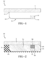
- Figure 1 illustrates a first embodiment of a molding device 10 suitable for molding sunken grooves or surface tie bars in a tire tread.
- a sunken groove is an elongate void area disposed underneath the new tread surface of a tire that is not visible when the tire is new, and that as the tire tread is worn during service, the sunken groove is exposed.
- the sunken groove may be disposed under a surface tire bar that is exposed when the surface tire bar wears away.
- the molding device 10 includes a flexible member 5 having a distal end 11, an optional midsection 13 and one or more molding elements 12 located at a second end 14.
- the distal end 11 may be mounted to a portion of a tire mold 2 in any desired orientation for forming sunken grooves.
- the element 12 may be any desired size, but for example, may be 1-10 mm long, preferably 4-10 mm long, 1-4 mm tall, preferably 2-4 mm, and 5-8 mm deep, preferably 6-8 mm.
- the element 12 may have any desired cross-sectional shape, such as square or rectangular blocks 12. However, the element 12 is not limited to a block shape, and may be curved or have a rounded cross-sectional shape. The depth and thickness of the element 12 may vary.
- the longitudinal axis of the molding device 10 need not be linear, and may be nonlinear for example, curvilinear in shape or any other desired shape.
- the element 12 is made of a rigid material such as metal, for example, steel, aluminum or any other suitable material.
- the element 12 may also be made of a rigid polymer or sintered material.
- the flexible member 5 may be made of metal or any suitable flexible material known by those skilled in the art to be suitable for use in a mold. All or only a portion of the flexible member 5 may comprise elastic, very highly elastic, hyperelastic or superelastic materials such as shape memory alloys including, but not limited to, Nickel-Titanium alloys, CuZnAl, CuAlNi and CuAlBe. It is preferred that the flexible member 5 have an elastic limit greater than or equal to 5% elongation, and more preferably greater than or equal to 10%.
- the molding device 10 as described above may be formed of discrete elements 5, 12 assembled together, or formed as one integral unit such as by electro-erosion cutting.
- the elements 5, 12 may be connected together or connected via an intermediary member.
- the element 12 may be coated with a low friction material or have an optional low friction, protective layer (not shown) covering the element 12
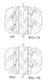
- Figure 2 illustrates one example of the molding device 10 shown in use with an upper portion of a tire mold 2.
- the molding device 10 is embedded in the green tire tread 3 prior to cure.
- the molding device 10 may be mounted to in any desired orientation to the tire mold 2, so that for example, the sunken groove may be oriented circumferentially, axially or any other desired configuration.
- the molding device may be mounted in the segments of the mold corresponding to the crown portion of the tread or located in the portions of the mold corresponding to the sidewalls.
- the tire mold 2 has an inner surface 22 having relief elements 24 for forming a respective groove 34 in a tire tread.
- the molding device 10 is preferably mounted adjacent a relief element 24 to allow extraction of the molding device 10 from the groove.
- the molding element 12 is located adjacent and in contact with relief element 24 to provide structural support for the molding device 10 as it enters the green tire prior to vulcanization. It is preferred that the flexible member has a preformed bend as midsection 13 to match the outer shape of the relief element 24.
- a surface tie bar 36 and a sunken groove portion 38 is formed.
- Figure 4 is a second embodiment of a molding device 40 which is the same as the molding device 10, except that the flexible member 5 is straight.
- Figure 5A illustrates the molding device 40 mounted to the lower surface 42 of the relief element 24 and wherein the sidewall 44 of the relief element 24 is in contact with the sidewall of the molding element 12. The relief element provides structural support to the molding device during insertion into the green tire prior to cure.
- Figure 5B is the same as Figure 5A , except an additional relief element 24 is preferably used so that both sidewalls of the molding element 12 are engaged with opposed walls of relief elements 24A and 24B.
- Figures 6A and 6B illustrate the molding device 40 shown in Figures 5A and 5B , respectively, after extraction from the green tire.
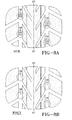
- FIG. 7A and 8A illustrate a new tire tread wherein the circled portion illustrates the surface tire bars 36, which may be oriented in the circumferential direction or the axial direction.
- Figures 7B and 8B illustrate a worn tire tread wherein the circled portions illustrate the portion of the tread revealing new grooves 38 which may be oriented in the circumferential or the axial direction.
- Figure 9 illustrates a third embodiment of the molding device 10, 40 wherein the molding device 10 is as described above, except that the molding device has two or more flexible members 5.
- Figure 10 illustrates a fourth embodiment of the molding device 10/40 wherein the upper portion of the mold 2 has two groove forming elements 24A and 24B which are located adjacent each other.
- the molding device 10/40 is positioned such that the molding element 12 has endwalls 45, 44 which abut with opposed walls 46, 48 of the groove forming elements 24A, B.
- the molding element endwall 44 is conical in shape to interlock with groove forming element 24b.
- the molding element 12 has a magnet for ensuring contact with the groove forming element 24B.
- the magnet may be located in the groove forming element 24B.
Landscapes
- Engineering & Computer Science (AREA)
- Mechanical Engineering (AREA)
- Moulds For Moulding Plastics Or The Like (AREA)
- Tires In General (AREA)
- Heating, Cooling, Or Curing Plastics Or The Like In General (AREA)
Abstract
Description
- The present invention relates to the molding of tires, and in particular, the molding of treads for a tire.
- The tread elements in relief on a tire tread, such as the sipes, tread blocks and grooves, play a fundamental role in tire traction or adhesion to the road both in the transverse direction and in the circumferential direction. Traction is especially critical when travelling on wet or snowy roads. For wet conditions, the grooves act as evacuation channels for trapping and evacuating water to allow the tread blocks to be in contact with the road. In addition, surface tie bars are beneficial when the tire is new, and help to ensure good handling performance.
- As a tire wears, the volume of the tread decreases due to frictional contact with the road surface. As the tire wears, the volume of the tire grooves decrease. As the tire wears, it is desired that the tire bar wears as well, since the tread block height is reduced and the tie bar is no longer necessary. Eventually the tire will require replacement.
- It is known in the prior art to attempt to solve the degrading tread condition through the use of sunken grooves. The sunken grooves, due to a limitation in manufacturing, are generally oriented perpendicular to the shoulder region. Molding elements are typically used to form the sunken grooves, and they are often difficult to remove from the tire once the tire has been cured. To make a sunken groove, the mold elements need to be rigid enough to penetrate the uncured or green rubber tread, but flexible enough to be extracted from the cured tire without damaging the tire. Another requirement is that the sunken groove needs to be large and thick enough to be efficient, which leads to a molding element so stiff that its extraction would damage the tire tread or the element itself would fail by a fatigue fracture. Thus it is desired to have a method and apparatus of forming sunk grooves and surface tie bars that do not have the disadvantages described above.
- The invention relates to a molding device according to claim 1 and a mold according to claim 7. Dependent claims refer to preferred embodiments of the invention.
- The invention will be described by way of example and with reference to the accompanying drawings in which:
-
FIG. 1 is a schematic of a side view of a molding device for molding a sunken grooves and surface tie bar; -
FIG. 2 is a is a side view of the molding device ofFigure 1 shown in use together in a tire mold; -
FIG. 3 is a schematic of a side view of the molding device ofFig. 2 during extraction from the tire mold; -
FIG. 4 is a schematic of side view of a second embodiment of a molding device; -
FIGS. 5 and 5B are side views of the molding device ofFigure 4 shown in use together in a portion of a tire mold during vulcanization of a green tire; -
FIGS. 6A and6B illustrate the molding device being extracted from a portion of a cured tire tread; -
FIGS. 7A and8A illustrate a new tire tread wherein the circled portions illustrate different orientations of a raised tie bar; -
FIGS. 7B and8B illustrate a worn tread wherein the circled portion illustrates the sunken groove now exposed due to wear; -
FIG. 9 is a third embodiment of a molding device; and -
FIG. 10 is a fourth embodiment of a mold and a molding device. -
Figure 1 illustrates a first embodiment of amolding device 10 suitable for molding sunken grooves or surface tie bars in a tire tread. A sunken groove is an elongate void area disposed underneath the new tread surface of a tire that is not visible when the tire is new, and that as the tire tread is worn during service, the sunken groove is exposed. The sunken groove may be disposed under a surface tire bar that is exposed when the surface tire bar wears away. - The
molding device 10 includes aflexible member 5 having adistal end 11, anoptional midsection 13 and one ormore molding elements 12 located at asecond end 14. Thedistal end 11 may be mounted to a portion of atire mold 2 in any desired orientation for forming sunken grooves. Theelement 12 may be any desired size, but for example, may be 1-10 mm long, preferably 4-10 mm long, 1-4 mm tall, preferably 2-4 mm, and 5-8 mm deep, preferably 6-8 mm. Theelement 12 may have any desired cross-sectional shape, such as square orrectangular blocks 12. However, theelement 12 is not limited to a block shape, and may be curved or have a rounded cross-sectional shape. The depth and thickness of theelement 12 may vary. In addition, the longitudinal axis of themolding device 10 need not be linear, and may be nonlinear for example, curvilinear in shape or any other desired shape. - The
element 12 is made of a rigid material such as metal, for example, steel, aluminum or any other suitable material. Theelement 12 may also be made of a rigid polymer or sintered material. - The
flexible member 5 may be made of metal or any suitable flexible material known by those skilled in the art to be suitable for use in a mold. All or only a portion of theflexible member 5 may comprise elastic, very highly elastic, hyperelastic or superelastic materials such as shape memory alloys including, but not limited to, Nickel-Titanium alloys, CuZnAl, CuAlNi and CuAlBe. It is preferred that theflexible member 5 have an elastic limit greater than or equal to 5% elongation, and more preferably greater than or equal to 10%. - The
molding device 10 as described above may be formed ofdiscrete elements elements element 12 may be coated with a low friction material or have an optional low friction, protective layer (not shown) covering theelement 12 -
Figure 2 illustrates one example of themolding device 10 shown in use with an upper portion of atire mold 2. Themolding device 10 is embedded in thegreen tire tread 3 prior to cure. Themolding device 10 may be mounted to in any desired orientation to thetire mold 2, so that for example, the sunken groove may be oriented circumferentially, axially or any other desired configuration. The molding device may be mounted in the segments of the mold corresponding to the crown portion of the tread or located in the portions of the mold corresponding to the sidewalls. Thetire mold 2 has aninner surface 22 havingrelief elements 24 for forming arespective groove 34 in a tire tread. Themolding device 10 is preferably mounted adjacent arelief element 24 to allow extraction of themolding device 10 from the groove. Preferably, themolding element 12 is located adjacent and in contact withrelief element 24 to provide structural support for themolding device 10 as it enters the green tire prior to vulcanization. It is preferred that the flexible member has a preformed bend asmidsection 13 to match the outer shape of therelief element 24. When the molding device is extracted from the curedtread 3, asurface tie bar 36 and asunken groove portion 38 is formed. -
Figure 4 is a second embodiment of amolding device 40 which is the same as themolding device 10, except that theflexible member 5 is straight.Figure 5A illustrates themolding device 40 mounted to thelower surface 42 of therelief element 24 and wherein thesidewall 44 of therelief element 24 is in contact with the sidewall of themolding element 12. The relief element provides structural support to the molding device during insertion into the green tire prior to cure.Figure 5B is the same asFigure 5A , except anadditional relief element 24 is preferably used so that both sidewalls of themolding element 12 are engaged with opposed walls ofrelief elements Figures 6A and6B illustrate themolding device 40 shown inFigures 5A and 5B , respectively, after extraction from the green tire. Asurface tie bar 36 and lowersunken groove 38 is formed when the molding device is removed from the cured tire.Figures 7A and8A illustrate a new tire tread wherein the circled portion illustrates the surface tire bars 36, which may be oriented in the circumferential direction or the axial direction.Figures 7B and8B illustrate a worn tire tread wherein the circled portions illustrate the portion of the tread revealingnew grooves 38 which may be oriented in the circumferential or the axial direction. -
Figure 9 illustrates a third embodiment of themolding device molding device 10 is as described above, except that the molding device has two or moreflexible members 5. -
Figure 10 illustrates a fourth embodiment of themolding device 10/40 wherein the upper portion of themold 2 has twogroove forming elements molding device 10/40 is positioned such that themolding element 12 has endwalls 45, 44 which abut with opposedwalls groove forming elements 24A, B. Preferably, themolding element endwall 44 is conical in shape to interlock with groove forming element 24b. More preferably, themolding element 12 has a magnet for ensuring contact with thegroove forming element 24B. Alternatively, the magnet may be located in thegroove forming element 24B.
Claims (10)
- A molding device for forming a sunken groove (38) in a tire, the molding device (10) comprising one or more rigid elements (12), and a flexible member (5), wherein the one or more rigid elements (12) are connected to the flexible member (5).
- The molding device of claim 1 wherein the flexible member (5) is formed from a superelastic alloy.
- The molding device of claim 1 or 2 wherein the flexible member (5) is formed from a material having an elastic limit greater than or equal to 5% elongation, alternately greater than or equal to 10% elongation.
- The molding device of at least on of the previous claims wherein the one or more rigid elements (12) have a square or rectangular cross sectional shape.
- The molding device of at least one of the previous claims 1-4 wherein the rigid elements have a rounded cross sectional shape.
- The molding device of at least one of the previous claims wherein the molding device (10) comprises a plurality of rigid elements (12) mounted on said flexible member (5).
- A mold for molding a tread band of a tire, the tread band being made of an elastomer compound, the mold (2) comprising a mold surface for molding the tread and a molding device (10, 40) according to one of the previous claims projecting from the mold surface so as to become embedded in the elastomer compound to be molded, wherein the mold (2) has a relief forming element (24), and wherein a portion of the flexible member (5) is positioned in contact with a first surface of the relief forming element (24) and the rigid element (12) has a mating surface in mating contact with a second surface of the relief forming element (24).
- The mold of claim 7 wherein the mold (2) further comprises a second relief forming element (24B) positioned adjacent said first relief forming element (24), wherein the rigid element (12) includes an outer surface in mating contact with a surface of said second relief forming element (24B).
- The mold of claim 7 or 8 wherein the molding device (10) further comprises a magnet and/or wherein the surface of said second relief forming element has a magnet for engaging the molding device (10).
- The mold of at least one of the claims 7-9 wherein the outer surface of the rigid element (12) is conical in shape for interlocking with the surface of said second relief forming element.
Applications Claiming Priority (1)
| Application Number | Priority Date | Filing Date | Title |
|---|---|---|---|
| US87621006P | 2006-12-21 | 2006-12-21 |
Publications (2)
| Publication Number | Publication Date |
|---|---|
| EP1938956A1 true EP1938956A1 (en) | 2008-07-02 |
| EP1938956B1 EP1938956B1 (en) | 2010-05-05 |
Family
ID=39129104
Family Applications (1)
| Application Number | Title | Priority Date | Filing Date |
|---|---|---|---|
| EP07123449A Ceased EP1938956B1 (en) | 2006-12-21 | 2007-12-18 | Flexible molding device for manufacturing a sunken groove or surface tie bar in a tire tread |
Country Status (6)
| Country | Link |
|---|---|
| US (1) | US7544053B2 (en) |
| EP (1) | EP1938956B1 (en) |
| JP (1) | JP5122936B2 (en) |
| CN (1) | CN101229668A (en) |
| BR (1) | BRPI0704951A (en) |
| DE (1) | DE602007006270D1 (en) |
Families Citing this family (3)
| Publication number | Priority date | Publication date | Assignee | Title |
|---|---|---|---|---|
| BRPI0903293B1 (en) * | 2008-09-11 | 2020-10-13 | The Goodyear Tire & Rubber Company | tire having a tire tread |
| CN104002369A (en) * | 2014-05-30 | 2014-08-27 | 无锡正大轴承机械制造有限公司 | Working face-replaceable refractory brick/tile mould |
| JP6511351B2 (en) * | 2015-07-02 | 2019-05-15 | 住友ゴム工業株式会社 | Pneumatic tire |
Citations (10)
| Publication number | Priority date | Publication date | Assignee | Title |
|---|---|---|---|---|
| US2770013A (en) * | 1951-02-28 | 1956-11-13 | Lloyd L Felker | Stud holders for use in tire molds |
| DE1274799B (en) * | 1964-11-28 | 1968-08-08 | Ernst Schuhknecht | Insert strips for gripper claws to be vulcanized into the raw tread of a pneumatic vehicle tire in a vulcanizing mold |
| EP0450251A1 (en) * | 1990-02-22 | 1991-10-09 | The Goodyear Tire & Rubber Company | Tire treads |
| WO1999021701A1 (en) * | 1997-10-27 | 1999-05-06 | The Goodyear Tire & Rubber Company | Article and method for composite tire mold blades |
| US6193492B1 (en) | 1997-04-24 | 2001-02-27 | COMPAGNIE GéNéRALE DES ETABLISSEMENTS MICHELIN - MICHELIN & CIE | Element for molding a pattern in a tread |
| US6408910B1 (en) | 1997-05-30 | 2002-06-25 | Compagnie Generale Des Establishments Michelin-Michelin Cie | Tread including recessed channel and recessed incision and mold for tread |
| EP1243390A2 (en) * | 2001-03-23 | 2002-09-25 | The Goodyear Tire & Rubber Company | Composite blade for a tire curing mould |
| EP1275527A2 (en) * | 2001-07-10 | 2003-01-15 | Continental Aktiengesellschaft | Tread profile for a tyre, pin for the manufacture of such a tread profile and a mold with such a pin |
| EP1586438A1 (en) * | 2004-04-13 | 2005-10-19 | Société de Technologie Michelin | Tire mould and tread made by this mould |
| EP1676695A2 (en) | 2004-12-30 | 2006-07-05 | The Goodyear Tire & Rubber Company | Device for molding a keyhole sipe in a tire tread |
Family Cites Families (11)
| Publication number | Priority date | Publication date | Assignee | Title |
|---|---|---|---|---|
| US5075067A (en) * | 1988-02-08 | 1991-12-24 | The Uniroyal Goodrich Tire Company | Tire and method of producing same |
| FR2729329A1 (en) * | 1995-01-18 | 1996-07-19 | Michelin & Cie | PROCESS AND DEVICE FOR PRODUCING AT LEAST ONE TIRE MOLD COMPRISING AT LEAST ONE MOLDING ELEMENT WITH A NON-DEMOLDABLE PATTERN |
| FR2772663A1 (en) | 1997-12-24 | 1999-06-25 | Michelin & Cie | METHOD AND MOLDING ELEMENT FOR MOLDING A CUT IN A TIRE TRUCK |
| ATE289260T1 (en) | 2000-11-13 | 2005-03-15 | Michelin Soc Tech | TIRE TREAD AND MOLDING ELEMENT OF A MOLDING TOOL FOR SUCH TREAD |
| EP1232852B1 (en) | 2001-02-20 | 2006-09-27 | Société de Technologie Michelin | Mould and method for moulding a tyre tread |
| ATE325000T1 (en) * | 2002-05-15 | 2006-06-15 | Michelin Soc Tech | SCALABLE TREAD |
| US7276198B2 (en) | 2004-12-28 | 2007-10-02 | The Goodyear Tire & Rubber Company | Method and mold for making tire with tie bar |
| US7188650B2 (en) | 2004-12-28 | 2007-03-13 | The Goodyear Tire & Rubber Company | Siped tire tread with high transverse stiffness |
| US7290578B2 (en) | 2004-12-30 | 2007-11-06 | The Goodyear Tire & Rubber Company | Tire tread having a tread block with an undercut design |
| FR2891489B1 (en) * | 2005-10-04 | 2007-12-07 | Michelin Soc Tech | MOLD FOR TIRE TREAD. |
| US7575424B2 (en) * | 2006-12-21 | 2009-08-18 | The Goodyear Tire & Rubber Company | Flexible molding device for manufacturing a sunken groove in a tire tread |
-
2007
- 2007-08-14 US US11/891,970 patent/US7544053B2/en not_active Expired - Fee Related
- 2007-12-14 BR BRPI0704951-0A patent/BRPI0704951A/en not_active IP Right Cessation
- 2007-12-18 EP EP07123449A patent/EP1938956B1/en not_active Ceased
- 2007-12-18 DE DE602007006270T patent/DE602007006270D1/en active Active
- 2007-12-21 JP JP2007330298A patent/JP5122936B2/en not_active Expired - Fee Related
- 2007-12-21 CN CNA2007101621786A patent/CN101229668A/en active Pending
Patent Citations (10)
| Publication number | Priority date | Publication date | Assignee | Title |
|---|---|---|---|---|
| US2770013A (en) * | 1951-02-28 | 1956-11-13 | Lloyd L Felker | Stud holders for use in tire molds |
| DE1274799B (en) * | 1964-11-28 | 1968-08-08 | Ernst Schuhknecht | Insert strips for gripper claws to be vulcanized into the raw tread of a pneumatic vehicle tire in a vulcanizing mold |
| EP0450251A1 (en) * | 1990-02-22 | 1991-10-09 | The Goodyear Tire & Rubber Company | Tire treads |
| US6193492B1 (en) | 1997-04-24 | 2001-02-27 | COMPAGNIE GéNéRALE DES ETABLISSEMENTS MICHELIN - MICHELIN & CIE | Element for molding a pattern in a tread |
| US6408910B1 (en) | 1997-05-30 | 2002-06-25 | Compagnie Generale Des Establishments Michelin-Michelin Cie | Tread including recessed channel and recessed incision and mold for tread |
| WO1999021701A1 (en) * | 1997-10-27 | 1999-05-06 | The Goodyear Tire & Rubber Company | Article and method for composite tire mold blades |
| EP1243390A2 (en) * | 2001-03-23 | 2002-09-25 | The Goodyear Tire & Rubber Company | Composite blade for a tire curing mould |
| EP1275527A2 (en) * | 2001-07-10 | 2003-01-15 | Continental Aktiengesellschaft | Tread profile for a tyre, pin for the manufacture of such a tread profile and a mold with such a pin |
| EP1586438A1 (en) * | 2004-04-13 | 2005-10-19 | Société de Technologie Michelin | Tire mould and tread made by this mould |
| EP1676695A2 (en) | 2004-12-30 | 2006-07-05 | The Goodyear Tire & Rubber Company | Device for molding a keyhole sipe in a tire tread |
Also Published As
| Publication number | Publication date |
|---|---|
| CN101229668A (en) | 2008-07-30 |
| JP5122936B2 (en) | 2013-01-16 |
| EP1938956B1 (en) | 2010-05-05 |
| BRPI0704951A (en) | 2008-08-12 |
| JP2008155640A (en) | 2008-07-10 |
| DE602007006270D1 (en) | 2010-06-17 |
| US7544053B2 (en) | 2009-06-09 |
| US20080152740A1 (en) | 2008-06-26 |
Similar Documents
| Publication | Publication Date | Title |
|---|---|---|
| EP1938938B1 (en) | Flexible molding device for molding a sunk groove, a sunk blade, and a large keyhole sipe in a tire tread | |
| EP1938939B1 (en) | Flexible enrobed molding device for manufacturing a sunken groove in a tire tread | |
| EP1935602A1 (en) | A flexible molding device for manufacturing a sunken groove in a tire tread | |
| EP3200987B1 (en) | Stiffeners for sipe-molding members | |
| CN104837654B (en) | The tyre surface of snow tire including otch and cavity | |
| EP2028024B1 (en) | Precured tread and retreaded tire | |
| EP1616719A1 (en) | Pneumatic tire | |
| EP1676695B1 (en) | Mold with a device for molding a keyhole sipe in a tire tread | |
| JPH04215506A (en) | Tire tread | |
| CN103492196A (en) | Tread including at least one wavy groove, and method for producing same | |
| US8127811B2 (en) | Sipe blade and tire molded using the same | |
| EP2517867B1 (en) | Blade for a mold, mold segment or mold comprising such a blade and method of securing a mold blade to a mold segment | |
| EP1938956B1 (en) | Flexible molding device for manufacturing a sunken groove or surface tie bar in a tire tread | |
| US20190344842A1 (en) | Rubber crawler, rubber crawler mold, and method of producing rubber crawler | |
| EP1935601B1 (en) | Flexible molding device for manufacturing a sunken groove in a tire tread | |
| JP4390138B2 (en) | Tire vulcanization mold | |
| KR20100052940A (en) | A tire curing mould | |
| KR101995794B1 (en) | Heavy Duty Pneumatic Tire with Waved Groove | |
| EP3356102B1 (en) | Molding element for manufacturing a noise reducing tread |
Legal Events
| Date | Code | Title | Description |
|---|---|---|---|
| PUAI | Public reference made under article 153(3) epc to a published international application that has entered the european phase |
Free format text: ORIGINAL CODE: 0009012 |
|
| AK | Designated contracting states |
Kind code of ref document: A1 Designated state(s): AT BE BG CH CY CZ DE DK EE ES FI FR GB GR HU IE IS IT LI LT LU LV MC MT NL PL PT RO SE SI SK TR |
|
| AX | Request for extension of the european patent |
Extension state: AL BA HR MK RS |
|
| 17P | Request for examination filed |
Effective date: 20090105 |
|
| AKX | Designation fees paid |
Designated state(s): DE FR IT |
|
| 17Q | First examination report despatched |
Effective date: 20090217 |
|
| GRAP | Despatch of communication of intention to grant a patent |
Free format text: ORIGINAL CODE: EPIDOSNIGR1 |
|
| GRAS | Grant fee paid |
Free format text: ORIGINAL CODE: EPIDOSNIGR3 |
|
| GRAA | (expected) grant |
Free format text: ORIGINAL CODE: 0009210 |
|
| AK | Designated contracting states |
Kind code of ref document: B1 Designated state(s): DE FR IT |
|
| REF | Corresponds to: |
Ref document number: 602007006270 Country of ref document: DE Date of ref document: 20100617 Kind code of ref document: P |
|
| PLBE | No opposition filed within time limit |
Free format text: ORIGINAL CODE: 0009261 |
|
| STAA | Information on the status of an ep patent application or granted ep patent |
Free format text: STATUS: NO OPPOSITION FILED WITHIN TIME LIMIT |
|
| 26N | No opposition filed |
Effective date: 20110208 |
|
| REG | Reference to a national code |
Ref country code: DE Ref legal event code: R097 Ref document number: 602007006270 Country of ref document: DE Effective date: 20110207 |
|
| PG25 | Lapsed in a contracting state [announced via postgrant information from national office to epo] |
Ref country code: IT Free format text: LAPSE BECAUSE OF NON-PAYMENT OF DUE FEES Effective date: 20101218 |
|
| REG | Reference to a national code |
Ref country code: FR Ref legal event code: PLFP Year of fee payment: 9 |
|
| REG | Reference to a national code |
Ref country code: FR Ref legal event code: PLFP Year of fee payment: 10 |
|
| REG | Reference to a national code |
Ref country code: FR Ref legal event code: PLFP Year of fee payment: 11 |
|
| PGFP | Annual fee paid to national office [announced via postgrant information from national office to epo] |
Ref country code: FR Payment date: 20171120 Year of fee payment: 11 |
|
| PGFP | Annual fee paid to national office [announced via postgrant information from national office to epo] |
Ref country code: IT Payment date: 20171219 Year of fee payment: 11 |
|
| PGFP | Annual fee paid to national office [announced via postgrant information from national office to epo] |
Ref country code: DE Payment date: 20171221 Year of fee payment: 11 |
|
| REG | Reference to a national code |
Ref country code: DE Ref legal event code: R119 Ref document number: 602007006270 Country of ref document: DE |
|
| PG25 | Lapsed in a contracting state [announced via postgrant information from national office to epo] |
Ref country code: DE Free format text: LAPSE BECAUSE OF NON-PAYMENT OF DUE FEES Effective date: 20190702 Ref country code: IT Free format text: LAPSE BECAUSE OF NON-PAYMENT OF DUE FEES Effective date: 20181218 Ref country code: FR Free format text: LAPSE BECAUSE OF NON-PAYMENT OF DUE FEES Effective date: 20181231 |