EP1938742A1 - Washer disinfector equipped with bath to which tray with endoscope mounted thereon is detachably loaded - Google Patents
Washer disinfector equipped with bath to which tray with endoscope mounted thereon is detachably loaded Download PDFInfo
- Publication number
- EP1938742A1 EP1938742A1 EP07024318A EP07024318A EP1938742A1 EP 1938742 A1 EP1938742 A1 EP 1938742A1 EP 07024318 A EP07024318 A EP 07024318A EP 07024318 A EP07024318 A EP 07024318A EP 1938742 A1 EP1938742 A1 EP 1938742A1
- Authority
- EP
- European Patent Office
- Prior art keywords
- endoscope
- tray
- positioning
- hole
- mouth ring
- Prior art date
- Legal status (The legal status is an assumption and is not a legal conclusion. Google has not performed a legal analysis and makes no representation as to the accuracy of the status listed.)
- Granted
Links
Images



Classifications
-
- A—HUMAN NECESSITIES
- A61—MEDICAL OR VETERINARY SCIENCE; HYGIENE
- A61L—METHODS OR APPARATUS FOR STERILISING MATERIALS OR OBJECTS IN GENERAL; DISINFECTION, STERILISATION OR DEODORISATION OF AIR; CHEMICAL ASPECTS OF BANDAGES, DRESSINGS, ABSORBENT PADS OR SURGICAL ARTICLES; MATERIALS FOR BANDAGES, DRESSINGS, ABSORBENT PADS OR SURGICAL ARTICLES
- A61L2/00—Disinfection or sterilisation of materials or objects, in general; Accessories therefor
- A61L2/16—Disinfection or sterilisation of materials or objects, in general; Accessories therefor using chemical substances
- A61L2/20—Gaseous substances, e.g. vapours
-
- A—HUMAN NECESSITIES
- A61—MEDICAL OR VETERINARY SCIENCE; HYGIENE
- A61L—METHODS OR APPARATUS FOR STERILISING MATERIALS OR OBJECTS IN GENERAL; DISINFECTION, STERILISATION OR DEODORISATION OF AIR; CHEMICAL ASPECTS OF BANDAGES, DRESSINGS, ABSORBENT PADS OR SURGICAL ARTICLES; MATERIALS FOR BANDAGES, DRESSINGS, ABSORBENT PADS OR SURGICAL ARTICLES
- A61L2/00—Disinfection or sterilisation of materials or objects, in general; Accessories therefor
- A61L2/24—Apparatus using programmed or automatic operation
-
- A—HUMAN NECESSITIES
- A61—MEDICAL OR VETERINARY SCIENCE; HYGIENE
- A61B—DIAGNOSIS; SURGERY; IDENTIFICATION
- A61B1/00—Instruments for performing medical examinations of the interior of cavities or tubes of the body by visual or photographical inspection, e.g. endoscopes; Illuminating arrangements therefor
- A61B1/12—Instruments for performing medical examinations of the interior of cavities or tubes of the body by visual or photographical inspection, e.g. endoscopes; Illuminating arrangements therefor with cooling or rinsing arrangements
- A61B1/121—Instruments for performing medical examinations of the interior of cavities or tubes of the body by visual or photographical inspection, e.g. endoscopes; Illuminating arrangements therefor with cooling or rinsing arrangements provided with means for cleaning post-use
- A61B1/123—Instruments for performing medical examinations of the interior of cavities or tubes of the body by visual or photographical inspection, e.g. endoscopes; Illuminating arrangements therefor with cooling or rinsing arrangements provided with means for cleaning post-use using washing machines
-
- A—HUMAN NECESSITIES
- A61—MEDICAL OR VETERINARY SCIENCE; HYGIENE
- A61B—DIAGNOSIS; SURGERY; IDENTIFICATION
- A61B90/00—Instruments, implements or accessories specially adapted for surgery or diagnosis and not covered by any of the groups A61B1/00 - A61B50/00, e.g. for luxation treatment or for protecting wound edges
- A61B90/70—Cleaning devices specially adapted for surgical instruments
-
- A—HUMAN NECESSITIES
- A61—MEDICAL OR VETERINARY SCIENCE; HYGIENE
- A61L—METHODS OR APPARATUS FOR STERILISING MATERIALS OR OBJECTS IN GENERAL; DISINFECTION, STERILISATION OR DEODORISATION OF AIR; CHEMICAL ASPECTS OF BANDAGES, DRESSINGS, ABSORBENT PADS OR SURGICAL ARTICLES; MATERIALS FOR BANDAGES, DRESSINGS, ABSORBENT PADS OR SURGICAL ARTICLES
- A61L2/00—Disinfection or sterilisation of materials or objects, in general; Accessories therefor
- A61L2/16—Disinfection or sterilisation of materials or objects, in general; Accessories therefor using chemical substances
-
- A—HUMAN NECESSITIES
- A61—MEDICAL OR VETERINARY SCIENCE; HYGIENE
- A61L—METHODS OR APPARATUS FOR STERILISING MATERIALS OR OBJECTS IN GENERAL; DISINFECTION, STERILISATION OR DEODORISATION OF AIR; CHEMICAL ASPECTS OF BANDAGES, DRESSINGS, ABSORBENT PADS OR SURGICAL ARTICLES; MATERIALS FOR BANDAGES, DRESSINGS, ABSORBENT PADS OR SURGICAL ARTICLES
- A61L2/00—Disinfection or sterilisation of materials or objects, in general; Accessories therefor
- A61L2/16—Disinfection or sterilisation of materials or objects, in general; Accessories therefor using chemical substances
- A61L2/18—Liquid substances
-
- A—HUMAN NECESSITIES
- A61—MEDICAL OR VETERINARY SCIENCE; HYGIENE
- A61L—METHODS OR APPARATUS FOR STERILISING MATERIALS OR OBJECTS IN GENERAL; DISINFECTION, STERILISATION OR DEODORISATION OF AIR; CHEMICAL ASPECTS OF BANDAGES, DRESSINGS, ABSORBENT PADS OR SURGICAL ARTICLES; MATERIALS FOR BANDAGES, DRESSINGS, ABSORBENT PADS OR SURGICAL ARTICLES
- A61L2/00—Disinfection or sterilisation of materials or objects, in general; Accessories therefor
- A61L2/16—Disinfection or sterilisation of materials or objects, in general; Accessories therefor using chemical substances
- A61L2/22—Phase substances, e.g. smokes or aerosols
-
- A—HUMAN NECESSITIES
- A61—MEDICAL OR VETERINARY SCIENCE; HYGIENE
- A61B—DIAGNOSIS; SURGERY; IDENTIFICATION
- A61B90/00—Instruments, implements or accessories specially adapted for surgery or diagnosis and not covered by any of the groups A61B1/00 - A61B50/00, e.g. for luxation treatment or for protecting wound edges
- A61B90/70—Cleaning devices specially adapted for surgical instruments
- A61B2090/701—Cleaning devices specially adapted for surgical instruments for flexible tubular instruments, e.g. endoscopes
Definitions
- the present invention relates to a washer disinfector that washes and disinfects endoscopes for medical use (hereinafter referred to as an "endoscope washer disinfector"), and, in particular, to an endoscope washer disinfector equipped with a washing disinfecting bath and automatically washes and disinfects an endoscope accommodated within the washing disinfecting bath.
- an endoscope washer disinfector equipped with a washing disinfecting bath and automatically washes and disinfects an endoscope accommodated within the washing disinfecting bath.
- Medical endoscopes have now grown into indispensable modalities for inspection and treatment of patients' body cavities. Once such an endoscope is used, the outer surface of the insertion tube inserted into a body cavity as well as the insides of various ducts, such as the air-supply water-supply duct, suction duct, forward water-supply duct, and/or therapeutic duct, of the endoscope are polluted with waste materials. Hence it is necessary that the outer surface of a used endoscope and the insides of each duct thereof are always washed and disinfected.
- an endoscope washer disinfector i.e., an apparatus for washing and disinfecting endoscopes.
- a used endoscope is accommodated into a washing disinfecting bath, which is within the main body of this endoscope washer disinfector, and positionally fixed therein.
- the mouth rings of the ducts which are open to the outside, are connected to various nozzles within the washer disinfector via tubes.
- the nozzles which are for supplying various kinds of fluid and gas necessary for washing and disinfection, are arranged as part of a supply unit attached to the washing disinfecting bath.
- the supply unit is arranged to receive the various kinds of fluid and gas from containers.
- the washing disinfecting bath is then closed by a lid member attached thereto, before a start switch is set "on" for starting the processes of washing and disinfection.
- the washer disinfector performs a water leakage check to confirm whether the endoscope has a water leakage. If there is no water leakage, processes including a washing step, a rinsing step, a disinfecting step, and a drying step are performed in sequence.
- the endoscope washer disinfector which has the capability of washing and disinfecting the insides of the ducts as well as the outer surface of the endoscope.
- the endoscope washer disinfector according to the foregoing publication is also confronted with another difficulty.
- an endoscope Once an endoscope is used for an examination and/or a treatment, it is normal that the endoscope is subjected to adhesion of contamination from body fluid, blood, and others. It is thus necessary to prevent the contamination from spreading to personnel and surroundings during the delivery of endoscopes to the washer disinfector.
- a used endoscope is mounted on a dedicated tray and delivered to the washer disinfector.
- the used endoscope When being delivered to the washer disinfector using the tray, the used endoscope is then accommodated into the washing disinfecting bath in one of two ways.
- One way is to accommodate the endoscope using the engagement mechanism described in Japanese Patent Application Publication (Laid-open) No. 2006-95084 .
- the other way is to make use of the tray itself. That is, with the endoscope kept mounted on the tray, the tray is loaded into the washing disinfecting bath. This kind of endoscope washer disinfector is known as well.
- a used endoscope should be set accurately in position on the tray, and the tray should be set accurately within the washing disinfecting bath.
- the present invention has been made in consideration of the above difficulties, and an object of the present invention is to provide an endoscope washer disinfector which is able to give higher positioning accuracy between a mouth ring of the endoscope, which communicate with a duct formed therethrough, and a nozzle for supplying fluid necessary for washing and disinfection to the mouth ring, when a tray with the endoscope mounted thereon is loaded into the washing disinfecting bath of an endoscope washer disinfector.
- an endoscope washer disinfector (1) for washing and disinfecting an endoscope (20) equipped with a mouth ring (25) communicating with a duct formed within through the endoscope.
- the endoscope washer disinfector comprises a washing disinfecting bath (5) in which the endoscope is accommodated; a nozzle (31) arranged within the washing disinfecting bath, loaded into the mouth ring of the endoscope, and in charge of supplying fluid to the duct via the mouth ring; and a tray (10) on which the endoscope is mounted and which is detachably loaded into the washing disinfecting bath.
- the endoscope washer disinfector further comprises a bilateral positioning member (11, 22; 23, 111, 112) and a trilateral positioning member (12, 6, 21; 23, 106).
- the bilateral positioning member (11, 22; 23, 111, 112) positions the endoscope and the tray so that the mouth ring of the endoscope mounted on the tray is located at a given position on the tray.
- the trilateral positioning member (12, 6, 21; 23, 106) positions the washing disinfecting bath, the tray, and the endoscope so that, when the tray is loaded into the washing disinfecting bath, the mouth ring of the endoscope positioned at the given position on the tray by the bilateral positioning member is positioned at a position that is across from the nozzle.
- the bilateral and trilateral positioning members work so that the mouth ring of the endoscope is highly accurately located at the position facing the nozzle.
- an endoscope washer disinfector 1 for washing and disinfecting a used endoscope 20 and accessories thereof.
- the endoscope washer disinfector 1 is equipped, as its major components, with a main body 2 and a cover 3 which can open and close the top of the main body 2 by for example hinges fixed to an edge of the top.
- a washing disinfecting bath unit 50 is arranged to provide a washing disinfecting bath S.
- This bath 5 has a given depth as illustrated in Fig. 5A and has an opening facing upward, through which an endoscope 20 is inserted and removed.
- a not-shown fluid supply unit is placed to automatically supply various types of fluid, such as liquid (including washing liquid, disinfectant liquid, and rinsing water) and gas (including air), to each duct (called “channel") of an endoscope 20 accommodated within the washing disinfecting bath 5.
- the fluid supply unit comprises a nozzle 31 to supply such a fluid and is located outside the washing disinfecting bath 5 so that the nozzle 5 is directed toward the bath 5.
- ducts i.e., channels
- various ducts i.e., channels
- an air-supply water-supply duct a forward water-supply duct
- a therapeutic-instrument insertion duct serving a suction duct as well.
- the nozzle 31 will now be explained as a nozzle member to automatically supply fluid into the therapeutic-instrument insertion duct.
- the nozzle 31 is structured to be automatically connected with a mouth ring (mouth piece) 25 (refer to Fig. 3 ) of the therapeutic-instrument insertion duct, which is also known.
- the structure of the fluid supply unit is known. Those known structures will be omitted from the following explanations.
- the washing disinfecting bath 5 has a bottom 5t, in which there is formed a drain outlet 5h to drain away, from the washing disinfecting bath 5, various types of fluid such as washing liquid, disinfectant liquid and rinsing water at a central part of the bottom of the bath. Further, on the bottom 5t, there are formed plural linear grooves 7 which serve as locating means for the tray 10. These grooves 7 extend substantially radially along the face of the bottom.
- the plural grooves 7 guide the liquid in the washing disinfecting bath 5 to the drain outlet 5h.
- the plural grooves 7 function to decide the loading direction of the tray 10 relative to the washing disinfecting bath 5. That is, plural tubular convex parts PT are formed on the rear face of the tray 10 (refer to Fig. 5B ). The convex parts PT can be fit into the grooves 7, when the tray 10 is loaded into the washing disinfecting bath 5, so that the tray 10 can be oriented automatically in the bath.
- the directions of the plural grooves 7 are designed such that a fluid-supply-nozzle insertion opening 13 (later described) (hereinafter simply referred to as an "insertion opening") of the tray 10 is located at a position where a supply nozzle 31 exists.
- the endoscope 20 has a manipulating device 20m and a mouth ring 25 located and formed on the manipulating device 20 and connected to the therapeutic-instrument insertion duct passing through the device 20m, as shown in Fig. 3 .
- the plural grooves 7 decide the loading direction of the tray 10 in a manner that the manipulating device 20m of the endoscope 20 accommodated in the tray 10 approaches the supply nozzle 31 and the mouth ring 25 thereof is located at a position, where the supply nozzle 31 can be connected automatically with the mouth ring 25.
- the pin position is adjacent to one of the grooves 7, which approaches the supply nozzle 31.
- the first positioning pin 6 When the tray 10 which accommodates the endoscope 20 is loaded into the washing disinfecting bath 5, the first positioning pin 6 is fit into a first through-hole 21 (later described) formed at the endoscope 20 in a manner that all the circumferential surface of the first positioning pin 6 comes closely in contact with the first through-hole 21. This fitting operation allows the endoscope 20 to be located to the washing disinfecting bath 5. Furthermore, the first positioning pin 6 is made to penetrate through a first positioning-pin insertion hole 12 (refer to Fig. 4 ) formed in the tray 10, which will also be described later. This operation allows the tray 10 to be located to the washing disinfecting bath 5.
- the first positioning pin 6 has the capability to position both the tray 10 and the endoscope 20.
- the endoscope 20 is arranged such that the manipulating device 20m of the endoscope 20 is made to approach the supply nozzle to have the mouth ring 25 thereof located at the automatic connection position facing the supply nozzle 31.
- the tray 10 is detachable from the washing disinfecting bath 5 and the endoscope 20 can be accommodated and removed into and from the tray 10.
- the tray 10 has an outer contour of size almost the same as that of the inner contour of the washing disinfecting bath 5, when being viewed vertically to the bath.
- the tray 10 is formed into a top-face-open case that comprises a side wall (plane) 10g standing up at from the surrounding edge of the base 10t.
- an insertion opening 13 is located which allows the supply nozzle 31 to be inserted therethrough and which faces the mouth ring 25 of the endoscope 20 accommodated in the tray 10.
- the bottom 10t of the tray 10 has a rear side, which faces the washing disinfecting bath 5 when the tray 10 is loaded into the bath 5.
- the foregoing plural tubular convex parts PT (refer to Fig. 5B ) are formed to be fit into the grooves of the bath 5.
- the tubular convex parts PT are not limited in their shape to the one described.
- An alternative example is that each convex part is composed of a plurality of locally protruded parts which form a line.
- the endoscope 20 has, as its essential components, a thin and long flexible insertion tube 20s and a manipulating device 20m (refer to Fig. 3 ) integral with the insertion tube.
- the endoscope 20 is accommodated in the tray 10 in its rounded and wound attitude of the insertion tube 20s.
- the tray 10 provides a circular insertion-tube accommodation space 10s, in which the insertion tube 20s of the endoscope 20 can be accommodated, and a manipulating-device accommodation space 10m, in which the manipulating device 20m is accommodated (refer to Fig. 3 ).
- the tray 10 further provides a remote-control accommodation space 10r, in which a remote control can be accommodated. This remote control is used for manipulating the insertion tube 20s equipped with a bendable portion bendable using electronic power.
- a drain port 10h to drain away fluid, such as washing liquid, disinfectant liquid, rising water, and alcohol, to the outside thereof.
- the insertion opening 13 is formed at the side wall 10g.
- the first positioning-pin insertion hole 12 is formed to have a contour which is tightly in contact with the whole periphery of the first positioning pin 6. This insertion hole 12 is located to positionally correspond to the position of the first positioning pin 6 when the tray 10 is loaded into the washing disinfecting bath 5.
- a cylindrical second positioning pin 11 is formed to stand up from the bottom 10t. The position of this second positioning pin 11 is close to the first positioning-pin insertion hole 12.
- the second positioning pin 11 can be fitted into a later-described second through-hole 22 formed at the endoscope 20. Actually this insertion is carried out such that the entire periphery of this second positioning pin 11 closely contacts the second through-hole 22, thus enabling the endoscope 20 to be located relative to the tray 10.
- the second positioning pin 11 is located so that the mouth ring 25 (refer to Fig. 3 ) of the endoscope 20 accommodated in the tray 10 is opposite to the insertion opening 13. According to this, when the tray 10 is loaded into the washing disinfecting bath 5, the second positioning pin 11 locates the endoscope 20 in the tray 10 such that the mouth ring 25 is fixed at the automatic connection position where the supply nozzle 31 directly faces the mouth ring 25.
- the manipulating device 20m of the endoscope 20 has the first through-hole 21, which is a positioning through-hole through which the first positioning pin 6 is tightly inserted, and the second through-hole 22, which is a positioning through-hole through which the second positioning pin 11 is tightly inserted.
- the first through-hole 21 and the second through-hole 22 have diameters so that the though-holes 21 and 22 tightly accept the first and second positioning pins 6 and 11, respectively.
- Each of the first and second through-holes 21 and 22 may not be limited to a through-hole like this embodiment, as this is not a definitive list.
- the through-holes may be replaced by bottomed holes.
- the mouth ring 25 which communicates with the therapeutic-instrument insertion duct, is mounted on the manipulating device 20m to be oblique by a given angle to an axis along the manipulating device 20m.
- the used endoscope 20 is first accommodated into the tray 10, before the tray 10 is loaded into the washing disinfecting bath 5.
- the insertion tube 20s is wound as illustrated in Fig. 3 , and accommodated in the insertion-tube accommodating space 10s, as illustrated in Fig. 1 , during which time the manipulating device 20m is placed into the manipulating-device accommodating space 10m.
- the second positioning pin 11 standing up from the bottom 10t of the space 10m is tightly fit into the second through-hole 22 formed through the manipulating device 20m, as shown in Figs. 1 and 2 .
- the endoscope 20 in the tray is located to the tray 10 so that the mouth ring 25 is opposite to the insertion opening 13 of the tray 10.
- the remote control is also accommodated into the remote-control accommodation space 10r of the tray 10.
- the tray 10, in which the endoscope 20 is secured is carried to the endoscope washer disinfector 1, and then loaded into the washing disinfecting bath 5.
- This loading action is performed as follows.
- the tubular convex parts PT formed on the rear side of the bottom 10t (i.e., mounting plane) of the tray 10 are fitted into the grooves 7 formed on the bottom 5t of the washing disinfecting bath 5 so that the tray 10 is oriented firmly.
- the first positioning-pin insertion hole 12 of the tray 10 accepts the insertion of the first positioning pin 6 standing up from the bottom 5t.
- the first through-hole 21 of the manipulating device 20m accepts tight insertion of the first positioning pin 6, before completion of loading the tray 10 with the used endoscope 20 to the washing disinfecting bath 5.
- a combination of the plural grooves 7 and the first positioning pin 6 allows the manipulating device 20m to be located close to the supply nozzle 31.
- the mouth ring 25 of the endoscope 20 is present at the automatic connection position which is directly opposed to the supply nozzle 31, resulting in that the endoscope 20 is ready for washing and disinfection at the given position.
- the endoscope 20 which is accommodated in the tray 10, is also accommodated and located with precision in the washing disinfecting bath 5. Then the top cover 3 is closed on the main body 2, and the endoscopic washer disinfector 1 is switched on. In response to this action, the supply nozzle 31 is moved the automatic connection position, where the nozzle 31 is automatically connected with the mouth ring 25 that has been located in front of the supply nozzle 31. This loading action is followed by supplying various types of fluid into the therapeutic-instrument insertion duct via the mouth ring 25 during each of the processing steps for washing and disinfection of the endoscope 20.
- the plural grooves 7 are formed on the bottom 5t of the washing disinfecting bath 5 to orient the tray 10 to the given loading direction in the base 5.
- the manipulating device 20m of the endoscope 20 has the first through-hole 21 through which the first positioning pin 6 is fit for fixedly positioning both the tray 10 and the endoscope 20 relative to the bath 5.
- the first positioning-pin insertion hole 12 accepts the insertion of the first positioning pin 6 therethrough.
- the second through-hole 22 of the manipulating device 20m accepts the insertion of the second positioning pin 11 so that the endoscope 20 is securely fixed relative to the tray 10.
- the second positioning pin 11 is inserted into the second through-hole 22.
- This inserting action makes it possible to position the endoscope 20 relative to the tray 10 such that its mouth ring 25 is in front of the insertion opening 13.
- the first positioning pin 6 is inserted into the first positioning-pin insertion hole 12 to cause the pin 6 to penetrate through the first through-hole 21.
- the plural grooves 7 formed on the bottom 5t of the bath 5 are subjected to tight insertion of the tubular convex parts PT in a very simple manner.
- This insertion action makes it possible to position both the tray 10 and the endoscope 20 relative to the washing disinfecting bath 5. That is, the supply nozzle 31 is automatically placed at the automatic connection position, at which the supply nozzle 31 is movable toward the insertion opening 13. That is, the manipulating device 20m is located close to the supply nozzle 31 to permit the mouth ring 25 to be present at the automatic connection position.
- the present endoscope washer disinfector 1 when the tray 10 is used to position the used endoscope 20 in the washing disinfecting bath 5, the user's operations to locate its mouth ring 25 to the supply nozzle 31 can be simplified, but still performed at high precision.
- supply nozzles can be coupled to mouth rings mounted to open from the manipulating device at one end of each of the other ducts.
- the plural positioning grooves 7 extend from the drain port 5h almost radially on the bottom 5t
- some other extending patterns can be adopted.
- the radial-pattern grooves may be dedicated to guide the various types of fluid to the drain port 5h in the bath 5 and, separately from the grooves, another groove for positioning the tray 10 to the bath 5 may be formed on the bottom 5t.
- the grooves may be consistent in their arrangement with the contour of the bottom 10t of the tray 10 providing the mounting plane, still providing advantages similar to the foregoing.
- the present embodiment adopts a wholly mutual-contacted manner between the first positioning pin 6 and the first through-hole 21 and a wholly tightly contacted manner between the second positioning pin 11 and the second through ⁇ hole 22.
- this is just an example.
- the endoscope 20 is positionally stationary after the pin insertion, it is possible to adopt a partly mutual-contacted manner between each pin and each through-hole.
- a cross section of each pin which is perpendicular to the axis thereof, should not be limited to be circular.
- Each of the positioning pins 6 and 11 may be produced to have another cross section which partly touches the inner surface of each of the through-holes 21 and 22.
- the endoscope washer disinfector according to this second embodiment is different in that the first positioning pin and the second positioning pin are placed concentrically in the insertion direction.
- the other components are the same or similar as or to that of the first embodiment, so that those components are given the same reference numerals as those in the first embodiment for omitting those components. Only different components will now be described.
- a first positioning pin 106 is placed to be close to one of the grooves 7, which is in proximity to the supply nozzle 31, so that the pin 106 stands up from the bottom 5t of the washing disinfecting bath 5.
- the plan view of the first positioning pin 106 is cruciform, which consists of four blade members 106BD.
- the first positioning pin 106 stands up at a position different from that of the first positioning pin 6 in the first embodiment, but may be designed to stand up at the same position as that in the first embodiment.
- the first positioning pin 106 is in charge of not only positioning the endoscope 20 relative to the washing disinfecting bath 5 but also positioning the tray 10 relative to the bath 5, when the tray 10 with the endoscope 20 accommodated therein is loaded into the bath 5.
- the former positioning is achieved by having the first positioning pin 106 fit into a third though-hole 23 (later described) formed through the endoscope 20, in which the pin 106 is partly touched to the inner wall of the third through-hole 23. That is, the radial end faces of the four blade members 106BD are made to touch the third through-hole 23.
- the latter positioning is achieved by having the first positioning pin 106 fit into a first positioning-pin insertion hole 112 (later described) formed through the tray 10, in which the pin 106 is partly touched to the inner wall of the insertion hole 112.
- the first positioning pin 106 positions both the tray 10 and the endoscope 20 such that the manipulating device 20m of the endoscope 20 is located close to the supply nozzle 31 at an automatic connection position, where the mouth ring 25 thereof is directly opposed to the supply nozzle 31 and may be automatically connected with the supply nozzle 31.
- Fig. 9 shows the bottom 10t of the manlpulating-device accommodation space 10m of the tray 10.
- the first positioning-pin insertion hole 112 is located, through which the first positioning pin 106 is formed to be inserted when the tray 10 is loaded into the washing disinfecting bath 5.
- the first positioning-pin insertion hole 112 is produced to have a diameter which allows the first positioning pin 106 to partly touch the wall of this hole 112. In addition, this hole 112 is located face to face with the first positioning pin 106, when the tray 10 is loaded into the washing disinfecting bath 5.
- a second positioning pin 111 is fixed at a position to stand up thereat.
- the position of this pin 111 is decided so as to avoid, in the plane of the bottom 10t, an interference with the first positioning pin 106, in cases where the pin 106 is inserted into the first positioning-pin insertion hole 112.
- the second positioning pin 111 is shaped into a cross shape consisting of four blade members 111BM, but with no central part, which protrudes along four radial directions within the first positioning-pin insertion hole 112, when viewed vertically as shown in Fig. 6 .
- the second positioning pin 111 is located to become concentric with the first positioning pin 106 as to their central axes, whenever the tray 10 is loaded into the washing disinfecting bath 5.
- the second positioning pin 111 is forcibly inserted into the third through-hole 23 formed through the endoscope 20, as shown in Figs. 6 and 7 .
- part of the pin 111 i.e., the radial end faces of the four blade members 111BM
- the endoscope 20 with a positioning function to the tray 10.
- the second positioning pin 111 positions the endoscope 20 such that the mouth ring 25 thereof is opposed to the Insertion opening 13. As a result, whenever the tray 10 is loaded into the washing disinfecting bath 5, the mouth ring 25 is located at the automatic connection position, where the mouth ring 25 is directly opposite to the supply nozzle 31.
- Fig. 8 shows the manipulating device 20m of the endoscope 20, in which the third through-hole 23 is formed through the device 20m and serves as a positioning hole which allows both the first and second positioning pins 106 and 111 to be inserted forcibly therethrough.
- the third through-hole 23 has a diameter which allows the first and second positioning pins 106 and 111 to be partly in contact with the wall of the third through-hole 23. Further, the third through-hole 23 may be formed as a bottomed hole.
- the endoscope 20 is first accommodated in the tray 10, prior to loading the tray 10 into the washing disinfecting bath 5.
- the insertion tube 20s is wound, earlier, as shown in Fig. 6 , being accommodated into the insertion-tube accommodation space 10s.
- the manipulation device 20m is accommodated into the manipulating-device accommodation space 10m.
- the second positioning pin 111 is forcibly inserted into the third through-hole 23 of the manipulating device 20m in a party-contacted manner with the wall of this through-hole 23, as shown in Figs. 6 and 7 . Since the second positioning pin 111 stands up from the bottom 10t of the manipulating-device accommodation space 10m, the mouth ring 25 is located facing the insertion opening 13. In this state, the endoscope 20 is positioned relative to the tray 10.
- the remote control is also accommodated in the remote-control accommodation space 10r of the tray 10.
- the tray 10 with the endoscope 10 mounted therein is loaded into the washing disinfecting bath 5. That is, as described, the plural tubular convex parts PT on the bottom 10t of the rear side of the tray 10 are fitted into the plural grooves 7 on the bottom 5t of the bath 5.
- the first positioning pin 106 standing up from the bottom 5t of the bath 5 is inserted into the first positioning-pin insertion hole 112 of the tray 10 in a manner that the pin 106 does not touch the second positioning pin 111.
- the pin 106 is inserted into the third through-hole 23 of the manipulating device 20m in a manner that the pin 106 partly touches the third through-hole 23.
- the plural grooves 7 and the first positioning pin 106 allow the mouth ring 25 to be located at the automatic connection position facing the supply nozzle 31, like the case in the first embodiment.
- the endoscope 20 accommodated in the tray 10 can be accommodated in the bath 5 with high accuracy.
- the top cover 3 is then closed, the washer disinfector 1 is switched on, so that the supply nozzle 31 is moved toward the mouth ring 25 of the endoscope 20 for automatic connection therewith.
- Various kinds of fluids are supplied into the therapeutic-instrument insertion duct via the mouth ring 25 from the supply nozzle 31 during the washing and disinfecting processes.
- both the tray 10 and the endoscope 20 are positioned relative to the washing disinfecting bath 5 at the same time.
- the first positioning-pin insertion hole 112 which accepts the first positioning pin 106 and the third through-hole 23 which accepts the second positioning pin 111 in a partly-touched manner with the through-hole 23, in which both pins 111 and 106 are concentrically arranged.
- the second positioning pin 111 is able to position the endoscope 20 relative to the tray 10.
- some other modifications can be provided as follows. Unlike the present embodiment where the plural positioning grooves 7 extend from the drain port 5h almost radially on the bottom 5t, some other extending patterns can be adopted.
- the radial-pattern grooves may be dedicated to guide the various types of fluid to the drain port 5h in the bath 5 and, separately from the grooves, another groove for positioning the tray 10 to the bath 5 may be formed on the bottom 5t.
- the grooves may be consistent in their arrangement pattern with the contour of the bottom 10t of the tray 10 providing the mounting plane, still providing advantages similar to the foregoing.
- the mouth ring 25 of the manipulating device 20m may slightly shift from the automatic connection position even if the structures according to the first or second embodiment are employed.
- the structure will now be described which allows the supply nozzle 31 to be connected with the mouth ring 25 more reliably, even when such a positional shift happens.
- Fig. 11 shows a connection end 31v attached to the supply nozzle 31.
- This connection end 31v covers the outer circumferential surface of the mouth ring 25 of the endoscope 20.
- the connection end 31v has a tapered inner circumferential surface 32 formed such that the diameter of the opening gradually becomes smaller as the distance advances inside along the axial direction from the end thereof.
- connection end 31v is equipped with a ring-shaped elastic member 33 made of, for example, rubber. This member 33 is positionally consistent with the ring-shaped tip 25s, when being connected completely.
- the connection end 31v is made of self-lubricating material such as plastic resin including polyacetal resin.
- connection end 31v is connected with the mouth ring 25 to cover the ring-shaped tip 25s as shown in Fig. 13 , providing a watertight communication between both fluid supply paths 131 and 125.
- the tapered inner circumferential surface 32 corrects the mutual positions within a design allowance. It is therefore possible to load the supply nozzle 31 to the mouth ring 25 more reliably.
- the above structure of the supply nozzle 31 can be applied to mouth rings other than the mouth ring 25 of the therapeutic-instrument insertion duct, still providing the same position-correcting advantage.
- Fig. 14 shows a supply nozzle 31 with a connection end 31w to be fitted into the mouth ring 25 of the endoscope 20 during the automatic connecting procedure.
- the connection end 31w has a tapered outer circumferential surface 34 the diameter of which becomes larger as the distance advances inside along the axial direction from the end thereof.
- connection end 31w has a part on its outer circumferential surface 34, which touches the ring-shaped tip 25s of the mouth ring 25 when the connection is completed.
- An elastic member 35 such as rubber, is arranged on that part of the surface 34.
- the connection end 31w is made of self-lubricating material such as such as plastic resin including polyacetal resin.
- the outer circumferential surface 34 is able to provide a positional correction function because of a combination of its tapered surface and its self-lubricating property.
- the mutual relative positions between both fluid supply paths 131 and 125 of the supply nozzle 31 and the mouth ring 25 are corrected automatically during the travel of the supply nozzle 31, as shown in Fig. 15 .
- the ring-shaped tip 25s of the mouth 25 forcibly presses the elastic member 35, providing a watertight communication between the fluid supply paths 131 and 125.
- the supply nozzle 31 shown in Fig. 14 has the capability of automatically correcting the mutual relative positional difference within a given allowable margin, so that the supply nozzle 31 can be watertight-connected to the mouth ring 25 more reliably.
- the above structure of the supply nozzle 31 can also be applied to mouth rings other than the mouth ring 25 of the therapeutic-instrument insertion duct, still providing the same position-correcting advantage.
- This embodiment also concerns a modification of the supply nozzle, which is able to prevent the supply nozzle from shifting from the automatic connection position.
- Fig. 16 shows a nozzle support member 90 that supports a supply nozzle 80 on a tray 60.
- This example shows an example in which the supply nozzle 80 is detachably connected with a mouth ring 29 extended from the end of, for example, an air-supply water-supply duct of the endoscope 20. That is, the mouth ring 29 is located on the base end 20t of the manipulating device 20m of the endoscope 20.
- a fluid supply unit (not shown) equipped with the elongated supply nozzle 80 oriented to the washing disinfecting bath 5, as shown in Fig. 16 .
- the tray 60 has a side wall 60g, which faces the supply nozzle 80 when the tray 60 is loaded into the bath 5.
- the side wall 60g has an insertion opening 60h though which the supply nozzle 80 passes.
- a nozzle support member 90 fixedly stands up from the bottom 60t of the tray 60.
- the nozzle support member 90 which has a surface that is curved according to the curvature of the outer circumferential surface of the supply nozzle 80, is in charge of supporting the supply nozzle 80 so that the nozzle 80 keeps its position facing the mouth ring 29 without any positional shift.
- the nozzle support member 90 may be placed on the bottom 5t of the bath 5.
- the nozzle support member 90 is arranged to support the given circumferential angular range of the supply nozzle 80, with the result that the supply nozzle 80 is prevented from shifting from the automatic connection position. Hence it is possible to provide a stable and reliable connection of the supply nozzle 80 to the mouth ring 29, even if the supply nozzle 80 has an elongated outer shape.
- the above nozzle support member 90 may also be applied to other mouth rings for the therapeutic-instrument insertion duct and others and is able to provide equivalent advantages to the above.
- a first modification exemplifies how to decide the orientation of the tray 10 relative to the washing disinfecting bath 5.
- the plural tubular convex parts PT are formed on the rear side of the bottom 10t (serving as an endoscope mounting plane) of the tray 10, while the plural linear grooves 7 into which the tubular convex parts PT are fit are formed on the bottom 5t of the base 5.
- this concave-convex relationship may be formed in the opposite manner.
- the liner grooves may be formed on the rear side of the bottom of the tray 10, and the tubular convex parts may be formed on the bottom 5t of the bath 5.
- a second modification concerns the positioning through-hole (21, 22; 23) which is formed at the manipulating device 20m and which serves as a latching part to position the manipulating device 20m to the tray 10 and the washing disinfecting bath 5.
- a protruding portion 20n is integrally added to, for example, a distal-side part of the manipulating device 20m and such a positioning through-hole is formed through the added protruding portion 20n.
- the example shown in Fig. 17 provides the positioning through-holes 21 and 22 as a modification of the structure shown in the first embodiment.
- a third modification concerns another way of making the first and second positioning pins 106 and 111 touch the circumferential wall surface of the poisoning through-hole 23, that is, a modification from the second embodiment.
- each of the positioning pins 106 and 111 is formed to have radially-extended arm portions each having a specified, but limited, area on the radially-directed tip face thereof.
- the specified area enables each of the pins 106 and 111 to touch the through-hole 23 with planar contact.
- the modification exemplifies a first positioning pin 106' and a second positioning pin 111' which are able to touch the through-hole 23 with line contact or point contact. This is because each of the positioning pins 106' and 111' is formed to have radially-extended arm portions each having a pointed radially-directed tip.
- the pointed tips enable each of the pins 106' and 111' to touch the through-hole 23 with line or point contact. Thus hardly any substance or dirt can remain between the wall surface of the positioning through-hole 23 and the positioning pins 106' and 111', enhancing the washing and disinfection effect.
Landscapes
- Health & Medical Sciences (AREA)
- Life Sciences & Earth Sciences (AREA)
- Animal Behavior & Ethology (AREA)
- General Health & Medical Sciences (AREA)
- Public Health (AREA)
- Veterinary Medicine (AREA)
- Epidemiology (AREA)
- Surgery (AREA)
- Chemical & Material Sciences (AREA)
- Chemical Kinetics & Catalysis (AREA)
- General Chemical & Material Sciences (AREA)
- Pathology (AREA)
- Molecular Biology (AREA)
- Nuclear Medicine, Radiotherapy & Molecular Imaging (AREA)
- Engineering & Computer Science (AREA)
- Biomedical Technology (AREA)
- Heart & Thoracic Surgery (AREA)
- Medical Informatics (AREA)
- Oral & Maxillofacial Surgery (AREA)
- Physics & Mathematics (AREA)
- Biophysics (AREA)
- Optics & Photonics (AREA)
- Radiology & Medical Imaging (AREA)
- Apparatus For Disinfection Or Sterilisation (AREA)
- Endoscopes (AREA)
- Instruments For Viewing The Inside Of Hollow Bodies (AREA)
Abstract
Description
- The present application relates to and incorporates by reference
Japanese Patent application No. 2006-337362 - The present invention relates to a washer disinfector that washes and disinfects endoscopes for medical use (hereinafter referred to as an "endoscope washer disinfector"), and, in particular, to an endoscope washer disinfector equipped with a washing disinfecting bath and automatically washes and disinfects an endoscope accommodated within the washing disinfecting bath.
- Medical endoscopes have now grown into indispensable modalities for inspection and treatment of patients' body cavities. Once such an endoscope is used, the outer surface of the insertion tube inserted into a body cavity as well as the insides of various ducts, such as the air-supply water-supply duct, suction duct, forward water-supply duct, and/or therapeutic duct, of the endoscope are polluted with waste materials. Hence it is necessary that the outer surface of a used endoscope and the insides of each duct thereof are always washed and disinfected.
- In some cases, the washing and disinfection is performed by hand, but it is usual to use an endoscope washer disinfector, i.e., an apparatus for washing and disinfecting endoscopes. For using such an endoscope washer disinfector, a used endoscope is accommodated into a washing disinfecting bath, which is within the main body of this endoscope washer disinfector, and positionally fixed therein. For washing inside the ducts of the endoscope, the mouth rings of the ducts, which are open to the outside, are connected to various nozzles within the washer disinfector via tubes. The nozzles, which are for supplying various kinds of fluid and gas necessary for washing and disinfection, are arranged as part of a supply unit attached to the washing disinfecting bath. The supply unit is arranged to receive the various kinds of fluid and gas from containers.
- The washing disinfecting bath is then closed by a lid member attached thereto, before a start switch is set "on" for starting the processes of washing and disinfection. In response to this, the washer disinfector performs a water leakage check to confirm whether the endoscope has a water leakage. If there is no water leakage, processes including a washing step, a rinsing step, a disinfecting step, and a drying step are performed in sequence.
- In this way, the endoscope washer disinfector is known which has the capability of washing and disinfecting the insides of the ducts as well as the outer surface of the endoscope. However, for washing and disinfecting the insides of the ducts, it is necessary to connect by hand the fluid supply nozzle to each mouth ring of the ducts using tubes. This connection work of the tubes is inconvenient for operators.
- There is also known an endoscope washer disinfector which is able to eliminate the user's work in connecting the tubes. This washer disinfector is equipped with a fluid supply unit with fluid supply nozzles to be connected automatically to the mouth rings of the ducts of an endoscope. In this unit, however, it is necessary to position, with high accuracy, the endoscope in the washing disinfecting bath. Without such high accuracy, the automatic connection cannot be performed, because the relative positions between the supply nozzles and the mouth rings deviate from the correct ones. This results having to reset the endoscope in the washing disinfecting bath, thus decreasing the efficiency of the process.
- To remove such inconveniences, there is also known an endoscope washer disinfector disclosed by
Japanese Patent Application Publication (Laid-open) No. 2006-95084 - However, the endoscope washer disinfector according to the foregoing publication is also confronted with another difficulty. Once an endoscope is used for an examination and/or a treatment, it is normal that the endoscope is subjected to adhesion of contamination from body fluid, blood, and others. It is thus necessary to prevent the contamination from spreading to personnel and surroundings during the delivery of endoscopes to the washer disinfector. Thus, it is usual that a used endoscope is mounted on a dedicated tray and delivered to the washer disinfector.
- When being delivered to the washer disinfector using the tray, the used endoscope is then accommodated into the washing disinfecting bath in one of two ways. One way is to accommodate the endoscope using the engagement mechanism described in
Japanese Patent Application Publication (Laid-open) No. 2006-95084 - Of course, even when a dedicated tray is used, it is absolutely necessary to accurately position the mouth rings of the endoscope ducts relative to the fluid supply nozzles. Specifically, a used endoscope should be set accurately in position on the tray, and the tray should be set accurately within the washing disinfecting bath.
- It is therefore understood that accurately positioning an endoscope (i.e., its ducts) relative to the fluid supply nozzles needs a two-stage positioning procedure. One stage is positioning between the endoscope and the tray, while the other stage is positioning between the tray and the washing disinfecting bath. Each positioning should be accurate. If any one of the two-stage positioning procedures results in poor accuracy, it is difficult to accurately position the endoscope ducts relative to the fluid supply nozzles. Therefore, using the tray is inferior in positioning accuracy to the case where an endoscope is directly mounted in the bath.
- The present invention has been made in consideration of the above difficulties, and an object of the present invention is to provide an endoscope washer disinfector which is able to give higher positioning accuracy between a mouth ring of the endoscope, which communicate with a duct formed therethrough, and a nozzle for supplying fluid necessary for washing and disinfection to the mouth ring, when a tray with the endoscope mounted thereon is loaded into the washing disinfecting bath of an endoscope washer disinfector.
- In order to achieve the above object, as one aspect of the present invention, there is provided an endoscope washer disinfector (1) for washing and disinfecting an endoscope (20) equipped with a mouth ring (25) communicating with a duct formed within through the endoscope. The endoscope washer disinfector comprises a washing disinfecting bath (5) in which the endoscope is accommodated; a nozzle (31) arranged within the washing disinfecting bath, loaded into the mouth ring of the endoscope, and in charge of supplying fluid to the duct via the mouth ring; and a tray (10) on which the endoscope is mounted and which is detachably loaded into the washing disinfecting bath. The endoscope washer disinfector further comprises a bilateral positioning member (11, 22; 23, 111, 112) and a trilateral positioning member (12, 6, 21; 23, 106). The bilateral positioning member (11, 22; 23, 111, 112) positions the endoscope and the tray so that the mouth ring of the endoscope mounted on the tray is located at a given position on the tray. The trilateral positioning member (12, 6, 21; 23, 106) positions the washing disinfecting bath, the tray, and the endoscope so that, when the tray is loaded into the washing disinfecting bath, the mouth ring of the endoscope positioned at the given position on the tray by the bilateral positioning member is positioned at a position that is across from the nozzle.
- According to the present invention, when the tray, on which a used endoscope is mounted, is loaded into the washing disinfecting bath of the endoscope washer disinfector, the bilateral and trilateral positioning members work so that the mouth ring of the endoscope is highly accurately located at the position facing the nozzle.
- In the accompanying drawings:
-
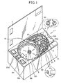
Fig. 1 is a perspective view showing an endoscope washer disinfector according to a first embodiment of the present invention, in which a tray with a used endoscope mounted is loaded into a washing disinfecting bath of the washer disinfector; -
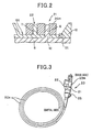
Fig. 2 is a partial sectional view taken along a II - II line shown inFig. 1 ; -
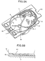
Fig. 3 is a perspective view showing the endoscope to be accommodated in the washing disinfecting bath; -
Fig. 4 is a perspective view showing the tray to be loaded into the washing disinfecting bath; -
Fig. 5A is a perspective view showing the washing disinfecting bath; -
Fig. 5B is a partial sectional view that explains a structure to orient the direction of the endoscope; -
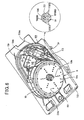
Fig. 6 is a perspective view showing a tray and a washing disinfecting bath unit of the endoscope washer disinfector according to a second embodiment of the present invention; -
Fig. 7 is a partial sectional view taken along a VII - VII line shown inFig. 6 ; -
Fig. 8 is a perspective view showing the endoscope to be accommodated in the washing disinfecting bath in the second embodiment; -
Fig. 9 is a perspective view showing the tray to be loaded into the washing disinfecting bath in the second embodiment; -
Fig. 10 is a perspective view showing only the washing disinfecting bath unit in the second embodiment; -
Fig. 11 is a partial sectional view that explains the connection between the mouth ring and the supply nozzle in another embodiment of the present invention; -
Figs. 12 and 13 are other partial sectional views that explain the connection of the mouth ring and the supply nozzle shown inFig. 11 ; -
Figs. 14 and15 are partial sectional views that explain the connection between the mouth ring and the supply nozzle in another embodiment of the present invention; -
Fig. 16 is a partial perspective view showing how a supply nozzle is connected to the mouth ring in another embodiment of the present invention; -
Fig. 17 is a partial side view showing where positioning through-holes are formed in a modification; and -
Fig. 18 is a sectional view showing how positioning pins touch the wall of a positioning through-hole. - With reference to the accompanying drawings, preferred embodiments of the drawings will now be described.
- Referring to
Figs. 1 - 5A and5B , an endoscope washer disinfector according to a first embodiment of the present invention will now be described. In the following, detailed descriptions will be given to major components of the features of the present invention, while descriptions to the other parts are either simplified or outlined. - As shown in
Fig. 1 , there is provided anendoscope washer disinfector 1 for washing and disinfecting a usedendoscope 20 and accessories thereof. Theendoscope washer disinfector 1 is equipped, as its major components, with amain body 2 and acover 3 which can open and close the top of themain body 2 by for example hinges fixed to an edge of the top. - At a top part of the
main body 2, a washing disinfectingbath unit 50 is arranged to provide a washing disinfecting bath S. Thisbath 5 has a given depth as illustrated inFig. 5A and has an opening facing upward, through which anendoscope 20 is inserted and removed. Atray 10, on which anendoscope 20 is placed to be held thereon as shown inFig. 4 , is detachable to and from thewashing disinfecting bath 5. - In the
main body 2, as shown inFig. 1 , a not-shown fluid supply unit is placed to automatically supply various types of fluid, such as liquid (including washing liquid, disinfectant liquid, and rinsing water) and gas (including air), to each duct (called "channel") of anendoscope 20 accommodated within thewashing disinfecting bath 5. The fluid supply unit comprises anozzle 31 to supply such a fluid and is located outside thewashing disinfecting bath 5 so that thenozzle 5 is directed toward thebath 5. - In the
endoscope 20, there are formed various ducts (i.e., channels) which include an air-supply water-supply duct, a forward water-supply duct, and a therapeutic-instrument insertion duct serving a suction duct as well. In the present embodiment, of those various types of ducts, thenozzle 31 will now be explained as a nozzle member to automatically supply fluid into the therapeutic-instrument insertion duct. Thenozzle 31 is structured to be automatically connected with a mouth ring (mouth piece) 25 (refer toFig. 3 ) of the therapeutic-instrument insertion duct, which is also known. In addition, the structure of the fluid supply unit is known. Those known structures will be omitted from the following explanations. - As shown in
Fig. 5A , thewashing disinfecting bath 5 has a bottom 5t, in which there is formed adrain outlet 5h to drain away, from thewashing disinfecting bath 5, various types of fluid such as washing liquid, disinfectant liquid and rinsing water at a central part of the bottom of the bath. Further, on the bottom 5t, there are formed plurallinear grooves 7 which serve as locating means for thetray 10. Thesegrooves 7 extend substantially radially along the face of the bottom. - The
plural grooves 7 guide the liquid in thewashing disinfecting bath 5 to thedrain outlet 5h. In addition, theplural grooves 7 function to decide the loading direction of thetray 10 relative to thewashing disinfecting bath 5. That is, plural tubular convex parts PT are formed on the rear face of the tray 10 (refer toFig. 5B ). The convex parts PT can be fit into thegrooves 7, when thetray 10 is loaded into thewashing disinfecting bath 5, so that thetray 10 can be oriented automatically in the bath. - To be specific, the directions of the
plural grooves 7 are designed such that a fluid-supply-nozzle insertion opening 13 (later described) (hereinafter simply referred to as an "insertion opening") of thetray 10 is located at a position where asupply nozzle 31 exists. Namely, theendoscope 20 has a manipulatingdevice 20m and amouth ring 25 located and formed on the manipulatingdevice 20 and connected to the therapeutic-instrument insertion duct passing through thedevice 20m, as shown inFig. 3 . Hence theplural grooves 7 decide the loading direction of thetray 10 in a manner that the manipulatingdevice 20m of theendoscope 20 accommodated in thetray 10 approaches thesupply nozzle 31 and themouth ring 25 thereof is located at a position, where thesupply nozzle 31 can be connected automatically with themouth ring 25. - At a position in the bottom 5t of the
washer disinfector 5, afirst positioning pin 6, which is thin and cylindrical, stands up. The pin position is adjacent to one of thegrooves 7, which approaches thesupply nozzle 31. - When the
tray 10 which accommodates theendoscope 20 is loaded into thewashing disinfecting bath 5, thefirst positioning pin 6 is fit into a first through-hole 21 (later described) formed at theendoscope 20 in a manner that all the circumferential surface of thefirst positioning pin 6 comes closely in contact with the first through-hole 21. This fitting operation allows theendoscope 20 to be located to thewashing disinfecting bath 5. Furthermore, thefirst positioning pin 6 is made to penetrate through a first positioning-pin insertion hole 12 (refer toFig. 4 ) formed in thetray 10, which will also be described later. This operation allows thetray 10 to be located to thewashing disinfecting bath 5. - Concretely, the
first positioning pin 6 has the capability to position both thetray 10 and theendoscope 20. In other words, by thefirst positioning pin 6, theendoscope 20 is arranged such that the manipulatingdevice 20m of theendoscope 20 is made to approach the supply nozzle to have themouth ring 25 thereof located at the automatic connection position facing thesupply nozzle 31. - As shown in
Fig. 4 , thetray 10 is detachable from thewashing disinfecting bath 5 and theendoscope 20 can be accommodated and removed into and from thetray 10. Thetray 10 has an outer contour of size almost the same as that of the inner contour of thewashing disinfecting bath 5, when being viewed vertically to the bath. Thetray 10 is formed into a top-face-open case that comprises a side wall (plane) 10g standing up at from the surrounding edge of thebase 10t. - On one side of the
side wall 10g which faces thesupply nozzle 31, aninsertion opening 13 is located which allows thesupply nozzle 31 to be inserted therethrough and which faces themouth ring 25 of theendoscope 20 accommodated in thetray 10. - Furthermore, the bottom 10t of the
tray 10 has a rear side, which faces thewashing disinfecting bath 5 when thetray 10 is loaded into thebath 5. On the rear side, the foregoing plural tubular convex parts PT (refer toFig. 5B ) are formed to be fit into the grooves of thebath 5. The tubular convex parts PT are not limited in their shape to the one described. An alternative example is that each convex part is composed of a plurality of locally protruded parts which form a line. - The
endoscope 20 has, as its essential components, a thin and longflexible insertion tube 20s and a manipulatingdevice 20m (refer toFig. 3 ) integral with the insertion tube. Theendoscope 20 is accommodated in thetray 10 in its rounded and wound attitude of theinsertion tube 20s. Thetray 10 provides a circular insertion-tube accommodation space 10s, in which theinsertion tube 20s of theendoscope 20 can be accommodated, and a manipulating-device accommodation space 10m, in which the manipulatingdevice 20m is accommodated (refer toFig. 3 ). Thetray 10 further provides a remote-control accommodation space 10r, in which a remote control can be accommodated. This remote control is used for manipulating theinsertion tube 20s equipped with a bendable portion bendable using electronic power. - In a central part of the insertion-
tube accommodation space 10s, there is formed adrain port 10h to drain away fluid, such as washing liquid, disinfectant liquid, rising water, and alcohol, to the outside thereof. - As described, in the manipulating-
device accommodation space 10m, theinsertion opening 13 is formed at theside wall 10g. In addition, on the bottom of thataccommodation space 10m, there is the first positioning-pin insertion hole 12 through which thefirst positioning pin 6 is inserted, when thetray 10 is loaded into thewashing disinfecting bath 5. - The first positioning-
pin insertion hole 12 is formed to have a contour which is tightly in contact with the whole periphery of thefirst positioning pin 6. Thisinsertion hole 12 is located to positionally correspond to the position of thefirst positioning pin 6 when thetray 10 is loaded into thewashing disinfecting bath 5. - In the manipulating-
device accommodation space 10m, a cylindricalsecond positioning pin 11 is formed to stand up from the bottom 10t. The position of thissecond positioning pin 11 is close to the first positioning-pin insertion hole 12. - As shown in
Fig. 2 , in cases where the manipulatingdevice 20m is accommodated in the manipulating-device accommodation space 10m, thesecond positioning pin 11 can be fitted into a later-described second through-hole 22 formed at theendoscope 20. Actually this insertion is carried out such that the entire periphery of thissecond positioning pin 11 closely contacts the second through-hole 22, thus enabling theendoscope 20 to be located relative to thetray 10. - Practically, the
second positioning pin 11 is located so that the mouth ring 25 (refer toFig. 3 ) of theendoscope 20 accommodated in thetray 10 is opposite to theinsertion opening 13. According to this, when thetray 10 is loaded into thewashing disinfecting bath 5, thesecond positioning pin 11 locates theendoscope 20 in thetray 10 such that themouth ring 25 is fixed at the automatic connection position where thesupply nozzle 31 directly faces themouth ring 25. - As shown in
Fig. 3 , the manipulatingdevice 20m of theendoscope 20 has the first through-hole 21, which is a positioning through-hole through which thefirst positioning pin 6 is tightly inserted, and the second through-hole 22, which is a positioning through-hole through which thesecond positioning pin 11 is tightly inserted. - The first through-
hole 21 and the second through-hole 22 have diameters so that the though-holes - Each of the first and second through-
holes - As shown in
Fig. 3 , themouth ring 25, which communicates with the therapeutic-instrument insertion duct, is mounted on the manipulatingdevice 20m to be oblique by a given angle to an axis along the manipulatingdevice 20m. - The operations and advantages of the endoscope washer disinfector according to the present embodiment will now be described.
- For using the endoscope washer disinfector to wash and disinfect a used
endoscope 20, the usedendoscope 20 is first accommodated into thetray 10, before thetray 10 is loaded into thewashing disinfecting bath 5. Concretely theinsertion tube 20s is wound as illustrated inFig. 3 , and accommodated in the insertion-tubeaccommodating space 10s, as illustrated inFig. 1 , during which time the manipulatingdevice 20m is placed into the manipulating-deviceaccommodating space 10m. - When the manipulating
device 20m is accommodated into thespace 10m, thesecond positioning pin 11 standing up from the bottom 10t of thespace 10m is tightly fit into the second through-hole 22 formed through the manipulatingdevice 20m, as shown inFigs. 1 and2 . As a result of this accommodation, theendoscope 20 in the tray is located to thetray 10 so that themouth ring 25 is opposite to theinsertion opening 13 of thetray 10. - As described above, the remote control is also accommodated into the remote-
control accommodation space 10r of thetray 10. - Then the
tray 10, in which theendoscope 20 is secured, is carried to theendoscope washer disinfector 1, and then loaded into thewashing disinfecting bath 5. This loading action is performed as follows. The tubular convex parts PT formed on the rear side of the bottom 10t (i.e., mounting plane) of thetray 10 are fitted into thegrooves 7 formed on the bottom 5t of thewashing disinfecting bath 5 so that thetray 10 is oriented firmly. Concurrently with this fitting action, as shown inFigs. 1 and2 , the first positioning-pin insertion hole 12 of thetray 10 accepts the insertion of thefirst positioning pin 6 standing up from the bottom 5t. Further, concurrently with the fitting action, the first through-hole 21 of the manipulatingdevice 20m accepts tight insertion of thefirst positioning pin 6, before completion of loading thetray 10 with the usedendoscope 20 to thewashing disinfecting bath 5. - As a result, a combination of the
plural grooves 7 and thefirst positioning pin 6 allows the manipulatingdevice 20m to be located close to thesupply nozzle 31. By this close location, themouth ring 25 of theendoscope 20 is present at the automatic connection position which is directly opposed to thesupply nozzle 31, resulting in that theendoscope 20 is ready for washing and disinfection at the given position. - In this way, the
endoscope 20, which is accommodated in thetray 10, is also accommodated and located with precision in thewashing disinfecting bath 5. Then thetop cover 3 is closed on themain body 2, and theendoscopic washer disinfector 1 is switched on. In response to this action, thesupply nozzle 31 is moved the automatic connection position, where thenozzle 31 is automatically connected with themouth ring 25 that has been located in front of thesupply nozzle 31. This loading action is followed by supplying various types of fluid into the therapeutic-instrument insertion duct via themouth ring 25 during each of the processing steps for washing and disinfection of theendoscope 20. - In the present embodiment, the
plural grooves 7 are formed on the bottom 5t of thewashing disinfecting bath 5 to orient thetray 10 to the given loading direction in thebase 5. In addition, the manipulatingdevice 20m of theendoscope 20 has the first through-hole 21 through which thefirst positioning pin 6 is fit for fixedly positioning both thetray 10 and theendoscope 20 relative to thebath 5. - Further, on the bottom 10t of the manipulating-
device accommodation space 10m of thetray 10, the first positioning-pin insertion hole 12 accepts the insertion of thefirst positioning pin 6 therethrough. At the same time, the second through-hole 22 of the manipulatingdevice 20m accepts the insertion of thesecond positioning pin 11 so that theendoscope 20 is securely fixed relative to thetray 10. - Accordingly, when the
endoscope 20 is accommodated into thetray 10, thesecond positioning pin 11 is inserted into the second through-hole 22. This inserting action makes it possible to position theendoscope 20 relative to thetray 10 such that itsmouth ring 25 is in front of theinsertion opening 13. - Moreover, the
first positioning pin 6 is inserted into the first positioning-pin insertion hole 12 to cause thepin 6 to penetrate through the first through-hole 21. And theplural grooves 7 formed on the bottom 5t of thebath 5 are subjected to tight insertion of the tubular convex parts PT in a very simple manner. This insertion action makes it possible to position both thetray 10 and theendoscope 20 relative to thewashing disinfecting bath 5. That is, thesupply nozzle 31 is automatically placed at the automatic connection position, at which thesupply nozzle 31 is movable toward theinsertion opening 13. That is, the manipulatingdevice 20m is located close to thesupply nozzle 31 to permit themouth ring 25 to be present at the automatic connection position. - Therefore, in the present
endoscope washer disinfector 1, when thetray 10 is used to position the usedendoscope 20 in thewashing disinfecting bath 5, the user's operations to locate itsmouth ring 25 to thesupply nozzle 31 can be simplified, but still performed at high precision. - The foregoing loading operations and advantages resultant therefrom will not be limited to the therapeutic-instrument insertion duct of the
endoscope 20, but are true of the other ducts. In the same manner as that described above, supply nozzles can be coupled to mouth rings mounted to open from the manipulating device at one end of each of the other ducts. - Some other modifications can be provided as follows. Unlike the present embodiment where the
plural positioning grooves 7 extend from thedrain port 5h almost radially on the bottom 5t, some other extending patterns can be adopted. The radial-pattern grooves may be dedicated to guide the various types of fluid to thedrain port 5h in thebath 5 and, separately from the grooves, another groove for positioning thetray 10 to thebath 5 may be formed on the bottom 5t. Alternatively, the grooves may be consistent in their arrangement with the contour of the bottom 10t of thetray 10 providing the mounting plane, still providing advantages similar to the foregoing. - Moreover, the present embodiment adopts a wholly mutual-contacted manner between the
first positioning pin 6 and the first through-hole 21 and a wholly tightly contacted manner between thesecond positioning pin 11 and the second through~hole 22. However, this is just an example. If theendoscope 20 is positionally stationary after the pin insertion, it is possible to adopt a partly mutual-contacted manner between each pin and each through-hole. For example, a cross section of each pin, which is perpendicular to the axis thereof, should not be limited to be circular. Each of the positioning pins 6 and 11 may be produced to have another cross section which partly touches the inner surface of each of the through-holes - Referring to
Figs. 6 - 10 , an endoscope washer disinfector according to a second embodiment of the present invention will now be described. - Compared to the
endoscope washer disinfector 1 according to the first embodiment, the endoscope washer disinfector according to this second embodiment is different in that the first positioning pin and the second positioning pin are placed concentrically in the insertion direction. The other components are the same or similar as or to that of the first embodiment, so that those components are given the same reference numerals as those in the first embodiment for omitting those components. Only different components will now be described. - As shown in
Fig. 10 , afirst positioning pin 106 is placed to be close to one of thegrooves 7, which is in proximity to thesupply nozzle 31, so that thepin 106 stands up from the bottom 5t of thewashing disinfecting bath 5. The plan view of thefirst positioning pin 106 is cruciform, which consists of four blade members 106BD. InFig. 10 , thefirst positioning pin 106 stands up at a position different from that of thefirst positioning pin 6 in the first embodiment, but may be designed to stand up at the same position as that in the first embodiment. - As shown in
Figs. 6 and7 , thefirst positioning pin 106 is in charge of not only positioning theendoscope 20 relative to thewashing disinfecting bath 5 but also positioning thetray 10 relative to thebath 5, when thetray 10 with theendoscope 20 accommodated therein is loaded into thebath 5. The former positioning is achieved by having thefirst positioning pin 106 fit into a third though-hole 23 (later described) formed through theendoscope 20, in which thepin 106 is partly touched to the inner wall of the third through-hole 23. That is, the radial end faces of the four blade members 106BD are made to touch the third through-hole 23. Meanwhile, the latter positioning is achieved by having thefirst positioning pin 106 fit into a first positioning-pin insertion hole 112 (later described) formed through thetray 10, in which thepin 106 is partly touched to the inner wall of theinsertion hole 112. - Practically, the
first positioning pin 106 positions both thetray 10 and theendoscope 20 such that the manipulatingdevice 20m of theendoscope 20 is located close to thesupply nozzle 31 at an automatic connection position, where themouth ring 25 thereof is directly opposed to thesupply nozzle 31 and may be automatically connected with thesupply nozzle 31. -
Fig. 9 shows the bottom 10t of the manlpulating-device accommodation space 10m of thetray 10. On the bottom 10t, the first positioning-pin insertion hole 112 is located, through which thefirst positioning pin 106 is formed to be inserted when thetray 10 is loaded into thewashing disinfecting bath 5. - The first positioning-
pin insertion hole 112 is produced to have a diameter which allows thefirst positioning pin 106 to partly touch the wall of thishole 112. In addition, thishole 112 is located face to face with thefirst positioning pin 106, when thetray 10 is loaded into thewashing disinfecting bath 5. - Furthermore, on the bottom 10t of the manipulating-
device accommodation space 10m, asecond positioning pin 111 is fixed at a position to stand up thereat. The position of thispin 111 is decided so as to avoid, in the plane of the bottom 10t, an interference with thefirst positioning pin 106, in cases where thepin 106 is inserted into the first positioning-pin insertion hole 112. Thesecond positioning pin 111 is shaped into a cross shape consisting of four blade members 111BM, but with no central part, which protrudes along four radial directions within the first positioning-pin insertion hole 112, when viewed vertically as shown inFig. 6 . - The
second positioning pin 111 is located to become concentric with thefirst positioning pin 106 as to their central axes, whenever thetray 10 is loaded into thewashing disinfecting bath 5. - When the manipulating
device 20m is placed into the manipulating-device accommodation space 10m, thesecond positioning pin 111 is forcibly inserted into the third through-hole 23 formed through theendoscope 20, as shown inFigs. 6 and7 . In this inserted state, part of the pin 111 (i.e., the radial end faces of the four blade members 111BM) is made to touch the wall of the third through-hole 23, providing theendoscope 20 with a positioning function to thetray 10. - To be specific, the
second positioning pin 111 positions theendoscope 20 such that themouth ring 25 thereof is opposed to theInsertion opening 13. As a result, whenever thetray 10 is loaded into thewashing disinfecting bath 5, themouth ring 25 is located at the automatic connection position, where themouth ring 25 is directly opposite to thesupply nozzle 31. -
Fig. 8 shows the manipulatingdevice 20m of theendoscope 20, in which the third through-hole 23 is formed through thedevice 20m and serves as a positioning hole which allows both the first and second positioning pins 106 and 111 to be inserted forcibly therethrough. - Incidentally, the third through-
hole 23 has a diameter which allows the first and second positioning pins 106 and 111 to be partly in contact with the wall of the third through-hole 23. Further, the third through-hole 23 may be formed as a bottomed hole. - The operations and advantages of the second embodiment will now be described.
- Similarly to the case in the first embodiment, for washing and disinfecting a used
endoscope 20, theendoscope 20 is first accommodated in thetray 10, prior to loading thetray 10 into thewashing disinfecting bath 5. Practically, as shown inFig. 8 , theinsertion tube 20s is wound, earlier, as shown inFig. 6 , being accommodated into the insertion-tube accommodation space 10s. Then themanipulation device 20m is accommodated into the manipulating-device accommodation space 10m. - In accommodating the manipulating
device 20m into theaccommodation space 10m, thesecond positioning pin 111 is forcibly inserted into the third through-hole 23 of the manipulatingdevice 20m in a party-contacted manner with the wall of this through-hole 23, as shown inFigs. 6 and7 . Since thesecond positioning pin 111 stands up from the bottom 10t of the manipulating-device accommodation space 10m, themouth ring 25 is located facing theinsertion opening 13. In this state, theendoscope 20 is positioned relative to thetray 10. - The remote control is also accommodated in the remote-
control accommodation space 10r of thetray 10. - Next the
tray 10 with theendoscope 10 mounted therein is loaded into thewashing disinfecting bath 5. That is, as described, the plural tubular convex parts PT on the bottom 10t of the rear side of thetray 10 are fitted into theplural grooves 7 on the bottom 5t of thebath 5. In parallel with this, as shown inFigs. 6 and7 , thefirst positioning pin 106 standing up from the bottom 5t of thebath 5 is inserted into the first positioning-pin insertion hole 112 of thetray 10 in a manner that thepin 106 does not touch thesecond positioning pin 111. In addition, thepin 106 is inserted into the third through-hole 23 of the manipulatingdevice 20m in a manner that thepin 106 partly touches the third through-hole 23. - As a result, the
plural grooves 7 and thefirst positioning pin 106 allow themouth ring 25 to be located at the automatic connection position facing thesupply nozzle 31, like the case in the first embodiment. - Accordingly, the
endoscope 20 accommodated in thetray 10 can be accommodated in thebath 5 with high accuracy. Thetop cover 3 is then closed, thewasher disinfector 1 is switched on, so that thesupply nozzle 31 is moved toward themouth ring 25 of theendoscope 20 for automatic connection therewith. Various kinds of fluids are supplied into the therapeutic-instrument insertion duct via themouth ring 25 from thesupply nozzle 31 during the washing and disinfecting processes. - In this way, using the third through-
hole 23 which accepts the insertion of thefirst positioning pin 106 in a partly touched manner to the through-hole 23, both thetray 10 and theendoscope 20 are positioned relative to thewashing disinfecting bath 5 at the same time. - Also, used are the first positioning-
pin insertion hole 112 which accepts thefirst positioning pin 106 and the third through-hole 23 which accepts thesecond positioning pin 111 in a partly-touched manner with the through-hole 23, in which bothpins second positioning pin 111 is able to position theendoscope 20 relative to thetray 10. - Hence, advantages similar to those in the first embodiment can be obtained. Additionally there is another advantage resulting from the structure in which both of the first and second positioning pins 106 and 111 are partly touched to the third through-
hole 23. Thanks to such structures, various kinds of fluids for washing and disinfection can be circulated through the gaps formed between the positioning pins 106 and 111 and the through-hole 23. Although such gaps are subjected to accumulation of dirt, circulating the fluid will surely increase the washing and disinfecting performance for theendoscope 20. - The foregoing operations are true of the ducts of the
endoscope 20 other than therapeutic-instrument insertion duct, providing similar advantages to the above. - In the present embodiment, some other modifications can be provided as follows. Unlike the present embodiment where the
plural positioning grooves 7 extend from thedrain port 5h almost radially on the bottom 5t, some other extending patterns can be adopted. The radial-pattern grooves may be dedicated to guide the various types of fluid to thedrain port 5h in thebath 5 and, separately from the grooves, another groove for positioning thetray 10 to thebath 5 may be formed on the bottom 5t. Alternatively, the grooves may be consistent in their arrangement pattern with the contour of the bottom 10t of thetray 10 providing the mounting plane, still providing advantages similar to the foregoing. - By the way, some cases may arise where, when the
tray 10 with theendoscope 20 mounted therein is loaded into thebath 5, themouth ring 25 of the manipulatingdevice 20m may slightly shift from the automatic connection position even if the structures according to the first or second embodiment are employed. In the following, the structure will now be described which allows thesupply nozzle 31 to be connected with themouth ring 25 more reliably, even when such a positional shift happens. -
Fig. 11 shows aconnection end 31v attached to thesupply nozzle 31. Thisconnection end 31v covers the outer circumferential surface of themouth ring 25 of theendoscope 20. Theconnection end 31v has a tapered innercircumferential surface 32 formed such that the diameter of the opening gradually becomes smaller as the distance advances inside along the axial direction from the end thereof. - Thus, when being connected to the
mouth ring 25 automatically by a known automatic electrical mechanical mechanism (not shown), a ring-shapedtip 25s of themouth ring 25 is made to touch the innercircumferential surface 32 of theconnection end 31v, as shown inFig. 13 . Theconnection end 31v is equipped with a ring-shapedelastic member 33 made of, for example, rubber. Thismember 33 is positionally consistent with the ring-shapedtip 25s, when being connected completely. Theconnection end 31v is made of self-lubricating material such as plastic resin including polyacetal resin. - Hence, even if the
mouth ring 25 is positionally deviated from thesupply nozzle 31 by an amount X1 as illustrated inFig. 11 , the mutual relative positions of both themouth ring 25 and theconnection end 31v are corrected during the travel of thesupply nozzle 31. The reason is that, as shown inFig. 12 , the ring-shapedtip 25s which has contacted the tapered innercircumferential surface 32 of theconnected end 31v is contacting a self-lubricating surface. Hence both thesupply nozzle 31 and themouth ring 25 are mutually guided to make theirfluid supply paths Fig. 13 . That is, both central axes of thefluid supply paths - When the connection is completed, the ring-shaped
tip 25s of themouth ring 25 forcibly presses theelastic member 33, theconnection end 31v is connected with themouth ring 25 to cover the ring-shapedtip 25s as shown inFig. 13 , providing a watertight communication between bothfluid supply paths - Hence, even if the
tray 10 is loaded into thebase 5 and causes a situation where themouth ring 25 is positionally shifted from thesupply nozzle 31, i.e., the automatic connection position, the tapered innercircumferential surface 32 corrects the mutual positions within a design allowance. It is therefore possible to load thesupply nozzle 31 to themouth ring 25 more reliably. - Of course, the above structure of the
supply nozzle 31 can be applied to mouth rings other than themouth ring 25 of the therapeutic-instrument insertion duct, still providing the same position-correcting advantage. - Referring to
Figs. 14 and15 , a modification showing another connection method between the supply nozzle and the mouth ring will now be described. -
Fig. 14 shows asupply nozzle 31 with aconnection end 31w to be fitted into themouth ring 25 of theendoscope 20 during the automatic connecting procedure. Theconnection end 31w has a tapered outercircumferential surface 34 the diameter of which becomes larger as the distance advances inside along the axial direction from the end thereof. - The
connection end 31w has a part on its outercircumferential surface 34, which touches the ring-shapedtip 25s of themouth ring 25 when the connection is completed. Anelastic member 35, such as rubber, is arranged on that part of thesurface 34. Theconnection end 31w is made of self-lubricating material such as such as plastic resin including polyacetal resin. - Thus, as shown in
Fig. 14 , when a positional difference X2 between themouth ring 25 and thesupply nozzle 31 is caused during movement of thesupply nozzle 31, the outercircumferential surface 34 is able to provide a positional correction function because of a combination of its tapered surface and its self-lubricating property. The mutual relative positions between bothfluid supply paths supply nozzle 31 and themouth ring 25 are corrected automatically during the travel of thesupply nozzle 31, as shown inFig. 15 . - When the connection is completed, the ring-shaped
tip 25s of themouth 25 forcibly presses theelastic member 35, providing a watertight communication between thefluid supply paths - Hence the
supply nozzle 31 shown inFig. 14 has the capability of automatically correcting the mutual relative positional difference within a given allowable margin, so that thesupply nozzle 31 can be watertight-connected to themouth ring 25 more reliably. - The above structure of the
supply nozzle 31 can also be applied to mouth rings other than themouth ring 25 of the therapeutic-instrument insertion duct, still providing the same position-correcting advantage. - Referring to
Fig. 16 , a further embodiment will now be described. This embodiment also concerns a modification of the supply nozzle, which is able to prevent the supply nozzle from shifting from the automatic connection position. -
Fig. 16 shows anozzle support member 90 that supports asupply nozzle 80 on atray 60. This example shows an example in which thesupply nozzle 80 is detachably connected with amouth ring 29 extended from the end of, for example, an air-supply water-supply duct of theendoscope 20. That is, themouth ring 29 is located on thebase end 20t of the manipulatingdevice 20m of theendoscope 20. - There is a fluid supply unit (not shown) equipped with the
elongated supply nozzle 80 oriented to thewashing disinfecting bath 5, as shown inFig. 16 . - The
tray 60 has aside wall 60g, which faces thesupply nozzle 80 when thetray 60 is loaded into thebath 5. Theside wall 60g has aninsertion opening 60h though which thesupply nozzle 80 passes. Between theinsertion opening 60h and themouth ring 29 of the air-supply water-supply duct, anozzle support member 90 fixedly stands up from the bottom 60t of thetray 60. Thenozzle support member 90, which has a surface that is curved according to the curvature of the outer circumferential surface of thesupply nozzle 80, is in charge of supporting thesupply nozzle 80 so that thenozzle 80 keeps its position facing themouth ring 29 without any positional shift. Thenozzle support member 90 may be placed on the bottom 5t of thebath 5. - Components other then the
bath 5 andtray 60 are the same as those in described already. - In this way, the
nozzle support member 90 is arranged to support the given circumferential angular range of thesupply nozzle 80, with the result that thesupply nozzle 80 is prevented from shifting from the automatic connection position. Hence it is possible to provide a stable and reliable connection of thesupply nozzle 80 to themouth ring 29, even if thesupply nozzle 80 has an elongated outer shape. - The above
nozzle support member 90 may also be applied to other mouth rings for the therapeutic-instrument insertion duct and others and is able to provide equivalent advantages to the above. - According to the present invention, various modifications can also be provided.
- A first modification exemplifies how to decide the orientation of the
tray 10 relative to thewashing disinfecting bath 5. In the foregoing embodiments, the plural tubular convex parts PT are formed on the rear side of the bottom 10t (serving as an endoscope mounting plane) of thetray 10, while the plurallinear grooves 7 into which the tubular convex parts PT are fit are formed on the bottom 5t of thebase 5. In contrast, this concave-convex relationship may be formed in the opposite manner. In other words, the liner grooves may be formed on the rear side of the bottom of thetray 10, and the tubular convex parts may be formed on the bottom 5t of thebath 5. - A second modification concerns the positioning through-hole (21, 22; 23) which is formed at the manipulating
device 20m and which serves as a latching part to position the manipulatingdevice 20m to thetray 10 and thewashing disinfecting bath 5. - It is not always necessary to produce this positioning through-hole at the main body itself of the manipulating
device 20. For example, as shown inFig. 17 , a protrudingportion 20n is integrally added to, for example, a distal-side part of the manipulatingdevice 20m and such a positioning through-hole is formed through the added protrudingportion 20n. The example shown inFig. 17 provides the positioning through-holes device 20m, the present invention can be put into practice without changing or re-designing the internal structure itself of thisdevice 20m. - A third modification concerns another way of making the first and second positioning pins 106 and 111 touch the circumferential wall surface of the poisoning through-
hole 23, that is, a modification from the second embodiment. - In the second embodiment, each of the positioning pins 106 and 111 is formed to have radially-extended arm portions each having a specified, but limited, area on the radially-directed tip face thereof. The specified area enables each of the
pins hole 23 with planar contact. In contrast, as shown inFig. 18 , the modification exemplifies a first positioning pin 106' and a second positioning pin 111' which are able to touch the through-hole 23 with line contact or point contact. This is because each of the positioning pins 106' and 111' is formed to have radially-extended arm portions each having a pointed radially-directed tip. The pointed tips enable each of the pins 106' and 111' to touch the through-hole 23 with line or point contact. Thus hardly any substance or dirt can remain between the wall surface of the positioning through-hole 23 and the positioning pins 106' and 111', enhancing the washing and disinfection effect. - Although the description above contains many specificities, these should not be construed as limiting the scope of the invention but as merely providing illustrations of some of the presently preferred embodiments of the present invention. Thus the scope of the present invention should be determined by the appended claims.
Claims (15)
- An endoscope washer disinfector (1) for washing and disinfecting an endoscope (20) equipped with a mouth ring (25) communicating with a duct formed within through the endoscope, comprising:a washing disinfecting bath (5) in which the endoscope is accommodated;a nozzle (31) arranged with the washing disinfecting bath, loaded into the mouth ring of the endoscope, and is in charge of supplying fluid to the duct via the mouth ring;a tray (10) on which the endoscope is mounted and which is detachably loaded into the washing disinfecting bath;a bilateral positioning member (11, 22; 23, 111, 112) that positions the endoscope and the tray so that the mouth ring of the endoscope mounted on the tray is located at a given position on the tray; anda trilateral positioning member (12, 6, 21; 23, 106) that positions the washing disinfecting bath, the tray, and the endoscope so that, when the tray is loaded into the washing disinfecting bath, the mouth ring of the endoscope positioned at the given position on the tray by the bilateral positioning member is positioned at a position that is across from the nozzle.
- The endoscope washer disinfector of claim 1, comprising
a direction deciding member (PT, 7) that decides a loading direction of the tray such that the tray loaded into the washing disinfecting bath is positioned in a given direction on which the mouth ring is positioned relative to the nozzle. - The endoscope washer disinfector of claim 2, wherein the bilateral positioning member is provided with a latch portion (22) formed at a given position of the endoscope and a pin (11) that stands up from the tray and engages with the latch portion when the endoscope is mounted on the tray.
- The endoscope washer disinfector of claim 3, wherein
the given position of the endoscope exists at a manipulating device to manually manipulate the endoscope,
the latch portion is a positioning through-hole (22) formed through the manipulating device, the pin (11) being fit into the positioning through-hole with the pin touched, at least partly, to the positioning through-hole when the endoscope is mounted on the tray. - The endoscope washer disinfector of claim 2, wherein the trilateral positioning member (12, 6, 21) is provided with
a latch portion (21) formed at a given position of the endoscope,
a further latch portion (12) formed at a given position on the tray, the endoscope being mounted at the given position on the tray, and
a pin (6) that stands up from the washing disinfecting bath and engages with both the latch portion (21) and the further latch portion (12) when the tray with the endoscope mounted thereon is loaded into the washing disinfecting bath. - The endoscope washer disinfector of claim 5, wherein
the given position of the endoscope exists at a manipulating device to manually manipulate the endoscope,
the latch portion (21) is a positioning through-hole (21) formed through the manipulating device,
the further latch portion (12) is an insertion hole (12) formed through the tray,
wherein the pin (6) is fit into the insertion hole (12) with the pin touched, at least partly, to the insertion hole (12) and the pin (6) is fit into the positioning through-hole (21) with the pin touched, at least partly, to the positioning through-hole (21), when the tray with the endoscope mounted thereon is loaded into the washing disinfecting bath. - The endoscope washer disinfector of claim 2, wherein direction deciding member includes a groove formed on the washing disinfecting bath and a convex part formed on the tray to be fit into the groove.
- The endoscope washer disinfector of claim 7, wherein
the groove consists of a plurality of grooves radially extending from a central part of a bottom of the washing disinfecting bath, and
the convex part includes a plurality of tubular convex parts which are allowed to be fit into the plurality of grooves when the tray is loaded into the washing disinfecting bath. - The endoscope washer disinfector of claim 1, wherein
the bilateral positioning member (11, 22) includes a positioning through-hole (22) for positioning the mouth ring at the given position on the tray and the trilateral positioning member (12, 6, 21) includes a positioning through-hole (21) for positioning the mouth ring at the given position on the tray, and the positioning through-hole (21) of the bilateral positioning member being different from the positioning through-hole (22) of the trilateral positioning member. - The endoscope washer disinfector of claim 1, wherein
the bilateral positioning member (11, 22; 23, 111, 112) and the trilateral positioning member (12, 6, 21; 23, 106) include a positioning through-hole (23) used to position the mouth ring at the given position on the tray and used in common for both the bilateral and trilateral positioning members,
the bilateral positioning member (11, 22; 23, 111, 112) includes a first positioning pin (111) standing up from the tray and latching with the common positioning through-hole (23) and an insertion through-hole (112) formed at the standing-up position of the first positioning pin (111) so as to avoid the first positioning pin, and
the trilateral positioning member (12, 6, 21; 23, 106) includes a second positioning pin (106) standing up from the washing disinfecting bath and latching with the common positioning through-hole (23) via the insertion through-hole (112) of the bilateral positioning member when the tray is loaded into the washing disinfecting bath. - The endoscope washer disinfector of claim 10, wherein
each of the first positioning pin (111) and the second positioning pin (106) has a plurality of blade parts radially extending in a section perpendicular to a direction along which the first and second positioning pins stand up, and
the plural blade parts of the first positioning pin (111) and the plural blade parts of the second positioning pin (106) extend so as to avoid a positional interference from one the other and touches the common positioning through-hole (23). - The endoscope washer disinfector of claim 11, wherein the plural blade parts of each of the first positioning pin (111) and the second positioning pin (112) touch the common positioning through-hole (23) with point or plane contact.
- The endoscope washer disinfector of claim 1, wherein
the nozzle comprises a connection end (31v, 31w) into which the mouth ring is fit, and
the connection end comprises a mechanism for allowing the fitting action of the nozzle into the mouth ring as a positional error between positions of the mouth ring and the nozzle is absorbed during the fitting action, the positional error being within a given allowable range. - A method of positioning a mouth ring of an endoscope toward a nozzle for supplying fluid, wherein the mouth ring communicates with a duct formed within through the endoscope, the endoscope is mounted on a tray to be loaded into an washing disinfecting bath of an endoscope washer disinfector, and the nozzle is arranged with the washing disinfecting bath, the method comprising steps of:bilaterally positioning the endoscope and the tray so that the mouth ring of the endoscope mounted on the tray is located at a given position on the tray; andtrilaterally positioning the washing disinfecting bath, the tray, and the endoscope so that, when the tray is loaded into the washing disinfecting bath, the mouth ring of the endoscope positioned at the given position on the tray by the bilateral positioning step is positioned at a position that is across from the nozzle.
- The positioning method of claim 14, comprising a step of deciding a loading direction of the tray such that the tray loaded into the washing disinfecting bath is positioned in a given direction on which the mouth ring is positioned relative to the nozzle, the deciding step being carried out in parallel with the trilateral positioning step.
Applications Claiming Priority (1)
| Application Number | Priority Date | Filing Date | Title |
|---|---|---|---|
| JP2006337362A JP2008148763A (en) | 2006-12-14 | 2006-12-14 | Endoscope cleaning disinfection device |
Publications (2)
| Publication Number | Publication Date |
|---|---|
| EP1938742A1 true EP1938742A1 (en) | 2008-07-02 |
| EP1938742B1 EP1938742B1 (en) | 2010-07-28 |
Family
ID=39203299
Family Applications (1)
| Application Number | Title | Priority Date | Filing Date |
|---|---|---|---|
| EP07024318A Not-in-force EP1938742B1 (en) | 2006-12-14 | 2007-12-14 | Washer disinfector equipped with bath to which tray with endoscope mounted thereon is detachably loaded |
Country Status (6)
| Country | Link |
|---|---|
| US (1) | US7918234B2 (en) |
| EP (1) | EP1938742B1 (en) |
| JP (1) | JP2008148763A (en) |
| KR (1) | KR20080055726A (en) |
| CN (2) | CN101204587B (en) |
| DE (1) | DE602007008042D1 (en) |
Families Citing this family (31)
| Publication number | Priority date | Publication date | Assignee | Title |
|---|---|---|---|---|
| JP2008148763A (en) * | 2006-12-14 | 2008-07-03 | Olympus Medical Systems Corp | Endoscope cleaning disinfection device |
| US8468637B2 (en) | 2009-02-06 | 2013-06-25 | Endoclear Llc | Mechanically-actuated endotracheal tube cleaning device |
| EP3329955B1 (en) | 2009-02-06 | 2020-10-21 | Endoclear LLC | Device for cleaning endotracheal tubes |
| US9445714B2 (en) | 2010-03-29 | 2016-09-20 | Endoclear Llc | Endotracheal tube coupling adapters |
| EP2552293B1 (en) | 2010-03-29 | 2015-01-07 | Endoclear LLC | Airway cleaning and visualization |
| US9468696B2 (en) | 2010-09-08 | 2016-10-18 | Pure Processing LLC | Multiple-pump sink insert for cleaning a medical or surgical device |
| US8967168B1 (en) * | 2010-09-08 | 2015-03-03 | Pure Processing LLC | Sink insert for cleaning a medical or surgical device |
| US9676681B2 (en) | 2011-01-19 | 2017-06-13 | Exxonmobil Chemical Patents Inc. | Method and apparatus for managing hydrogen content through the conversion of hydrocarbons into olefins |
| US9346728B2 (en) | 2011-01-19 | 2016-05-24 | Exxonmobil Chemical Patents Inc. | Hydrocarbon conversion process |
| US9708232B2 (en) | 2011-01-19 | 2017-07-18 | Exxonmobil Chemical Patents Inc. | Method and apparatus for converting hydrocarbons into olefins |
| US9708231B2 (en) | 2011-01-19 | 2017-07-18 | Exxonmobil Chemical Patents Inc. | Method and apparatus for converting hydrocarbons into olefins using hydroprocessing and thermal pyrolysis |
| US9815751B2 (en) | 2011-01-19 | 2017-11-14 | Exxonmobil Chemical Patents Inc. | Hydrocarbon and oxygenate conversion by high severity pyrolysis to make acetylene and ethylene |
| US9505680B2 (en) | 2011-01-19 | 2016-11-29 | Exxonmobil Chemical Patents Inc. | Method and apparatus for managing the conversion of hydrocarbons into olefins |
| WO2012099672A2 (en) | 2011-01-19 | 2012-07-26 | Exxonmobil Chemical Patents Nc. | Hydrocarbon conversion process |
| US9809508B2 (en) | 2011-01-19 | 2017-11-07 | Exxonmobil Chemical Patents Inc. | Method and apparatus for converting hydrocarbons into olefins |
| US9677014B2 (en) | 2011-01-19 | 2017-06-13 | Exxonmobil Chemical Patents Inc. | Process and apparatus for converting hydrocarbons |
| US9868680B2 (en) | 2011-01-19 | 2018-01-16 | Exxonmobil Chemical Patents Inc. | Method and apparatus for converting hydrocarbons into olefins |
| JP5572768B1 (en) * | 2012-09-18 | 2014-08-13 | オリンパスメディカルシステムズ株式会社 | Endoscope cleaning disinfection device |
| EP2928517B2 (en) | 2012-12-04 | 2025-08-27 | SunMed Group Holdings, LLC | Suction cleaning devices |
| RU2016150542A (en) * | 2014-05-23 | 2018-06-25 | Медивейторс, Инк. | DISINFECTANT SYSTEM CONNECTORS |
| US10016575B2 (en) | 2014-06-03 | 2018-07-10 | Endoclear Llc | Cleaning devices, systems and methods |
| JP6503332B2 (en) * | 2016-12-22 | 2019-04-17 | 池田機械産業株式会社 | Endoscope purification bag |
| CA3058887A1 (en) * | 2017-04-13 | 2018-10-18 | C.R. Bard, Inc. | Catheter insertion tray with integrated instructions |
| CN107029264B (en) * | 2017-06-14 | 2023-09-12 | 四川大学 | A steam sterilization box |
| CN108079351A (en) * | 2017-12-18 | 2018-05-29 | 广州永士达医疗科技有限责任公司 | A kind of OCT catheter disinfections device |
| CN114532953B (en) * | 2022-02-22 | 2024-06-04 | 上海蒂麦医疗科技有限公司 | Endoscope cleaning device |
| CN115228849B (en) * | 2022-06-23 | 2023-05-26 | 老肯医疗科技股份有限公司 | Full-automatic endoscope multi-cabin cleaning machine |
| CN115399720B (en) * | 2022-09-27 | 2023-06-09 | 淄博金箭医疗器械有限公司 | Soft endoscope lumen cleaning and disinfecting integrated system and method |
| CN116020821B (en) * | 2023-03-30 | 2023-06-06 | 山东东山医疗科技有限公司 | Endoscope disinfection cleaning machine capable of detecting leakage in whole course |
| CN117619770B (en) * | 2023-12-01 | 2024-06-07 | 无锡市博澳智能装备有限公司 | Positioning tray loader for automatically sorting batteries |
| CN119114541B (en) * | 2024-11-15 | 2025-02-28 | 西安医学院第二附属医院 | Cardiology treatment catheter cleaning device |
Citations (5)
| Publication number | Priority date | Publication date | Assignee | Title |
|---|---|---|---|---|
| US20050000553A1 (en) * | 2001-02-28 | 2005-01-06 | Olympus Corporation | High temperature and pressure steam sterilization container for endoscope, and endoscope cleaning and sterilizing device |
| US20050209507A1 (en) * | 2004-03-22 | 2005-09-22 | Olympus Corporation | Endoscope washer system, endoscope washer device, and endoscope |
| JP2006095084A (en) | 2004-09-29 | 2006-04-13 | Olympus Corp | Endoscope |
| EP1785148A2 (en) | 2005-11-11 | 2007-05-16 | Olympus Medical Systems Corp. | Apparatus for washing and disinfecting medical instruments |
| EP1785150A1 (en) * | 2005-11-15 | 2007-05-16 | Olympus Medical Systems Corp. | Apparatus for washing and disinfecting an endoscope and method of supplying gas to an endoscope for water leakage examination |
Family Cites Families (2)
| Publication number | Priority date | Publication date | Assignee | Title |
|---|---|---|---|---|
| CN2516123Y (en) * | 2002-01-25 | 2002-10-16 | 徐沁甜 | Ultrasonic sterilization cleaning machine for endoscope |
| JP2008148763A (en) * | 2006-12-14 | 2008-07-03 | Olympus Medical Systems Corp | Endoscope cleaning disinfection device |
-
2006
- 2006-12-14 JP JP2006337362A patent/JP2008148763A/en active Pending
-
2007
- 2007-07-04 CN CN2007101229681A patent/CN101204587B/en not_active Expired - Fee Related
- 2007-07-04 CN CNU2007201551064U patent/CN201061625Y/en not_active Expired - Fee Related
- 2007-12-14 US US11/956,866 patent/US7918234B2/en active Active
- 2007-12-14 DE DE602007008042T patent/DE602007008042D1/en active Active
- 2007-12-14 KR KR1020070130843A patent/KR20080055726A/en not_active Withdrawn
- 2007-12-14 EP EP07024318A patent/EP1938742B1/en not_active Not-in-force
Patent Citations (5)
| Publication number | Priority date | Publication date | Assignee | Title |
|---|---|---|---|---|
| US20050000553A1 (en) * | 2001-02-28 | 2005-01-06 | Olympus Corporation | High temperature and pressure steam sterilization container for endoscope, and endoscope cleaning and sterilizing device |
| US20050209507A1 (en) * | 2004-03-22 | 2005-09-22 | Olympus Corporation | Endoscope washer system, endoscope washer device, and endoscope |
| JP2006095084A (en) | 2004-09-29 | 2006-04-13 | Olympus Corp | Endoscope |
| EP1785148A2 (en) | 2005-11-11 | 2007-05-16 | Olympus Medical Systems Corp. | Apparatus for washing and disinfecting medical instruments |
| EP1785150A1 (en) * | 2005-11-15 | 2007-05-16 | Olympus Medical Systems Corp. | Apparatus for washing and disinfecting an endoscope and method of supplying gas to an endoscope for water leakage examination |
Also Published As
| Publication number | Publication date |
|---|---|
| CN101204587A (en) | 2008-06-25 |
| US20080142049A1 (en) | 2008-06-19 |
| CN201061625Y (en) | 2008-05-21 |
| DE602007008042D1 (en) | 2010-09-09 |
| KR20080055726A (en) | 2008-06-19 |
| JP2008148763A (en) | 2008-07-03 |
| US7918234B2 (en) | 2011-04-05 |
| CN101204587B (en) | 2012-06-13 |
| EP1938742B1 (en) | 2010-07-28 |
Similar Documents
| Publication | Publication Date | Title |
|---|---|---|
| EP1938742B1 (en) | Washer disinfector equipped with bath to which tray with endoscope mounted thereon is detachably loaded | |
| JP5220435B2 (en) | Cleaning tube and endoscope cleaning / disinfecting device | |
| US11998171B2 (en) | Probe device detachably coupled to endoscope | |
| JP6796079B2 (en) | Endoscope, endoscope cap and endoscope cap forming method | |
| CN100455254C (en) | Medical device washing and disinfection system | |
| EP1728465A1 (en) | Endoscope washing and sterilizing system, endoscope washing and sterilizing device and endoscope | |
| KR20090049021A (en) | Endoscope cleaning disinfection device | |
| US20200121416A1 (en) | Medical instrument holder, adapter for medical instrument holder, and instrument holding device | |
| JP2022531183A (en) | Handle with chamber for medical devices | |
| CN104661578B (en) | Endoscope connects utensil, adapter and cleaning and sterilizing device for endoscope | |
| GB2569013A (en) | Imaging endoscope system and associated methods | |
| CN104379045A (en) | Flushed medical connector with optical and electrical connections | |
| US20110005556A1 (en) | Cleaning/disinfecting tube and endoscope cleaning/disinfecting apparatus | |
| JP5399342B2 (en) | Endoscopy cleaning adapter | |
| EP2574272B1 (en) | Endoscope forceps plug | |
| JP2000014633A (en) | Endoscope system | |
| JP2008264174A (en) | Brush cassette, endoscope cleaning and disinfecting device | |
| JP5085293B2 (en) | Endoscope cleaning / disinfecting apparatus, control method for endoscope cleaning / disinfecting apparatus | |
| JPH07184847A (en) | Forceps plug for endoscope | |
| JP3368793B2 (en) | Separate conduit endoscope device | |
| JP6061766B2 (en) | Endoscope fluid control valve | |
| JP3814174B2 (en) | Portable endoscope | |
| JPH0666609U (en) | Endoscope cover with channel | |
| US7787178B2 (en) | Objective-lens guiding device and objective lens unit | |
| JP2025153101A (en) | Endoscopy |
Legal Events
| Date | Code | Title | Description |
|---|---|---|---|
| PUAI | Public reference made under article 153(3) epc to a published international application that has entered the european phase |
Free format text: ORIGINAL CODE: 0009012 |
|
| AK | Designated contracting states |
Kind code of ref document: A1 Designated state(s): AT BE BG CH CY CZ DE DK EE ES FI FR GB GR HU IE IS IT LI LT LU LV MC MT NL PL PT RO SE SI SK TR |
|
| AX | Request for extension of the european patent |
Extension state: AL BA HR MK RS |
|
| 17P | Request for examination filed |
Effective date: 20081024 |
|
| 17Q | First examination report despatched |
Effective date: 20081128 |
|
| AKX | Designation fees paid |
Designated state(s): DE FR GB |
|
| GRAP | Despatch of communication of intention to grant a patent |
Free format text: ORIGINAL CODE: EPIDOSNIGR1 |
|
| GRAS | Grant fee paid |
Free format text: ORIGINAL CODE: EPIDOSNIGR3 |
|
| GRAA | (expected) grant |
Free format text: ORIGINAL CODE: 0009210 |
|
| AK | Designated contracting states |
Kind code of ref document: B1 Designated state(s): DE FR GB |
|
| REG | Reference to a national code |
Ref country code: GB Ref legal event code: FG4D |
|
| REF | Corresponds to: |
Ref document number: 602007008042 Country of ref document: DE Date of ref document: 20100909 Kind code of ref document: P |
|
| PLBE | No opposition filed within time limit |
Free format text: ORIGINAL CODE: 0009261 |
|
| STAA | Information on the status of an ep patent application or granted ep patent |
Free format text: STATUS: NO OPPOSITION FILED WITHIN TIME LIMIT |
|
| 26N | No opposition filed |
Effective date: 20110429 |
|
| REG | Reference to a national code |
Ref country code: DE Ref legal event code: R097 Ref document number: 602007008042 Country of ref document: DE Effective date: 20110429 |
|
| PGFP | Annual fee paid to national office [announced via postgrant information from national office to epo] |
Ref country code: GB Payment date: 20141210 Year of fee payment: 8 |
|
| PGFP | Annual fee paid to national office [announced via postgrant information from national office to epo] |
Ref country code: FR Payment date: 20141208 Year of fee payment: 8 |
|
| REG | Reference to a national code |
Ref country code: DE Ref legal event code: R082 Ref document number: 602007008042 Country of ref document: DE Representative=s name: WUESTHOFF & WUESTHOFF, PATENTANWAELTE PARTG MB, DE Ref country code: DE Ref legal event code: R081 Ref document number: 602007008042 Country of ref document: DE Owner name: OLYMPUS CORPORATION, JP Free format text: FORMER OWNER: OLYMPUS MEDICAL SYSTEMS CORP., TOKYO, JP |
|
| GBPC | Gb: european patent ceased through non-payment of renewal fee |
Effective date: 20151214 |
|
| REG | Reference to a national code |
Ref country code: FR Ref legal event code: ST Effective date: 20160831 |
|
| PG25 | Lapsed in a contracting state [announced via postgrant information from national office to epo] |
Ref country code: GB Free format text: LAPSE BECAUSE OF NON-PAYMENT OF DUE FEES Effective date: 20151214 |
|
| PG25 | Lapsed in a contracting state [announced via postgrant information from national office to epo] |
Ref country code: FR Free format text: LAPSE BECAUSE OF NON-PAYMENT OF DUE FEES Effective date: 20151231 |
|
| PGFP | Annual fee paid to national office [announced via postgrant information from national office to epo] |
Ref country code: DE Payment date: 20161206 Year of fee payment: 10 |
|
| REG | Reference to a national code |
Ref country code: DE Ref legal event code: R119 Ref document number: 602007008042 Country of ref document: DE |
|
| PG25 | Lapsed in a contracting state [announced via postgrant information from national office to epo] |
Ref country code: DE Free format text: LAPSE BECAUSE OF NON-PAYMENT OF DUE FEES Effective date: 20180703 |