EP1938734A2 - Dust collecting apparatus for vacuum cleaner - Google Patents
Dust collecting apparatus for vacuum cleaner Download PDFInfo
- Publication number
- EP1938734A2 EP1938734A2 EP20070290968 EP07290968A EP1938734A2 EP 1938734 A2 EP1938734 A2 EP 1938734A2 EP 20070290968 EP20070290968 EP 20070290968 EP 07290968 A EP07290968 A EP 07290968A EP 1938734 A2 EP1938734 A2 EP 1938734A2
- Authority
- EP
- European Patent Office
- Prior art keywords
- wall
- dust collecting
- dust
- collecting apparatus
- vacuum cleaner
- Prior art date
- Legal status (The legal status is an assumption and is not a legal conclusion. Google has not performed a legal analysis and makes no representation as to the accuracy of the status listed.)
- Withdrawn
Links
Images


Classifications
-
- A—HUMAN NECESSITIES
- A47—FURNITURE; DOMESTIC ARTICLES OR APPLIANCES; COFFEE MILLS; SPICE MILLS; SUCTION CLEANERS IN GENERAL
- A47L—DOMESTIC WASHING OR CLEANING; SUCTION CLEANERS IN GENERAL
- A47L9/00—Details or accessories of suction cleaners, e.g. mechanical means for controlling the suction or for effecting pulsating action; Storing devices specially adapted to suction cleaners or parts thereof; Carrying-vehicles specially adapted for suction cleaners
- A47L9/10—Filters; Dust separators; Dust removal; Automatic exchange of filters
- A47L9/16—Arrangement or disposition of cyclones or other devices with centrifugal action
- A47L9/1683—Dust collecting chambers; Dust collecting receptacles
-
- A—HUMAN NECESSITIES
- A47—FURNITURE; DOMESTIC ARTICLES OR APPLIANCES; COFFEE MILLS; SPICE MILLS; SUCTION CLEANERS IN GENERAL
- A47L—DOMESTIC WASHING OR CLEANING; SUCTION CLEANERS IN GENERAL
- A47L9/00—Details or accessories of suction cleaners, e.g. mechanical means for controlling the suction or for effecting pulsating action; Storing devices specially adapted to suction cleaners or parts thereof; Carrying-vehicles specially adapted for suction cleaners
- A47L9/10—Filters; Dust separators; Dust removal; Automatic exchange of filters
- A47L9/16—Arrangement or disposition of cyclones or other devices with centrifugal action
- A47L9/1608—Cyclonic chamber constructions
Definitions
- the present disclosure relates to a dust collecting apparatus, and more particularly, to a dust collecting apparatus for a vacuum cleaner, which suck dust and separate the dust using a vacuum motor.
- a dust collecting apparatus used in a vacuum cleaner is an apparatus for sucking dust laden air and then separating the dust and discharging cleaned air.
- the dust collecting apparatus is divided into a filter type dust collecting apparatus for filtering dust using a filter alone and so-called a cyclone type dust collecting apparatus for whirling dust laden air to separate dust from the air using centrifugal force of the dust.
- a cyclone type dust collecting apparatus mainly has a cyclone body for whirling introduced air and a dust collecting receptacle for storing separated dust; a conventional cyclone dust collecting apparatus is constructed such that a cyclone body is disposed at an upper portion and a dust collecting receptacle is disposed at the lower portion so that dust separated from air falls free by gravity into the dust collecting receptacle.
- the dust collecting apparatus therefore has a large overall height and used in mainly an upright type vacuum cleaner more than a canister type vacuum cleaner.
- the present applicant has developed a dust collecting apparatus having a reduced overall height, as disclosed in Korean Patent Number 560967 , in order to apply a cyclone type dust collecting apparatus to a canister type vacuum cleaner.
- Disclosed dust collecting apparatus is provided with an upper cover, a dust collecting chamber and a cyclone chamber, dust is discharged to the dust collecting chamber through an upper portion of the cyclone chamber while air is introduced from a lower portion of the cyclone chamber and then is whirled and ascended.
- an anti-backflow member for preventing backflow of dust in the case of overturning of the dust collecting apparatus is attached on a bottom surface of the upper cover.
- An aspect of the present invention is to provide a dust collecting apparatus for a vacuum cleaner having a dust collecting chamber surrounding a cyclone chamber and discharging dust through an upper portion of the cyclone chamber, in which large dirt such as a coin or a bottle cap can easily move from the cyclone chamber to the dust collecting chamber.
- a dust collecting apparatus for a vacuum cleaner including an inner wall defining a cyclone chamber which whirls air in an inside thereof; an outer wall surrounding the outer periphery of the inner wall and spaced from the inner wall so as to form a dust collecting chamber which stories the dust between the inner wall and the outer wall; a handle unit attached to a side of the outer wall; an upper cover attached to an upper end of the outer wall so as to be spaced from an upper portion of the inner wall and provided with a bulge portion of which a center portion is projected toward the cyclone chamber; an outlet pipe provided in a center portion of the cyclone chamber; and a lower wall attached to lower ends of the inner wall and the outer wall. Therefore, a backflow of the dust is prevented by the bulge portion and at the same time large sized dirt can easily go over to the dust collecting chamber.
- the dust collecting apparatus may further include a skirt member projected from a bottom surface of the upper cover and provided with a cut portion.
- the skirt member may be an annular shape having a diameter greater than a diameter of the cylindrical inner wall.
- the upper cover may be mountable to or removable from the upper end of the outer wall, and the bulge portion may have a spherical shape in which a projected height is highest at a center portion of the bulge portion 31 and gradually lowered as it goes to the periphery, and the center portion of the bulge portion may be projected to a height of the upper end of the inner wall.
- the lower wall is provided with a first opening which introduces air and a second opening which discharges air, wherein during the air introduced through the first opening ascends and whirls, dust or dirt laden in the air is discharged to the dust collecting chamber and then cleaned air is discharged through the second opening.
- the disclosed dust collecting apparatus has advantages that movement of dust to the dust collecting chamber which surrounds the cyclone chamber is easily and quickly achieved, and particularly even large sized dirt such as a bottle cap or a coin can move from the cyclone chamber to the dust collecting chamber and at the same time backflow of the dust is prevented and whirling force of the dust at the upper portion of the cyclone chamber is increased as the bulge portion is provided at the center portion of the upper cover.
- the dust collecting apparatus has another advantage that it further provided with the bulge portion and the skirt member of which a portion is cut and therefore movement of large sized dirt can be easily achieved through the cut portion even though the backflow of the dust is more strictly restricted.
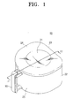
- FIG. 1 is a perspective view illustrating a dust collecting apparatus for a vacuum cleaner according to a first exemplary embodiment of the present invention
- FIG. 2 is a perspective view illustrating the dust collecting apparatus of FIG. 1 , in which an upper cover is separated;
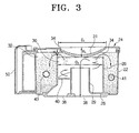
- FIG. 3 is a sectional view taken along a line III-III of FIG. 1 ;
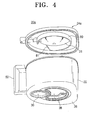
- FIGS. 4 is a perspective view illustrating a dust collecting apparatus for a vacuum cleaner according to a second exemplary embodiment of the present invention.
- FIG. 5 is a sectional view similar to FIG. 3 , in which the dust collecting apparatus of FIG. 4 is illustrated.
- FIGS.1 to 3 relate to a first exemplary embodiment of the present invention
- FIG. 1 is a perspective view
- FIG. 2 is an exploded perspective view in which an upper cover is separated
- FIG. 3 is a sectional view taken along a line III-III of FIG. 1 .
- a dust collecting apparatus 20 includes an inner wall 28, an outer wall 22, an upper cover 24, a lower wall 26 and a handle unit 50.
- the inner wall 28 is has a cylindrical shape and is injection molded integrally with the outer wall 22 and the lower wall 26.
- An inside space of the cylindrical inner wall 28 forms a cyclone chamber 30 and provided with an outlet pipe 29 projected from the lower wall 26 at a center portion thereof and a guide member 40 disposed between the inner wall 22 and the outlet pipe 29.
- the outlet pipe 29 is disposed vertically with a cylindrical shape and has an upper end which is lower than an upper end of the inner wall 28.
- the outlet pipe 29 functions as a whirling axis so that air can keep whirling force when the air is introduced from a lower portion, and separates the whirling air and the discharged air so that the discharged air is not mixed with the whirling air when the air is discharged to the lower portion.
- the outlet pipe 29 is communicated with a second opening 38 of the lower wall 38.
- the guide member 40 winds around the outlet pipe 29 in a helical plate to form a helical airflow path. As air introduced into the cyclone chamber 30 ascends around the outlet pipe 29 along the helical guide member 40, the whirling force of the air is increased.
- the outer wall 22 forms externals of the dust collecting apparatus 20 and is spaced by a predetermined distance from and parallel to the inner wall 28.
- the outer wall 22 has, as shown in FIG. 1 , a surface which is approximately straight linear and the other surface which is similar to semicircle.
- a height of the outer wall 22 is higher than a height of the inner wall 28 and the upper end of the outer wall 22 is sealed by the upper cover 24.
- a space between the inner wall 28 and the outer wall 22 is the dust collecting chamber 32. Referring to FIG. 3 , dust is discharged by centrifugal force through a dust discharging space 34 between the upper end of the inner wall 28 and the upper cover 24 to the dust collecting chamber 32.
- the upper cover 24 is constructed by a separate member so as to be attached to or removed from the upper end of the outer wall 22 and formed with a bulge portion 31 projected toward the cyclone chamber 30 at a center portion thereof.
- the bulge portion 31 has a spherical shape, in which a projected height is highest at a center portion of the bulge portion 31 and gradually lowered as it goes to the periphery. Referring to FIG. 3 , a diameter D1 of the bulge portion 31 is similar to or slightly greater than a diameter D2 of the inner wall 28.
- the diameter D1 of the bulge portion 31 is similar to the diameter D2 of the inner wall 28.
- a height H1 of the center portion 35 of the bulge portion 31 is almost equal to the distance H2 between upper end of the inner wall 28 and the upper cover 24.
- the bulge portion 31 projected in a spherical shape to the upper center of the cyclone chamber 30 prevents air or dust whirling in a circular manner in the upper portion of the cyclone chamber 30 form being concentrated to the center of the cyclone chamber 30, makes the air or dust to whirl in a larger circular manner and to make the dust to go over to the both sides of the cyclone chamber 30 (i.e. to dust discharging space 34).
- the bulge portion 31 increases a whirling diameter of the air and dust in the upper portion of the cyclone chamber 30 and prevents the dust from being flowed back to the upper portion of the outlet pipe 29 which is provided in the center portion of the cyclone chamber 30.
- even large dirt such as a bottle cap or a coin can easily go over to the dust collecting chamber 32 along the periphery of the rounded bulge portion 31.
- the lower wall 26 is injection molded integrally with the outer wall 26 and seals lower ends of the cyclone chamber 30 and the dust collecting chamber 32.
- the lower wall 26 is formed a first opening 36 for introducing air into the cyclone chamber 30 and the second opening 38 communicated with the outlet pipe 29 and discharging the air from the cyclone chamber 30 to the outside.
- the first opening 36 is communicated with a nozzle assembly (not shown) through a flexible hose (not shown) and an extension pipe (not shown) and the second opening 38 is communicated with a vacuum motor chamber (not shown) which is built in the cleaner body (not shown).
- the handle unit is, as shown FIGS. 1 to 3 , attached at a side of the outer wall 22 in a laid 'U' shape, and provided integrally at a side of the outer wall 22 in the present exemplary embodiment.
- FIGS. 4 and 5 are views illustrating a dust collecting apparatus according to a second exemplary embodiment of the present invention.
- FIG 4 is a perspective view and
- FIG. 5 is a sectional view.
- the dust collecting apparatus 20a according to the second exemplary embodiment has a structure identical to that of the dust collecting apparatus 20 according to the first exemplary embodiment, but further includes a skirt member 80 provided on a bottom surface of the upper cover 24a and having a cut portion 81 which is cut at a side thereof.
- An effect of restricting backflow of dust is increased as the skirt member 80 reduces the dust discharging space 34a which is the space between the upper end of the inner wall 28 and the upper cover 24a, and at the same time a large dirt can go over to the dust collecting chamber 32 through the cut portion 81 as a portion 81 is cut.
- a diameter D3 of the skirt member 80 is approximately equal to the diameter D1 of the bulge portion 31.
- outside air and dust are introduced through the first opening 36 of the lower wall 26 and the introduced air is whirled and ascended along the guide member 40.
- ascended dust laden air dust subjected to large centrifugal force whirls in a larger circular manner than the air, and the air and the dust are to whirl with the larger circle and to go to the outside of the circle by the bulge portion 31 in the upper portion of the cyclone chamber.
- the heavy dust is subjected to a large centrifugal force and thus goes over to the dust collecting chamber through the dust discharging space 34 which is the space between the upper end of the inner wall 28 and the upper cover 24a and the light air varies its flow direction again toward the outlet pipe 29 by suction force from the outlet pipe 29 and is discharged to through the outlet pipe 29 and the second opening 38 to the outside.
- the skirt member which narrows the dust discharging space 34 is not provided, even large dirt such as a bottle cap or a coin can be easily discharged to the dust collecting chamber 32.
- the dirt is hardly flowed back because the bulge portion 31 blocks the center portion of the cyclone chamber 30. Collected dust can be dumped from the dust collecting apparatus 20 by separating the upper cover 24 from the upper end of the outer wall 22.
- the dust collecting apparatus 20a has a better effect of preventing backflow of dust because it is provided with the skirt member 80 having the cut portion 81.
- a large sized member such as a bottle cap or a coin is discharged through the cut portion 81 to the dust collecting chamber 32.
- the dust collecting apparatus of the exemplary embodiments described above has advantages that it is not provided with a anti-backflow member and therefore movement of dust to the dust collecting chamber which surrounds the cyclone chamber is easily and quickly achieved, and particularly even large sized dirt such as a bottle cap or a coin can move from the cyclone chamber to the dust collecting chamber and at the same time backflow of the dust is prevented and whirling force of the dust at the upper portion of the cyclone chamber is increased as the bulge portion is provided at the center portion of the upper cover.
- the dust collecting apparatus of the exemplary embodiments has another advantage that it further provided with the bulge portion and the skirt member of which a portion is cut and therefore movement of large sized dirt can be easily achieved through the cut portion even though the backflow of the dust is more strictly restricted.
Landscapes
- Engineering & Computer Science (AREA)
- Mechanical Engineering (AREA)
- Filters For Electric Vacuum Cleaners (AREA)
- Cyclones (AREA)
Abstract
A dust collecting apparatus for a vacuum cleaner is provided. The apparatus includes an inner wall defining a cyclone chamber for whirling air in an inside thereof; an outer wall surrounding the outer periphery of the inner wall and spaced from the inner wall so as to form a dust collecting chamber for storing the dust between the inner wall and the outer wall; a handle unit attached to a side of the outer wall; an upper cover attached to an upper end of the outer wall so as to be spaced from an upper portion of the inner wall and provided with a bulge portion of which a center portion is projected toward the cyclone chamber; an outlet pipe provided in a center portion of the cyclone chamber, and a lower wall attached to lower ends of the inner wall and the outer wall. Therefore, a backflow of the dust is prevented by the bulge portion and at the same time large sized dirt can easily go over to the dust collecting chamber. Therefore, a backflow of the dust is prevented by the bulge portion and at the same time large sized dirt can easily go over to the dust collecting chamber.
Description
- The present disclosure relates to a dust collecting apparatus, and more particularly, to a dust collecting apparatus for a vacuum cleaner, which suck dust and separate the dust using a vacuum motor.
- A dust collecting apparatus used in a vacuum cleaner is an apparatus for sucking dust laden air and then separating the dust and discharging cleaned air. The dust collecting apparatus is divided into a filter type dust collecting apparatus for filtering dust using a filter alone and so-called a cyclone type dust collecting apparatus for whirling dust laden air to separate dust from the air using centrifugal force of the dust.
- A cyclone type dust collecting apparatus mainly has a cyclone body for whirling introduced air and a dust collecting receptacle for storing separated dust; a conventional cyclone dust collecting apparatus is constructed such that a cyclone body is disposed at an upper portion and a dust collecting receptacle is disposed at the lower portion so that dust separated from air falls free by gravity into the dust collecting receptacle. The dust collecting apparatus therefore has a large overall height and used in mainly an upright type vacuum cleaner more than a canister type vacuum cleaner.
- The present applicant has developed a dust collecting apparatus having a reduced overall height, as disclosed in
Korean Patent Number 560967 - Additional aspects the present invention will be set forth in part in the description which follows and, in part, will be obvious from the description, or may be learned by practice of the present invention.
- An aspect of the present invention is to provide a dust collecting apparatus for a vacuum cleaner having a dust collecting chamber surrounding a cyclone chamber and discharging dust through an upper portion of the cyclone chamber, in which large dirt such as a coin or a bottle cap can easily move from the cyclone chamber to the dust collecting chamber.
- The above aspect and/or other feature of the present invention can substantially be achieved by providing a dust collecting apparatus for a vacuum cleaner including an inner wall defining a cyclone chamber which whirls air in an inside thereof; an outer wall surrounding the outer periphery of the inner wall and spaced from the inner wall so as to form a dust collecting chamber which stories the dust between the inner wall and the outer wall; a handle unit attached to a side of the outer wall; an upper cover attached to an upper end of the outer wall so as to be spaced from an upper portion of the inner wall and provided with a bulge portion of which a center portion is projected toward the cyclone chamber; an outlet pipe provided in a center portion of the cyclone chamber; and a lower wall attached to lower ends of the inner wall and the outer wall. Therefore, a backflow of the dust is prevented by the bulge portion and at the same time large sized dirt can easily go over to the dust collecting chamber.
- The dust collecting apparatus may further include a skirt member projected from a bottom surface of the upper cover and provided with a cut portion. The skirt member may be an annular shape having a diameter greater than a diameter of the cylindrical inner wall.
- The upper cover may be mountable to or removable from the upper end of the outer wall, and the bulge portion may have a spherical shape in which a projected height is highest at a center portion of the
bulge portion 31 and gradually lowered as it goes to the periphery, and the center portion of the bulge portion may be projected to a height of the upper end of the inner wall. - The lower wall is provided with a first opening which introduces air and a second opening which discharges air, wherein during the air introduced through the first opening ascends and whirls, dust or dirt laden in the air is discharged to the dust collecting chamber and then cleaned air is discharged through the second opening.
- Therefore, the disclosed dust collecting apparatus has advantages that movement of dust to the dust collecting chamber which surrounds the cyclone chamber is easily and quickly achieved, and particularly even large sized dirt such as a bottle cap or a coin can move from the cyclone chamber to the dust collecting chamber and at the same time backflow of the dust is prevented and whirling force of the dust at the upper portion of the cyclone chamber is increased as the bulge portion is provided at the center portion of the upper cover.
- The dust collecting apparatus has another advantage that it further provided with the bulge portion and the skirt member of which a portion is cut and therefore movement of large sized dirt can be easily achieved through the cut portion even though the backflow of the dust is more strictly restricted.
- Above and other aspects of the present invention will become apparent and more readily appreciated from the following description of the exemplary embodiments, taken in conjunction with the accompany drawings of which:
-
FIG. 1 is a perspective view illustrating a dust collecting apparatus for a vacuum cleaner according to a first exemplary embodiment of the present invention; -
FIG. 2 is a perspective view illustrating the dust collecting apparatus ofFIG. 1 , in which an upper cover is separated; -
FIG. 3 is a sectional view taken along a line III-III ofFIG. 1 ; -
FIGS. 4 is a perspective view illustrating a dust collecting apparatus for a vacuum cleaner according to a second exemplary embodiment of the present invention; and -
FIG. 5 is a sectional view similar toFIG. 3 , in which the dust collecting apparatus ofFIG. 4 is illustrated. - Hereinafter, certain exemplary embodiments of the present invention will be described in detail with reference to the accompanying drawings.
-
FIGS.1 to 3 relate to a first exemplary embodiment of the present invention;FIG. 1 is a perspective view,FIG. 2 is an exploded perspective view in which an upper cover is separated andFIG. 3 is a sectional view taken along a line III-III ofFIG. 1 . - Referring to
FIGS. 1 to 3 , adust collecting apparatus 20 according to the first exemplary embodiment of the present invention includes aninner wall 28, anouter wall 22, anupper cover 24, alower wall 26 and ahandle unit 50. - The
inner wall 28 is has a cylindrical shape and is injection molded integrally with theouter wall 22 and thelower wall 26. An inside space of the cylindricalinner wall 28 forms acyclone chamber 30 and provided with anoutlet pipe 29 projected from thelower wall 26 at a center portion thereof and aguide member 40 disposed between theinner wall 22 and theoutlet pipe 29. Theoutlet pipe 29 is disposed vertically with a cylindrical shape and has an upper end which is lower than an upper end of theinner wall 28. Theoutlet pipe 29 functions as a whirling axis so that air can keep whirling force when the air is introduced from a lower portion, and separates the whirling air and the discharged air so that the discharged air is not mixed with the whirling air when the air is discharged to the lower portion. Theoutlet pipe 29 is communicated with asecond opening 38 of thelower wall 38. Theguide member 40 winds around theoutlet pipe 29 in a helical plate to form a helical airflow path. As air introduced into thecyclone chamber 30 ascends around theoutlet pipe 29 along thehelical guide member 40, the whirling force of the air is increased. - The
outer wall 22 forms externals of thedust collecting apparatus 20 and is spaced by a predetermined distance from and parallel to theinner wall 28. Theouter wall 22 has, as shown inFIG. 1 , a surface which is approximately straight linear and the other surface which is similar to semicircle. A height of theouter wall 22 is higher than a height of theinner wall 28 and the upper end of theouter wall 22 is sealed by theupper cover 24. A space between theinner wall 28 and theouter wall 22 is thedust collecting chamber 32. Referring toFIG. 3 , dust is discharged by centrifugal force through adust discharging space 34 between the upper end of theinner wall 28 and theupper cover 24 to thedust collecting chamber 32. - The
upper cover 24 is constructed by a separate member so as to be attached to or removed from the upper end of theouter wall 22 and formed with abulge portion 31 projected toward thecyclone chamber 30 at a center portion thereof. Thebulge portion 31 has a spherical shape, in which a projected height is highest at a center portion of thebulge portion 31 and gradually lowered as it goes to the periphery. Referring toFIG. 3 , a diameter D1 of thebulge portion 31 is similar to or slightly greater than a diameter D2 of theinner wall 28. This is because it is difficult to secure thedust discharging space 34 which is a space H2 between theinner wall 28 and theupper cover 24 if the diameter D1 of thebulge portion 31 is largely greater than the diameter D2 of theinner wall 28. Referring toFIG. 3 , the diameter D1 of thebulge portion 31 is similar to the diameter D2 of theinner wall 28. In addition, a height H1 of thecenter portion 35 of thebulge portion 31 is almost equal to the distance H2 between upper end of theinner wall 28 and theupper cover 24. By thisbulge portion 31, it is facilitated that dust goes over the upper end of thecyclone chamber 30 to be discharged to thedust collecting chamber 32 while it is prevented that dust goes over from thedust collecting chamber 32 to thecyclone chamber 30. Thebulge portion 31 projected in a spherical shape to the upper center of thecyclone chamber 30 prevents air or dust whirling in a circular manner in the upper portion of thecyclone chamber 30 form being concentrated to the center of thecyclone chamber 30, makes the air or dust to whirl in a larger circular manner and to make the dust to go over to the both sides of the cyclone chamber 30 (i.e. to dust discharging space 34). In other words, thebulge portion 31 increases a whirling diameter of the air and dust in the upper portion of thecyclone chamber 30 and prevents the dust from being flowed back to the upper portion of theoutlet pipe 29 which is provided in the center portion of thecyclone chamber 30. In addition, as shown inFIG. 3 , even large dirt such as a bottle cap or a coin can easily go over to thedust collecting chamber 32 along the periphery of therounded bulge portion 31. - The
lower wall 26 is injection molded integrally with theouter wall 26 and seals lower ends of thecyclone chamber 30 and thedust collecting chamber 32. Thelower wall 26 is formed afirst opening 36 for introducing air into thecyclone chamber 30 and the second opening 38 communicated with theoutlet pipe 29 and discharging the air from thecyclone chamber 30 to the outside. Thefirst opening 36 is communicated with a nozzle assembly (not shown) through a flexible hose (not shown) and an extension pipe (not shown) and thesecond opening 38 is communicated with a vacuum motor chamber (not shown) which is built in the cleaner body (not shown). - The handle unit is, as shown
FIGS. 1 to 3 , attached at a side of theouter wall 22 in a laid 'U' shape, and provided integrally at a side of theouter wall 22 in the present exemplary embodiment. -
FIGS. 4 and5 are views illustrating a dust collecting apparatus according to a second exemplary embodiment of the present invention;FIG 4 is a perspective view andFIG. 5 is a sectional view. - The dust collecting
apparatus 20a according to the second exemplary embodiment has a structure identical to that of thedust collecting apparatus 20 according to the first exemplary embodiment, but further includes askirt member 80 provided on a bottom surface of theupper cover 24a and having acut portion 81 which is cut at a side thereof. An effect of restricting backflow of dust is increased as theskirt member 80 reduces thedust discharging space 34a which is the space between the upper end of theinner wall 28 and theupper cover 24a, and at the same time a large dirt can go over to thedust collecting chamber 32 through thecut portion 81 as aportion 81 is cut. A diameter D3 of theskirt member 80 is approximately equal to the diameter D1 of thebulge portion 31. - An operation of the aforementioned
dust collecting apparatus 20 of the first exemplary embodiment will be described hereinafter in detail with reference toFIG. 3 . - Referring to
FIG. 3 , outside air and dust are introduced through thefirst opening 36 of thelower wall 26 and the introduced air is whirled and ascended along theguide member 40. In ascended dust laden air, dust subjected to large centrifugal force whirls in a larger circular manner than the air, and the air and the dust are to whirl with the larger circle and to go to the outside of the circle by thebulge portion 31 in the upper portion of the cyclone chamber. The heavy dust is subjected to a large centrifugal force and thus goes over to the dust collecting chamber through thedust discharging space 34 which is the space between the upper end of theinner wall 28 and theupper cover 24a and the light air varies its flow direction again toward theoutlet pipe 29 by suction force from theoutlet pipe 29 and is discharged to through theoutlet pipe 29 and thesecond opening 38 to the outside. At this time, because the skirt member which narrows thedust discharging space 34 is not provided, even large dirt such as a bottle cap or a coin can be easily discharged to thedust collecting chamber 32. However, the dirt is hardly flowed back because thebulge portion 31 blocks the center portion of thecyclone chamber 30. Collected dust can be dumped from thedust collecting apparatus 20 by separating theupper cover 24 from the upper end of theouter wall 22. - The
dust collecting apparatus 20a according to the second exemplary embodiment has a better effect of preventing backflow of dust because it is provided with theskirt member 80 having the cutportion 81. In addition, a large sized member such as a bottle cap or a coin is discharged through thecut portion 81 to thedust collecting chamber 32. - The dust collecting apparatus of the exemplary embodiments described above has advantages that it is not provided with a anti-backflow member and therefore movement of dust to the dust collecting chamber which surrounds the cyclone chamber is easily and quickly achieved, and particularly even large sized dirt such as a bottle cap or a coin can move from the cyclone chamber to the dust collecting chamber and at the same time backflow of the dust is prevented and whirling force of the dust at the upper portion of the cyclone chamber is increased as the bulge portion is provided at the center portion of the upper cover.
- In addition, the dust collecting apparatus of the exemplary embodiments has another advantage that it further provided with the bulge portion and the skirt member of which a portion is cut and therefore movement of large sized dirt can be easily achieved through the cut portion even though the backflow of the dust is more strictly restricted.
Claims (7)
- A dust collecting apparatus for a vacuum cleaner, comprising:an inner wall defining a cyclone chamber which whirls air in an inside thereof;an outer wall surrounding the outer periphery of the inner wall and spaced from the inner wall so as to form a dust collecting chamber which stores the dust between the inner wall and the outer wall;a handle unit attached to a side of the outer wall;an upper cover attached to an upper end of the outer wall so as to be spaced from an upper portion of the inner wall and provided with a bulge portion of which a center portion is projected toward the cyclone chamber;an outlet pipe provided in a center portion of the cyclone chamber, anda lower wall attached to lower ends of the inner wall and the outer wall.
- The dust collecting apparatus for a vacuum cleaner of claim 1, further comprising a skirt member projected from a bottom surface of the upper cover and provided with a cut portion.
- The dust collecting apparatus for a vacuum cleaner of claim 2, wherein the skirt member is an annular shape having a diameter greater than a diameter of the cylindrical inner wall.
- The dust collecting apparatus for a vacuum cleaner of any of claims 1 to 3, wherein the upper cover is mountable to or removable from the upper end of the outer wall.
- The dust collecting apparatus for a vacuum cleaner of any of claims 1 to 4, wherein the bulge portion has a spherical shape in which a projected height is highest at a center portion of the bulge portion 31 and gradually lowered as it goes to the periphery.
- The dust collecting apparatus for a vacuum cleaner of claim 5, wherein the center portion of the bulge portion is projected to a height of the upper end of the inner wall.
- The dust collecting apparatus for a vacuum cleaner of any one of claim 1 to claim 6, wherein the lower wall is provided with a first opening for introducing air and a second opening for discharging air, wherein during the air introduced through the first opening ascends and whirls, dust or dirt laden in the air is discharged to the dust collecting chamber and then cleaned air is discharged through the second opening.
Applications Claiming Priority (1)
| Application Number | Priority Date | Filing Date | Title |
|---|---|---|---|
| KR20060136892 | 2006-12-28 |
Publications (1)
| Publication Number | Publication Date |
|---|---|
| EP1938734A2 true EP1938734A2 (en) | 2008-07-02 |
Family
ID=39295995
Family Applications (1)
| Application Number | Title | Priority Date | Filing Date |
|---|---|---|---|
| EP20070290968 Withdrawn EP1938734A2 (en) | 2006-12-28 | 2007-08-01 | Dust collecting apparatus for vacuum cleaner |
Country Status (3)
| Country | Link |
|---|---|
| EP (1) | EP1938734A2 (en) |
| CN (1) | CN101209194A (en) |
| RU (1) | RU2007126419A (en) |
Cited By (4)
| Publication number | Priority date | Publication date | Assignee | Title |
|---|---|---|---|---|
| JP2014068719A (en) * | 2012-09-28 | 2014-04-21 | Mitsubishi Electric Corp | Centrifugal separator |
| EP2842470A1 (en) | 2013-08-28 | 2015-03-04 | BSH Bosch und Siemens Hausgeräte GmbH | Eddy tube separator with ejection opening for coarse dirt |
| CN106308682A (en) * | 2016-10-31 | 2017-01-11 | 上海未来伙伴机器人有限公司 | Cyclone dust collector |
| CN109953692A (en) * | 2017-12-23 | 2019-07-02 | 天佑电器(苏州)有限公司 | Cyclone separator and dust catcher |
Families Citing this family (3)
| Publication number | Priority date | Publication date | Assignee | Title |
|---|---|---|---|---|
| FR2967043B1 (en) * | 2010-11-04 | 2013-08-23 | Seb Sa | VACUUM CLEANER WITHOUT CYCLONE SEPARATION BAG |
| CN103284658A (en) * | 2012-02-28 | 2013-09-11 | 乐金电子(天津)电器有限公司 | Central type cyclone separation structure in dust collection cylinder |
| CN113305003B (en) * | 2021-06-02 | 2024-01-30 | 安徽捷迅光电技术有限公司 | Brown rice dust removal case |
-
2007
- 2007-07-12 RU RU2007126419/12A patent/RU2007126419A/en not_active Application Discontinuation
- 2007-07-13 CN CNA2007101291771A patent/CN101209194A/en active Pending
- 2007-08-01 EP EP20070290968 patent/EP1938734A2/en not_active Withdrawn
Cited By (5)
| Publication number | Priority date | Publication date | Assignee | Title |
|---|---|---|---|---|
| JP2014068719A (en) * | 2012-09-28 | 2014-04-21 | Mitsubishi Electric Corp | Centrifugal separator |
| EP2842470A1 (en) | 2013-08-28 | 2015-03-04 | BSH Bosch und Siemens Hausgeräte GmbH | Eddy tube separator with ejection opening for coarse dirt |
| DE102013217211A1 (en) | 2013-08-28 | 2015-03-05 | BSH Bosch und Siemens Hausgeräte GmbH | Swirl tube separator with coarse dirt discharge opening |
| CN106308682A (en) * | 2016-10-31 | 2017-01-11 | 上海未来伙伴机器人有限公司 | Cyclone dust collector |
| CN109953692A (en) * | 2017-12-23 | 2019-07-02 | 天佑电器(苏州)有限公司 | Cyclone separator and dust catcher |
Also Published As
| Publication number | Publication date |
|---|---|
| RU2007126419A (en) | 2009-01-20 |
| CN101209194A (en) | 2008-07-02 |
Similar Documents
| Publication | Publication Date | Title |
|---|---|---|
| US7559964B2 (en) | Dust separating apparatus | |
| TWI803100B (en) | Cleaner | |
| US7547351B2 (en) | Multi cyclone dust collector for a vacuum cleaner | |
| AU2007201420B2 (en) | Dust collector of vacuum cleaner | |
| KR100560967B1 (en) | Cyclone dust collector | |
| CN207412114U (en) | Vacuum cleaner | |
| EP1676516A1 (en) | Dust collection assembly and vacuum cleaner with the same | |
| CN101449948B (en) | Cyclone system for dust collector and dust collector with the same | |
| CN1947641A (en) | Multi-cyclone dust collector for vacuum cleaner and dust collecting method | |
| US7662202B2 (en) | Dust collector of vacuum cleaner | |
| KR20100084127A (en) | Cyclonic separation device with acceleration ramp | |
| CN1654002A (en) | Cyclone dust collecting apparatus for a vacuum cleaner | |
| US10028630B2 (en) | Cleaner | |
| AU2008207600A1 (en) | Multi-cyclone dust separator | |
| CN101209194A (en) | Dust collection equipment for vacuum cleaners | |
| EP1676638B1 (en) | Apparatus for collecting dust and vacuum cleaner having the same | |
| EP1774890B1 (en) | A multi cyclone dust collector for a vacuum cleaner | |
| KR100672483B1 (en) | Dust collector of vacuum cleaner | |
| KR100546622B1 (en) | Dust collector of vacuum cleaner | |
| EP1743558B1 (en) | Dust separating apparatus | |
| KR100546625B1 (en) | Dust collector of vacuum cleaner | |
| KR101306695B1 (en) | Dust Collecting Device | |
| KR20080066291A (en) | Dust collection unit of the vacuum cleaner | |
| KR100546628B1 (en) | Dust collector of vacuum cleaner | |
| KR100556444B1 (en) | Dust collector of vacuum cleaner |
Legal Events
| Date | Code | Title | Description |
|---|---|---|---|
| PUAI | Public reference made under article 153(3) epc to a published international application that has entered the european phase |
Free format text: ORIGINAL CODE: 0009012 |
|
| AK | Designated contracting states |
Kind code of ref document: A2 Designated state(s): AT BE BG CH CY CZ DE DK EE ES FI FR GB GR HU IE IS IT LI LT LU LV MC MT NL PL PT RO SE SI SK TR |
|
| AX | Request for extension of the european patent |
Extension state: AL BA HR MK RS |
|
| STAA | Information on the status of an ep patent application or granted ep patent |
Free format text: STATUS: THE APPLICATION IS DEEMED TO BE WITHDRAWN |
|
| 18D | Application deemed to be withdrawn |
Effective date: 20090901 |