EP1937941B1 - Inter-turbine temperature display compensation method - Google Patents
Inter-turbine temperature display compensation method Download PDFInfo
- Publication number
- EP1937941B1 EP1937941B1 EP06799964A EP06799964A EP1937941B1 EP 1937941 B1 EP1937941 B1 EP 1937941B1 EP 06799964 A EP06799964 A EP 06799964A EP 06799964 A EP06799964 A EP 06799964A EP 1937941 B1 EP1937941 B1 EP 1937941B1
- Authority
- EP
- European Patent Office
- Prior art keywords
- value
- temperature
- logic
- inter turbine
- inter
- Prior art date
- Legal status (The legal status is an assumption and is not a legal conclusion. Google has not performed a legal analysis and makes no representation as to the accuracy of the status listed.)
- Not-in-force
Links
- 238000000034 method Methods 0.000 title claims description 20
- 230000003068 static effect Effects 0.000 claims description 11
- 230000008859 change Effects 0.000 claims description 4
- 230000006870 function Effects 0.000 description 6
- 230000004044 response Effects 0.000 description 6
- 238000002485 combustion reaction Methods 0.000 description 4
- 239000000446 fuel Substances 0.000 description 4
- 238000009434 installation Methods 0.000 description 4
- 230000008901 benefit Effects 0.000 description 3
- 238000010586 diagram Methods 0.000 description 3
- 229920000747 poly(lactic acid) Polymers 0.000 description 2
- 239000000463 material Substances 0.000 description 1
- 239000000203 mixture Substances 0.000 description 1
- 238000012986 modification Methods 0.000 description 1
- 230000004048 modification Effects 0.000 description 1
- 238000012544 monitoring process Methods 0.000 description 1
- 230000000007 visual effect Effects 0.000 description 1
Images



Classifications
-
- F—MECHANICAL ENGINEERING; LIGHTING; HEATING; WEAPONS; BLASTING
- F01—MACHINES OR ENGINES IN GENERAL; ENGINE PLANTS IN GENERAL; STEAM ENGINES
- F01D—NON-POSITIVE DISPLACEMENT MACHINES OR ENGINES, e.g. STEAM TURBINES
- F01D21/00—Shutting-down of machines or engines, e.g. in emergency; Regulating, controlling, or safety means not otherwise provided for
- F01D21/12—Shutting-down of machines or engines, e.g. in emergency; Regulating, controlling, or safety means not otherwise provided for responsive to temperature
-
- F—MECHANICAL ENGINEERING; LIGHTING; HEATING; WEAPONS; BLASTING
- F01—MACHINES OR ENGINES IN GENERAL; ENGINE PLANTS IN GENERAL; STEAM ENGINES
- F01D—NON-POSITIVE DISPLACEMENT MACHINES OR ENGINES, e.g. STEAM TURBINES
- F01D17/00—Regulating or controlling by varying flow
- F01D17/02—Arrangement of sensing elements
- F01D17/08—Arrangement of sensing elements responsive to condition of working-fluid, e.g. pressure
- F01D17/085—Arrangement of sensing elements responsive to condition of working-fluid, e.g. pressure to temperature
-
- F—MECHANICAL ENGINEERING; LIGHTING; HEATING; WEAPONS; BLASTING
- F01—MACHINES OR ENGINES IN GENERAL; ENGINE PLANTS IN GENERAL; STEAM ENGINES
- F01D—NON-POSITIVE DISPLACEMENT MACHINES OR ENGINES, e.g. STEAM TURBINES
- F01D21/00—Shutting-down of machines or engines, e.g. in emergency; Regulating, controlling, or safety means not otherwise provided for
- F01D21/003—Arrangements for testing or measuring
-
- F—MECHANICAL ENGINEERING; LIGHTING; HEATING; WEAPONS; BLASTING
- F02—COMBUSTION ENGINES; HOT-GAS OR COMBUSTION-PRODUCT ENGINE PLANTS
- F02C—GAS-TURBINE PLANTS; AIR INTAKES FOR JET-PROPULSION PLANTS; CONTROLLING FUEL SUPPLY IN AIR-BREATHING JET-PROPULSION PLANTS
- F02C6/00—Plural gas-turbine plants; Combinations of gas-turbine plants with other apparatus; Adaptations of gas-turbine plants for special use
-
- F—MECHANICAL ENGINEERING; LIGHTING; HEATING; WEAPONS; BLASTING
- F02—COMBUSTION ENGINES; HOT-GAS OR COMBUSTION-PRODUCT ENGINE PLANTS
- F02C—GAS-TURBINE PLANTS; AIR INTAKES FOR JET-PROPULSION PLANTS; CONTROLLING FUEL SUPPLY IN AIR-BREATHING JET-PROPULSION PLANTS
- F02C9/00—Controlling gas-turbine plants; Controlling fuel supply in air- breathing jet-propulsion plants
- F02C9/26—Control of fuel supply
- F02C9/28—Regulating systems responsive to plant or ambient parameters, e.g. temperature, pressure, rotor speed
-
- F—MECHANICAL ENGINEERING; LIGHTING; HEATING; WEAPONS; BLASTING
- F05—INDEXING SCHEMES RELATING TO ENGINES OR PUMPS IN VARIOUS SUBCLASSES OF CLASSES F01-F04
- F05D—INDEXING SCHEME FOR ASPECTS RELATING TO NON-POSITIVE-DISPLACEMENT MACHINES OR ENGINES, GAS-TURBINES OR JET-PROPULSION PLANTS
- F05D2270/00—Control
- F05D2270/30—Control parameters, e.g. input parameters
- F05D2270/303—Temperature
Definitions
- the present invention relates to a method of compensating for mismatches between inter turbine temperatures of two or more gas turbine engines.
- Gas turbine engines such as multi-spool gas turbine engines, may be used to provide propulsion power for aircraft.
- an aircraft includes two redundant gas turbine engines.
- the gas turbine engines may be automatically controlled via an engine controller such as, for example, a DEEC (Digital Electronic Engine Controller).
- the engine controller receives signals from various sensors within the engine, as well as from various pilot-manipulated controls. In response to these signals, the engine controller regulates the operation of the gas turbine engine.
- DEEC Digital Electronic Engine Controller
- various sensors In addition to providing signals for use in the engine controller, various sensors also supply signals that are used to display the sensed parameter.
- the low pressure turbine speed or fan speed (N1), the high pressure turbine speed (N2), the fuel flow, the oil pressure, and the inter turbine temperature of each engine may be displayed. It is common to display like parameters for each engine together or adjacent to provide the flight crew with a visual means of comparing the operations of the two engines. For example, the inter turbine temperatures of each engine are typically displayed together or adjacent.
- the simultaneous display of like engine parameters provides various advantages, it can also exhibit certain drawbacks.
- the inter turbine temperatures may be slightly mismatched. Such mismatches may not be indicative of any type of anomaly. Indeed, on many aircraft such mismatches may occur during normal engine operations. Nonetheless, to the flight crew personnel the slight inter turbine temperature mismatches may be a nuisance and an unnecessary distraction.
- Document US 4787053 discloses a comprehensive turbine engine monitoring and recording system including an electronic unit which input information includes left and right engine's temperature with over temperature alarm signals for the left and right engine.
- the present invention provides a method of safely and unobtrusively compensating for mismatched inter turbine temperatures between two gas turbine engines.
- a method of compensating mismatched inter turbine temperature of two gas turbine engines includes the step of sensing the inter turbine temperature of each gas turbine engine and supplying sensed inter turbine temperature values representative thereof. A determination is made as to which gas turbine engine has a lower sensed inter turbine temperature value and which has a higher sensed inter turbine temperature value. A temperature compensation value is added to the lower sensed inter turbine temperature value to thereby increase the lower sensed inter turbine temperature value to a compensated inter turbine temperature value that is substantially equal to the higher sensed inter turbine temperature value.
- inter turbine temperature mismatch compensation control logic includes compensation value determination logic, and temperature compensation logic.
- the compensation value determination logic is adapted to receive a local engine inter turbine temperature value and a cross-engine inter turbine temperature value, and is operable, in response thereto, to compare the local engine and cross-engine inter turbine temperature values and to determine a temperature compensation value based at least in part on the comparison.
- the temperature compensation logic is coupled to receive the local engine inter turbine temperature value and the temperature compensation value and is operable, in response thereto, to add the temperature compensation value to the local inter turbine temperature value, to thereby supply a compensated inter turbine temperature value.
- FIG. 1 shows an exemplary multi-spool gas turbine main propulsion engine coupled to an engine controller and display control logic
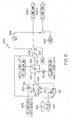
- FIGS. 2-4 are simplified functional block diagrams of an embodiment of inter turbine temperature display control logic according to an embodiment of the present invention.
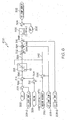
- FIGS. 5-7 are simplified functional block diagrams of an embodiment of inter turbine temperature display control logic according to an alternate embodiment of the present invention.
- FIG. 1 an embodiment of an exemplary multi-spool gas turbine main propulsion engine 100 is shown, and includes an intake section 102, a compressor section 104, a combustion section 106, a turbine section 108, and an exhaust section 112.
- the intake section 102 includes a fan 114, which is mounted in a fan case 116.
- the fan 114 draws air into the intake section 102 and accelerates it.
- a fraction of the accelerated air exhausted from the fan 114 is directed through a bypass section 118 disposed between the fan case 116 and an engine cowl 122, and generates propulsion thrust.
- the remaining fraction of air exhausted from the fan 114 is directed into the compressor section 104.
- the compressor section 104 may include one or more compressors 124, which raise the pressure of the air directed into it from the fan 114, and directs the compressed air into the combustion section 106. In the depicted embodiment, only a single compressor 124 is shown, though it will be appreciated that one or more additional compressors could be used.
- the combustion section 106 which includes a combustor assembly 126, the compressed air is mixed with fuel supplied from a fuel source (not shown). The fuel/air mixture is combusted, generating high energy combusted gas that is then directed into the turbine section 108.
- the turbine section 108 includes one or more turbines.
- the turbine section 108 includes two turbines, a high pressure turbine 128, and a low pressure turbine 132.
- the propulsion engine 100 could be configured with more or less than this number of turbines.
- the combusted gas from the combustion section 106 expands through each turbine 128, 132, causing it to rotate.
- the gas is then exhausted through a propulsion nozzle 134 disposed in the exhaust section 112, generating additional propulsion thrust.
- the turbines 128, 132 rotate, each drives equipment in the main propulsion engine 100 via concentrically disposed shafts or spools.
- the high pressure turbine 128 drives the compressor 124 via a high pressure spool 136
- the low pressure turbine 132 drives the fan 114 via a low pressure spool 138.
- the main propulsion engine 100 is controlled, at least partially, by an engine controller 150 such as, for example, a DEEC (Digital Electronic Engine Controller).
- the engine controller 150 controls the operation of the main propulsion engine 100. More specifically, the engine controller 150 receives signals from various sensors and from various pilot-manipulated controls and, in response to these signals, controls the overall operation of the propulsion engine 100. Included among these signals are an inter turbine temperature (ITT) signal, which is supplied from an inter turbine temperature sensor 142 disposed between the high pressure turbine 128 and the low pressure turbine 132, a power lever angle (PLA) signal, which is supplied from an engine power lever 144 located in the cockpit, and a fan speed (N1) signal, which is supplied from a fan speed sensor 146 in the engine 100.
- ITT inter turbine temperature
- PDA power lever angle
- N1 fan speed
- the inter turbine temperature signal in addition to being supplied to the engine controller 150, is also supplied to a display circuit 148.
- the display circuit 148 receives the inter turbine temperature signal supplied not only from the local engine 100, but also from a non-illustrated cross-engine.
- the display circuit 148 in response to the inter turbine temperature signals, causes an inter turbine temperature display 152 to simultaneously display the inter turbine temperatures of the local engine 154 and the cross-engine 156.
- the display circuit 148 implements, among other functions, control logic 160 that, except for a few exceptions that are described further below, artificially biases the inter turbine temperature display 152 so that, if the local and cross-engine inter turbine temperatures 154, 156 are slightly mismatched, the temperatures will be displayed substantially equally, without the mismatch.
- FIGS. 2-4 simplified functional block diagrams of an embodiment of the inter turbine temperature display control logic 160 is shown, and will now be described in more detail. Before doing so, however, it is noted that the display control logic 160 is depicted using various schematic symbols that represent physical components. It will be appreciated that this is done for clarity and ease of description, and that the display control logic 160 could be implemented using one or more of these discrete physical components or it could be implemented fully in software or it could be implemented using a combination of hardware and software.
- the display control logic 160 associated with each propulsion engine inter turbine temperature sensor 142 includes compensation value determination logic 200 ( FIG. 2 ), temperature compensation logic 300 ( FIG. 3 ), and event determination logic 400 ( FIG. 4 ).
- the compensation value determination logic 200 receives signals representative of a local engine inter turbine temperature value (ITT) 202 and a cross-engine inter turbine temperature value (ITT_XE) 204.
- the compensation value determination logic 200 compares the local engine and cross-engine inter turbine temperature values 202, 204 and, based at least in part on the comparison, determines a temperature compensation value (ITT_COMP_TEMP) 208. To do so, the compensation value determination logic 200 includes comparator logic 212, first addition logic 214, subtraction logic 216, limiter logic 218, second addition logic 222, and rate limiter logic 224.
- the comparator logic 212 receives and compares the local engine inter turbine temperature value 202 and the cross-engine inter turbine temperature value 204. If the local engine inter turbine temperature value 202 is less than the cross-engine inter turbine temperature value 204, then the comparator logic 212 supplies a logical "1" value, otherwise the comparator 212 supplies a logical "0" value.
- the first addition logic 214 receives the local engine inter turbine temperature value 202 and a static compensation value (ITT_COMP_STATIC) 206, and supplies a statically compensated inter turbine temperature value 226 that is representative of the mathematical summation of the two values to the subtraction logic 216.
- the subtraction logic 216 receives the statically compensated inter turbine temperature value 226 and the cross-engine inter turbine temperature value 204, and supplies a dynamically compensated inter turbine temperature value 228 that is representative of the mathematical difference of the two values.
- the dynamically compensated inter turbine temperature value 228 is supplied to the limiter logic 218. Conversely, if the output of the comparator 212 is a logical "1" value, a negated static compensation value 232 is supplied to the limiter logic 218.
- the negated static compensation value 232 is supplied from multiplier logic 233 that multiplies the static compensation value 206 by a negative one (-1).
- the static compensation value 206 is a predetermined value that is set based upon testing, such as installation testing in the aircraft.
- the static compensation value 206 is preferably stored in non-illustrated memory, such as non-volatile memory, and is available for retrieval therefrom by the compensation value determination logic 200.
- the static compensation value 206 has a default value of "0" but can be set to a predetermined range of positive temperature values. Although this range may vary depending, for example, on the particular engines 100 and aircraft installation, in the depicted embodiment the predetermined range is from 0 to 50°C.
- the limiter logic 218 receives the dynamically compensated inter turbine temperature value 228.
- the limiter logic 218 functions to limit the dynamically compensated inter turbine temperature value 228 to a value within a predetermined range of values. More specifically, the dynamically compensated inter turbine temperature value 228 is not limited unless it is more positive or more negative than the maximum positive or maximum negative values, respectively. If, however, the dynamically compensated inter turbine temperature value 228 is more positive or more negative than the maximum positive or maximum negative values, respectively, the limiter logic 218 will set the dynamically compensated inter turbine temperature value 228 equal to the maximum positive or maximum negative value, respectively.
- the predetermined maximum positive and maximum negative values are also set based upon testing and, as with the static compensation value 206, may vary, for example, with particular engines 100 and aircraft installations. In the depicted embodiment, however, the maximum positive and maximum negative values are selectable to values between -50 °C and +50 °C, and are set to default to values of -30 °C and +30°C. No matter the specific values that are used, the limiter logic 218 supplies a magnitude-limited dynamically compensated inter turbine temperature value 234 to the second addition logic 222.
- the second addition logic 222 receives the magnitude-limited dynamically compensated inter turbine temperature value 234 and the static compensation value 206, and supplies a non-rate-limited temperature compensation value 208' that is representative of the mathematical summation of the two values.
- the non-rate-limited temperature compensation value 208' is supplied to the rate limiter logic 224, depending upon whether the event determination logic 400 has determined that one or more predefined events are presently occurring. More specifically, if the event determination logic 400 not determines that no predefined events are presently occurring, then the non-rate-limited temperature compensation value 208' is supplied to the rate limiter logic 224.
- the event determination logic 400 determines that one or more predefined events are presently occurring, then the non-rate-limited temperature compensation value 208' is not supplied to the rate limiter logic 224.
- the event determination logic 400, the predefined events, and the functionality implemented by the event determination logic 400 are described in more detail further below.
- the rate limiter logic 224 receives either the non-rate-limited temperature compensation value 208', the previously determined temperature compensation value 208, or a zero value, and functions to limit the rate of change of the received value to predetermined positive and negative rate values.
- the particular value that the rate limiter logic 224 receives depends upon whether the event determination logic 400 has determined that one or more predefined events is presently occurring. If, as noted above, the event determination logic 400 determines that no predefined events are presently occurring, then the rate limiter logic 224 will limit the rate of change of the non-rate-limited temperature compensation value 208' and supply the temperature compensation value 208.
- the rate limiter logic 224 will receive either the previously determined temperature compensation value 208, via a feedback loop 236, or a zero value. As will be described in more detail further below, the particular one of these two values will depend on the particular predefined event that is presently occurring. Nonetheless, the rate limiter logic 224 will supply these constant values as the temperature compensation value 208. It will be appreciated that if the zero value is supplied to the rate limiter logic 224 the rate of change from the previously determined temperature compensation value 208 to zero will be limited.
- the predetermined rate values implemented by the rate limiter logic 224 are also set based upon testing and, as described above, may vary, for example, with particular engines 100 and aircraft installations.
- the predetermined rate values are selectable to any desired range, and are set to default to -1 °C/second and +1 °C/second. No matter the specific values that are used, the rate limiter logic 224 supplies the temperature compensation value 208 to the temperature compensation logic 300.
- the temperature compensation logic 300 receives the temperature compensation value 208 from the temperature compensation determination logic 200, and the signal representative of the local engine inter turbine temperature value 202.
- the temperature compensation logic 300 adds the temperature compensation value 208 to the local inter turbine temperature value 202, and supplies a signal representative of a compensated inter turbine temperature value (ITT_COMP_DISPLAY) 302 for display on the inter turbine temperature display 152.
- the temperature compensation logic 300 additionally reduces the temperature compensation value 208 if the compensated inter turbine temperature value 302 exceeds a predetermined threshold value 304.
- the temperature compensation logic 300 includes first, second, and third addition logic 303, 306, and 308, respectively, first, second, and third subtraction logic 312, 314, and 316, respectively, limiter logic 318, division logic 322, and multiplication logic 324.
- the first addition logic 303 receives the local engine inter turbine temperature value 202 and the temperature compensation value 208 and supplies a non-limited compensated temperature value 326 representative of the mathematical summation of the two values to the second subtraction logic 314.
- the first subtraction logic 312 receives a predetermined maximum inter turbine temperature value (REDLINE) 328 and a washout value (REDLINE_WASHOUT) 332, and supplies the predetermined threshold value 304, which is representative of the mathematical difference of the two values to the second subtraction logic 314.
- the predetermined maximum inter turbine temperature value 328 is, as the term connotes, the maximum allowable inter turbine temperature that the local engine 100 may attain and be kept operating. It will be appreciated that the specific maximum temperature value may vary depending, for example, on the particular engine 100 being used.
- the predetermined maximum inter turbine temperature value 328 is preferably stored in non-illustrated memory, such as non-volatile memory, and is available for retrieval therefrom by the temperature compensation logic 300.
- the washout value 332 is a temperature value that is used to set the predetermined threshold value 304.
- the predetermined threshold value 304 is a temperature value representative of a predetermined number of degrees below the predetermined maximum inter turbine temperature value 328 at which the temperature compensation logic 300 begins reducing the temperature compensation value 208.
- the washout value 332 is set during testing, may range over any one of numerous desired value ranges, and may default to any one of numerous values within the value range. In the depicted embodiment, however, the washout value 332 may be set within the range of 0 to 50°C, and defaults to 10°C.
- the washout value 332 is also preferably stored in non-illustrated memory, such as non-volatile memory, and is available for retrieval therefrom by the temperature compensation logic 300.
- the non-limited compensated temperature value 326 and the predetermined threshold value 304 are both supplied to the second subtraction logic 314.
- the second subtraction logic 314 supplies a difference value 336 representative of the mathematical difference of the two values to the limiter logic 318.
- the limiter logic 318 similar to the limiter logic 218 previously described, functions to limit the difference value 336 to a value within a predetermined range of values and supplies a magnitude-limited difference value 338. More specifically, the difference value 336 is not limited unless it is more positive than a maximum positive value 342 or is less than zero.
- the limiter logic 318 will set the magnitude-limited difference value 338 equal to the maximum positive value 342 or zero, respectively.
- the maximum positive value 342 is supplied from the second addition logic 306, and is the mathematical summation of the temperature compensation value 208 and the washout value 332.
- the magnitude-limited difference value 338 is supplied to the division logic 322, which also receives the maximum positive value 342.
- the division logic 322 uses the magnitude-limited difference value 338 as a quotient numerator and the maximum positive value 342 as a quotient denominator, and supplies a quotient value 344 that is representative of the mathematical quotient of the two values to the multiplication logic 324.
- the multiplication logic 324 receives the quotient value 344 and the temperature compensation value 208, and supplies a product value 346 representative of the mathematical product of the two values to the third subtraction logic 316.
- the third subtraction logic 316 receives the product value 346 and the temperature compensation value 208, and supplies a reduced temperature compensation value 348 representative of the mathematical difference of the two values.
- the reduced temperature compensation value 348 along with the local engine inter turbine temperature value 202, is supplied to the third addition logic 308.
- the reduced temperature compensation value 348 depending on the value of the non-limited compensated temperature value 326, will either be equal to the temperature compensation value 208 supplied from the temperature compensation determination logic 200, or some fraction thereof.
- the compensated temperature value 302 will either be equal to the non-limited compensated temperature value 326, or to a value less than the non-limited compensated temperature value 326. More specifically, if the non-limited compensated temperature value 326 is either equal to or less than the predetermined threshold value 304, then the temperature compensation value 208 will not be reduced and the compensated temperature value 302 will be equal to the non-limited compensated temperature value 326. Conversely, if the non-limited compensated temperature value 326 is greater than the predetermined threshold value 304, then the temperature compensation value 208 will be reduced and the compensated temperature value 302 will be less than the non-limited compensated temperature value 326.
- the above-described functionality of the temperature compensation logic 300 causes magnitude of the temperature compensation value 208 to begin being reduced linearly once the local engine inter turbine temperature value 202 reaches the predetermined threshold value 304. This functionality ultimately causes the temperature compensation value 208 to be reduced to zero when the local engine inter turbine temperature value 202 reaches the predetermined maximum inter turbine temperature value 328.
- the temperature compensation value 208 may be held constant at the previously determined value, or it may be set to a zero value.
- the event determination logic 400 functions to determine whether one or more of the predefined events is occurring. The event determination logic 400 is depicted in FIG. 4 , and with reference thereto, will now be described in more detail.
- the event determination logic 400 includes first, second, third, and fourth OR logic 402, 404, 406, and 408, respectively, first and second comparator logic 412 and 414, respectively, and first and second subtraction logic 416 and 418, respectively.
- the first OR logic 402 receives logic values from the second OR logic 404, the first comparator logic 412, and the second comparator logic 414. If the logic values supplied from any of these logics is a logical "1" value, then the logic value (HOLD) 422 supplied from the first OR logic 402 to the temperature compensation value determination logic 200 will be a logical "1" value. Conversely, if all of the logic values supplied from these logics is a logical "0" value, then HOLD 422 will also be a logical "0" value.
- HOLD 422 is a logical "1" value
- the previously determined temperature compensation value 208 is fed back to the input of rate limiter logic 224. As a result, the temperature compensation value 208 is held constant.
- the logic value 424 of the first comparator logic 412 will be a logical "1" value if the PLAs differ by a predetermined magnitude
- the logic value 426 of the second comparator 414 will be a logical "1" value if the local and cross-engine fan speeds (N1s), either actual or displayed, differ by a predetermined magnitude.
- the first comparator logic 412 receives a PLA difference magnitude value 432 representative of the absolute value of the difference between the local engine PLA (PLA) 434 and the cross-engine PLA (PLA_XE) 436.
- the PLA difference magnitude value 432 is supplied by the first subtraction logic 416, which receives the local engine PLA (PLA) value 434 and the cross-engine PLA (PLA_XE) value 436, and determines the absolute magnitude of the mathematical difference of the two values.
- the first comparator logic 412 compares the PLA difference magnitude value 432 to a predetermined PLA difference threshold value (PLA_DIFF_THRESH) 438. If the PLA difference magnitude value 432 exceeds the predetermined difference threshold value 438 then the logic value 424 is a logical "1" value, otherwise it is a logical "0" value.
- the predetermined difference threshold value 438 may vary, but in the depicted embodiment the value 438 is stored in memory and is selectable from a range of values between 0-degrees and 20-degrees, with a default value of 5-degrees.
- the second comparator logic 414 receives a N1 difference magnitude value 442 representative of the absolute value of the difference between the local engine N1 (N1) 444 and the cross-engine N1 (N1_XE) 446.
- the N1 difference magnitude value 442 is supplied by the second subtraction logic 418, which receives the local engine N1 (NI) value 444 and the cross-engine N1 (N1_XE) value 446, and determines the absolute magnitude of the mathematical difference of the two values.
- the second comparator logic 414 compares the N1 difference magnitude value 442 to a predetermined N1 difference threshold value (N1_DIFF_THRESH) 448.
- the logic value 426 is a logical "1" value, otherwise it is a logical "0" value.
- the predetermined difference threshold value 448 may vary, but in the depicted embodiment the value 448 is stored in memory and is selectable from a range of values between 0 and 420 rpm, with a default value of 100 rpm.
- the logic value 428 supplied from the second OR logic 404 will be a logical "1" value if logic signals supplied thereto indicate that either the local engine or cross-engine is in APR (Auxiliary Power Rating) active mode (APR_ENABLE, APR_ENABLE_XE) 452, 454 (an elevated power rating which may be safely used for a limited time during limited circumstances), either the local engine or cross-engine is in manual mode (MANUAL_MODE, MANUAL_MODE_XE) 456, 458, the cross-engine is shutdown (ENG_OUT_XE) 462, the cross-engine inter turbine temperature sensor 142 is invalid (ITT_VALID_XE) 464, or a digital data link from the cross-engine has failed (FAULT_163) 463.
- APR Advanced Power Rating
- the fourth logic OR 408 receives a logic value 465 from the third OR logic 406, and a logic value 466 representative of the local engine being shutdown (ENG_OUT). If either of these logic values 465, 466 is a logical "1" value, the logic value (ZERO) 468 supplied from the fourth OR logic 408 to the temperature compensation value determination logic 200 will be a logical "1" value. Conversely, if all of the logic values supplied from these logics is a logical "0" value then the logic value (ZERO) 468 will also be a logical "0" value.
- the temperature compensation value 208 set to a value of zero. It is additionally noted that if the temperature compensation value 208 is a non-zero value when ZERO 468 becomes a logical "1" value, the rate limiter logic 224 will limit the rate at which the compensation value 208 is ramped to zero.
- the logic value 465 from the third OR logic 406 is a logical "1" value if logic signals (FAULT_23, FAULT_24, FAULT_25, FAULT_26) 472-478 supplied thereto indicate that the local engine inter turbine temperature sensor 142 is not valid. These logic signals 472-478 will be a logical "1" value if, for example, the local engine inter turbine temperature sensor 142 is inaccurate, out of range, open, shorted, or any one of numerous other potential faults. Although four logic values 472-478 are shown as being supplied to the third OR logic 406, it will be appreciated that more or less than this number of logic values could be provided, as needed or desired.
- the display control logic 160 illustrated in FIGS. 2-4 and described above is merely exemplary of a particular preferred embodiment. It will be appreciated, however, that the display control logic 160 could be implemented using various configurations and/or logic schemes to implement the overall inter turbine temperature compensation methodology described herein.
- the temperature compensation value logic 200 could be implemented without the rate limiter logic 224, and instead rate limiting logic could be implemented in the temperature compensation logic 300.
- the display control logic 160 could be implemented such that the compensation value 208 will be held to the previously determined value only if the PLAs differ by a predetermined magnitude or the N1s differ by a predetermined magnitude.
- the display control logic 160 could be implemented such that the compensation value 208 is set to zero if the local engine or cross-engine is in APR active mode, either the local engine or cross-engine is in manual mode, the cross-engine is shutdown, the cross-engine inter turbine temperature sensor 142 is invalid, a digital data link from the cross-engine has failed, or the local engine inter turbine temperature sensor 142 is not valid.
- the compensation value 208 is set to zero if the local engine or cross-engine is in APR active mode, either the local engine or cross-engine is in manual mode, the cross-engine is shutdown, the cross-engine inter turbine temperature sensor 142 is invalid, a digital data link from the cross-engine has failed, or the local engine inter turbine temperature sensor 142 is not valid.
- FIGS. 5-7 An alternative embodiment of the display control logic 160 that implements the alternative functions described above is shown in FIGS. 5-7 , which illustrate embodiments of alternate compensation value determination logic 500 ( FIG. 5 ), alternate temperature compensation logic 600 ( FIG. 6 ), and alternate event determination logic 700 ( FIG. 7 ).
- FIGS. 2-4 and FIGS. 5-7 refer to like logic elements. As such, like logic elements will not be further described herein.
- the operation of the alternative control logic 160 illustrated in FIGS. 5-7 is, in most aspects, substantially identical to that illustrated in FIGS. 2-4 , and where it is not, its functionality is readily discernable to the skilled artisan. Therefore, it will also not be described in detail.
- rate limiting logic 602 is implemented in the alternate temperature compensation logic 600 rather than in the alternate compensation value determination logic 500.
- the other difference, as is seen in FIG. 7 is that the predefined events that cause the temperature compensation value to be held to the previously determined value or to be zeroed differ from the previous embodiment.
- control logic and method described herein compensates mismatched inter turbine temperatures between two gas turbine engines. As a result, any potential nuisance or distraction that the flight crew may experience from displaying the mismatch is eliminated.
Landscapes
- Engineering & Computer Science (AREA)
- Mechanical Engineering (AREA)
- General Engineering & Computer Science (AREA)
- Chemical & Material Sciences (AREA)
- Combustion & Propulsion (AREA)
- Control Of Turbines (AREA)
Description
- This application claims the benefit of
U.S. Provisional Application No. 60/626,966, filed November 10, 2004 - The present invention relates to a method of compensating for mismatches between inter turbine temperatures of two or more gas turbine engines.
- Gas turbine engines, such as multi-spool gas turbine engines, may be used to provide propulsion power for aircraft. In most instances, an aircraft includes two redundant gas turbine engines. The gas turbine engines may be automatically controlled via an engine controller such as, for example, a DEEC (Digital Electronic Engine Controller). The engine controller receives signals from various sensors within the engine, as well as from various pilot-manipulated controls. In response to these signals, the engine controller regulates the operation of the gas turbine engine.
- In addition to providing signals for use in the engine controller, various sensors also supply signals that are used to display the sensed parameter. In many aircraft, for example, the low pressure turbine speed or fan speed (N1), the high pressure turbine speed (N2), the fuel flow, the oil pressure, and the inter turbine temperature of each engine may be displayed. It is common to display like parameters for each engine together or adjacent to provide the flight crew with a visual means of comparing the operations of the two engines. For example, the inter turbine temperatures of each engine are typically displayed together or adjacent.
- Although the simultaneous display of like engine parameters provides various advantages, it can also exhibit certain drawbacks. For in example, because N1 speeds are typically matched, the inter turbine temperatures may be slightly mismatched. Such mismatches may not be indicative of any type of anomaly. Indeed, on many aircraft such mismatches may occur during normal engine operations. Nonetheless, to the flight crew personnel the slight inter turbine temperature mismatches may be a nuisance and an unnecessary distraction.
- Document
US 4787053 discloses a comprehensive turbine engine monitoring and recording system including an electronic unit which input information includes left and right engine's temperature with over temperature alarm signals for the left and right engine. - Hence, there is a need for a method of safely and unobtrusively compensating for mismatched inter turbine temperatures between two gas turbine engines that alleviates the potential nuisance and/or distraction to the flight crew that may result from the display of the mismatch. The present invention addresses at least this need.
- The present invention provides a method of safely and unobtrusively compensating for mismatched inter turbine temperatures between two gas turbine engines.
- In one embodiment, and by way of example only, a method of compensating mismatched inter turbine temperature of two gas turbine engines, which include a local engine and a cross-engine, for subsequent display thereof includes the step of sensing the inter turbine temperature of each gas turbine engine and supplying sensed inter turbine temperature values representative thereof. A determination is made as to which gas turbine engine has a lower sensed inter turbine temperature value and which has a higher sensed inter turbine temperature value. A temperature compensation value is added to the lower sensed inter turbine temperature value to thereby increase the lower sensed inter turbine temperature value to a compensated inter turbine temperature value that is substantially equal to the higher sensed inter turbine temperature value.
- In another exemplary embodiment, inter turbine temperature mismatch compensation control logic includes compensation value determination logic, and temperature compensation logic. The compensation value determination logic is adapted to receive a local engine inter turbine temperature value and a cross-engine inter turbine temperature value, and is operable, in response thereto, to compare the local engine and cross-engine inter turbine temperature values and to determine a temperature compensation value based at least in part on the comparison. The temperature compensation logic is coupled to receive the local engine inter turbine temperature value and the temperature compensation value and is operable, in response thereto, to add the temperature compensation value to the local inter turbine temperature value, to thereby supply a compensated inter turbine temperature value.
- Other independent features and advantages of the preferred inter turbine temperature compensation method will become apparent from the following detailed description, taken in conjunction with the accompanying drawings which illustrate, by way of example, the principles of the invention.
-
FIG. 1 shows an exemplary multi-spool gas turbine main propulsion engine coupled to an engine controller and display control logic; -
FIGS. 2-4 are simplified functional block diagrams of an embodiment of inter turbine temperature display control logic according to an embodiment of the present invention; and -
FIGS. 5-7 are simplified functional block diagrams of an embodiment of inter turbine temperature display control logic according to an alternate embodiment of the present invention. - Before proceeding with a detailed description, it is to be appreciated that the described embodiment is not limited to use in conjunction with a particular type of turbine engine. Thus, although the present embodiment is, for convenience of explanation, depicted and described as being implemented in combination with a multi-spool turbofan gas turbine jet engine, it will be appreciated that it can be implemented in various other types of turbines, and in various other systems and environments.
- Turning now to
FIG. 1 , an embodiment of an exemplary multi-spool gas turbinemain propulsion engine 100 is shown, and includes anintake section 102, acompressor section 104, acombustion section 106, aturbine section 108, and anexhaust section 112. Theintake section 102 includes afan 114, which is mounted in afan case 116. Thefan 114 draws air into theintake section 102 and accelerates it. A fraction of the accelerated air exhausted from thefan 114 is directed through abypass section 118 disposed between thefan case 116 and anengine cowl 122, and generates propulsion thrust. The remaining fraction of air exhausted from thefan 114 is directed into thecompressor section 104. - The
compressor section 104 may include one ormore compressors 124, which raise the pressure of the air directed into it from thefan 114, and directs the compressed air into thecombustion section 106. In the depicted embodiment, only asingle compressor 124 is shown, though it will be appreciated that one or more additional compressors could be used. In thecombustion section 106, which includes acombustor assembly 126, the compressed air is mixed with fuel supplied from a fuel source (not shown). The fuel/air mixture is combusted, generating high energy combusted gas that is then directed into theturbine section 108. - The
turbine section 108 includes one or more turbines. In the depicted embodiment, theturbine section 108 includes two turbines, ahigh pressure turbine 128, and alow pressure turbine 132. However, it will be appreciated that thepropulsion engine 100 could be configured with more or less than this number of turbines. No matter the particular number, the combusted gas from thecombustion section 106 expands through eachturbine propulsion nozzle 134 disposed in theexhaust section 112, generating additional propulsion thrust. As theturbines main propulsion engine 100 via concentrically disposed shafts or spools. Specifically, thehigh pressure turbine 128 drives thecompressor 124 via ahigh pressure spool 136, and thelow pressure turbine 132 drives thefan 114 via alow pressure spool 138. - As
FIG. 1 additionally shows, themain propulsion engine 100 is controlled, at least partially, by anengine controller 150 such as, for example, a DEEC (Digital Electronic Engine Controller). Theengine controller 150 controls the operation of themain propulsion engine 100. More specifically, theengine controller 150 receives signals from various sensors and from various pilot-manipulated controls and, in response to these signals, controls the overall operation of thepropulsion engine 100. Included among these signals are an inter turbine temperature (ITT) signal, which is supplied from an interturbine temperature sensor 142 disposed between thehigh pressure turbine 128 and thelow pressure turbine 132, a power lever angle (PLA) signal, which is supplied from anengine power lever 144 located in the cockpit, and a fan speed (N1) signal, which is supplied from afan speed sensor 146 in theengine 100. - The inter turbine temperature signal, in addition to being supplied to the
engine controller 150, is also supplied to adisplay circuit 148. Thedisplay circuit 148 receives the inter turbine temperature signal supplied not only from thelocal engine 100, but also from a non-illustrated cross-engine. Thedisplay circuit 148, in response to the inter turbine temperature signals, causes an interturbine temperature display 152 to simultaneously display the inter turbine temperatures of thelocal engine 154 and thecross-engine 156. Thedisplay circuit 148 implements, among other functions,control logic 160 that, except for a few exceptions that are described further below, artificially biases the interturbine temperature display 152 so that, if the local and cross-engine interturbine temperatures - With reference now to
FIGS. 2-4 , simplified functional block diagrams of an embodiment of the inter turbine temperaturedisplay control logic 160 is shown, and will now be described in more detail. Before doing so, however, it is noted that thedisplay control logic 160 is depicted using various schematic symbols that represent physical components. It will be appreciated that this is done for clarity and ease of description, and that thedisplay control logic 160 could be implemented using one or more of these discrete physical components or it could be implemented fully in software or it could be implemented using a combination of hardware and software. - The
display control logic 160 associated with each propulsion engine interturbine temperature sensor 142 includes compensation value determination logic 200 (FIG. 2 ), temperature compensation logic 300 (FIG. 3 ), and event determination logic 400 (FIG. 4 ). The compensationvalue determination logic 200 receives signals representative of a local engine inter turbine temperature value (ITT) 202 and a cross-engine inter turbine temperature value (ITT_XE) 204. The compensationvalue determination logic 200 compares the local engine and cross-engine inter turbine temperature values 202, 204 and, based at least in part on the comparison, determines a temperature compensation value (ITT_COMP_TEMP) 208. To do so, the compensationvalue determination logic 200 includescomparator logic 212,first addition logic 214,subtraction logic 216,limiter logic 218,second addition logic 222, andrate limiter logic 224. - The
comparator logic 212 receives and compares the local engine interturbine temperature value 202 and the cross-engine interturbine temperature value 204. If the local engine interturbine temperature value 202 is less than the cross-engine interturbine temperature value 204, then thecomparator logic 212 supplies a logical "1" value, otherwise thecomparator 212 supplies a logical "0" value. Thefirst addition logic 214 receives the local engine interturbine temperature value 202 and a static compensation value (ITT_COMP_STATIC) 206, and supplies a statically compensated interturbine temperature value 226 that is representative of the mathematical summation of the two values to thesubtraction logic 216. Thesubtraction logic 216 receives the statically compensated interturbine temperature value 226 and the cross-engine interturbine temperature value 204, and supplies a dynamically compensated interturbine temperature value 228 that is representative of the mathematical difference of the two values. - If the output of the
comparator logic 212 is a logical "1" value, the dynamically compensated interturbine temperature value 228 is supplied to thelimiter logic 218. Conversely, if the output of thecomparator 212 is a logical "1" value, a negatedstatic compensation value 232 is supplied to thelimiter logic 218. The negatedstatic compensation value 232 is supplied frommultiplier logic 233 that multiplies thestatic compensation value 206 by a negative one (-1). - The
static compensation value 206 is a predetermined value that is set based upon testing, such as installation testing in the aircraft. Thestatic compensation value 206 is preferably stored in non-illustrated memory, such as non-volatile memory, and is available for retrieval therefrom by the compensationvalue determination logic 200. Thestatic compensation value 206 has a default value of "0" but can be set to a predetermined range of positive temperature values. Although this range may vary depending, for example, on theparticular engines 100 and aircraft installation, in the depicted embodiment the predetermined range is from 0 to 50°C. - As noted above, if the output of the
comparator logic 212 is a logical "1" value, thelimiter logic 218 receives the dynamically compensated interturbine temperature value 228. Thelimiter logic 218 functions to limit the dynamically compensated interturbine temperature value 228 to a value within a predetermined range of values. More specifically, the dynamically compensated interturbine temperature value 228 is not limited unless it is more positive or more negative than the maximum positive or maximum negative values, respectively. If, however, the dynamically compensated interturbine temperature value 228 is more positive or more negative than the maximum positive or maximum negative values, respectively, thelimiter logic 218 will set the dynamically compensated interturbine temperature value 228 equal to the maximum positive or maximum negative value, respectively. The predetermined maximum positive and maximum negative values are also set based upon testing and, as with thestatic compensation value 206, may vary, for example, withparticular engines 100 and aircraft installations. In the depicted embodiment, however, the maximum positive and maximum negative values are selectable to values between -50 °C and +50 °C, and are set to default to values of -30 °C and +30°C. No matter the specific values that are used, thelimiter logic 218 supplies a magnitude-limited dynamically compensated interturbine temperature value 234 to thesecond addition logic 222. - The
second addition logic 222 receives the magnitude-limited dynamically compensated interturbine temperature value 234 and thestatic compensation value 206, and supplies a non-rate-limited temperature compensation value 208' that is representative of the mathematical summation of the two values. The non-rate-limited temperature compensation value 208' is supplied to therate limiter logic 224, depending upon whether theevent determination logic 400 has determined that one or more predefined events are presently occurring. More specifically, if theevent determination logic 400 not determines that no predefined events are presently occurring, then the non-rate-limited temperature compensation value 208' is supplied to therate limiter logic 224. Conversely, if theevent determination logic 400 determines that one or more predefined events are presently occurring, then the non-rate-limited temperature compensation value 208' is not supplied to therate limiter logic 224. Theevent determination logic 400, the predefined events, and the functionality implemented by theevent determination logic 400 are described in more detail further below. - The
rate limiter logic 224 receives either the non-rate-limited temperature compensation value 208', the previously determinedtemperature compensation value 208, or a zero value, and functions to limit the rate of change of the received value to predetermined positive and negative rate values. The particular value that therate limiter logic 224 receives depends upon whether theevent determination logic 400 has determined that one or more predefined events is presently occurring. If, as noted above, theevent determination logic 400 determines that no predefined events are presently occurring, then therate limiter logic 224 will limit the rate of change of the non-rate-limited temperature compensation value 208' and supply thetemperature compensation value 208. - Conversely, if the
event determination logic 400 determines that one or more of the predefined events are presently occurring, then therate limiter logic 224 will receive either the previously determinedtemperature compensation value 208, via afeedback loop 236, or a zero value. As will be described in more detail further below, the particular one of these two values will depend on the particular predefined event that is presently occurring. Nonetheless, therate limiter logic 224 will supply these constant values as thetemperature compensation value 208. It will be appreciated that if the zero value is supplied to therate limiter logic 224 the rate of change from the previously determinedtemperature compensation value 208 to zero will be limited. - Before proceeding further, it is noted that the predetermined rate values implemented by the
rate limiter logic 224 are also set based upon testing and, as described above, may vary, for example, withparticular engines 100 and aircraft installations. In the depicted embodiment, the predetermined rate values are selectable to any desired range, and are set to default to -1 °C/second and +1 °C/second. No matter the specific values that are used, therate limiter logic 224 supplies thetemperature compensation value 208 to thetemperature compensation logic 300. - The
temperature compensation logic 300, which is illustrated inFIG. 3 , receives thetemperature compensation value 208 from the temperaturecompensation determination logic 200, and the signal representative of the local engine interturbine temperature value 202. Thetemperature compensation logic 300 adds thetemperature compensation value 208 to the local interturbine temperature value 202, and supplies a signal representative of a compensated inter turbine temperature value (ITT_COMP_DISPLAY) 302 for display on the interturbine temperature display 152. Thetemperature compensation logic 300 additionally reduces thetemperature compensation value 208 if the compensated interturbine temperature value 302 exceeds apredetermined threshold value 304. - To implement the above-described functionality, the
temperature compensation logic 300 includes first, second, andthird addition logic third subtraction logic limiter logic 318,division logic 322, andmultiplication logic 324. Thefirst addition logic 303 receives the local engine interturbine temperature value 202 and thetemperature compensation value 208 and supplies a non-limitedcompensated temperature value 326 representative of the mathematical summation of the two values to thesecond subtraction logic 314. - The
first subtraction logic 312 receives a predetermined maximum inter turbine temperature value (REDLINE) 328 and a washout value (REDLINE_WASHOUT) 332, and supplies thepredetermined threshold value 304, which is representative of the mathematical difference of the two values to thesecond subtraction logic 314. The predetermined maximum interturbine temperature value 328 is, as the term connotes, the maximum allowable inter turbine temperature that thelocal engine 100 may attain and be kept operating. It will be appreciated that the specific maximum temperature value may vary depending, for example, on theparticular engine 100 being used. The predetermined maximum interturbine temperature value 328 is preferably stored in non-illustrated memory, such as non-volatile memory, and is available for retrieval therefrom by thetemperature compensation logic 300. - The
washout value 332 is a temperature value that is used to set thepredetermined threshold value 304. Thepredetermined threshold value 304 is a temperature value representative of a predetermined number of degrees below the predetermined maximum interturbine temperature value 328 at which thetemperature compensation logic 300 begins reducing thetemperature compensation value 208. Thewashout value 332 is set during testing, may range over any one of numerous desired value ranges, and may default to any one of numerous values within the value range. In the depicted embodiment, however, thewashout value 332 may be set within the range of 0 to 50°C, and defaults to 10°C. Thewashout value 332 is also preferably stored in non-illustrated memory, such as non-volatile memory, and is available for retrieval therefrom by thetemperature compensation logic 300. - As noted above, the non-limited
compensated temperature value 326 and thepredetermined threshold value 304 are both supplied to thesecond subtraction logic 314. Thesecond subtraction logic 314 supplies adifference value 336 representative of the mathematical difference of the two values to thelimiter logic 318. Thelimiter logic 318, similar to thelimiter logic 218 previously described, functions to limit thedifference value 336 to a value within a predetermined range of values and supplies a magnitude-limited difference value 338. More specifically, thedifference value 336 is not limited unless it is more positive than a maximumpositive value 342 or is less than zero. If, however, thedifference value 336 is more positive than a maximumpositive value 342 or is less than zero, then thelimiter logic 318 will set the magnitude-limited difference value 338 equal to the maximumpositive value 342 or zero, respectively. The maximumpositive value 342 is supplied from thesecond addition logic 306, and is the mathematical summation of thetemperature compensation value 208 and thewashout value 332. - The magnitude-
limited difference value 338 is supplied to thedivision logic 322, which also receives the maximumpositive value 342. Thedivision logic 322 uses the magnitude-limited difference value 338 as a quotient numerator and the maximumpositive value 342 as a quotient denominator, and supplies aquotient value 344 that is representative of the mathematical quotient of the two values to themultiplication logic 324. Themultiplication logic 324 receives thequotient value 344 and thetemperature compensation value 208, and supplies aproduct value 346 representative of the mathematical product of the two values to thethird subtraction logic 316. - The
third subtraction logic 316 receives theproduct value 346 and thetemperature compensation value 208, and supplies a reducedtemperature compensation value 348 representative of the mathematical difference of the two values. The reducedtemperature compensation value 348, along with the local engine interturbine temperature value 202, is supplied to thethird addition logic 308. Thethird addition logic 308, in response, supplies the compensated interturbine temperature value 302, which is representative of the mathematical summation of the two values, for display on the interturbine temperature display 152. - From the previous description, it is seen that the reduced
temperature compensation value 348, depending on the value of the non-limitedcompensated temperature value 326, will either be equal to thetemperature compensation value 208 supplied from the temperaturecompensation determination logic 200, or some fraction thereof. As a result, the compensatedtemperature value 302 will either be equal to the non-limitedcompensated temperature value 326, or to a value less than the non-limitedcompensated temperature value 326. More specifically, if the non-limitedcompensated temperature value 326 is either equal to or less than thepredetermined threshold value 304, then thetemperature compensation value 208 will not be reduced and the compensatedtemperature value 302 will be equal to the non-limitedcompensated temperature value 326. Conversely, if the non-limitedcompensated temperature value 326 is greater than thepredetermined threshold value 304, then thetemperature compensation value 208 will be reduced and the compensatedtemperature value 302 will be less than the non-limitedcompensated temperature value 326. - The above-described functionality of the
temperature compensation logic 300 causes magnitude of thetemperature compensation value 208 to begin being reduced linearly once the local engine interturbine temperature value 202 reaches thepredetermined threshold value 304. This functionality ultimately causes thetemperature compensation value 208 to be reduced to zero when the local engine interturbine temperature value 202 reaches the predetermined maximum interturbine temperature value 328. - As was previously noted, if one or more predefined events are occurring, the
temperature compensation value 208 may be held constant at the previously determined value, or it may be set to a zero value. As was also previously noted, theevent determination logic 400 functions to determine whether one or more of the predefined events is occurring. Theevent determination logic 400 is depicted inFIG. 4 , and with reference thereto, will now be described in more detail. - The
event determination logic 400 includes first, second, third, and fourth ORlogic second comparator logic second subtraction logic logic 402 receives logic values from the second ORlogic 404, thefirst comparator logic 412, and thesecond comparator logic 414. If the logic values supplied from any of these logics is a logical "1" value, then the logic value (HOLD) 422 supplied from the first ORlogic 402 to the temperature compensationvalue determination logic 200 will be a logical "1" value. Conversely, if all of the logic values supplied from these logics is a logical "0" value, then HOLD 422 will also be a logical "0" value. As was noted above, and with quick reference toFIG. 2 , ifHOLD 422 is a logical "1" value, the previously determinedtemperature compensation value 208 is fed back to the input ofrate limiter logic 224. As a result, thetemperature compensation value 208 is held constant. - Returning once again to
FIG. 4 , it is seen that thelogic value 424 of thefirst comparator logic 412 will be a logical "1" value if the PLAs differ by a predetermined magnitude, and thelogic value 426 of thesecond comparator 414 will be a logical "1" value if the local and cross-engine fan speeds (N1s), either actual or displayed, differ by a predetermined magnitude. Thefirst comparator logic 412 receives a PLAdifference magnitude value 432 representative of the absolute value of the difference between the local engine PLA (PLA) 434 and the cross-engine PLA (PLA_XE) 436. The PLAdifference magnitude value 432 is supplied by thefirst subtraction logic 416, which receives the local engine PLA (PLA)value 434 and the cross-engine PLA (PLA_XE)value 436, and determines the absolute magnitude of the mathematical difference of the two values. Thefirst comparator logic 412 compares the PLAdifference magnitude value 432 to a predetermined PLA difference threshold value (PLA_DIFF_THRESH) 438. If the PLAdifference magnitude value 432 exceeds the predetermineddifference threshold value 438 then thelogic value 424 is a logical "1" value, otherwise it is a logical "0" value. It will be appreciated that the predetermineddifference threshold value 438 may vary, but in the depicted embodiment thevalue 438 is stored in memory and is selectable from a range of values between 0-degrees and 20-degrees, with a default value of 5-degrees. - The
second comparator logic 414 receives a N1difference magnitude value 442 representative of the absolute value of the difference between the local engine N1 (N1) 444 and the cross-engine N1 (N1_XE) 446. The N1difference magnitude value 442 is supplied by thesecond subtraction logic 418, which receives the local engine N1 (NI)value 444 and the cross-engine N1 (N1_XE)value 446, and determines the absolute magnitude of the mathematical difference of the two values. Thesecond comparator logic 414 compares the N1difference magnitude value 442 to a predetermined N1 difference threshold value (N1_DIFF_THRESH) 448. If the N1difference magnitude value 442 exceeds the predetermineddifference threshold value 448 then thelogic value 426 is a logical "1" value, otherwise it is a logical "0" value. It will be appreciated that the predetermineddifference threshold value 448 may vary, but in the depicted embodiment thevalue 448 is stored in memory and is selectable from a range of values between 0 and 420 rpm, with a default value of 100 rpm. - The
logic value 428 supplied from the second ORlogic 404 will be a logical "1" value if logic signals supplied thereto indicate that either the local engine or cross-engine is in APR (Auxiliary Power Rating) active mode (APR_ENABLE, APR_ENABLE_XE) 452, 454 (an elevated power rating which may be safely used for a limited time during limited circumstances), either the local engine or cross-engine is in manual mode (MANUAL_MODE, MANUAL_MODE_XE) 456, 458, the cross-engine is shutdown (ENG_OUT_XE) 462, the cross-engine interturbine temperature sensor 142 is invalid (ITT_VALID_XE) 464, or a digital data link from the cross-engine has failed (FAULT_163) 463. - The fourth logic OR 408 receives a
logic value 465 from the third ORlogic 406, and alogic value 466 representative of the local engine being shutdown (ENG_OUT). If either of theselogic values logic 408 to the temperature compensationvalue determination logic 200 will be a logical "1" value. Conversely, if all of the logic values supplied from these logics is a logical "0" value then the logic value (ZERO) 468 will also be a logical "0" value. - With quick reference once again to
FIG. 2 , it was previously noted that if ZERO 468 is a logical "1" value, thetemperature compensation value 208 set to a value of zero. It is additionally noted that if thetemperature compensation value 208 is a non-zero value when ZERO 468 becomes a logical "1" value, therate limiter logic 224 will limit the rate at which thecompensation value 208 is ramped to zero. - Returning once again to
FIG. 4 , it is seen that thelogic value 465 from the third ORlogic 406 is a logical "1" value if logic signals (FAULT_23, FAULT_24, FAULT_25, FAULT_26) 472-478 supplied thereto indicate that the local engine interturbine temperature sensor 142 is not valid. These logic signals 472-478 will be a logical "1" value if, for example, the local engine interturbine temperature sensor 142 is inaccurate, out of range, open, shorted, or any one of numerous other potential faults. Although four logic values 472-478 are shown as being supplied to the third ORlogic 406, it will be appreciated that more or less than this number of logic values could be provided, as needed or desired. - The
display control logic 160 illustrated inFIGS. 2-4 and described above is merely exemplary of a particular preferred embodiment. It will be appreciated, however, that thedisplay control logic 160 could be implemented using various configurations and/or logic schemes to implement the overall inter turbine temperature compensation methodology described herein. For example, the temperaturecompensation value logic 200 could be implemented without therate limiter logic 224, and instead rate limiting logic could be implemented in thetemperature compensation logic 300. Additionally, thedisplay control logic 160 could be implemented such that thecompensation value 208 will be held to the previously determined value only if the PLAs differ by a predetermined magnitude or the N1s differ by a predetermined magnitude. Moreover, thedisplay control logic 160 could be implemented such that thecompensation value 208 is set to zero if the local engine or cross-engine is in APR active mode, either the local engine or cross-engine is in manual mode, the cross-engine is shutdown, the cross-engine interturbine temperature sensor 142 is invalid, a digital data link from the cross-engine has failed, or the local engine interturbine temperature sensor 142 is not valid. These are also merely exemplary alternatives of any one of numerous other alternatives. - An alternative embodiment of the
display control logic 160 that implements the alternative functions described above is shown inFIGS. 5-7 , which illustrate embodiments of alternate compensation value determination logic 500 (FIG. 5 ), alternate temperature compensation logic 600 (FIG. 6 ), and alternate event determination logic 700 (FIG. 7 ). It is noted that like reference numerals inFIGS. 2-4 andFIGS. 5-7 refer to like logic elements. As such, like logic elements will not be further described herein. Moreover, the operation of thealternative control logic 160 illustrated inFIGS. 5-7 is, in most aspects, substantially identical to that illustrated inFIGS. 2-4 , and where it is not, its functionality is readily discernable to the skilled artisan. Therefore, it will also not be described in detail. One of the differences in the two exemplary embodiments is thatrate limiting logic 602 is implemented in the alternatetemperature compensation logic 600 rather than in the alternate compensationvalue determination logic 500. The other difference, as is seen inFIG. 7 , is that the predefined events that cause the temperature compensation value to be held to the previously determined value or to be zeroed differ from the previous embodiment. - The control logic and method described herein compensates mismatched inter turbine temperatures between two gas turbine engines. As a result, any potential nuisance or distraction that the flight crew may experience from displaying the mismatch is eliminated.
- While the invention has been described with reference to a preferred embodiment, it will be understood by those skilled in the art that various changes may be made and equivalents may be substituted for elements thereof without departing from the scope of the claims. In addition, many modifications may be made to adapt to a particular situation or material to the teachings of the invention without departing from the essential scope thereof. Therefore, it is intended that the invention not be limited to the particular embodiment disclosed as the best mode contemplated for carrying out this invention, but that the invention will include all embodiments falling within the scope of the appended claims.
Claims (10)
- A method of compensating mismatched inter turbine temperature of two gas turbine engines for subsequent display thereof, the two gas turbine engines including a local engine (100) and a cross-engine, the method comprising the steps of:sensing the inter turbine temperature (154, 156) of each gas turbine engine and supplying sensed inter turbine temperature values representative thereof;determining which gas turbine engine has a lower sensed inter turbine temperature value and which has a higher sensed inter turbine temperature value;adding a temperature compensation value (208) to the lower sensed inter turbine temperature value to thereby increase the lower sensed inter turbine temperature value to a compensated inter turbine temperature value that is substantially equal to the higher sensed inter turbine temperature value.
- The method of Claim 1, further comprising:reducing the temperature compensation value (208) that is added to the lower sensed inter turbine temperature value if the compensated inter turbine temperature value is at least a first predetermined threshold value (304).
- The method of Claim 2, wherein the first predetermined threshold value (304) is representative of a predetermined number of degrees below a predetermined maximum inter turbine temperature.
- The method of Claim 3, wherein the step of reducing the temperature compensation value comprises the steps of:subtracting the predetermined threshold value (304) from the compensated inter turbine temperature value to obtain a difference value (336);adding the predetermined number of degrees to the temperature compensation value (208) to obtain a sum value;dividing the difference value (336) by the sum value to obtain a quotient value (344);multiplying the temperature compensation value (208) by the quotient value (344) to obtain a product value (346); andsubtracting the product value (346) from the temperature compensation value (208) to obtain a reduced temperature compensation value (348).
- The method of Claim 1, further comprising:determining the temperature compensation value (208) based at least in part on the sensed inter turbine temperature values (154, 156); andlimiting the rate of change of the determined temperature compensation value to a predetermined rate value.
- The method of Claim 5, wherein the step of determining the temperature compensation value (208) comprises the steps of:adding a predetermined static compensation value (206) to the lower sensed inter turbine temperature value to thereby obtain a statically compensated inter turbine temperature value;subtracting the statically compensated inter turbine temperature value from the higher sensed inter turbine temperature value to thereby obtain a dynamically compensated inter turbine temperature value (234);adding the predetermined static compensation value (206) to the dynamically compensated inter turbine temperature value (234) to thereby obtain the temperature compensation value (208').
- The method of Claim 6, wherein the dynamically compensated inter turbine temperature value (234) is limited to a predetermined range of temperature values.
- The method of Claim 1, wherein the inter turbine temperatures (154, 156) are sensed via inter turbine temperature sensors (142), and wherein the method further comprises the steps of:reducing the temperature compensation value (208) to zero if one or more of the inter turbine temperature sensors is determined to be faulty.
- The method of Claim 1, further comprising:determining if a predefined event occurs; andupon occurrence of the predefined event, maintaining the temperature compensation value (208) substantially constant until the predefined event is no longer occurring.
- The method of Claim 1, further comprising:determining if a predefined event occurs; andupon occurrence of the predefined event, zeroing the temperature compensation value (208) until the predefined event is no longer occurring.
Applications Claiming Priority (2)
| Application Number | Priority Date | Filing Date | Title |
|---|---|---|---|
| US11/213,251 US7509810B2 (en) | 2004-11-10 | 2005-08-26 | Inter-turbine temperature display compensation method |
| PCT/US2006/024756 WO2007024329A1 (en) | 2005-08-26 | 2006-06-26 | Inter-turbine temperature display compensation method |
Publications (2)
| Publication Number | Publication Date |
|---|---|
| EP1937941A1 EP1937941A1 (en) | 2008-07-02 |
| EP1937941B1 true EP1937941B1 (en) | 2009-04-01 |
Family
ID=37432265
Family Applications (1)
| Application Number | Title | Priority Date | Filing Date |
|---|---|---|---|
| EP06799964A Not-in-force EP1937941B1 (en) | 2005-08-26 | 2006-06-26 | Inter-turbine temperature display compensation method |
Country Status (4)
| Country | Link |
|---|---|
| US (1) | US7509810B2 (en) |
| EP (1) | EP1937941B1 (en) |
| DE (1) | DE602006006079D1 (en) |
| WO (1) | WO2007024329A1 (en) |
Families Citing this family (11)
| Publication number | Priority date | Publication date | Assignee | Title |
|---|---|---|---|---|
| US7509810B2 (en) | 2004-11-10 | 2009-03-31 | Honeywell International Inc. | Inter-turbine temperature display compensation method |
| US9354618B2 (en) | 2009-05-08 | 2016-05-31 | Gas Turbine Efficiency Sweden Ab | Automated tuning of multiple fuel gas turbine combustion systems |
| US9671797B2 (en) | 2009-05-08 | 2017-06-06 | Gas Turbine Efficiency Sweden Ab | Optimization of gas turbine combustion systems low load performance on simple cycle and heat recovery steam generator applications |
| US9267443B2 (en) | 2009-05-08 | 2016-02-23 | Gas Turbine Efficiency Sweden Ab | Automated tuning of gas turbine combustion systems |
| US8437941B2 (en) | 2009-05-08 | 2013-05-07 | Gas Turbine Efficiency Sweden Ab | Automated tuning of gas turbine combustion systems |
| GB2477324A (en) * | 2010-02-01 | 2011-08-03 | Rolls Royce Plc | Device monitoring |
| US8560203B2 (en) * | 2010-07-30 | 2013-10-15 | Pratt & Whitney Canada Corp. | Aircraft engine control during icing of temperature probe |
| GB2524772B (en) * | 2014-04-02 | 2016-07-13 | Rolls Royce Plc | Aircraft vapour trail control system |
| US10801361B2 (en) | 2016-09-09 | 2020-10-13 | General Electric Company | System and method for HPT disk over speed prevention |
| US11047309B2 (en) | 2017-07-26 | 2021-06-29 | Pratt & Whitney Canada Corp. | Method and system for detecting an abnormal engine start |
| CN116927956A (en) * | 2023-07-13 | 2023-10-24 | 中国航发沈阳发动机研究所 | Correction method for monitoring temperature of aviation gas turbine engine cabin |
Family Cites Families (20)
| Publication number | Priority date | Publication date | Assignee | Title |
|---|---|---|---|---|
| CA1026850A (en) | 1973-09-24 | 1978-02-21 | Smiths Industries Limited | Dual, simultaneously operating control system with fault detection |
| US3971208A (en) | 1974-04-01 | 1976-07-27 | The Garrett Corporation | Gas turbine fuel control |
| GB1573095A (en) | 1976-11-26 | 1980-08-13 | Lucas Industries Ltd | Fuel control for a multi engine gas turbine installation |
| US4220993A (en) | 1978-09-15 | 1980-09-02 | Sperry Corporation | Engine throttle control system |
| US4787053A (en) | 1981-12-30 | 1988-11-22 | Semco Instruments, Inc. | Comprehensive engine monitor and recorder |
| US4580910A (en) * | 1985-01-24 | 1986-04-08 | National Flight Services, Inc. | Engine exhaust gas test harness |
| US4644744A (en) | 1985-04-19 | 1987-02-24 | Allied Corporation | Control device for controlling an engine of a turbine power system having more than one engine |
| GB8729962D0 (en) | 1987-12-23 | 1988-02-03 | Smiths Industries Plc | Engine monitoring |
| US5001638A (en) | 1989-04-18 | 1991-03-19 | The Boeing Company | Integrated aircraft air data system |
| US5165240A (en) | 1991-09-18 | 1992-11-24 | Allied-Signal Inc. | Method for matching engine torques for multiple engine aircraft |
| US6539783B1 (en) | 1998-12-28 | 2003-04-01 | General Electric Co. | Methods and apparatus for estimating engine health |
| DE19954177A1 (en) | 1999-11-10 | 2001-05-23 | Bosch Gmbh Robert | Procedure for checking the functionality and / or for adjusting an exhaust gas temperature sensor |
| US6522990B1 (en) | 1999-12-03 | 2003-02-18 | General Electric Company | Methods and apparatus for reducing temperature overshoot |
| US6408259B1 (en) | 2000-02-01 | 2002-06-18 | General Electric Company | Alert generation for trend performance analysis |
| US6285298B1 (en) * | 2000-02-24 | 2001-09-04 | Rockwell Collins | Safety critical system with a common sensor detector |
| US6611748B2 (en) | 2001-01-08 | 2003-08-26 | Safe Flight Instrument Corporation | Engine synchronization system |
| US6760689B2 (en) | 2002-01-04 | 2004-07-06 | General Electric Co. | System and method for processing data obtained from turbine operations |
| US6690298B1 (en) | 2002-01-23 | 2004-02-10 | Rockwell Collins, Inc. | Enhanced vertical terrain profile display |
| US6983603B2 (en) | 2002-10-24 | 2006-01-10 | Pratt & Whitney Canada Corp. | Detection of gas turbine engine hot section condition |
| US7509810B2 (en) | 2004-11-10 | 2009-03-31 | Honeywell International Inc. | Inter-turbine temperature display compensation method |
-
2005
- 2005-08-26 US US11/213,251 patent/US7509810B2/en not_active Expired - Fee Related
-
2006
- 2006-06-26 WO PCT/US2006/024756 patent/WO2007024329A1/en not_active Ceased
- 2006-06-26 EP EP06799964A patent/EP1937941B1/en not_active Not-in-force
- 2006-06-26 DE DE602006006079T patent/DE602006006079D1/en not_active Expired - Fee Related
Also Published As
| Publication number | Publication date |
|---|---|
| US20070006593A1 (en) | 2007-01-11 |
| WO2007024329A1 (en) | 2007-03-01 |
| DE602006006079D1 (en) | 2009-05-14 |
| US7509810B2 (en) | 2009-03-31 |
| EP1937941A1 (en) | 2008-07-02 |
Similar Documents
| Publication | Publication Date | Title |
|---|---|---|
| US9732625B2 (en) | System and method for controlling a gas turbine engine | |
| US9494085B2 (en) | System and method for load power management in a turboshaft gas turbine engine | |
| EP1444428B1 (en) | Method and system for preventing surge events in a gas turbine engine | |
| EP1985862B1 (en) | Controlling operation of a compressor to avoid compressor instability | |
| US7818970B2 (en) | Controlling a gas turbine engine with a transient load | |
| US8240120B2 (en) | Vibration management for gas turbine engines | |
| US9458771B2 (en) | Multi-engine performance margin synchronization adaptive control system and method | |
| US5279107A (en) | Fuel control system with fuel metering valve fault accommodation | |
| JP2010031842A (en) | Method and system for estimating operating parameter of engine | |
| WO2014105232A2 (en) | Model based engine inlet condition estimation | |
| US7571045B2 (en) | Control system for gas-turbine engine | |
| US7509810B2 (en) | Inter-turbine temperature display compensation method | |
| EP1069296B1 (en) | A method of obtaining an indication of the power output of a turbine | |
| EP1300566B1 (en) | Fuel ratio control method in a gas turbine combustor | |
| US11448088B2 (en) | Temperature inversion detection and mitigation strategies to avoid compressor surge | |
| US11158140B2 (en) | Signal response monitoring for turbine engines | |
| JP3078822B2 (en) | Acceleration control device for gas turbine engine | |
| US5447023A (en) | Synthesized fuel flow rate and metering valve position | |
| US12612865B2 (en) | Detecting gas or fuel leaks in a gas turbine engine | |
| US20250146443A1 (en) | Blended n-dot and ratio unit reference acceleration control architecture for gas turbine engine | |
| EP4431815B1 (en) | Method for detecting burner failure | |
| US20240337219A1 (en) | Systems and methods for adjusting a modulation characteristic of a bleed-off valve of a gas turbine engine | |
| BURCHAM, JR et al. | The value of early flight evaluation of propulsion concepts using the NASA F-15 research airplane |
Legal Events
| Date | Code | Title | Description |
|---|---|---|---|
| PUAI | Public reference made under article 153(3) epc to a published international application that has entered the european phase |
Free format text: ORIGINAL CODE: 0009012 |
|
| 17P | Request for examination filed |
Effective date: 20080225 |
|
| AK | Designated contracting states |
Kind code of ref document: A1 Designated state(s): DE FR GB |
|
| RBV | Designated contracting states (corrected) |
Designated state(s): DE FR GB |
|
| GRAP | Despatch of communication of intention to grant a patent |
Free format text: ORIGINAL CODE: EPIDOSNIGR1 |
|
| DAX | Request for extension of the european patent (deleted) | ||
| GRAS | Grant fee paid |
Free format text: ORIGINAL CODE: EPIDOSNIGR3 |
|
| GRAA | (expected) grant |
Free format text: ORIGINAL CODE: 0009210 |
|
| AK | Designated contracting states |
Kind code of ref document: B1 Designated state(s): DE FR GB |
|
| REG | Reference to a national code |
Ref country code: GB Ref legal event code: FG4D |
|
| REF | Corresponds to: |
Ref document number: 602006006079 Country of ref document: DE Date of ref document: 20090514 Kind code of ref document: P |
|
| PGFP | Annual fee paid to national office [announced via postgrant information from national office to epo] |
Ref country code: FR Payment date: 20090406 Year of fee payment: 4 |
|
| PGFP | Annual fee paid to national office [announced via postgrant information from national office to epo] |
Ref country code: DE Payment date: 20090430 Year of fee payment: 4 |
|
| PLBE | No opposition filed within time limit |
Free format text: ORIGINAL CODE: 0009261 |
|
| STAA | Information on the status of an ep patent application or granted ep patent |
Free format text: STATUS: NO OPPOSITION FILED WITHIN TIME LIMIT |
|
| 26N | No opposition filed |
Effective date: 20100105 |
|
| PGFP | Annual fee paid to national office [announced via postgrant information from national office to epo] |
Ref country code: GB Payment date: 20100401 Year of fee payment: 5 |
|
| REG | Reference to a national code |
Ref country code: FR Ref legal event code: ST Effective date: 20110228 |
|
| PG25 | Lapsed in a contracting state [announced via postgrant information from national office to epo] |
Ref country code: DE Free format text: LAPSE BECAUSE OF NON-PAYMENT OF DUE FEES Effective date: 20110101 |
|
| PG25 | Lapsed in a contracting state [announced via postgrant information from national office to epo] |
Ref country code: FR Free format text: LAPSE BECAUSE OF NON-PAYMENT OF DUE FEES Effective date: 20100630 |
|
| GBPC | Gb: european patent ceased through non-payment of renewal fee |
Effective date: 20110626 |
|
| PG25 | Lapsed in a contracting state [announced via postgrant information from national office to epo] |
Ref country code: GB Free format text: LAPSE BECAUSE OF NON-PAYMENT OF DUE FEES Effective date: 20110626 |
|
| P01 | Opt-out of the competence of the unified patent court (upc) registered |
Effective date: 20230525 |