EP1936875A1 - System and method for diagnosing a cabling infrastructure using a PHY - Google Patents
System and method for diagnosing a cabling infrastructure using a PHY Download PDFInfo
- Publication number
- EP1936875A1 EP1936875A1 EP07021735A EP07021735A EP1936875A1 EP 1936875 A1 EP1936875 A1 EP 1936875A1 EP 07021735 A EP07021735 A EP 07021735A EP 07021735 A EP07021735 A EP 07021735A EP 1936875 A1 EP1936875 A1 EP 1936875A1
- Authority
- EP
- European Patent Office
- Prior art keywords
- cable
- ethernet
- type
- phy
- port
- Prior art date
- Legal status (The legal status is an assumption and is not a legal conclusion. Google has not performed a legal analysis and makes no representation as to the accuracy of the status listed.)
- Granted
Links
Images



Classifications
-
- H—ELECTRICITY
- H04—ELECTRIC COMMUNICATION TECHNIQUE
- H04L—TRANSMISSION OF DIGITAL INFORMATION, e.g. TELEGRAPHIC COMMUNICATION
- H04L41/00—Arrangements for maintenance, administration or management of data switching networks, e.g. of packet switching networks
- H04L41/08—Configuration management of networks or network elements
- H04L41/0803—Configuration setting
- H04L41/0806—Configuration setting for initial configuration or provisioning, e.g. plug-and-play
-
- H—ELECTRICITY
- H04—ELECTRIC COMMUNICATION TECHNIQUE
- H04L—TRANSMISSION OF DIGITAL INFORMATION, e.g. TELEGRAPHIC COMMUNICATION
- H04L12/00—Data switching networks
- H04L12/28—Data switching networks characterised by path configuration, e.g. LAN [Local Area Networks] or WAN [Wide Area Networks]
- H04L12/46—Interconnection of networks
- H04L12/4604—LAN interconnection over a backbone network, e.g. Internet, Frame Relay
- H04L12/462—LAN interconnection over a bridge based backbone
- H04L12/4625—Single bridge functionality, e.g. connection of two networks over a single bridge
Definitions
- the present invention relates generally to network cabling systems and methods and, more particularly, to the diagnosing of a cabling infrastructure.
- Category 3 cabling was determined to be incapable of supporting higher transmission rates.
- Category 5 cabling was then deployed to support technologies such as 100BASE-T Fast Ethernet.
- Category 6 cabling has emerged as the next evolutionary step in network cabling for the support of Gigabit Ethernet and higher speeds.
- the typical result of an evolutionary process in cabling deployment is a network-cabling infrastructure that includes multiple generations of network cable types.
- an office site may have a mix of Category 3, Category 5, and Category 6 network cables deployed throughout the office site. This results due to the expense of removing older network cables and the continuing utility of such older network cables for a subset of applications.
- the mix of network cables presents a significant challenge in ensuring that the right cable type is used for a given application.
- the determination of a cable type requires cable testing that is performed manually. This process is both time consuming and expensive. What is needed is a mechanism that enables an automated detection of the network cable type.
- a system and/or method for diagnosing a cabling infrastructure using a PHY substantially as shown in and/or described in connection with at least one of the figures, as set forth more completely in the claims.
- a cable diagnosis system comprises:
- said cable detection component measures insertion loss of said Ethernet cable.
- said cable detection component measures cross talk of said Ethernet cable.
- said cable detection component measures a length of said Ethernet cable.
- an Ethernet port configuration system comprises:
- said cable detection component measures insertion loss of said Ethernet cable.
- said cable detection component measures cross talk of said Ethernet cable.
- said cable detection component measures a length of said Ethernet cable.
- said controller determines whether the Ethernet port is operational or not.
- said controller changes a parameter on the Ethernet port.
- said controller changes circuitry on the Ethernet port.
- said cable detection component measures a length of said Ethernet cable.
- an Ethernet port method comprises:
- said determining comprises measuring insertion loss of said Ethernet cable.
- said determining comprises measuring cross talk of said Ethernet cable.
- said configuring comprises activating the Ethernet port.
- said configuring comprises deactivating the Ethernet port.
- said configuring comprises adjusting a parameter of the Ethernet port.
- said configuring comprises adjusting circuitry on the Ethernet port.
- the method further comprises generating a report of said determined type of cable.
- FIG. 1 illustrates an embodiment of a system that enables a determination of a cable type using cable characteristic information.
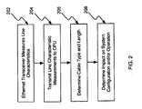
- FIG. 2 illustrates a flowchart of a measurement process.
- FIG. 3 illustrates a cable pair that can be shorted either on the line side or transceiver side of the transformer.
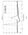
- FIG. 4 illustrates an example of insertion loss measurements for Category 3 and Category 5 cable.
- FIG. 5 illustrates an example of near end crosstalk measurements for Category 3 and Category 5 cable.
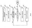
- FIG. 6 illustrates a flowchart of a process for using cable type information.
- Determination of a cable type can have a significant impact on the utility of that cable for a given application. For example, a determination that a cable is of a Category 5 cable type would enable such a cable to be used for a 100BASE-T Fast Ethernet application. Analyzing a cable infrastructure with respect to a cable type is a key part of ensuring that the cable infrastructure is properly utilized. It is therefore a feature of the present invention that a cable infrastructure can be analyzed systematically in an automated fashion.
- FIG. 1 illustrates an embodiment of a system that can measure line characteristics in a network cable.
- measurement system 100 includes PHYs 130-1 to 130-N that are each connected to Ethernet switch 120.
- Each PHY is also connected to CPU 110, although only a single connection from CPU 110 to PHY 130-N is shown for simplicity.
- CPU 110 is incorporated along with Ethernet switch 120 and PHYs 110-1 to 110-N on a single chip.
- Ethernet switch 120 and PHYs 110-1 to 110-N are incorporated on a single chip separate from CPU 110, wherein communication with CPU 110 is enabled via a serial interface.
- the flowchart of FIG. 2 begins at step 202 where a transceiver in PHY 130-N measures line characteristics of a cable coupled to PHY 130-N.
- measurements that enable a determination of insertion loss, cross talk, and cable length are taken during an echo canceller convergence process performed by an echo canceller module under control of CPU 110.
- Line characteristic measurements taken by the transceiver are then transmitted to CPU 110 at step 204.
- the line measurement data is used at step 206 to determine the cable type (e.g., Category 3, 5, 6, 7, etc.).
- the cable length is also determined in addition to the cable type. In various embodiments, these determinations can be performed by CPU 110 or any other system element that is responsible for diagnosing or reporting the cable type.
- the system can then determine its impact on system configuration and/or operation at step 208. Examples of such an impact on system configuration and/or operation are described in greater detail below.
- one or more characteristics such as insertion loss, cross talk, length, etc. of the Ethernet cable are measured to determine a cable type. It should be noted that the measurement of the insertion loss, cross talk, and length of the Ethernet cable represents one example of the characteristics that can be used to estimate the cable type. Other measurements could also be used without departing from the principles of the present invention.
- the system can transmit one, multiple or continuous pulses with pre-determined frequency components into the cable.
- the system can measure the magnitude attenuation and phase distortion, then combine this information with cable length to determine the cable type.
- the link partner can be powered off and the cable pair can be disconnected either on the line side of the transformer or on the opposite (transceiver) side of the transformer.
- the cable pair can be disconnected either on the line side of the transformer or on the opposite (transceiver) side of the transformer.
- almost all of the incidental pulse(s) are reflected back to the transmitting end with the same polarity, and the pulse(s) undergoes insertion loss corresponding to twice the cable length.
- FIG. 4 illustrates an example of insertion loss that can be measured for 100m of Category 3 and Category 5 cable.
- the link partner can be powered off and the cable pair is shorted either on the line side of the transformer or on the opposite (transceiver) side of the transformer. This is illustrated in FIG. 3 where A+ is shorted to A-. In this case, almost all of the incidental pulse(s) are reflected back to the transmitting end with the opposite polarity, and the pulse(s) undergoes insertion loss corresponding to twice the cable length.
- the link partner can be powered off and two cable pairs are disconnected and shorted to the other pair to form a loop (e.g., A+ shorted to B+ and A- shorted to B-). This can happen on either the line side of the transformer or on the opposite (transceiver) side of the transformer. In this case, almost all of the incidental pulse(s) are routed back to the transmitting end in a different pair, and the pulse(s) undergoes insertion loss corresponding to twice the cable length.
- a loop e.g., A+ shorted to B+ and A- shorted to B-
- the link partner can be temporarily powered on to transmit pre-determined pulse(s).
- the pulse(s) undergoes insertion loss corresponding to the cable length.
- Cross talk is similar to insertion loss in that different cable types conform to their own standards defining cross talk over a range of frequencies. Electrical signals traveling down the cable injects noise to adjacent pairs differently with respect to the cable type. The cross talk is a function of both frequency and cable length and is well defined for each cable type.
- the system can transmit one, multiple or continuous pulses with pre-determined frequency components into the cable.
- the system can measure the magnitude attenuation and phase distortion, then combine this information with cable length to determine the cable type.
- NEXT Near-end Cross Talk
- FEXT Far-end Cross Talk
- NEXT the noise injection comes from one or multiple local transmitters
- FEXT the noise injection comes from one or more remote transmitters.
- Either NEXT or FEXT or a combination can be used to determine cable type.
- FIG. 5 illustrates an example of NEXT that can be measured for Category 3 and Category 5 cable.
- cable length can be determined directly using time domain reflectometry (TDR).
- cable length can be determined indirectly based on data generated in the measurement of insertion loss using a round trip of the injected signal.
- the time interval between launching and receiving the pulse(s) is linearly proportional to the cable length. The cable length can then be computed by multiplying the propagation speed with the time interval, then divided by two to account for the round-trip delay.
- the determination of the cable type based on measurements taken by the PHY can be used by the system in various ways.
- the cable type can be used in a diagnostic capacity or as part of a dynamic configuration or operation process.
- One application in which the principles of the present invention can be applied is in the general diagnostic of a cabling infrastructure. For example, it is often important that the cables in a wiring closet, or in a data center be properly identified prior to use. This is a time consuming task if manually performed as hundreds or perhaps thousands of network cables need to be identified. Manual identification is also prone to error if not performed and/or recorded in a systematic fashion.
- the diagnostic tool of the present invention can be applied to a cabling infrastructure to determine the types of cables in a systematic fashion. For example, based on measurements such as insertion loss and cross talk, a diagnostic tool can classify each cable coupled to a chassis. A cable-type report can then be provided to alert a technician as to the nature of the cabling infrastructure. Cables not meeting a certain specification can then be "weeded out" with little effort. It should be noted that the diagnostic tool can also be used to identify whether all segments of a link are of a particular cable type.
- Such a diagnostic tool can be integrated as part of a dynamic configuration or operation process.
- An example of such a dynamic configuration or operation process is illustrated in the flowchart of FIG. 6 .
- an Ethernet transceiver measures line characteristics of a cable connected to a port.
- the line characteristics would include insertion loss, cross talk, and length. Based on these line characteristic measurements, the cable type would then be identified at step 604.
- step 606 it is determined whether the identified cable type meets a basic specification.
- the determination at step 606 can be viewed as a threshold determination that dictates whether or not a given application can proceed over a previously unidentified cable.
- the type of cable need not be identified prior to coupling of that cable to a port. Rather, the measurement of line characteristics after coupling of the cable to the port would enable an identification of the type of cable. This determination could then be used in determining whether the port would be operational or not. If the cable meets the specifications then the port becomes operational. If the cable does not meet the specifications, then the port is disabled. In this case, an alert could also be generated to signal that the cable coupled to the port does not meet the specifications for the given application.
- the identification of the cable type can also be used in a configuration or operation of a port.
- a determination that the cable does not meet the basic specification would lead to a second determination at step 608 of whether a lower cable type would still be useful for that application.
- this second determination is useful in those situations where the stated specifications of a given application are based on worst-case assumptions.
- the stated specifications may be based on a worst-case assumption of the length of the cable.
- a specification designed to support communication on a 100 meter cable may nonetheless work on a lesser quality cable at a shorter distance.
- the determination at step 608 is designed to maximize the utility of the existing cable infrastructure.
- the principles of the present invention allow for an additional analysis to be performed to determine whether a given cable coupled to a port is workable in that particular application installation even though it does not meet a conservative specification.
- the specific elements of the analysis performed at step 608 would be dependent on a given application.
- the analysis could be based on a simple determination of additional factors such as length to qualify a lesser quality cable.
- a cable that did not meet the conservative specification of Category 7 cable could nonetheless be qualified for use if the cable length was less than a predefined threshold (e.g., 50 meters).
- an alert is generated.
- This alert can generally be designed to signal a non-compliance condition on a given port.
- the system can be designed to still attempt to use the cable on that port to see if the cable would support the given application.
- the appropriate configuration of that port is identified at step 610.
- the particular port configuration would be dependent on the particular application.
- the port configuration could simply include a recording of the cable type used on that port.
- the port configuration could also include an adjustment to circuitry or other parameters on that port to accommodate the identified cable type. After the proper configuration is identified, the application can then proceed on that port at step 612.
- various cable characteristics can be used to determine a cable type in an automated systematic manner using measurements taken by a PHY.
- This cable type information can be used to perform a diagnostic of the cable infrastructure or be integrated as part of a dynamic configuration or operation process.
Landscapes
- Engineering & Computer Science (AREA)
- Computer Networks & Wireless Communication (AREA)
- Signal Processing (AREA)
- Monitoring And Testing Of Transmission In General (AREA)
- Small-Scale Networks (AREA)
- Testing Of Short-Circuits, Discontinuities, Leakage, Or Incorrect Line Connections (AREA)
Abstract
Description
- The present invention relates generally to network cabling systems and methods and, more particularly, to the diagnosing of a cabling infrastructure.
- The proliferation of computer networks has lead to the increased deployment of network cables. Initially,
Category 3 cabling having "telephone grade" wire was deployed to support 10BASE-T Ethernet. This inexpensive twisted pair cabling supported runs up to a distance of 100 meters. - As network speeds increased, however,
Category 3 cabling was determined to be incapable of supporting higher transmission rates.Category 5 cabling was then deployed to support technologies such as 100BASE-T Fast Ethernet. Today, Category 6 cabling has emerged as the next evolutionary step in network cabling for the support of Gigabit Ethernet and higher speeds. - Throughout this evolutionary process in transmission rates, network-cabling infrastructures have also been forced to evolve. This evolutionary process in the network-cabling infrastructure has often resulted in newer network cabling being added to the existing infrastructure. The resulting cabling infrastructure therefore resembles a patchwork of differing cable types. Only new installations are likely to have a cabling infrastructure of a single type of cable.
- The typical result of an evolutionary process in cabling deployment is a network-cabling infrastructure that includes multiple generations of network cable types. For example, an office site may have a mix of
Category 3,Category 5, and Category 6 network cables deployed throughout the office site. This results due to the expense of removing older network cables and the continuing utility of such older network cables for a subset of applications. In the end, the mix of network cables presents a significant challenge in ensuring that the right cable type is used for a given application. Typically, the determination of a cable type requires cable testing that is performed manually. This process is both time consuming and expensive. What is needed is a mechanism that enables an automated detection of the network cable type. - A system and/or method for diagnosing a cabling infrastructure using a PHY, substantially as shown in and/or described in connection with at least one of the figures, as set forth more completely in the claims.
- According to an aspect of the invention, a cable diagnosis system comprises:
- a cable detection component in a PHY that measures an electrical characteristic of an Ethernet cable coupled to said PHY;
- a controller that determines a type of said Ethernet cable based on said measured electrical characteristics, said controller being operative to generate a report of said determined Ethernet cable type.
- Advantageously, said cable detection component measures insertion loss of said Ethernet cable.
- Advantageously, said cable detection component measures cross talk of said Ethernet cable.
- Advantageously, said cable detection component measures a length of said Ethernet cable.
- According to an aspect of the invention, an Ethernet port configuration system comprises:
- a cable detection component in a PHY that measures an electrical characteristic of an Ethernet cable coupled to said PHY;
- a controller that determines a type of said Ethernet cable based on said measured electrical characteristics, said controller being operative to configure an aspect of operation of the Ethernet port based on said determined Ethernet cable type.
- Advantageously, said cable detection component measures insertion loss of said Ethernet cable.
- Advantageously, said cable detection component measures cross talk of said Ethernet cable.
- Advantageously, said cable detection component measures a length of said Ethernet cable.
- Advantageously, said controller determines whether the Ethernet port is operational or not.
- Advantageously, said controller changes a parameter on the Ethernet port.
- Advantageously, said controller changes circuitry on the Ethernet port.
- Advantageously, said cable detection component measures a length of said Ethernet cable.
- According to an aspect of the invention, an Ethernet port method comprises:
- upon initialization of an Ethernet port, determining a type of cable coupled to the Ethernet port based on measured electrical characteristics; and
- configuring the Ethernet port based on said determined type of cable.
- Advantageously, said determining comprises measuring insertion loss of said Ethernet cable.
- Advantageously, said determining comprises measuring cross talk of said Ethernet cable.
- Advantageously, said configuring comprises activating the Ethernet port.
- Advantageously, said configuring comprises deactivating the Ethernet port.
- Advantageously, said configuring comprises adjusting a parameter of the Ethernet port.
- Advantageously, said configuring comprises adjusting circuitry on the Ethernet port.
- Advantageously, the method further comprises generating a report of said determined type of cable.
- In order to describe the manner in which the above-recited and other advantages and features of the invention can be obtained, a more particular description of the invention briefly described above will be rendered by reference to specific embodiments thereof which are illustrated in the appended drawings. Understanding that these drawings depict only typical embodiments of the invention and are not therefore to be considered limiting of its scope, the invention will be described and explained with additional specificity and detail through the use of the accompanying drawings in which:
-
FIG. 1 illustrates an embodiment of a system that enables a determination of a cable type using cable characteristic information. -
FIG. 2 illustrates a flowchart of a measurement process. -
FIG. 3 illustrates a cable pair that can be shorted either on the line side or transceiver side of the transformer. -
FIG. 4 illustrates an example of insertion loss measurements forCategory 3 andCategory 5 cable. -
FIG. 5 illustrates an example of near end crosstalk measurements forCategory 3 andCategory 5 cable. -
FIG. 6 illustrates a flowchart of a process for using cable type information. - Various embodiments of the invention are discussed in detail below. While specific implementations are discussed, it should be understood that this is done for illustration purposes only. A person skilled in the relevant art will recognize that other components and configurations may be used without parting from the spirit and scope of the invention.
- Determination of a cable type can have a significant impact on the utility of that cable for a given application. For example, a determination that a cable is of a
Category 5 cable type would enable such a cable to be used for a 100BASE-T Fast Ethernet application. Analyzing a cable infrastructure with respect to a cable type is a key part of ensuring that the cable infrastructure is properly utilized. It is therefore a feature of the present invention that a cable infrastructure can be analyzed systematically in an automated fashion. - In accordance with the present invention, a cable infrastructure is analyzed using measurements of line characteristics that are taken by a PHY.
FIG. 1 illustrates an embodiment of a system that can measure line characteristics in a network cable. As illustrated,measurement system 100 includes PHYs 130-1 to 130-N that are each connected toEthernet switch 120. Each PHY is also connected toCPU 110, although only a single connection fromCPU 110 to PHY 130-N is shown for simplicity. - In one embodiment,
CPU 110 is incorporated along withEthernet switch 120 and PHYs 110-1 to 110-N on a single chip. In another embodiment,Ethernet switch 120 and PHYs 110-1 to 110-N are incorporated on a single chip separate fromCPU 110, wherein communication withCPU 110 is enabled via a serial interface. - To illustrate the operation of
measurement system 100 in implementing the principles of the present invention, reference is now made to the flowchart ofFIG. 2 . As illustrated, the flowchart ofFIG. 2 begins atstep 202 where a transceiver in PHY 130-N measures line characteristics of a cable coupled to PHY 130-N. In one embodiment, measurements that enable a determination of insertion loss, cross talk, and cable length are taken during an echo canceller convergence process performed by an echo canceller module under control ofCPU 110. Line characteristic measurements taken by the transceiver are then transmitted toCPU 110 atstep 204. - The line measurement data is used at
step 206 to determine the cable type (e.g.,Category CPU 110 or any other system element that is responsible for diagnosing or reporting the cable type. After the cable type (and possibly cable length) is determined, the system can then determine its impact on system configuration and/or operation atstep 208. Examples of such an impact on system configuration and/or operation are described in greater detail below. - As noted above, one or more characteristics such as insertion loss, cross talk, length, etc. of the Ethernet cable are measured to determine a cable type. It should be noted that the measurement of the insertion loss, cross talk, and length of the Ethernet cable represents one example of the characteristics that can be used to estimate the cable type. Other measurements could also be used without departing from the principles of the present invention.
- In general, different cable types conform to their own standards defining insertion loss over a range of frequencies. Electrical signals traveling down the cable attenuates differently with respect to the cable type. The insertion loss is a function of both frequency and cable length and is well defined for each cable type. To determine the cable type, the system can transmit one, multiple or continuous pulses with pre-determined frequency components into the cable. At the receiving end, the system can measure the magnitude attenuation and phase distortion, then combine this information with cable length to determine the cable type.
- In one embodiment, the link partner can be powered off and the cable pair can be disconnected either on the line side of the transformer or on the opposite (transceiver) side of the transformer. In this case, almost all of the incidental pulse(s) are reflected back to the transmitting end with the same polarity, and the pulse(s) undergoes insertion loss corresponding to twice the cable length.
FIG. 4 illustrates an example of insertion loss that can be measured for 100m ofCategory 3 andCategory 5 cable. - In another embodiment, the link partner can be powered off and the cable pair is shorted either on the line side of the transformer or on the opposite (transceiver) side of the transformer. This is illustrated in
FIG. 3 where A+ is shorted to A-. In this case, almost all of the incidental pulse(s) are reflected back to the transmitting end with the opposite polarity, and the pulse(s) undergoes insertion loss corresponding to twice the cable length. - In another embodiment, the link partner can be powered off and two cable pairs are disconnected and shorted to the other pair to form a loop (e.g., A+ shorted to B+ and A- shorted to B-). This can happen on either the line side of the transformer or on the opposite (transceiver) side of the transformer. In this case, almost all of the incidental pulse(s) are routed back to the transmitting end in a different pair, and the pulse(s) undergoes insertion loss corresponding to twice the cable length.
- In another embodiment, the link partner can be temporarily powered on to transmit pre-determined pulse(s). In this case, the pulse(s) undergoes insertion loss corresponding to the cable length.
- Cross talk is similar to insertion loss in that different cable types conform to their own standards defining cross talk over a range of frequencies. Electrical signals traveling down the cable injects noise to adjacent pairs differently with respect to the cable type. The cross talk is a function of both frequency and cable length and is well defined for each cable type. To determine the cable type, the system can transmit one, multiple or continuous pulses with pre-determined frequency components into the cable. At the receiving end, the system can measure the magnitude attenuation and phase distortion, then combine this information with cable length to determine the cable type.
- There are two types of cross talk: Near-end Cross Talk (NEXT) and Far-end Cross Talk (FEXT). For NEXT the noise injection comes from one or multiple local transmitters, while for FEXT the noise injection comes from one or more remote transmitters. Either NEXT or FEXT or a combination can be used to determine cable type.
FIG. 5 illustrates an example of NEXT that can be measured forCategory 3 andCategory 5 cable. - In one embodiment, cable length can be determined directly using time domain reflectometry (TDR). In an alternative embodiment, cable length can be determined indirectly based on data generated in the measurement of insertion loss using a round trip of the injected signal. Here, the time interval between launching and receiving the pulse(s) is linearly proportional to the cable length. The cable length can then be computed by multiplying the propagation speed with the time interval, then divided by two to account for the round-trip delay.
- The determination of the cable type based on measurements taken by the PHY can be used by the system in various ways. For example, the cable type can be used in a diagnostic capacity or as part of a dynamic configuration or operation process.
- One application in which the principles of the present invention can be applied is in the general diagnostic of a cabling infrastructure. For example, it is often important that the cables in a wiring closet, or in a data center be properly identified prior to use. This is a time consuming task if manually performed as hundreds or perhaps thousands of network cables need to be identified. Manual identification is also prone to error if not performed and/or recorded in a systematic fashion.
- The diagnostic tool of the present invention can be applied to a cabling infrastructure to determine the types of cables in a systematic fashion. For example, based on measurements such as insertion loss and cross talk, a diagnostic tool can classify each cable coupled to a chassis. A cable-type report can then be provided to alert a technician as to the nature of the cabling infrastructure. Cables not meeting a certain specification can then be "weeded out" with little effort. It should be noted that the diagnostic tool can also be used to identify whether all segments of a link are of a particular cable type.
- More generally, it is a feature of the present invention that such a diagnostic tool can be integrated as part of a dynamic configuration or operation process. An example of such a dynamic configuration or operation process is illustrated in the flowchart of
FIG. 6 . - As illustrated the process begins at
step 602, where an Ethernet transceiver measures line characteristics of a cable connected to a port. In one embodiment, the line characteristics would include insertion loss, cross talk, and length. Based on these line characteristic measurements, the cable type would then be identified atstep 604. Next, atstep 606, it is determined whether the identified cable type meets a basic specification. - For example, consider an application such as 10GBASE-T as defined by IEEE 802.3an. This specification includes a minimal requirement for cabling that states that Category 7 Ethernet cabling should be used. In this example, a determination that the cable type was Category 7 or better would indicate that the cable connected to the port is within the stated cable specifications. This Category 7 or better determination would then indicate, at
step 612, that 10GBASE-T communication could proceed over the cable connected to that particular port. - In general, the determination at
step 606 can be viewed as a threshold determination that dictates whether or not a given application can proceed over a previously unidentified cable. In other words, the type of cable need not be identified prior to coupling of that cable to a port. Rather, the measurement of line characteristics after coupling of the cable to the port would enable an identification of the type of cable. This determination could then be used in determining whether the port would be operational or not. If the cable meets the specifications then the port becomes operational. If the cable does not meet the specifications, then the port is disabled. In this case, an alert could also be generated to signal that the cable coupled to the port does not meet the specifications for the given application. - In one embodiment, the identification of the cable type can also be used in a configuration or operation of a port. In this case, a determination that the cable does not meet the basic specification would lead to a second determination at
step 608 of whether a lower cable type would still be useful for that application. In general, this second determination is useful in those situations where the stated specifications of a given application are based on worst-case assumptions. For example, the stated specifications may be based on a worst-case assumption of the length of the cable. Here, a specification designed to support communication on a 100 meter cable may nonetheless work on a lesser quality cable at a shorter distance. - Recognizing this possibility, the determination at
step 608 is designed to maximize the utility of the existing cable infrastructure. Instead of relying on overly broad characterizations of cable performance based solely on cable type, the principles of the present invention allow for an additional analysis to be performed to determine whether a given cable coupled to a port is workable in that particular application installation even though it does not meet a conservative specification. - As would be appreciated, the specific elements of the analysis performed at
step 608 would be dependent on a given application. In a simple example, the analysis could be based on a simple determination of additional factors such as length to qualify a lesser quality cable. Here, a cable that did not meet the conservative specification of Category 7 cable, could nonetheless be qualified for use if the cable length was less than a predefined threshold (e.g., 50 meters). - Referring again to the flow chart of
FIG. 6 , if the determination atstep 608 still indicates that the cable is not useful for a given application, then an alert is generated. This alert can generally be designed to signal a non-compliance condition on a given port. In one embodiment, the system can be designed to still attempt to use the cable on that port to see if the cable would support the given application. - If the determination at
step 608 indicates that the cable not meeting the stated specification is nonetheless useful for a given application, then the appropriate configuration of that port is identified atstep 610. As would be appreciated, the particular port configuration would be dependent on the particular application. In one example, the port configuration could simply include a recording of the cable type used on that port. In another example, the port configuration could also include an adjustment to circuitry or other parameters on that port to accommodate the identified cable type. After the proper configuration is identified, the application can then proceed on that port atstep 612. - As has been described, various cable characteristics can be used to determine a cable type in an automated systematic manner using measurements taken by a PHY. This cable type information can be used to perform a diagnostic of the cable infrastructure or be integrated as part of a dynamic configuration or operation process.
- These and other aspects of the present invention will become apparent to those skilled in the art by a review of the preceding detailed description. Although a number of salient features of the present invention have been described above, the invention is capable of other embodiments and of being practiced and carried out in various ways that would be apparent to one of ordinary skill in the art after reading the disclosed invention, therefore the above description should not be considered to be exclusive of these other embodiments. Also, it is to be understood that the phraseology and terminology employed herein are for the purposes of description and should not be regarded as limiting.
Claims (10)
- A cable diagnosis system, comprising:a cable detection component in a PHY that measures an electrical characteristic of an Ethernet cable coupled to said PHY;a controller that determines a type of said Ethernet cable based on said measured electrical characteristics, said controller being operative to generate a report of said determined Ethernet cable type.
- The cable diagnosis system of claim 1, wherein said cable detection component measures insertion loss of said Ethernet cable.
- The cable diagnosis system of claim 1, wherein said cable detection component measures cross talk of said Ethernet cable.
- The cable diagnosis system of claim 1, wherein said cable detection component measures a length of said Ethernet cable.
- An Ethernet port configuration system, comprising:a cable detection component in a PHY that measures an electrical characteristic of an Ethernet cable coupled to said PHY;a controller that determines a type of said Ethernet cable based on said measured electrical characteristics, said controller being operative to configure an aspect of operation of the Ethernet port based on said determined Ethernet cable type.
- The Ethernet port configuration system of claim 5, wherein said cable detection component measures insertion loss of said Ethernet cable.
- The Ethernet port configuration system of claim 5, wherein said cable detection component measures cross talk of said Ethernet cable.
- An Ethernet port method, comprising:upon initialization of an Ethernet port, determining a type of cable coupled to the Ethernet port based on measured electrical characteristics; andconfiguring the Ethernet port based on said determined type of cable.
- The method of claim 8, wherein said determining comprises measuring insertion loss of said Ethernet cable.
- The method of claim 8, wherein said determining comprises measuring cross talk of said Ethernet cable.
Applications Claiming Priority (2)
| Application Number | Priority Date | Filing Date | Title |
|---|---|---|---|
| US85333006P | 2006-12-19 | 2006-12-19 | |
| US11/654,012 US7738387B2 (en) | 2007-01-17 | 2007-01-17 | System and method for diagnosing a cabling infrastructure using a PHY |
Publications (2)
| Publication Number | Publication Date |
|---|---|
| EP1936875A1 true EP1936875A1 (en) | 2008-06-25 |
| EP1936875B1 EP1936875B1 (en) | 2016-03-09 |
Family
ID=38698373
Family Applications (1)
| Application Number | Title | Priority Date | Filing Date |
|---|---|---|---|
| EP07021735.1A Active EP1936875B1 (en) | 2006-12-19 | 2007-11-08 | System and method for diagnosing a cabling infrastructure using a PHY |
Country Status (4)
| Country | Link |
|---|---|
| EP (1) | EP1936875B1 (en) |
| KR (1) | KR100969222B1 (en) |
| CN (1) | CN102098178B (en) |
| TW (1) | TWI389503B (en) |
Cited By (1)
| Publication number | Priority date | Publication date | Assignee | Title |
|---|---|---|---|---|
| EP2482490A1 (en) * | 2011-01-31 | 2012-08-01 | Alcatel Lucent | Device and method for improving home network infrastructure |
Families Citing this family (3)
| Publication number | Priority date | Publication date | Assignee | Title |
|---|---|---|---|---|
| US9231655B2 (en) * | 2012-04-06 | 2016-01-05 | Broadcom Corporation | System and method for power control in a physical layer device |
| CN111355778B (en) * | 2020-02-17 | 2022-07-05 | 威马智慧出行科技(上海)有限公司 | Diagnostic device, vehicle-end device and diagnostic method |
| CN115941465B (en) * | 2022-12-02 | 2025-01-07 | 京东科技信息技术有限公司 | Network card configuration method, device, electronic equipment and computer readable storage medium |
Citations (4)
| Publication number | Priority date | Publication date | Assignee | Title |
|---|---|---|---|---|
| US20040251913A1 (en) * | 2003-06-11 | 2004-12-16 | Broadcom Corporation | Cable diagnostics using time domain reflectometry and applications using the same |
| WO2005117337A1 (en) * | 2004-05-20 | 2005-12-08 | Cisco Technology, Inc. | Methods and apparatus for provisioning phantom power to remote devices based on admission control |
| WO2006052360A1 (en) * | 2004-11-03 | 2006-05-18 | Cisco Technology, Inc. | Phy-based current imbalance compensation for magnetics in a wired data telecommunications network |
| US7075283B1 (en) * | 2002-06-07 | 2006-07-11 | Marvell International Ltd. | Cable tester |
Family Cites Families (2)
| Publication number | Priority date | Publication date | Assignee | Title |
|---|---|---|---|---|
| NO984777L (en) * | 1998-04-06 | 1999-10-05 | Cable As V Knut Foseide Safety | Theft Alert Cable |
| US6654840B1 (en) * | 1998-05-19 | 2003-11-25 | Sega Enterprises, Ltd. | Connection cable identification mechanism |
-
2007
- 2007-11-08 EP EP07021735.1A patent/EP1936875B1/en active Active
- 2007-12-14 CN CN201110037507.0A patent/CN102098178B/en not_active Expired - Fee Related
- 2007-12-18 KR KR1020070133807A patent/KR100969222B1/en not_active Expired - Fee Related
- 2007-12-19 TW TW096148703A patent/TWI389503B/en not_active IP Right Cessation
Patent Citations (4)
| Publication number | Priority date | Publication date | Assignee | Title |
|---|---|---|---|---|
| US7075283B1 (en) * | 2002-06-07 | 2006-07-11 | Marvell International Ltd. | Cable tester |
| US20040251913A1 (en) * | 2003-06-11 | 2004-12-16 | Broadcom Corporation | Cable diagnostics using time domain reflectometry and applications using the same |
| WO2005117337A1 (en) * | 2004-05-20 | 2005-12-08 | Cisco Technology, Inc. | Methods and apparatus for provisioning phantom power to remote devices based on admission control |
| WO2006052360A1 (en) * | 2004-11-03 | 2006-05-18 | Cisco Technology, Inc. | Phy-based current imbalance compensation for magnetics in a wired data telecommunications network |
Cited By (5)
| Publication number | Priority date | Publication date | Assignee | Title |
|---|---|---|---|---|
| EP2482490A1 (en) * | 2011-01-31 | 2012-08-01 | Alcatel Lucent | Device and method for improving home network infrastructure |
| WO2012104165A1 (en) * | 2011-01-31 | 2012-08-09 | Alcatel Lucent | Device and method for improving home network infrastructure |
| CN103339900A (en) * | 2011-01-31 | 2013-10-02 | 阿尔卡特朗讯 | Device and method for improving home network infrastructure |
| KR20130129432A (en) * | 2011-01-31 | 2013-11-28 | 알까뗄 루슨트 | Device and method for improving home network infrastructure |
| US9450832B2 (en) | 2011-01-31 | 2016-09-20 | Alcatel Lucent | Device and method for improving home network infrastructure |
Also Published As
| Publication number | Publication date |
|---|---|
| CN102098178B (en) | 2014-02-19 |
| KR20080057197A (en) | 2008-06-24 |
| TWI389503B (en) | 2013-03-11 |
| EP1936875B1 (en) | 2016-03-09 |
| HK1158401A1 (en) | 2012-07-13 |
| CN102098178A (en) | 2011-06-15 |
| TW200845652A (en) | 2008-11-16 |
| KR100969222B1 (en) | 2010-07-09 |
Similar Documents
| Publication | Publication Date | Title |
|---|---|---|
| US7738387B2 (en) | System and method for diagnosing a cabling infrastructure using a PHY | |
| CN101345553B (en) | Cable diagnostic system and method and system for Ethernet port configuration | |
| US7906973B1 (en) | Cable tester | |
| US7190172B1 (en) | Cable tester | |
| EP0675607B1 (en) | Cable crosstalk measurement system | |
| US7884615B1 (en) | Cable tester | |
| US7068044B1 (en) | Cable tester | |
| US7403018B1 (en) | Cable tester | |
| US6995551B1 (en) | Cable tester with insertion loss estimator | |
| US7576548B1 (en) | Cable tester | |
| US7808247B1 (en) | Fast cable tester | |
| US7683628B1 (en) | Cable tester | |
| US8416699B1 (en) | Cable tester | |
| EP1585301A1 (en) | Apparatus and method for testing and fault isolation in a communication network | |
| US7075283B1 (en) | Cable tester | |
| EP1936875B1 (en) | System and method for diagnosing a cabling infrastructure using a PHY | |
| US7019533B1 (en) | Cable tester | |
| US8619604B2 (en) | System and method for auto 10BASE-T/10BASE-Te selection based on cable characteristics | |
| HK1158401B (en) | Systen for diagnosing cable and method and system for port configuration of ethernet |
Legal Events
| Date | Code | Title | Description |
|---|---|---|---|
| PUAI | Public reference made under article 153(3) epc to a published international application that has entered the european phase |
Free format text: ORIGINAL CODE: 0009012 |
|
| AK | Designated contracting states |
Kind code of ref document: A1 Designated state(s): AT BE BG CH CY CZ DE DK EE ES FI FR GB GR HU IE IS IT LI LT LU LV MC MT NL PL PT RO SE SI SK TR |
|
| AX | Request for extension of the european patent |
Extension state: AL BA HR MK RS |
|
| 17P | Request for examination filed |
Effective date: 20081229 |
|
| AKX | Designation fees paid |
Designated state(s): DE FR GB |
|
| 17Q | First examination report despatched |
Effective date: 20090204 |
|
| GRAP | Despatch of communication of intention to grant a patent |
Free format text: ORIGINAL CODE: EPIDOSNIGR1 |
|
| INTG | Intention to grant announced |
Effective date: 20150922 |
|
| GRAS | Grant fee paid |
Free format text: ORIGINAL CODE: EPIDOSNIGR3 |
|
| GRAA | (expected) grant |
Free format text: ORIGINAL CODE: 0009210 |
|
| AK | Designated contracting states |
Kind code of ref document: B1 Designated state(s): DE FR GB |
|
| REG | Reference to a national code |
Ref country code: GB Ref legal event code: FG4D |
|
| REG | Reference to a national code |
Ref country code: DE Ref legal event code: R096 Ref document number: 602007045088 Country of ref document: DE |
|
| REG | Reference to a national code |
Ref country code: DE Ref legal event code: R097 Ref document number: 602007045088 Country of ref document: DE |
|
| PLBE | No opposition filed within time limit |
Free format text: ORIGINAL CODE: 0009261 |
|
| STAA | Information on the status of an ep patent application or granted ep patent |
Free format text: STATUS: NO OPPOSITION FILED WITHIN TIME LIMIT |
|
| 26N | No opposition filed |
Effective date: 20161212 |
|
| REG | Reference to a national code |
Ref country code: DE Ref legal event code: R082 Ref document number: 602007045088 Country of ref document: DE Representative=s name: BOSCH JEHLE PATENTANWALTSGESELLSCHAFT MBH, DE Ref country code: DE Ref legal event code: R081 Ref document number: 602007045088 Country of ref document: DE Owner name: AVAGO TECHNOLOGIES INTERNATIONAL SALES PTE. LT, SG Free format text: FORMER OWNER: BROADCOM CORPORATION, IRVINE, CALIF., US Ref country code: DE Ref legal event code: R081 Ref document number: 602007045088 Country of ref document: DE Owner name: AVAGO TECHNOLOGIES GENERAL IP (SINGAPORE) PTE., SG Free format text: FORMER OWNER: BROADCOM CORPORATION, IRVINE, CALIF., US |
|
| GBPC | Gb: european patent ceased through non-payment of renewal fee |
Effective date: 20161108 |
|
| REG | Reference to a national code |
Ref country code: FR Ref legal event code: ST Effective date: 20170731 |
|
| PG25 | Lapsed in a contracting state [announced via postgrant information from national office to epo] |
Ref country code: FR Free format text: LAPSE BECAUSE OF NON-PAYMENT OF DUE FEES Effective date: 20161130 |
|
| PG25 | Lapsed in a contracting state [announced via postgrant information from national office to epo] |
Ref country code: GB Free format text: LAPSE BECAUSE OF NON-PAYMENT OF DUE FEES Effective date: 20161108 |
|
| REG | Reference to a national code |
Ref country code: DE Ref legal event code: R082 Ref document number: 602007045088 Country of ref document: DE Representative=s name: BOSCH JEHLE PATENTANWALTSGESELLSCHAFT MBH, DE Ref country code: DE Ref legal event code: R081 Ref document number: 602007045088 Country of ref document: DE Owner name: AVAGO TECHNOLOGIES INTERNATIONAL SALES PTE. LT, SG Free format text: FORMER OWNER: AVAGO TECHNOLOGIES GENERAL IP (SINGAPORE) PTE. LTD., SINGAPORE, SG |
|
| PGFP | Annual fee paid to national office [announced via postgrant information from national office to epo] |
Ref country code: DE Payment date: 20251112 Year of fee payment: 19 |