EP1936830A1 - Mobile communication terminal and transmission power controlling method - Google Patents
Mobile communication terminal and transmission power controlling method Download PDFInfo
- Publication number
- EP1936830A1 EP1936830A1 EP20070024496 EP07024496A EP1936830A1 EP 1936830 A1 EP1936830 A1 EP 1936830A1 EP 20070024496 EP20070024496 EP 20070024496 EP 07024496 A EP07024496 A EP 07024496A EP 1936830 A1 EP1936830 A1 EP 1936830A1
- Authority
- EP
- European Patent Office
- Prior art keywords
- reception quality
- mobile communication
- communication terminal
- transmission power
- reception
- Prior art date
- Legal status (The legal status is an assumption and is not a legal conclusion. Google has not performed a legal analysis and makes no representation as to the accuracy of the status listed.)
- Granted
Links
Images


Classifications
-
- H—ELECTRICITY
- H04—ELECTRIC COMMUNICATION TECHNIQUE
- H04W—WIRELESS COMMUNICATION NETWORKS
- H04W52/00—Power management, e.g. Transmission Power Control [TPC] or power classes
- H04W52/04—Transmission power control [TPC]
- H04W52/06—TPC algorithms
- H04W52/12—Outer and inner loops
-
- H—ELECTRICITY
- H04—ELECTRIC COMMUNICATION TECHNIQUE
- H04W—WIRELESS COMMUNICATION NETWORKS
- H04W24/00—Supervisory, monitoring or testing arrangements
-
- H—ELECTRICITY
- H04—ELECTRIC COMMUNICATION TECHNIQUE
- H04W—WIRELESS COMMUNICATION NETWORKS
- H04W28/00—Network traffic management; Network resource management
- H04W28/16—Central resource management; Negotiation of resources or communication parameters, e.g. negotiating bandwidth or QoS [Quality of Service]
- H04W28/24—Negotiating SLA [Service Level Agreement]; Negotiating QoS [Quality of Service]
-
- H—ELECTRICITY
- H04—ELECTRIC COMMUNICATION TECHNIQUE
- H04W—WIRELESS COMMUNICATION NETWORKS
- H04W52/00—Power management, e.g. Transmission Power Control [TPC] or power classes
- H04W52/04—Transmission power control [TPC]
- H04W52/18—TPC being performed according to specific parameters
- H04W52/28—TPC being performed according to specific parameters using user profile, e.g. mobile speed, priority or network state, e.g. standby, idle or non-transmission
- H04W52/282—TPC being performed according to specific parameters using user profile, e.g. mobile speed, priority or network state, e.g. standby, idle or non-transmission taking into account the speed of the mobile
-
- H—ELECTRICITY
- H04—ELECTRIC COMMUNICATION TECHNIQUE
- H04W—WIRELESS COMMUNICATION NETWORKS
- H04W8/00—Network data management
- H04W8/22—Processing or transfer of terminal data, e.g. status or physical capabilities
-
- H—ELECTRICITY
- H04—ELECTRIC COMMUNICATION TECHNIQUE
- H04W—WIRELESS COMMUNICATION NETWORKS
- H04W88/00—Devices specially adapted for wireless communication networks, e.g. terminals, base stations or access point devices
- H04W88/02—Terminal devices
- H04W88/021—Terminal devices adapted for Wireless Local Loop operation
Definitions
- the present invention relates to a mobile communication terminal capable of controlling the transmission power of a base station, and also relates to a transmission power controlling method.
- multiple mobile communication terminals that communicate with a base station simultaneously share the same frequency bands.
- An example of such communication systems is a CDMA communication system.
- transmission power control in which the transmission power of the mobile terminals and that of the base station are controlled, is a specific measure conventionally employed for the purpose.
- a closed-loop power transmission control which is a specific example of the transmission power control, includes inner-loop control and outer-loop control.
- the mobile communication terminal measures the instantaneous reception quality of a received signal that has been transmitted from the base station, and compares the measured instantaneous reception quality with a target value of the instantaneous reception quality. Then, the transmission power of the base station is controlled using the comparison result. As a result, the reception power of the mobile communication terminal for the signal transmitted from the base station is kept constant, and stable radio communications are accomplished.
- One of the generally used indicators of the instantaneous reception quality is the signal to interference power ratio (SIR).
- the reception quality is measured for a longer period of time than in the case of the inner-loop control.
- the long-term reception quality thus measured in the outer-loop control is compared with a target value of the long-term reception quality. Then, the target value of the instantaneous reception quality is updated using the comparison result.
- One of the generally used indicators of the long-term reception quality is the block error rate (BLER).
- the length of the period for measuring each of the instantaneous reception quality and the long-term reception quality is normally fixed to a certain value. Such fixation is not suitable for tracking the fading fluctuation, which is a rapid change in the receiving power on the mobile communication terminal side. Such drastic change occurs when the mobile communication terminal moves, or when the radio wave is reflected by a building, or the like.
- Methods for addressing the fading fluctuation have been proposed by controlling the length of the period for measuring the received signal code power (RSCP) and the interference signal code power (ISCP), both of which is used to measure the SIR. Refer to Japanese Patent Application Laid-open Publication No. 2005-167710 .
- the reception quality is measured over a long period of time. Consequently, the updating cycle of the target value for the instantaneous reception quality, which is the length of time that has been passed since the last updating of the target value for the instantaneous reception quality until the current time of updating the value, becomes longer.
- Such a long cycle on which the target value for the instantaneous reception quality is updated may cause an inconvenience.
- An inconvenience occurs in a situation where the wireless communication environment is likely to change, that is, the mobile communication terminal moves at a high speed.
- a rapid deterioration of the wireless communication environment causes a disconnection of the communications.
- the outer-loop control is incapable of increasing the target value for the instantaneous reception quality before the communications are disconnected.
- the present invention has been made in consideration for the above-described problems inherent in the prior art. It is an object of the present invention to provide a mobile communication terminal and a transmission power controlling method to make the disconnection of the communications less likely to occur even in a rapidly changing wireless communication environment.
- a first aspect of the present invention provides a mobile communication terminal.
- the mobile communication terminal includes a transmission power controller configured to measure a first reception quality of a signal received from a base station, and to control a transmission power of the base station in accordance with a result of comparison between the first reception quality and a target value of the first reception quality.
- a target value updater configured to measure a second reception quality of the received signal, and to update the target value in accordance with a measurement result of the second reception quality.
- the mobile communication terminal includes a measurement controller configured to acquire a moving state of the mobile communication terminal to which the measurement controller belongs, and, based on the acquired moving state, to control a period of measuring the second reception quality and a cycle of updating the target value.
- the mobile communication terminal controls the period of measuring the second reception quality and the cycle of updating the target value of the first reception quality in accordance with the moving state of the same mobile communication terminal. Accordingly, a disconnection of communications is made less likely to occur even in a rapidly changing wireless communication environment.
- a second aspect of the present invention provides the mobile communication terminal according to the first aspect.
- the first reception quality is a reception quality used in an inner-loop control
- the second reception quality is a reception quality used in an outer-loop control.
- the mobile communication terminal controls the period of measuring the reception quality used in the outer-loop control and the cycle of updating the target value of the reception quality used in the inner-loop control in accordance with the moving state of the same mobile communication terminal. Accordingly, a disconnection of communications is made less likely to occur even in a rapidly changing wireless communication environment.
- a third aspect of the present invention provides the mobile communication terminal according to the first aspect.
- the first reception quality is an instantaneous reception quality
- the second reception quality is a long-term reception quality.
- the long-term reception quality is a reception quality measured over a longer period of time than a period of time over which the instantaneous reception quality is measured.
- the mobile communication terminal controls the period of measuring the instantaneous reception quality and the cycle of updating the target value of the long-term reception quality in accordance with the moving state of the same mobile communication terminal. Accordingly, a disconnection of communications is made less likely to occur even in a rapidly changing wireless communication environment.
- a fourth aspect of the present invention provides the mobile communication terminal according to the first aspect.
- the measurement controller is configured to acquire, as the moving state, a moving speed of the mobile communication terminal to which the measurement controller belongs.
- a fifth aspect of the present invention provides the mobile communication terminal according to the first aspect.
- the transmission power controller is configured to transmit, to the base station, a control command to control the transmission power of the base station.
- the measurement controller is configured further to control a period of measuring the first reception quality and to control a cycle of transmitting the control command.
- a sixth aspect of the present invention provides the mobile communication terminal according to the first aspect.
- the measurement controller is configured to change the period of measuring and the cycle of updating only on condition that a moving state acquired newly on this occasion differs from a moving state having been acquired on the previous occasion.
- a seventh aspect of the present invention provides a transmission power controlling method.
- the controlling method includes a step of measuring a first reception quality of a signal received from a base station, and controlling a transmission power of the base station in accordance with a result of comparison between the first reception quality and a target value of the first reception quality.
- the controlling method also includes a step of measuring a second reception quality of the received signal, and updating the target value in accordance with a measurement result of the second reception quality.
- the controlling method includes a step of acquiring a moving state of a mobile communication terminal that employs the controlling method, and, based on the acquired moving state, controlling a period of measuring the second reception quality and a cycle of updating the target value.
- the mobile communication terminal and the transmission power controlling method that are provided according to the present invention can make the disconnection of the communications less likely to occur even in a rapidly changing wireless communication environment.
- the reception-BLER measurement period is shortened.
- the reception BLER is thus measured with higher accuracy.
- the cycle of updating the target SIR is shortened. The tracking performance to the wireless communication environment is thus improved.
- the mobile terminal 1 in this embodiment controls the reception-SIR measurement period and the cycle of generating control commands (transmission cycle) in accordance with the moving speed of the mobile communication terminal 1. Accordingly, the disconnection of the communications is made further less likely to occur even in a rapidly changing wireless communication environment.
- the reception-SIR measurement period is shortened.
- the reception SIR is thus measured with higher accuracy
- the cycle of generating control commands is shortened.
- the tracking performance to the wireless communication environment is thus improved.
- the setting parameters in this embodiment are changed only when the newly acquired moving speed differs from the previously-acquired one. To put it other way, the setting parameters are not changed when the newly acquired moving speed is equivalent to the previously-acquired one. Consequently, the load for processing on the mobile communication terminal 1 and the increase in the power consumption can be reduced.
- the setting parameters in the above-described embodiment are calculated linearly (using a linear function) in relation to the moving speed of the mobile communication terminal 1.
- the setting parameters are, as Fig. 5 shows, calculated non-linearly.
- the setting parameters are calculated non-linearly, Accordingly, as the mobile communication terminal 1 moves faster, the setting-parameter cycle is shortened sharply.
- the setting-parameter cycle y 2 at the speed of 60 km/h in Fig. 5 has a value significantly smaller than the setting-parameter cycle y 1 at the speed of 60 km/h in Fig. 3 .
- non-linear calculation of the setting parameters can improve the measurement accuracy of the reception SIR and the reception BLER when the moving speed of the mobile communication terminal 1 increases.
- the tracking performance to the wireless communication environment is thus improved.
- the setting parameters are not calculated from the moving speed of the mobile communication terminal 1. Instead, setting parameters corresponding to the moving speed are acquired from a table that has been provided in advance.
- Fig. 6 is a configuration example of a table that makes the moving speed and the setting parameters correspond to each other.
- the table shown in Fig. 6 includes such items as "moving state,” “threshold for determining speed,” and "setting parameters.”
- Thresholds for determining speed are defined to classify these steps of moving state. Different values for each of the setting parameters (SIR measurement period and BLER measurement period in this example) are defined in accordance with the steps of moving state.
- Fig. 7 is a flowchart illustrating the flow of operations of the mobile communication terminal 1 according to this modified example.
- the setting parameters are acquired from the table in step S203 so as to correspond to the moving speed v t that has been obtained in step S201.
- the operations shown in the flowchart of Fig. 7 differs from the operations shown in the flowchart of Fig. 4 .
- the setting parameters are not calculated from the moving speed of the mobile communication terminal 1, Instead, setting parameters corresponding to the moving speed are acquired from the table that has been provided in advance. Consequently, the load for processing on the mobile communication terminal 1 can be reduced in this modified example from the load in the case of the above-described embodiment.
- the moving-speed acquiring unit 1051 is configured to acquire the moving speed as the moving state of the mobile communication terminal 1, but what is to be acquired in the present invention is not limited to the moving speed.
- the moving-speed acquiring unit 1051 may be configured to acquire information indicating the state of the mobile communication terminal 1, that is, information on whether the mobile communication terminal is in a stationary state or is moving. In this case, the load for processing on the mobile communication terminal 1 can be reduced significantly.
- the long-term reception quality measured in the above-described embodiment is the reception BLER, but the quality to be measured for this purpose in the present invention is not limited to the reception BLER.
- the reception bit error rate (reception BER) is to be measured.
- the mobile communication system of the above-described embodiment is a system of a CDMA, but the system of the present invention is not limited to a CDMA system.
- the above-described transmission power controlling method is applicable to a mobile communication system of a different type.
Landscapes
- Engineering & Computer Science (AREA)
- Computer Networks & Wireless Communication (AREA)
- Signal Processing (AREA)
- Quality & Reliability (AREA)
- Databases & Information Systems (AREA)
- Mobile Radio Communication Systems (AREA)
Abstract
Description
- This application is based upon and claims the benefit of priority from prior
Japanese Patent Application P2006-340504 filed on December 18, 2006 - The present invention relates to a mobile communication terminal capable of controlling the transmission power of a base station, and also relates to a transmission power controlling method.
- In some mobile communication systems, multiple mobile communication terminals that communicate with a base station simultaneously share the same frequency bands. An example of such communication systems is a CDMA communication system. In such a system, a measure has to be taken to prevent the interference among the mobile communication terminals, and "transmission power control," in which the transmission power of the mobile terminals and that of the base station are controlled, is a specific measure conventionally employed for the purpose. A closed-loop power transmission control, which is a specific example of the transmission power control, includes inner-loop control and outer-loop control.
- In the inner-loop control, the mobile communication terminal measures the instantaneous reception quality of a received signal that has been transmitted from the base station, and compares the measured instantaneous reception quality with a target value of the instantaneous reception quality. Then, the transmission power of the base station is controlled using the comparison result. As a result, the reception power of the mobile communication terminal for the signal transmitted from the base station is kept constant, and stable radio communications are accomplished. One of the generally used indicators of the instantaneous reception quality is the signal to interference power ratio (SIR).
- In the outer-loop control, on the other hand, the reception quality is measured for a longer period of time than in the case of the inner-loop control. The long-term reception quality thus measured in the outer-loop control is compared with a target value of the long-term reception quality. Then, the target value of the instantaneous reception quality is updated using the comparison result. One of the generally used indicators of the long-term reception quality is the block error rate (BLER).
- The length of the period for measuring each of the instantaneous reception quality and the long-term reception quality is normally fixed to a certain value. Such fixation is not suitable for tracking the fading fluctuation, which is a rapid change in the receiving power on the mobile communication terminal side. Such drastic change occurs when the mobile communication terminal moves, or when the radio wave is reflected by a building, or the like. Methods for addressing the fading fluctuation have been proposed by controlling the length of the period for measuring the received signal code power (RSCP) and the interference signal code power (ISCP), both of which is used to measure the SIR. Refer to
Japanese Patent Application Laid-open Publication No. 2005-167710 - As has been described above, in the outer-loop control, the reception quality is measured over a long period of time. Consequently, the updating cycle of the target value for the instantaneous reception quality, which is the length of time that has been passed since the last updating of the target value for the instantaneous reception quality until the current time of updating the value, becomes longer.
- Such a long cycle on which the target value for the instantaneous reception quality is updated may cause an inconvenience. An inconvenience occurs in a situation where the wireless communication environment is likely to change, that is, the mobile communication terminal moves at a high speed. To be more specific, a rapid deterioration of the wireless communication environment causes a disconnection of the communications. The outer-loop control is incapable of increasing the target value for the instantaneous reception quality before the communications are disconnected.
- The present invention has been made in consideration for the above-described problems inherent in the prior art. It is an object of the present invention to provide a mobile communication terminal and a transmission power controlling method to make the disconnection of the communications less likely to occur even in a rapidly changing wireless communication environment.
- To accomplish the object, a first aspect of the present invention provides a mobile communication terminal. The mobile communication terminal includes a transmission power controller configured to measure a first reception quality of a signal received from a base station, and to control a transmission power of the base station in accordance with a result of comparison between the first reception quality and a target value of the first reception quality. Also included is a target value updater configured to measure a second reception quality of the received signal, and to update the target value in accordance with a measurement result of the second reception quality. In addition, the mobile communication terminal includes a measurement controller configured to acquire a moving state of the mobile communication terminal to which the measurement controller belongs, and, based on the acquired moving state, to control a period of measuring the second reception quality and a cycle of updating the target value.
- The mobile communication terminal according to the first aspect controls the period of measuring the second reception quality and the cycle of updating the target value of the first reception quality in accordance with the moving state of the same mobile communication terminal. Accordingly, a disconnection of communications is made less likely to occur even in a rapidly changing wireless communication environment.
- A second aspect of the present invention provides the mobile communication terminal according to the first aspect. In the terminal provided in the second aspect, the first reception quality is a reception quality used in an inner-loop control, and the second reception quality is a reception quality used in an outer-loop control.
- The mobile communication terminal according to the second aspect controls the period of measuring the reception quality used in the outer-loop control and the cycle of updating the target value of the reception quality used in the inner-loop control in accordance with the moving state of the same mobile communication terminal. Accordingly, a disconnection of communications is made less likely to occur even in a rapidly changing wireless communication environment.
- A third aspect of the present invention provides the mobile communication terminal according to the first aspect. In the terminal provided in the third aspect, the first reception quality is an instantaneous reception quality, and the second reception quality is a long-term reception quality. The long-term reception quality is a reception quality measured over a longer period of time than a period of time over which the instantaneous reception quality is measured.
- The mobile communication terminal according to the third aspect controls the period of measuring the instantaneous reception quality and the cycle of updating the target value of the long-term reception quality in accordance with the moving state of the same mobile communication terminal. Accordingly, a disconnection of communications is made less likely to occur even in a rapidly changing wireless communication environment.
- A fourth aspect of the present invention provides the mobile communication terminal according to the first aspect. In the terminal provided in the fourth aspect, the measurement controller is configured to acquire, as the moving state, a moving speed of the mobile communication terminal to which the measurement controller belongs.
- A fifth aspect of the present invention provides the mobile communication terminal according to the first aspect. In the terminal provided in the fifth aspect, the transmission power controller is configured to transmit, to the base station, a control command to control the transmission power of the base station. In addition, the measurement controller is configured further to control a period of measuring the first reception quality and to control a cycle of transmitting the control command.
- A sixth aspect of the present invention provides the mobile communication terminal according to the first aspect. In the terminal provided in the sixth aspect, the measurement controller is configured to change the period of measuring and the cycle of updating only on condition that a moving state acquired newly on this occasion differs from a moving state having been acquired on the previous occasion.
- A seventh aspect of the present invention provides a transmission power controlling method. The controlling method includes a step of measuring a first reception quality of a signal received from a base station, and controlling a transmission power of the base station in accordance with a result of comparison between the first reception quality and a target value of the first reception quality. The controlling method also includes a step of measuring a second reception quality of the received signal, and updating the target value in accordance with a measurement result of the second reception quality. In addition the controlling method includes a step of acquiring a moving state of a mobile communication terminal that employs the controlling method, and, based on the acquired moving state, controlling a period of measuring the second reception quality and a cycle of updating the target value.
- The mobile communication terminal and the transmission power controlling method that are provided according to the present invention can make the disconnection of the communications less likely to occur even in a rapidly changing wireless communication environment.
-
-
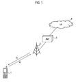
Fig. 1 shows an overall general configuration of a mobile communication system including a mobile communication terminal according to an embodiment of the invention. -
Fig. 2 is a functional block diagram showing a configuration of the mobile communication terminal according to the embodiment of the invention. -
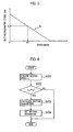
Fig. 3 describes a controlling method of setting parameters in the mobile communication terminal according to the embodiment of the invention. -
Fig. 4 shows a flow of operations of the mobile communication terminal according to the embodiment of the invention. -
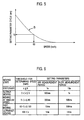
Fig. 5 describes a controlling method of setting parameters in a mobile communication terminal according to a first modified example of the invention. -
Fig. 6 describes a controlling method of setting parameters in a mobile communication terminal according to a second modified example. -
Fig. 7 shows a flow of operations of the mobile communication terminal according to the second modified example. - Embodiments of the present invention will be described in detail with reference to the drawings. Throughout the specification and drawings, identical or similar reference numerals refer to identical or similar parts. For the convenience of description, in the following embodiments, a CDMA mobile communication system is taken as an example of mobile communication systems of the present invention.
- (1) General Configuration of Mobile Communication System
Fig. 1 shows an overall general configuration of a mobile communication system including amobile communication terminal 1 according to this embodiment.
The mobile communication system shown inFig. 1 includes the mobile communication terminal I, a base station 2, a radio network controller 3 (hereafter, simply referred to as "RNC 3"), and a core network 4 ("CN 4").
When themobile communication terminal 1 is in the radio communication area of the base station 2, themobile communication terminal 1 establishes a radio communication link with the base station 2, and communicates to other communication apparatuses via the CN 4. Here, themobile communication terminal 1 performs the closed-loop transmission power control to control the reception power in the downlink (DL), that is, the transmission power of the base station 2.
The base station 2, under the radio-resource management by the RNC 3, communicates wirelessly to themobile communication terminal 1. Here, the base station 2 performs the closed-loop transmission power control to control the transmission power of themobile communication terminal 1 in the uplink (tJL).
The RNC 3 serves as a host system for the base station 2, and performs, among other things, the control of the radio resources to be used by the base station 2. A function of the RNC 3 is to control the transmission power control (outer-loop transmission power control) performed by themobile communication terminal 1, To this end, the RNC 3 controls the target BLER that is set in themobile communication terminal 1. In an alternative configuration, the function of the RNC 3 may be incorporated into and carried out by the base station 2.
The CN 4, which is a network to perform a position control, a call control, and a service control, includes an ATM switched network, a packet switched network, a router network, and the like. - (2) Configuration of Mobile Communication Terminal
A configuration of themobile communication terminal 1 according to this embodiment is described by referring toFig. 2 . Most of the descriptions will be given to the parts that are related to the present invention. - (2.1) General Configuration of Mobile Communication Terminal
Themobile communication terminal 1 includes anantenna 101, anRF section 102, adespreader 103, anRAKE receiver 104, ameasurement controller 105, atransmission power controller 106, atarget value updater 107, and atransmission signal generator 108.
When theantenna 101 receives a signal, the received signal is inputted to theRF section 102 and is downconverted. The received signal that has been downconverted is then subjected to a despreading processing in thedespreader 103. Used in the processing are a scrambling code, a channelization code and the like assigned by the base station 2.
In theRAKE receiver 104, the received signal that has been despread is subjected to RAKE combining as well as to error correction decoding. TheRAKE receiver 104 outputs data series that are then inputted to themeasurement controller 105, thetransmission power controller 106, and thetarget value updater 107.
In thetransmission power controller 106, the reception SIR (instantaneous reception quality) is measured on the data series outputted from theRAKE receiver 104. The measured reception SIR is then compared with the target SIR, and the comparison result is used to control the transmission power of the base station 2. In short, thetransmission power controller 106 performs the inner-loop control.
In thetarget value updater 1,07, the reception BLER (long-term reception quality) is measured on the data series outputted from theRAKE receiver 104. The measured reception BLER is then compared with the target BLER, and the comparison result is used to update the target SIR In short, thetarget value updater 107 performs the outer-loop control.
In themeasurement controller 105, the moving speed of themobile communication terminal 1 is acquired, and the acquired speed is used to control the length of the period for measuring each of the reception SIR and the reception BLER. Detailed description will be given later for thetransmission power controller 106, thetarget value updater 107, and themeasurement controller 105.
After the data series from theRAKE receiver 104 are subjected to a quadrature demodulation, a decoding processing, and an error correction decoding, the resultant data series are converted into audio signals and image signals. The resultant signals are then outputted.
In thetransmission signal generator 108, a transmission signal is generated and then is supplied to theRF section 102. In the RF section, the transmission signal is subjected to a modulation processing and to a spread spectrum processing. The signal thus processed is then upconverted, and then is transmitted to the base station 2 via theantenna 101. - (2.2) Configuration Details of Transmission Power Controller
Now, thetransmission power controller 106 is described in detail. Thetransmission power controller 106 includes a reception-SIR measurement unit 1061, anSIR comparator 1062, and acontrol command generator 1063.
To the reception-SIR measurement unit 1061, the signal power value and the interfering power value are inputted from theRAKE receiver 104. On the basis of these values, the reception SIR is measured. To obtain the reception SIR, the received signal code power (RSCP) and the interference signal code power (ISCP) have to be obtained. In an example, the RSCP is obtained as the sum of mean squares of the real part and of the imaginary part of pilot symbols while the ISCP is obtained as the variances of the real part and of the imaginary part from the respective mean values of the pilot symbols.
In theSIR comparator 1062, the reception SIR measured by the reception-SIR measurement unit 1061 is compared with the target SIR set by a target-SIR setting unit 1074, which is to be described later. Whether the value of the reception SIR is not less than the value of the target SIR is determined, and the determination result is notified to thecontrol command generator 1063.
Thecontrol command generator 1063 generates control commands in accordance with the results of the determination performed by theSIR comparator 1062. When the reception SIR is not as high as the target SIR, an "UP" command, which is a control command to increase the transmission power, is generated. In contrast, when the reception SIR is not less than the target SIR, a "DOWN" command, a control command to decrease the transmission power, is generated. The control commands generated by thecontrol command generator 1063 are supplied to thetransmission signal generator 108, and are multiplexed with the transmission signals. r - (2.3) Configuration Details of Target Value Update
Now, thetarget value updater 107 is described in detail. Thetarget value updater 107 includes a reception-BLER measurement unit 1071, a target-BLER storage 1073, and aBLER comparator 1072, and the target-SIR setting unit 1074.
In the reception-BLER measurement section 1071, a CRC error detection is performed on, for example, each of the transport blocks of the data series outputted from theRAKE receiver 104. The detection results are used to measure the reception BLER.
TheBLER comparator 1072 obtains a correction value for the target SIR. The correction value is made proportional to the difference between the reception BLER and the target BLER that is stored in the target-BLER storage 1073.
The target-SIR setting unit 1074, sets a target SIR to theSIR comparator 1062 in accordance with the correction value for the target SIR obtained by theBLER comparator 1062. - (2.4) Configuration Detail of Measurement Controller
Now, themeasurement controller 105 is described in detail. Themeasurement controller 105 includes a moving-speed acquiring unit 1051, an SIRmeasurement period controller 1052, and a BLERmeasurement period controller 1053.
The moving-speed acquiring unit 1051 is configured to acquire the moving speed of the terminal to which theunit 1051 belongs in any one of the following ways (a) to (c).- (a) A first way of obtaining the moving speed uses the Doppler frequency (fd) that is calculated from the fluctuation due to Rayleigh fading (fading pitch).
- (b) A second way of obtaining the moving speed uses the counts representing how many times the
mobile communication terminal 1 moves between cells. In this case, the moving speed may be measured not only by themobile communication terminal 1 but also by the base station 2. In the latter's case, the measured speed is notified to themobile communication terminal 1. - (c) A third way of obtaining the moving speed uses the GPS, an acceleration sensor, or the like.
measurement period controller 1052 controls the reception-SIR measurement period used in the reception-SIR measurement unit 1061. Here, the control is performed in accordance with the moving speed acquired by the moving-speed acquiring unit 1051. The SIRmeasurement period controller 1052 controls the cycle of generating control commands in thecontrol command generator 1063. Here, the control is performed also in accordance with the moving speed acquired by the moving-speed acquiring unit 1051.
The BLERmeasurement period controller 1053 controls the reception-BLER measurement period used in the reception-BLER measurement unit 1071. Here, the control is performed in accordance with the moving speed acquired by the moving-speed acquiring unit 1051. The BLERmeasurement period controller 1053 controls the cycle of updating the target SIR in the target-SIR setting unit 1074. Here, the control is performed also in accordance with the moving speed acquired by the moving-speed acquiring unit 1051.
In the following descriptions, a generic term "setting parameters" is used for the reception-SIR measurement period, the cycle of generating control commands, the reception-BLER measurement period, and the cycle of updating the target SIR - (3) Operations for Controlling Setting Parameters
Now, the operations of controlling the setting parameters performed by the SIRmeasurement period controller 1052 and the BLERmeasurement period controller 1053 are described in detail.
AsFig. 3 shows, the SIRmeasurement period controller 1052 linearly (using a liner function) calculates the setting parameters (the reception-SIR measurement period and the cycle of generating the control commands) in accordance with the moving speed acquired by the moving-speed acquiring unit 1051.
Likewise, the 13LERmeasurement period controller 1053 linearly calculates the setting parameters (the reception-BLER measurement period and the cycle of updating the target SIR) in accordance with the moving speed acquired by the moving-speed acquiring unit 1051.
Fig. 3 shows that an increase in the moving speed acquired by the moving-speed acquiring unit 1051 decreases the value of the cycle (period) of the setting parameters. Note that theFig. 3 shows the cycle of the setting parameters on the basis of the period of time, but the cycle may be based, for example, on the number of symbols or on the number of slots. - (4) Operations of Mobile Communication Terminal
Now, the operations of themobile communication terminal 1 are described with reference toFig. 4 .
Instep S 101, the moving-speed acquiring unit 1051 acquires the moving speed vt of themobile communication terminal 1,
Instep S 102, the moving-speed acquiring unit 1051 determines whether the newly acquired moving speed vt is equivalent to the moving speed vt-1 having been acquired on the previous occasion. When the newly acquired moving speed vt differs from the previously-acquired moving speed vt-1, the process in step S103 has to be performed next.
In step S103, the SIRmeasurement period controller 1052 and the BLERmeasurement period controller 1053 calculates, in accordance with the principle shown inFig. 3 , the setting parameters corresponding to the moving speed acquired in step 5101,
Instep S 104, the SIRmeasurement period controller 1052 sets the setting parameters (the SIR measurement period and the cycle of generating control commands) calculated in step S103 to the reception-SIR measurement unit 1061 and thecontrol command generator 1063. Meanwhile, the BLERmeasurement period controller 1053 sets the setting parameters (the BLER measurement period and the cycle of updating target SIR) calculated instep S 103 to the reception-BLER measurement unit 1071 and the target-SIR setting unit 1074.
Consequently, the reception-SIR measurement unit 1061 uses the SIR measurement period set by the SIRmeasurement period controller 1052, and thus the reception SIR is measured. Meanwhile, thecontrol command generator 1063 uses the cycle of generating control commands set by the SIRmeasurement period controller 1052, and thus the control command is generated.
In addition, the reception-BLER measurement unit 1071 uses the BLER measurement period set by the BLERmeasurement period controller 1053, and thus the reception BLER is measured. Meanwhile, the target-SIR setting unit 1074 uses the cycle of updating the target SIR set by the BLERmeasurement period controller 1053, and thus the target SIR is updated. - (5) Advantageous Effects
As has been described thus far, themobile communication terminal 1 in this embodiment controls the reception-BLER measurement period and the cycle of updating the target SIR in accordance with the moving speed of themobile communication terminal 1. Accordingly, the disconnection of the communications is made less likely to occur even in a rapidly changing wireless communication environment. - Specifically, when the
mobile communication terminal 1 moves fast, the reception-BLER measurement period is shortened. The reception BLER is thus measured with higher accuracy. In addition, when themobile communication terminal 1 moves fast, the cycle of updating the target SIR is shortened. The tracking performance to the wireless communication environment is thus improved. - The
mobile terminal 1 in this embodiment controls the reception-SIR measurement period and the cycle of generating control commands (transmission cycle) in accordance with the moving speed of themobile communication terminal 1. Accordingly, the disconnection of the communications is made further less likely to occur even in a rapidly changing wireless communication environment. - Specifically, when the
mobile communication terminal 1 moves fast, the reception-SIR measurement period is shortened. The reception SIR is thus measured with higher accuracy In addition, when themobile communication terminal 1 moves fast, the cycle of generating control commands (transmission cycle) is shortened. The tracking performance to the wireless communication environment is thus improved. - In addition, the setting parameters in this embodiment are changed only when the newly acquired moving speed differs from the previously-acquired one. To put it other way, the setting parameters are not changed when the newly acquired moving speed is equivalent to the previously-acquired one. Consequently, the load for processing on the
mobile communication terminal 1 and the increase in the power consumption can be reduced. - The setting parameters in the above-described embodiment are calculated linearly (using a linear function) in relation to the moving speed of the
mobile communication terminal 1. In this Modified Example, however, the setting parameters are, asFig. 5 shows, calculated non-linearly. - In this modified example, the setting parameters are calculated non-linearly, Accordingly, as the
mobile communication terminal 1 moves faster, the setting-parameter cycle is shortened sharply. For example, the setting-parameter cycle y2 at the speed of 60 km/h inFig. 5 has a value significantly smaller than the setting-parameter cycle y1 at the speed of 60 km/h inFig. 3 . - Consequently, non-linear calculation of the setting parameters can improve the measurement accuracy of the reception SIR and the reception BLER when the moving speed of the
mobile communication terminal 1 increases. In addition, the tracking performance to the wireless communication environment is thus improved. - In the configuration described in this modified example, the setting parameters are not calculated from the moving speed of the
mobile communication terminal 1. Instead, setting parameters corresponding to the moving speed are acquired from a table that has been provided in advance. -
Fig. 6 is a configuration example of a table that makes the moving speed and the setting parameters correspond to each other. The table shown inFig. 6 includes such items as "moving state," "threshold for determining speed," and "setting parameters." - Five steps of moving state-stationary, slowly-moving, moving at medium speed, fast-moving, and ultrafast-moving--are defined. Thresholds for determining speed are defined to classify these steps of moving state. Different values for each of the setting parameters (SIR measurement period and BLER measurement period in this example) are defined in accordance with the steps of moving state.
-
Fig. 7 is a flowchart illustrating the flow of operations of themobile communication terminal 1 according to this modified example. In the flowchart shown inFig. 7 , the setting parameters are acquired from the table in step S203 so as to correspond to the moving speed vt that has been obtained in step S201. In this respect, the operations shown in the flowchart ofFig. 7 differs from the operations shown in the flowchart ofFig. 4 . - In the configuration of this modified example, the setting parameters are not calculated from the moving speed of the
mobile communication terminal 1, Instead, setting parameters corresponding to the moving speed are acquired from the table that has been provided in advance. Consequently, the load for processing on themobile communication terminal 1 can be reduced in this modified example from the load in the case of the above-described embodiment. - The present invention has been described thus far using an embodiment and its modified examples. It should be understood that the present invention is not limited by the descriptions or the drawings, though these descriptions and drawings form parts of the disclosure. Those skilled in the art can easily understand that various alternative embodiments, examples, and applications are conceivable.
- In the above-described embodiment, the moving-
speed acquiring unit 1051 is configured to acquire the moving speed as the moving state of themobile communication terminal 1, but what is to be acquired in the present invention is not limited to the moving speed. Alternatively, the moving-speed acquiring unit 1051 may be configured to acquire information indicating the state of themobile communication terminal 1, that is, information on whether the mobile communication terminal is in a stationary state or is moving. In this case, the load for processing on themobile communication terminal 1 can be reduced significantly. - In addition, the long-term reception quality measured in the above-described embodiment is the reception BLER, but the quality to be measured for this purpose in the present invention is not limited to the reception BLER. In an alternative configuration, the reception bit error rate (reception BER) is to be measured.
- Moreover, the mobile communication system of the above-described embodiment is a system of a CDMA, but the system of the present invention is not limited to a CDMA system. The above-described transmission power controlling method is applicable to a mobile communication system of a different type.
- It should be understood that the present invention includes various embodiments that are not described in this specification. Rather, the present invention is defined only by the claims relevant to this disclosure.
Claims (7)
- A mobile communication terminal comprising:a transmission power controller configured to measure a first reception quality of a signal received from a base station, and to control a transmission power of the base station in accordance with a result of comparison between the first reception quality and a target value of the first reception quality;a target value updater configured to measure a second reception quality of the received signal, and to update the target value in accordance with a measurement result of the second reception quality; anda measurement controller configured to acquire a moving state of the mobile communication terminal, and, based on the acquired moving state, to control a period of measuring the second reception quality and a cycle of updating the target value.
- The mobile communication terminal according to claim 1, wherein
the first reception quality is a reception quality used in an inner-loop control, and
the second reception quality is a reception quality used in an outer-loop control. - The mobile communication terminal according to claim 1, wherein
the first reception quality is an instantaneous reception quality, and
the second reception quality is a long-term reception quality that is a reception quality measured over a longer period of time than a period of time over which the instantaneous reception quality is measured. - The mobile communication terminal according to claim 1, wherein the measurement controller is configured to acquire, as the moving state, a moving speed of the mobile communication terminal.
- The mobile communication terminal according to claim 1 wherein
the transmission power controller is configured to transmit, to the base station, a control command to control the transmission power of the base station, and
the measurement controller is configured further to control a period of measuring the first reception quality and a cycle of transmitting the control command. - The mobile communication terminal according to claim 1, wherein the measurement controller is configured to change the period of measuring and the cycle of updating only on condition that a moving state acquired newly on this occasion differs from a moving state having been acquired on the previous occasion.
- A transmission power controlling method comprising the steps of:measuring a first reception quality of a signal received from a base station;controlling a transmission power of the base station in accordance with a result of comparison between the first reception quality and a target value of the first reception quality;measuring a second reception quality of the received signal;updating the target value in accordance with a measurement result of the second reception quality;acquiring a moving state of a mobile communication terminal; andcontrolling a period of measuring the second reception quality and a cycle of updating the target value, based on the acquired moving state.
Applications Claiming Priority (1)
| Application Number | Priority Date | Filing Date | Title |
|---|---|---|---|
| JP2006340504A JP4326561B2 (en) | 2006-12-18 | 2006-12-18 | Mobile communication terminal and transmission power control method |
Publications (2)
| Publication Number | Publication Date |
|---|---|
| EP1936830A1 true EP1936830A1 (en) | 2008-06-25 |
| EP1936830B1 EP1936830B1 (en) | 2010-11-24 |
Family
ID=39148218
Family Applications (1)
| Application Number | Title | Priority Date | Filing Date |
|---|---|---|---|
| EP20070024496 Not-in-force EP1936830B1 (en) | 2006-12-18 | 2007-12-18 | Mobile communication terminal and transmission power controlling method |
Country Status (6)
| Country | Link |
|---|---|
| US (1) | US8000733B2 (en) |
| EP (1) | EP1936830B1 (en) |
| JP (1) | JP4326561B2 (en) |
| KR (1) | KR100953583B1 (en) |
| CN (1) | CN101207421B (en) |
| DE (1) | DE602007010717D1 (en) |
Families Citing this family (11)
| Publication number | Priority date | Publication date | Assignee | Title |
|---|---|---|---|---|
| JP5075019B2 (en) * | 2008-06-04 | 2012-11-14 | 株式会社エヌ・ティ・ティ・ドコモ | Mobile communication terminal apparatus and transmission power setting method |
| EP2290676A4 (en) | 2008-06-12 | 2012-01-11 | Mitsubishi Materials Corp | METHOD FOR JOINING SUBSTRATE AND OBJECT TO BE MOUNTED USING SOLDER PULP |
| US8983397B2 (en) * | 2008-10-10 | 2015-03-17 | Qualcomm Incorporated | Method and apparatus for channel feedback by multiple description coding in a wireless communication system |
| JP5108865B2 (en) * | 2009-11-30 | 2012-12-26 | 株式会社エヌ・ティ・ティ・ドコモ | Mobile communication terminal, network device, mobile communication system, and mobile communication method |
| EP2509371A4 (en) * | 2009-12-02 | 2014-09-17 | Fujitsu Ltd | BASE STATION APPARATUS, MOBILE COMMUNICATION SYSTEM, AND METHOD FOR DETERMINING RADIO SIGNAL QUALITY |
| CN102291765B (en) * | 2010-06-21 | 2016-03-30 | 中兴通讯股份有限公司 | A kind of outer-loop power controlling method and device |
| KR101777874B1 (en) * | 2011-04-12 | 2017-09-12 | 삼성전자주식회사 | Wireless terminal and method for providing alternative frequency in wireless terminal |
| WO2011144112A2 (en) * | 2011-05-27 | 2011-11-24 | 华为技术有限公司 | Speech signal processing method and device, and access network system |
| JP6026415B2 (en) | 2011-08-05 | 2016-11-16 | パナソニック インテレクチュアル プロパティ コーポレーション オブ アメリカPanasonic Intellectual Property Corporation of America | Terminal, transmission apparatus, reception quality report method, and reception method |
| JP6424515B2 (en) * | 2014-08-26 | 2018-11-21 | 沖電気工業株式会社 | Wireless communication system, transmission power control method and wireless communication apparatus |
| JP2019013053A (en) * | 2018-10-25 | 2019-01-24 | 沖電気工業株式会社 | Radio communication system, transmission power control method, and radio communication device |
Citations (3)
| Publication number | Priority date | Publication date | Assignee | Title |
|---|---|---|---|---|
| WO1997034372A1 (en) * | 1996-03-15 | 1997-09-18 | Motorola Inc. | Method and apparatus for power control in a communication system |
| EP1635483A1 (en) * | 2003-06-19 | 2006-03-15 | Fujitsu Limited | Transmission power controlling method and apparatus |
| WO2006121089A1 (en) * | 2005-05-10 | 2006-11-16 | Ntt Docomo, Inc. | Transmission power control method and apparatus |
Family Cites Families (18)
| Publication number | Priority date | Publication date | Assignee | Title |
|---|---|---|---|---|
| JP2995065B2 (en) | 1989-07-03 | 1999-12-27 | 日本電信電話株式会社 | Transmission power control method in mobile communication system |
| FI103555B1 (en) * | 1996-06-17 | 1999-07-15 | Nokia Mobile Phones Ltd | Checking the transmit power in wireless packet data transmission |
| CN1102308C (en) * | 1996-06-27 | 2003-02-26 | Ntt移动通信网株式会社 | transmit power controller |
| JP3397677B2 (en) * | 1998-02-10 | 2003-04-21 | 松下電器産業株式会社 | Transmission power control device and wireless communication device |
| JP3358565B2 (en) * | 1998-11-02 | 2002-12-24 | 日本電気株式会社 | Transmission power control method, transmission power control device, mobile station, base station, and control station |
| JP3346332B2 (en) * | 1999-04-16 | 2002-11-18 | 日本電気株式会社 | Code division multiple access mobile communication system |
| GB2355366B (en) * | 1999-10-11 | 2003-08-20 | Ericsson Telefon Ab L M | Radio transceiver |
| JP2003198443A (en) * | 2001-12-26 | 2003-07-11 | Matsushita Electric Ind Co Ltd | Base station device, communication terminal device, and wireless communication method |
| JP2003318818A (en) | 2002-04-23 | 2003-11-07 | Nec Corp | Cellular telephone system and transmission power control method therefor |
| US7075905B2 (en) * | 2002-09-11 | 2006-07-11 | Qualcomm Incorporated | Quality indicator bit (QIB) generation in wireless communications systems |
| US7162262B2 (en) * | 2002-09-23 | 2007-01-09 | Telefonaktiebolaget Lm Ericsson (Publ) | Methods, systems and computer program products for requesting received power levels based on received block error rates utilizing an anti-windup and/or emergency procedure |
| US7440769B2 (en) * | 2003-01-31 | 2008-10-21 | Nec Corporation | Target value control method for transmission power control, base station control device and mobile station used for the same |
| JP4230288B2 (en) | 2003-06-13 | 2009-02-25 | 富士通株式会社 | Transmission power control method and mobile station |
| JP2005167710A (en) | 2003-12-03 | 2005-06-23 | Matsushita Electric Ind Co Ltd | Power measuring apparatus and measuring method |
| JP2006157467A (en) * | 2004-11-30 | 2006-06-15 | Nec Corp | Radio communication apparatus, its transmission power control method and program |
| JP4577501B2 (en) * | 2005-03-03 | 2010-11-10 | 日本電気株式会社 | Transmission power control method |
| JP4651446B2 (en) | 2005-04-27 | 2011-03-16 | 株式会社エヌ・ティ・ティ・ドコモ | Communication control device and communication control method |
| JP4789705B2 (en) | 2006-06-08 | 2011-10-12 | 富士通株式会社 | Transmission power control method, outer loop control method, and mobile station |
-
2006
- 2006-12-18 JP JP2006340504A patent/JP4326561B2/en not_active Expired - Fee Related
-
2007
- 2007-12-18 KR KR20070133125A patent/KR100953583B1/en not_active Expired - Fee Related
- 2007-12-18 EP EP20070024496 patent/EP1936830B1/en not_active Not-in-force
- 2007-12-18 CN CN2007101996005A patent/CN101207421B/en not_active Expired - Fee Related
- 2007-12-18 DE DE200760010717 patent/DE602007010717D1/en active Active
- 2007-12-18 US US11/959,066 patent/US8000733B2/en not_active Expired - Fee Related
Patent Citations (4)
| Publication number | Priority date | Publication date | Assignee | Title |
|---|---|---|---|---|
| WO1997034372A1 (en) * | 1996-03-15 | 1997-09-18 | Motorola Inc. | Method and apparatus for power control in a communication system |
| EP1635483A1 (en) * | 2003-06-19 | 2006-03-15 | Fujitsu Limited | Transmission power controlling method and apparatus |
| WO2006121089A1 (en) * | 2005-05-10 | 2006-11-16 | Ntt Docomo, Inc. | Transmission power control method and apparatus |
| EP1895682A1 (en) * | 2005-05-10 | 2008-03-05 | NTT DoCoMo INC. | Transmission power control method and apparatus |
Also Published As
| Publication number | Publication date |
|---|---|
| US20080146162A1 (en) | 2008-06-19 |
| CN101207421A (en) | 2008-06-25 |
| JP4326561B2 (en) | 2009-09-09 |
| KR20080056677A (en) | 2008-06-23 |
| CN101207421B (en) | 2013-04-24 |
| JP2008154003A (en) | 2008-07-03 |
| KR100953583B1 (en) | 2010-04-21 |
| DE602007010717D1 (en) | 2011-01-05 |
| EP1936830B1 (en) | 2010-11-24 |
| US8000733B2 (en) | 2011-08-16 |
Similar Documents
| Publication | Publication Date | Title |
|---|---|---|
| EP1936830B1 (en) | Mobile communication terminal and transmission power controlling method | |
| US6862458B2 (en) | Transmission power control apparatus and transmission power control method | |
| JP3397677B2 (en) | Transmission power control device and wireless communication device | |
| US7366538B2 (en) | Mobile communication system and communication method for mobile communication system | |
| CN100466837C (en) | Method and apparatus for generating a quality measure target value based on channel conditions | |
| US20080108315A1 (en) | Method and arrangement for controlling transmission power and a network element | |
| KR100940901B1 (en) | Transmission power control method and device | |
| JP2007520908A (en) | Wireless communication system | |
| JP5083328B2 (en) | Transmission power control method and apparatus | |
| WO2011119080A1 (en) | Reducing load in a communications network | |
| KR20010062006A (en) | Cdma transmission power control in variable control cycle | |
| EP0924875B1 (en) | Diversity reception method and apparatus in a CDMA system | |
| KR20070104901A (en) | Interference estimation in the presence of frequency errors | |
| US7009955B2 (en) | Method for outer loop power control to comply with quality requirements of all transport channels within a coded composite transport channel | |
| US6625465B1 (en) | Backward closed loop power control apparatus for mobile communication system and method using the same | |
| EP1156687A1 (en) | Base station device and transmission power control method |
Legal Events
| Date | Code | Title | Description |
|---|---|---|---|
| PUAI | Public reference made under article 153(3) epc to a published international application that has entered the european phase |
Free format text: ORIGINAL CODE: 0009012 |
|
| 17P | Request for examination filed |
Effective date: 20071218 |
|
| AK | Designated contracting states |
Kind code of ref document: A1 Designated state(s): AT BE BG CH CY CZ DE DK EE ES FI FR GB GR HU IE IS IT LI LT LU LV MC MT NL PL PT RO SE SI SK TR |
|
| AX | Request for extension of the european patent |
Extension state: AL BA HR MK RS |
|
| AKX | Designation fees paid |
Designated state(s): DE FI FR GB SE |
|
| GRAP | Despatch of communication of intention to grant a patent |
Free format text: ORIGINAL CODE: EPIDOSNIGR1 |
|
| RIC1 | Information provided on ipc code assigned before grant |
Ipc: H04W 52/04 20090101AFI20100525BHEP |
|
| GRAS | Grant fee paid |
Free format text: ORIGINAL CODE: EPIDOSNIGR3 |
|
| GRAA | (expected) grant |
Free format text: ORIGINAL CODE: 0009210 |
|
| AK | Designated contracting states |
Kind code of ref document: B1 Designated state(s): DE FI FR GB SE |
|
| REG | Reference to a national code |
Ref country code: GB Ref legal event code: FG4D |
|
| RAP2 | Party data changed (patent owner data changed or rights of a patent transferred) |
Owner name: NTT DOCOMO, INC. |
|
| REF | Corresponds to: |
Ref document number: 602007010717 Country of ref document: DE Date of ref document: 20110105 Kind code of ref document: P |
|
| REG | Reference to a national code |
Ref country code: SE Ref legal event code: TRGR |
|
| PLBE | No opposition filed within time limit |
Free format text: ORIGINAL CODE: 0009261 |
|
| STAA | Information on the status of an ep patent application or granted ep patent |
Free format text: STATUS: NO OPPOSITION FILED WITHIN TIME LIMIT |
|
| 26N | No opposition filed |
Effective date: 20110825 |
|
| REG | Reference to a national code |
Ref country code: DE Ref legal event code: R097 Ref document number: 602007010717 Country of ref document: DE Effective date: 20110825 |
|
| PGFP | Annual fee paid to national office [announced via postgrant information from national office to epo] |
Ref country code: DE Payment date: 20141209 Year of fee payment: 8 Ref country code: SE Payment date: 20141211 Year of fee payment: 8 Ref country code: FI Payment date: 20141209 Year of fee payment: 8 Ref country code: GB Payment date: 20141217 Year of fee payment: 8 |
|
| PGFP | Annual fee paid to national office [announced via postgrant information from national office to epo] |
Ref country code: FR Payment date: 20141208 Year of fee payment: 8 |
|
| REG | Reference to a national code |
Ref country code: DE Ref legal event code: R119 Ref document number: 602007010717 Country of ref document: DE |
|
| REG | Reference to a national code |
Ref country code: SE Ref legal event code: EUG |
|
| GBPC | Gb: european patent ceased through non-payment of renewal fee |
Effective date: 20151218 |
|
| PG25 | Lapsed in a contracting state [announced via postgrant information from national office to epo] |
Ref country code: SE Free format text: LAPSE BECAUSE OF NON-PAYMENT OF DUE FEES Effective date: 20151219 |
|
| REG | Reference to a national code |
Ref country code: FR Ref legal event code: ST Effective date: 20160831 |
|
| PG25 | Lapsed in a contracting state [announced via postgrant information from national office to epo] |
Ref country code: DE Free format text: LAPSE BECAUSE OF NON-PAYMENT OF DUE FEES Effective date: 20160701 Ref country code: GB Free format text: LAPSE BECAUSE OF NON-PAYMENT OF DUE FEES Effective date: 20151218 |
|
| PG25 | Lapsed in a contracting state [announced via postgrant information from national office to epo] |
Ref country code: FR Free format text: LAPSE BECAUSE OF NON-PAYMENT OF DUE FEES Effective date: 20151231 |
|
| PG25 | Lapsed in a contracting state [announced via postgrant information from national office to epo] |
Ref country code: FI Free format text: LAPSE BECAUSE OF NON-PAYMENT OF DUE FEES Effective date: 20151218 |