EP1936826A1 - Noise management circuit for a remote terminal of a telecommunication system - Google Patents
Noise management circuit for a remote terminal of a telecommunication system Download PDFInfo
- Publication number
- EP1936826A1 EP1936826A1 EP06292015A EP06292015A EP1936826A1 EP 1936826 A1 EP1936826 A1 EP 1936826A1 EP 06292015 A EP06292015 A EP 06292015A EP 06292015 A EP06292015 A EP 06292015A EP 1936826 A1 EP1936826 A1 EP 1936826A1
- Authority
- EP
- European Patent Office
- Prior art keywords
- frequency
- signals
- remote terminal
- noise
- management circuit
- Prior art date
- Legal status (The legal status is an assumption and is not a legal conclusion. Google has not performed a legal analysis and makes no representation as to the accuracy of the status listed.)
- Granted
Links
- 238000001228 spectrum Methods 0.000 claims abstract description 29
- 239000011230 binding agent Substances 0.000 claims abstract description 25
- 230000003595 spectral effect Effects 0.000 claims abstract description 17
- 238000001514 detection method Methods 0.000 claims description 5
- 230000001419 dependent effect Effects 0.000 claims description 3
- 238000007493 shaping process Methods 0.000 description 8
- 238000002347 injection Methods 0.000 description 5
- 239000007924 injection Substances 0.000 description 5
- 230000002238 attenuated effect Effects 0.000 description 3
- 230000007423 decrease Effects 0.000 description 3
- 238000010586 diagram Methods 0.000 description 3
- 101150012579 ADSL gene Proteins 0.000 description 2
- 102100020775 Adenylosuccinate lyase Human genes 0.000 description 2
- 108700040193 Adenylosuccinate lyases Proteins 0.000 description 2
- 230000008878 coupling Effects 0.000 description 2
- 238000010168 coupling process Methods 0.000 description 2
- 238000005859 coupling reaction Methods 0.000 description 2
- 239000000835 fiber Substances 0.000 description 2
- 238000000034 method Methods 0.000 description 2
- 239000000969 carrier Substances 0.000 description 1
- 230000015556 catabolic process Effects 0.000 description 1
- 238000006731 degradation reaction Methods 0.000 description 1
- 230000007246 mechanism Effects 0.000 description 1
Images

Classifications
-
- H—ELECTRICITY
- H04—ELECTRIC COMMUNICATION TECHNIQUE
- H04B—TRANSMISSION
- H04B3/00—Line transmission systems
- H04B3/02—Details
- H04B3/46—Monitoring; Testing
-
- H—ELECTRICITY
- H04—ELECTRIC COMMUNICATION TECHNIQUE
- H04L—TRANSMISSION OF DIGITAL INFORMATION, e.g. TELEGRAPHIC COMMUNICATION
- H04L5/00—Arrangements affording multiple use of the transmission path
- H04L5/003—Arrangements for allocating sub-channels of the transmission path
- H04L5/0044—Allocation of payload; Allocation of data channels, e.g. PDSCH or PUSCH
-
- H—ELECTRICITY
- H04—ELECTRIC COMMUNICATION TECHNIQUE
- H04L—TRANSMISSION OF DIGITAL INFORMATION, e.g. TELEGRAPHIC COMMUNICATION
- H04L5/00—Arrangements affording multiple use of the transmission path
- H04L5/003—Arrangements for allocating sub-channels of the transmission path
- H04L5/0058—Allocation criteria
- H04L5/006—Quality of the received signal, e.g. BER, SNR, water filling
-
- H—ELECTRICITY
- H04—ELECTRIC COMMUNICATION TECHNIQUE
- H04L—TRANSMISSION OF DIGITAL INFORMATION, e.g. TELEGRAPHIC COMMUNICATION
- H04L5/00—Arrangements affording multiple use of the transmission path
- H04L5/0001—Arrangements for dividing the transmission path
- H04L5/0003—Two-dimensional division
- H04L5/0005—Time-frequency
- H04L5/0007—Time-frequency the frequencies being orthogonal, e.g. OFDM(A) or DMT
Definitions
- Such a noise management circuit is already known in the art, e.g. in a domain of Digital Subscriber Lines DSL more particularly relating to spectral compatibility in mixed Central Office - Remote Terminal or CO - RT deployment.
- the first and second wires of the second cable binder are coupled with each other.
- the twisted pair links are shortened by bringing fiber deeper into the network and by introducing small Digital Subscriber Line Access Multiplexer's DSLAM closer to the end-customers.
- Such a Remote Terminal RT equipment is generally located in small boxes in the street, serving 50 to 100 end-customers.
- a DSLAM located at the operator buildings next to Plain Old Telephone Service POTS equipment is a Central Office CO.
- Downstream PSD Shaping a technique called "Downstream PSD Shaping" applied at the RT has been elaborated upon, and the tools for it have been adopted in the VDSL2 standards.
- the shape of the injected RT signal is similar to that of the CO signal attenuated over the CO-RT distance.
- a split frequency ST hereafter also referenced to as f1
- f1 the split frequency
- protected CO frequencies Below the split frequency f1 are the so-called protected CO frequencies.
- the RT is not allowed to disturb those protected frequencies more than a CO line would do.
- unprotected CO frequencies Above the split frequency f1 are the unprotected CO frequencies, which can be used by the RT to transmit at the maximum allowed PSD. DMT (Discrete Multi Tone) tones above this frequency will contribute most to the performance of the RT lines.
- DMT Discrete Multi Tone
- the main problem is thus to know the split frequency f1.
- a too pessimistic PSD Shaping calculation i.e. the RT signals too much suppressed, or split frequency f1 estimated too high
- said noise management circuit further comprises a noise generator adapted to inject a controllable frequency-dependent level of artificial noise into said first signals when passing via said remote terminal.
- the term 'coupled' should not be interpreted as being restricted to direct connections only.
- the scope of the expression 'a device A coupled to a device B' should not be limited to devices or systems wherein an output of device A is directly connected to an input of device B. It means that there exists a path between an output of A and an input of B which may be a path including other devices or means.
- each line shown in a cable binder represents a twisted pair of wires and that some wires, e.g. NU, of cable binders may not be used.
- the Power Spectral Density shaper PSDS arranges the frequency spectrum of signals transmitted from the remote terminal RT to the second end-customers RTEU into a shape that is similar to the shape of the frequency spectrum of the signals received at RT from the central office CO and intended to the first end-customers COEU, within the same frequency range.
- the frequency spectrum of second data carrying signals transmitted from the remote terminal RT to the second end-consumers RTEU which are formerly transmitted at the maximum allowed PSD mask has its lower frequency part transformed by the Power Spectral Density shaper PSDS into a modified shape with a transmit PSD that decreases with frequency for the same frequency range as the first signals transmitted from the central office CO to the first end-consumers COEU.
- the frequency spectrum of the second signals transmitted from the remote terminal RT to the second end-consumers RTEU keeps its former maximum allowed PSD mask.
- the final shape of the frequency spectrum of the second signals transmitted from the remote terminal RT to the second end-consumers RTEU is shown on the PSD versus frequency diagram C at the Figs. 1 and 2 .
- the power spectral density shaper PSDS arranges the frequency spectrum of signals transmitted from the remote terminal RT to the second end-customers RTEU into modified shape of which the transmit PSD decreases with the frequency within a first frequency range going up to a split-frequency f1, and which keeps a substantially high PSD level for higher frequencies.
- the split-frequency f1a between the shaped part the maximum PSD level, corresponds substantially to the highest frequency of the signals passing via the remote terminal RT from the central office CO.
- the noise generator NIS injects, at the location of the remote terminal RT, an artificial noise in the signals passing by from the central office CO.
- This artificial noise is injected within a frequency range of which the lowest frequency substantially corresponds to the chosen split frequency f1b and of which the highest frequency corresponds to the highest frequency of the signals from the remote RT to the second end-consumers RTEU.
- the frequency spectrum of this artificial noise has a shape that is similar to the shape of the frequency range of the signals from the remote RT to the second end-consumers RTEU within the same higher frequency range.
- the shape of this noise is calculated as such that the artificial split frequency f1b is forced upon the CO-RT mixed system, which could be set network-wide or per RT node.
- the chosen split frequency f1b can be lower than the given split frequency f1a from the prior art.
- the noise injected into the CO line has a start frequency equal to the desired split frequency, and will mislead the downstream receiver of the CO line. As such, those frequencies will not be used by the CO lines, and the RT lines can send full power over those.
- the split frequency f1 defines the so-called “protected” and “unprotected” frequency bands and because the injected noise has same spectrum as the RT injected signals, it makes it impossible for the CO lines to use those higher frequencies to transport data.
- the strong RT signals will couple through crosstalk into the CO signals in the second cable binder CBO and thereby blow away the weak CO signal, mainly at high frequencies. Owing to the noise injection, the CO line will no longer loose performance and risk instability.
- the CO-ADSL signal will not be able to sustain all of its 255 carriers as soon as the CO-RT attenuation exceeds a certain threshold.
- This threshold is dependent on cable type, cable diameter, and physical distance between CO and RT.
- the desired split frequency f1b can be calculated network wide (e.g. on tone 120) as such that all end-customers, whether connected at a CO line (COEU) or at a RT line (RTEU), can get a similar amount of minimum bitrate, without risk on instabilities.
- the level of injected noise can be calculated based on similar parameters used for RT PSD Shaping, e.g. based on cable characteristics and distance between CO and RT.
- RT PSD Shaping e.g. based on cable characteristics and distance between CO and RT.
- a simple shape, as the rectangular one mentioned above, or a complex one following the CO signal level could be used.
Landscapes
- Engineering & Computer Science (AREA)
- Signal Processing (AREA)
- Computer Networks & Wireless Communication (AREA)
- Quality & Reliability (AREA)
- Cable Transmission Systems, Equalization Of Radio And Reduction Of Echo (AREA)
Abstract
Description
- The present invention relates to a noise management circuit for a Remote Terminal of a telecommunication system comprising a Central Office and a plurality of End-Customers, said central office being coupled to first end-customers of said plurality for transmitting first signals to said first end-customers via wires of a first cable binder, via said remote terminal and via first wires of a second cable binder, said remote terminal being further coupled to second end-customers of said plurality for transmitting second signals to said second end-customers via second wires of said second cable binder, and said noise management circuit comprising a Power Spectral Density Shaper adapted to arrange the frequency spectrum of said second signals within a frequency range overlapping the frequency range of said first signals.
- Such a noise management circuit is already known in the art, e.g. in a domain of Digital Subscriber Lines DSL more particularly relating to spectral compatibility in mixed Central Office - Remote Terminal or CO - RT deployment. Therein, the first and second wires of the second cable binder are coupled with each other. In order to increase the downstream bitrate of DSL links, the twisted pair links are shortened by bringing fiber deeper into the network and by introducing small Digital Subscriber Line Access Multiplexer's DSLAM closer to the end-customers. Such a Remote Terminal RT equipment is generally located in small boxes in the street, serving 50 to 100 end-customers. A DSLAM located at the operator buildings next to Plain Old Telephone Service POTS equipment is a Central Office CO.
- Problems arise when the RT and CO inject downstream DSL signals on their respective lines in the same cable binder towards the end-customers or users, transmit signals which are using overlapping frequency bands with similar transmit power or transmit Power Spectral Density PSD levels. Indeed, due to the crosstalk between twisted pairs in the cable binder between the RT and the houses (users), the relatively strong RT injected downstream signals will cause strong crosstalk noise into the CO injected downstream signals that are attenuated due to their transfer from CO to RT through the cable binder. Especially the highest frequencies of the CO line will be affected (the higher the frequency, the higher the crosstalk coupling). A consequence is that the CO lines via the cable binder are loosing bitrate, and risk on instabilities when the crosstalk from the RT lines is not stable (e.g. when switching on/off those DSL lines).
- In last years, a technique called "Downstream PSD Shaping" applied at the RT has been elaborated upon, and the tools for it have been adopted in the VDSL2 standards.
- PSD Shaping from RT is a technique where the PSD (Power Spectral Density) of the RT injected signal is shaped as such that it, after being cross-talked to CO lines, will not harm the CO lines more than as if it would have been a CO line.
- Key principle in PSD Shaping is that the CO lines must be "protected", in a sense that they should not experience bitrate loss or an increased instability risk.
- In other words, for the same frequency range, the shape of the injected RT signal is similar to that of the CO signal attenuated over the CO-RT distance. However, there exists a "split frequency ST" (hereafter also referenced to as f1) that is the start of the upper frequencies that can not be used anymore by the CO lines due to too high loop attenuation. Below the split frequency f1 are the so-called protected CO frequencies. The RT is not allowed to disturb those protected frequencies more than a CO line would do. Above the split frequency f1 are the unprotected CO frequencies, which can be used by the RT to transmit at the maximum allowed PSD. DMT (Discrete Multi Tone) tones above this frequency will contribute most to the performance of the RT lines.
- The main problem is thus to know the split frequency f1.
- The basic principle of RT - PSD Shaping today is that:
- no configuration changes of CO lines PSD may be requested when introducing a RT; this is because the CO lines are not always under the supervision of the owner of the RT due to local loop unbundling and
- (almost) no impact of CO lines performance is allowed when introducing a RT.
- A consequence is that the ST frequency needs to be located high enough in the frequency range, on cost of the performance of RT lines. The CO lines dominate the deployment rules, and the lines connected to the RT need to adapt to it.
- When the PSD Shaping would be calculated too optimistically (i.e. the RT signals are not enough suppressed, or split frequency f1 is estimated too low), then a consequence will be bitrate impact on the CO lines together with an increased risk on instabilities of the CO lines.
- A too pessimistic PSD Shaping calculation (i.e. the RT signals too much suppressed, or split frequency f1 estimated too high) will cause a lower than needed bitrate at the RT lines, and an increased risk on instabilities of the RT lines.
- An object of the present invention is to provide a noise management circuit of the above known type but adapted to overcome the above-mentioned problems.
- According to the invention, this object is achieved due to the fact that said noise management circuit further comprises a noise generator adapted to inject a controllable frequency-dependent level of artificial noise into said first signals when passing via said remote terminal.
- The idea of the invention is to fix the split frequency f1 at a predetermined value by setting the start frequency of the noise injection circuit accordingly.
- While maintaining the rule that no configuration changes can be done on CO lines in order to start RT deployment, it is proposed to enforce in a controlled way a split frequency f1, without increasing the instability risk of CO lines. This is done by injecting artificially noise at the RT location into the CO lines passing that location and in the same binder. This noise injection will make sure that the CO·lines will not load any bits above f1 and as such an artificial split frequency f1 can be enforced, redefining the protected and unprotected frequency bands. This injected noise indeed has at least the same spectrum as the RT injected signals, and makes it impossible for the CO lines to use the frequencies above f1 to transport data.
- It is to be noted that the split frequency can be chosen network wide or per RT node.
- It is also to be noted that the
European Patent Application EP-1641173-A1 (ApplicationNo 04292292.2 - Another characterizing embodiment of the present invention is that said power spectral density shaper is adapted to arrange the frequency spectrum of said second signals into a shape that is similar to that of the frequency spectrum of said first signals when passing via said remote terminal within a first frequency range going up to a split-frequency corresponding substantially to the highest frequency of said first signals, and that said noise generator is adapted to inject said artificial noise into said first signals when passing via said remote terminal for a second frequency range of which the lowest frequency substantially corresponds to said split frequency.
- In this way, compared to known RT PSD Shaping, there is no longer a risk on creating instabilities at CO lines (when being overoptimistic) or loose in performance at RT lines (when being too pessimistic). This is achieved because the injected noise is a stable (always present) noise that hides all on-off switching of RT connected lines.
- In a preferred embodiment, the present invention is further characterized in that said noise management circuit further comprises a frequency detection circuit adapted to define said split frequency.
- Further characterizing embodiments of the present noise management circuit are mentioned in the appended claims.
- It is to be noticed that the term 'comprising', used in the claims, should not be interpreted as being restricted to the means listed thereafter. Thus, the scope of the expression 'a device comprising means A and B' should not be limited to devices consisting only of components A and B. It means that with respect to the present invention, the only relevant components of the device are A and B.
- Similarly, it is to be noticed that the term 'coupled', also used in the claims, should not be interpreted as being restricted to direct connections only. Thus, the scope of the expression 'a device A coupled to a device B' should not be limited to devices or systems wherein an output of device A is directly connected to an input of device B. It means that there exists a path between an output of A and an input of B which may be a path including other devices or means.
- The above and other objects and features of the invention will become more apparent and the invention itself will be best understood by referring to the following description of an embodiment taken in conjunction with the accompanying drawings wherein:
-
Fig. 1 represents a telecommunication system including a Remote Terminal (RT) with a Power Spectral Density shaper (PSDS) as known from the prior art; and -
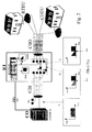
Fig. 2 represents a Remote Terminal with a noise management circuit (NIS) according to the invention. - The telecommunication system shown at
Fig. 1 is a classical system as known from prior art and comprises a Remote Terminal RT having DSL modems RTDSLM coupled to a Central Office CO via a fiber feeding FF and coupled to a plurality of End-Customers or End-Users RTEU via wires of a cable binder CBO. The central office CO, or more particularly at least one DSL modem CODSLM thereof, is coupled to another plurality of end-customers COEU via the cascade coupling of wires of another cable binder CBI, a distribution frame located in the remote terminal RT and other wires of the cable binder CBO. A distribution frame of the remote terminal RT interconnects the wires of the cable binder CBI with the other wires of the cable binder CBO. - It is to be noted that in the
Figs. 1 and2 each line shown in a cable binder represents a twisted pair of wires and that some wires, e.g. NU, of cable binders may not be used. - The remote terminal of the prior art (
Fig. 1 ) further comprises a Power Spectral Density shaper PSDS, whilst the remote terminal of the invention additionally comprises a noise generator NIS, as shown atFig. 2 . - The frequency spectrum of first data carrying signals at the central office CO and intended to be transmitted to the first end-consumers COEU has a transmit shape close to the maximum allowed Power Spectral Density PSD limit (aka limit mask). This is schematically represented by a substantially rectangular shape on the PSD versus frequency diagram A at the
Figs. 1 and2 . Because of the downstream attenuation, when they arrive at the distribution frame of the remote terminal RT, at the end of the first cable binder CBI, this transmitted shape is attenuated with an attenuation that increases with frequency as shown on the PSD versus frequency diagram B atFig. 1 . - In order to reduce the crosstalk between twisted pairs in the second cable binder CBO between the remote terminal RT and the first COEU and the second RTEU end-customers, the Power Spectral Density shaper PSDS arranges the frequency spectrum of signals transmitted from the remote terminal RT to the second end-customers RTEU into a shape that is similar to the shape of the frequency spectrum of the signals received at RT from the central office CO and intended to the first end-customers COEU, within the same frequency range.
- As a result, the frequency spectrum of second data carrying signals transmitted from the remote terminal RT to the second end-consumers RTEU, which are formerly transmitted at the maximum allowed PSD mask has its lower frequency part transformed by the Power Spectral Density shaper PSDS into a modified shape with a transmit PSD that decreases with frequency for the same frequency range as the first signals transmitted from the central office CO to the first end-consumers COEU. For higher frequencies, the frequency spectrum of the second signals transmitted from the remote terminal RT to the second end-consumers RTEU keeps its former maximum allowed PSD mask. The final shape of the frequency spectrum of the second signals transmitted from the remote terminal RT to the second end-consumers RTEU is shown on the PSD versus frequency diagram C at the
Figs. 1 and2 . - In more detail, the power spectral density shaper PSDS arranges the frequency spectrum of signals transmitted from the remote terminal RT to the second end-customers RTEU into modified shape of which the transmit PSD decreases with the frequency within a first frequency range going up to a split-frequency f1, and which keeps a substantially high PSD level for higher frequencies. The split-frequency f1a, between the shaped part the maximum PSD level, corresponds substantially to the highest frequency of the signals passing via the remote terminal RT from the central office CO.
- As shown at
Fig. 2 , the noise generator NIS injects, at the location of the remote terminal RT, an artificial noise in the signals passing by from the central office CO. This artificial noise is injected within a frequency range of which the lowest frequency substantially corresponds to the chosen split frequency f1b and of which the highest frequency corresponds to the highest frequency of the signals from the remote RT to the second end-consumers RTEU. The frequency spectrum of this artificial noise has a shape that is similar to the shape of the frequency range of the signals from the remote RT to the second end-consumers RTEU within the same higher frequency range. - The shape of this noise is calculated as such that the artificial split frequency f1b is forced upon the CO-RT mixed system, which could be set network-wide or per RT node. The chosen split frequency f1b can be lower than the given split frequency f1a from the prior art. The noise injected into the CO line has a start frequency equal to the desired split frequency, and will mislead the downstream receiver of the CO line. As such, those frequencies will not be used by the CO lines, and the RT lines can send full power over those.
- At the location of the distribution frame located in the remote terminal RT the frequency spectrum of the signals received from the central office CO and intended to the first end-consumers COEU, which formerly had a substantially triangular shape of which the amplitude decreases with the frequency up to the split frequency f1b, now additionally has a component in the higher frequencies.
- In a preferred embodiment (not shown), the remote terminal RT comprises a frequency detection circuit able to define accurately the split frequency f1a. This detection is based on the detection of the highest useful frequency of the signals received at the remote terminal RT form the central office CO.
- The split frequency f1 defines the so-called "protected" and "unprotected" frequency bands and because the injected noise has same spectrum as the RT injected signals, it makes it impossible for the CO lines to use those higher frequencies to transport data.
- Without the injection of the artificial noise, the strong RT signals will couple through crosstalk into the CO signals in the second cable binder CBO and thereby blow away the weak CO signal, mainly at high frequencies. Owing to the noise injection, the CO line will no longer loose performance and risk instability.
- As an example, consider the case where ADSL from CO needs to be mixed with ADSL from the RT. The CO-ADSL signal will not be able to sustain all of its 255 carriers as soon as the CO-RT attenuation exceeds a certain threshold. This threshold is dependent on cable type, cable diameter, and physical distance between CO and RT. The desired split frequency f1b can be calculated network wide (e.g. on tone 120) as such that all end-customers, whether connected at a CO line (COEU) or at a RT line (RTEU), can get a similar amount of minimum bitrate, without risk on instabilities.
- The level of injected noise can be calculated based on similar parameters used for RT PSD Shaping, e.g. based on cable characteristics and distance between CO and RT. A simple shape, as the rectangular one mentioned above, or a complex one following the CO signal level could be used.
- Different mechanisms can be used to inject the noise
- by a high impedance coupler on the distribution frame of the remote terminal RT;
- by means of a coil around the CO lines passing the RT, and injecting common-mode signals into that coil; or
- by means of signal injection from the RT into the "unused" pairs of wires NU of the first cable binder CBI between the CO and RT. With unused is meant those lines which have been cut in the RT and which are not directly connected to CO.
- A final remark is that embodiments of the present invention are described above in terms of functional blocks. From the functional description of these blocks, given above, it will be apparent for a person skilled in the art of designing electronic devices how embodiments of these blocks can be manufactured with well-known electronic components. A detailed architecture of the contents of the functional blocks hence is not given.
- While the principles of the invention have been described above in connection with specific apparatus, it is to be clearly understood that this description is merely made by way of example and not as a limitation on the scope of the invention, as defined in the appended claims.
Claims (8)
- A noise management circuit for a Remote Terminal (RT) of a telecommunication system comprising a Central Office (CO) and a plurality of End-Customers (COEU, RTEU),
said central office being coupled to first end-customers (COEU) of said plurality for transmitting first signals to said first end-customers via wires of a first cable binder (CBI), via said remote terminal and via first wires of a second cable binder (CBO),
said remote terminal being further coupled to second end-customers (RTEU) of said plurality for transmitting second signals to said second end-customers via second wires of said second cable binder, and
said noise management circuit comprising a Power Spectral Density Shaper (PSDS) adapted to arrange the frequency spectrum of said second signals within a frequency range overlapping the frequency range of said first signals,
characterized in that said noise management circuit further comprises a noise generator (NIS) adapted to inject a controllable frequency-dependent level of artificial noise into said first signals when passing via said remote terminal (RT). - The noise management circuit according to claim 1,
characterized in that said power spectral density shaper (PSDS) is adapted to arrange the frequency spectrum of said second signals into a shape that is similar to that of the frequency spectrum of said artificial noise injected into said first signals when passing via said remote terminal (RT). - The noise management circuit according to claim 1,
characterized in that said power spectral density shaper (PSDS) is adapted to arrange the frequency spectrum of said second signals into a shape that is similar to that of the frequency spectrum of said first signals when passing via said remote terminal (RT) within a first frequency range going up to a split-frequency (f1b),
and in that said noise generator (NIS) is adapted to inject said artificial noise into said first signals when passing via said remote terminal (RT) for a second frequency range of which the lowest frequency corresponds substantially to said split frequency. - The noise management circuit according to claim 1,
characterized in that said power spectral density shaper (PSDS) is adapted to arrange the frequency spectrum of said second signals into a shape that is similar to that of the frequency spectrum of said first signals when passing via said remote terminal (RT) within a first frequency range going up to a split-frequency (f1b) and to arrange the frequency spectrum in a second frequency range of which the lowest frequency corresponds to said split frequency to a level close to the maximum allowed spectrum,
and in that said noise generator (NIS) is adapted to inject said artificial noise into said first signals when passing via said remote terminal (RT) for said second frequency range. - The noise management circuit according to claim 1,
characterized in that said power spectral density shaper (PSDS) is adapted to arrange the frequency spectrum of said second signals into a shape that is similar to that of the frequency spectrum of said first signals when passing via said remote terminal (RT) within a first frequency range going up to a split-frequency (f1a) and to arrange the frequency spectrum in a second frequency range of which the lowest frequency corresponds to said split frequency to a level close to the maximum allowed spectrum,
and in that said noise generator (NIS) is adapted to inject said artificial noise into said first signals when passing via said remote terminal (RT) for a third frequency range which is largely overlapping with said second frequency range, but which starts from the split frequency. - The noise management circuit according to any of the claims 3 to 5,
characterized in that said noise management circuit further comprises a frequency detection circuit adapted to define said split frequency (f1b). - The noise management circuit according to claim 1,
characterized in that said remote terminal (RT) is adapted to transmit Digital Subscriber Line DSL signals to said to first end-customers (COEU) and to said second end-customers (RTEU). - The noise management circuit according to any of the preceding claims,
characterized in that said first signals and said second signals both are data carrying signals.
Priority Applications (1)
| Application Number | Priority Date | Filing Date | Title |
|---|---|---|---|
| EP06292015.2A EP1936826B1 (en) | 2006-12-20 | 2006-12-20 | Noise management circuit for a remote terminal of a telecommunication system |
Applications Claiming Priority (1)
| Application Number | Priority Date | Filing Date | Title |
|---|---|---|---|
| EP06292015.2A EP1936826B1 (en) | 2006-12-20 | 2006-12-20 | Noise management circuit for a remote terminal of a telecommunication system |
Publications (2)
| Publication Number | Publication Date |
|---|---|
| EP1936826A1 true EP1936826A1 (en) | 2008-06-25 |
| EP1936826B1 EP1936826B1 (en) | 2013-11-20 |
Family
ID=38157878
Family Applications (1)
| Application Number | Title | Priority Date | Filing Date |
|---|---|---|---|
| EP06292015.2A Not-in-force EP1936826B1 (en) | 2006-12-20 | 2006-12-20 | Noise management circuit for a remote terminal of a telecommunication system |
Country Status (1)
| Country | Link |
|---|---|
| EP (1) | EP1936826B1 (en) |
Cited By (1)
| Publication number | Priority date | Publication date | Assignee | Title |
|---|---|---|---|---|
| CN110585142A (en) * | 2019-09-27 | 2019-12-20 | 沙洋天一药业有限公司 | Potassium sodium dehydroandroan drographolide succinate composition for injection and preparation method of injection |
Citations (2)
| Publication number | Priority date | Publication date | Assignee | Title |
|---|---|---|---|---|
| EP0955744A2 (en) | 1998-05-08 | 1999-11-10 | Nec Corporation | Capacity allocation for ADSL |
| EP1641173A1 (en) | 2004-09-23 | 2006-03-29 | Alcatel | Multi-carrier modem transmitter with controlled transmit signal quality degradation for improving stability of operation |
-
2006
- 2006-12-20 EP EP06292015.2A patent/EP1936826B1/en not_active Not-in-force
Patent Citations (2)
| Publication number | Priority date | Publication date | Assignee | Title |
|---|---|---|---|---|
| EP0955744A2 (en) | 1998-05-08 | 1999-11-10 | Nec Corporation | Capacity allocation for ADSL |
| EP1641173A1 (en) | 2004-09-23 | 2006-03-29 | Alcatel | Multi-carrier modem transmitter with controlled transmit signal quality degradation for improving stability of operation |
Cited By (1)
| Publication number | Priority date | Publication date | Assignee | Title |
|---|---|---|---|---|
| CN110585142A (en) * | 2019-09-27 | 2019-12-20 | 沙洋天一药业有限公司 | Potassium sodium dehydroandroan drographolide succinate composition for injection and preparation method of injection |
Also Published As
| Publication number | Publication date |
|---|---|
| EP1936826B1 (en) | 2013-11-20 |
Similar Documents
| Publication | Publication Date | Title |
|---|---|---|
| CN1866938B (en) | Method and device for adaptive power adjustment based on reducing DSL line crosstalk | |
| US9386163B2 (en) | Method and arrangement in a digital subscriber line system | |
| US7072449B2 (en) | System and method for establishing a power level for a communication signal transmitted in a conductor | |
| EP3350933B1 (en) | Method and apparatus for operating a digital subscriber line arrangement | |
| CN1961530B (en) | Adaptive margin and band control in DSL system | |
| US8406416B2 (en) | Configuring virtual noise parameters of very high-speed digital subscriber line | |
| KR20120012460A (en) | Method and apparatus for optimizing dynamic range in DMT modems | |
| EP1936826A1 (en) | Noise management circuit for a remote terminal of a telecommunication system | |
| US6782096B1 (en) | Subscriber line driver and termination | |
| Foster et al. | Realising the potential of access networks using DSL | |
| CN101741606B (en) | Actual service application scene-based VDSL2 configuration management model | |
| Sutherland | The alcatel experience of dsl deployment | |
| Garzás et al. | PERFORMANCE ENHANCEMENT OF VDSL USING UPBO | |
| Kang et al. | Upstream power back-off method for VDSL transmission systems | |
| Umek | Next generation copper broadband access | |
| Holte | Broadband communication in existing copper cables by means of xDSL systems-a tutorial | |
| Córdova et al. | Impact Analysis of effective PSD shaping in VDSL2 systems | |
| Sands | Measured Performance of DMT-based VDSL | |
| Vodrazka et al. | Significantly Asymmetric Spectral Profile for a Very High-bit-rate Digital Subscriber Line | |
| Kirkby et al. | D B2. 1 Static and Dynamic Spectral Management Analysis-Issue 2 | |
| Petrović et al. | CROSSTALK NOISE AND INTERFERENCE NOISE IN xDSL TELECOMMUNICATION SYSTEMS | |
| JP2003505920A (en) | System and method for transmitting messages between transceivers using electromagnetically coupled signals |
Legal Events
| Date | Code | Title | Description |
|---|---|---|---|
| PUAI | Public reference made under article 153(3) epc to a published international application that has entered the european phase |
Free format text: ORIGINAL CODE: 0009012 |
|
| AK | Designated contracting states |
Kind code of ref document: A1 Designated state(s): AT BE BG CH CY CZ DE DK EE ES FI FR GB GR HU IE IS IT LI LT LU LV MC NL PL PT RO SE SI SK TR |
|
| AX | Request for extension of the european patent |
Extension state: AL BA HR MK RS |
|
| 17P | Request for examination filed |
Effective date: 20081229 |
|
| AKX | Designation fees paid |
Designated state(s): AT BE BG CH CY CZ DE DK EE ES FI FR GB GR HU IE IS IT LI LT LU LV MC NL PL PT RO SE SI SK TR |
|
| 17Q | First examination report despatched |
Effective date: 20090421 |
|
| RAP1 | Party data changed (applicant data changed or rights of an application transferred) |
Owner name: ALCATEL LUCENT |
|
| GRAP | Despatch of communication of intention to grant a patent |
Free format text: ORIGINAL CODE: EPIDOSNIGR1 |
|
| INTG | Intention to grant announced |
Effective date: 20130419 |
|
| GRAS | Grant fee paid |
Free format text: ORIGINAL CODE: EPIDOSNIGR3 |
|
| 111Z | Information provided on other rights and legal means of execution |
Free format text: AT BE BG CH CY CZ DE DK EE ES FI FR GB GR HU IE IS IT LI LT LU LV MC NL PL PT RO SE SI SK TR Effective date: 20130410 |
|
| GRAA | (expected) grant |
Free format text: ORIGINAL CODE: 0009210 |
|
| AK | Designated contracting states |
Kind code of ref document: B1 Designated state(s): AT BE BG CH CY CZ DE DK EE ES FI FR GB GR HU IE IS IT LI LT LU LV MC NL PL PT RO SE SI SK TR |
|
| REG | Reference to a national code |
Ref country code: GB Ref legal event code: FG4D |
|
| REG | Reference to a national code |
Ref country code: CH Ref legal event code: EP |
|
| REG | Reference to a national code |
Ref country code: AT Ref legal event code: REF Ref document number: 642155 Country of ref document: AT Kind code of ref document: T Effective date: 20131215 |
|
| REG | Reference to a national code |
Ref country code: IE Ref legal event code: FG4D |
|
| REG | Reference to a national code |
Ref country code: DE Ref legal event code: R096 Ref document number: 602006039287 Country of ref document: DE Effective date: 20140116 |
|
| REG | Reference to a national code |
Ref country code: NL Ref legal event code: VDEP Effective date: 20131120 |
|
| REG | Reference to a national code |
Ref country code: AT Ref legal event code: MK05 Ref document number: 642155 Country of ref document: AT Kind code of ref document: T Effective date: 20131120 |
|
| REG | Reference to a national code |
Ref country code: LT Ref legal event code: MG4D |
|
| PG25 | Lapsed in a contracting state [announced via postgrant information from national office to epo] |
Ref country code: LT Free format text: LAPSE BECAUSE OF FAILURE TO SUBMIT A TRANSLATION OF THE DESCRIPTION OR TO PAY THE FEE WITHIN THE PRESCRIBED TIME-LIMIT Effective date: 20131120 Ref country code: IS Free format text: LAPSE BECAUSE OF FAILURE TO SUBMIT A TRANSLATION OF THE DESCRIPTION OR TO PAY THE FEE WITHIN THE PRESCRIBED TIME-LIMIT Effective date: 20140320 Ref country code: SE Free format text: LAPSE BECAUSE OF FAILURE TO SUBMIT A TRANSLATION OF THE DESCRIPTION OR TO PAY THE FEE WITHIN THE PRESCRIBED TIME-LIMIT Effective date: 20131120 Ref country code: FI Free format text: LAPSE BECAUSE OF FAILURE TO SUBMIT A TRANSLATION OF THE DESCRIPTION OR TO PAY THE FEE WITHIN THE PRESCRIBED TIME-LIMIT Effective date: 20131120 Ref country code: NL Free format text: LAPSE BECAUSE OF FAILURE TO SUBMIT A TRANSLATION OF THE DESCRIPTION OR TO PAY THE FEE WITHIN THE PRESCRIBED TIME-LIMIT Effective date: 20131120 |
|
| PG25 | Lapsed in a contracting state [announced via postgrant information from national office to epo] |
Ref country code: ES Free format text: LAPSE BECAUSE OF FAILURE TO SUBMIT A TRANSLATION OF THE DESCRIPTION OR TO PAY THE FEE WITHIN THE PRESCRIBED TIME-LIMIT Effective date: 20131120 Ref country code: AT Free format text: LAPSE BECAUSE OF FAILURE TO SUBMIT A TRANSLATION OF THE DESCRIPTION OR TO PAY THE FEE WITHIN THE PRESCRIBED TIME-LIMIT Effective date: 20131120 Ref country code: LV Free format text: LAPSE BECAUSE OF FAILURE TO SUBMIT A TRANSLATION OF THE DESCRIPTION OR TO PAY THE FEE WITHIN THE PRESCRIBED TIME-LIMIT Effective date: 20131120 Ref country code: BE Free format text: LAPSE BECAUSE OF FAILURE TO SUBMIT A TRANSLATION OF THE DESCRIPTION OR TO PAY THE FEE WITHIN THE PRESCRIBED TIME-LIMIT Effective date: 20131120 |
|
| PG25 | Lapsed in a contracting state [announced via postgrant information from national office to epo] |
Ref country code: PT Free format text: LAPSE BECAUSE OF FAILURE TO SUBMIT A TRANSLATION OF THE DESCRIPTION OR TO PAY THE FEE WITHIN THE PRESCRIBED TIME-LIMIT Effective date: 20140320 |
|
| PG25 | Lapsed in a contracting state [announced via postgrant information from national office to epo] |
Ref country code: EE Free format text: LAPSE BECAUSE OF FAILURE TO SUBMIT A TRANSLATION OF THE DESCRIPTION OR TO PAY THE FEE WITHIN THE PRESCRIBED TIME-LIMIT Effective date: 20131120 |
|
| REG | Reference to a national code |
Ref country code: CH Ref legal event code: PL |
|
| RAP2 | Party data changed (patent owner data changed or rights of a patent transferred) |
Owner name: ALCATEL LUCENT |
|
| REG | Reference to a national code |
Ref country code: DE Ref legal event code: R097 Ref document number: 602006039287 Country of ref document: DE |
|
| PG25 | Lapsed in a contracting state [announced via postgrant information from national office to epo] |
Ref country code: PL Free format text: LAPSE BECAUSE OF FAILURE TO SUBMIT A TRANSLATION OF THE DESCRIPTION OR TO PAY THE FEE WITHIN THE PRESCRIBED TIME-LIMIT Effective date: 20131120 Ref country code: MC Free format text: LAPSE BECAUSE OF FAILURE TO SUBMIT A TRANSLATION OF THE DESCRIPTION OR TO PAY THE FEE WITHIN THE PRESCRIBED TIME-LIMIT Effective date: 20131120 Ref country code: CZ Free format text: LAPSE BECAUSE OF FAILURE TO SUBMIT A TRANSLATION OF THE DESCRIPTION OR TO PAY THE FEE WITHIN THE PRESCRIBED TIME-LIMIT Effective date: 20131120 Ref country code: SK Free format text: LAPSE BECAUSE OF FAILURE TO SUBMIT A TRANSLATION OF THE DESCRIPTION OR TO PAY THE FEE WITHIN THE PRESCRIBED TIME-LIMIT Effective date: 20131120 Ref country code: RO Free format text: LAPSE BECAUSE OF FAILURE TO SUBMIT A TRANSLATION OF THE DESCRIPTION OR TO PAY THE FEE WITHIN THE PRESCRIBED TIME-LIMIT Effective date: 20131120 |
|
| REG | Reference to a national code |
Ref country code: IE Ref legal event code: MM4A |
|
| PLBE | No opposition filed within time limit |
Free format text: ORIGINAL CODE: 0009261 |
|
| STAA | Information on the status of an ep patent application or granted ep patent |
Free format text: STATUS: NO OPPOSITION FILED WITHIN TIME LIMIT |
|
| PG25 | Lapsed in a contracting state [announced via postgrant information from national office to epo] |
Ref country code: DK Free format text: LAPSE BECAUSE OF FAILURE TO SUBMIT A TRANSLATION OF THE DESCRIPTION OR TO PAY THE FEE WITHIN THE PRESCRIBED TIME-LIMIT Effective date: 20131120 |
|
| 26N | No opposition filed |
Effective date: 20140821 |
|
| PG25 | Lapsed in a contracting state [announced via postgrant information from national office to epo] |
Ref country code: CH Free format text: LAPSE BECAUSE OF NON-PAYMENT OF DUE FEES Effective date: 20131231 Ref country code: IE Free format text: LAPSE BECAUSE OF NON-PAYMENT OF DUE FEES Effective date: 20131220 Ref country code: LI Free format text: LAPSE BECAUSE OF NON-PAYMENT OF DUE FEES Effective date: 20131231 |
|
| REG | Reference to a national code |
Ref country code: DE Ref legal event code: R097 Ref document number: 602006039287 Country of ref document: DE Effective date: 20140821 |
|
| PG25 | Lapsed in a contracting state [announced via postgrant information from national office to epo] |
Ref country code: SI Free format text: LAPSE BECAUSE OF FAILURE TO SUBMIT A TRANSLATION OF THE DESCRIPTION OR TO PAY THE FEE WITHIN THE PRESCRIBED TIME-LIMIT Effective date: 20131120 |
|
| PG25 | Lapsed in a contracting state [announced via postgrant information from national office to epo] |
Ref country code: TR Free format text: LAPSE BECAUSE OF FAILURE TO SUBMIT A TRANSLATION OF THE DESCRIPTION OR TO PAY THE FEE WITHIN THE PRESCRIBED TIME-LIMIT Effective date: 20131120 Ref country code: CY Free format text: LAPSE BECAUSE OF FAILURE TO SUBMIT A TRANSLATION OF THE DESCRIPTION OR TO PAY THE FEE WITHIN THE PRESCRIBED TIME-LIMIT Effective date: 20131120 |
|
| PG25 | Lapsed in a contracting state [announced via postgrant information from national office to epo] |
Ref country code: LU Free format text: LAPSE BECAUSE OF NON-PAYMENT OF DUE FEES Effective date: 20131220 Ref country code: HU Free format text: LAPSE BECAUSE OF FAILURE TO SUBMIT A TRANSLATION OF THE DESCRIPTION OR TO PAY THE FEE WITHIN THE PRESCRIBED TIME-LIMIT; INVALID AB INITIO Effective date: 20061220 Ref country code: BG Free format text: LAPSE BECAUSE OF FAILURE TO SUBMIT A TRANSLATION OF THE DESCRIPTION OR TO PAY THE FEE WITHIN THE PRESCRIBED TIME-LIMIT Effective date: 20131120 |
|
| PG25 | Lapsed in a contracting state [announced via postgrant information from national office to epo] |
Ref country code: IT Free format text: LAPSE BECAUSE OF FAILURE TO SUBMIT A TRANSLATION OF THE DESCRIPTION OR TO PAY THE FEE WITHIN THE PRESCRIBED TIME-LIMIT Effective date: 20131120 Ref country code: GR Free format text: LAPSE BECAUSE OF NON-PAYMENT OF DUE FEES Effective date: 20131120 |
|
| REG | Reference to a national code |
Ref country code: FR Ref legal event code: PLFP Year of fee payment: 10 |
|
| PG25 | Lapsed in a contracting state [announced via postgrant information from national office to epo] |
Ref country code: GR Free format text: LAPSE BECAUSE OF FAILURE TO SUBMIT A TRANSLATION OF THE DESCRIPTION OR TO PAY THE FEE WITHIN THE PRESCRIBED TIME-LIMIT Effective date: 20140221 |
|
| REG | Reference to a national code |
Ref country code: FR Ref legal event code: PLFP Year of fee payment: 11 |
|
| PGFP | Annual fee paid to national office [announced via postgrant information from national office to epo] |
Ref country code: FR Payment date: 20161222 Year of fee payment: 11 |
|
| REG | Reference to a national code |
Ref country code: FR Ref legal event code: ST Effective date: 20180831 |
|
| PG25 | Lapsed in a contracting state [announced via postgrant information from national office to epo] |
Ref country code: FR Free format text: LAPSE BECAUSE OF NON-PAYMENT OF DUE FEES Effective date: 20180102 |
|
| REG | Reference to a national code |
Ref country code: GB Ref legal event code: 732E Free format text: REGISTERED BETWEEN 20190429 AND 20190502 |
|
| REG | Reference to a national code |
Ref country code: DE Ref legal event code: R082 Ref document number: 602006039287 Country of ref document: DE Representative=s name: WETZEL, EMMANUELLE, DIPL.-ING., DE Ref country code: DE Ref legal event code: R081 Ref document number: 602006039287 Country of ref document: DE Owner name: PROVENANCE ASSET GROUP LLC, PITTSFORD, US Free format text: FORMER OWNER: ALCATEL LUCENT, PARIS, FR |
|
| PGFP | Annual fee paid to national office [announced via postgrant information from national office to epo] |
Ref country code: GB Payment date: 20201029 Year of fee payment: 15 Ref country code: DE Payment date: 20201027 Year of fee payment: 15 |
|
| REG | Reference to a national code |
Ref country code: DE Ref legal event code: R119 Ref document number: 602006039287 Country of ref document: DE |
|
| GBPC | Gb: european patent ceased through non-payment of renewal fee |
Effective date: 20211220 |
|
| PG25 | Lapsed in a contracting state [announced via postgrant information from national office to epo] |
Ref country code: GB Free format text: LAPSE BECAUSE OF NON-PAYMENT OF DUE FEES Effective date: 20211220 Ref country code: DE Free format text: LAPSE BECAUSE OF NON-PAYMENT OF DUE FEES Effective date: 20220701 |