EP1936787A1 - AMPG device for generation of electrical energy from vibrations, an AMPG device assembly, and a method to optimize the generation of said electrical energy - Google Patents
AMPG device for generation of electrical energy from vibrations, an AMPG device assembly, and a method to optimize the generation of said electrical energy Download PDFInfo
- Publication number
- EP1936787A1 EP1936787A1 EP06126914A EP06126914A EP1936787A1 EP 1936787 A1 EP1936787 A1 EP 1936787A1 EP 06126914 A EP06126914 A EP 06126914A EP 06126914 A EP06126914 A EP 06126914A EP 1936787 A1 EP1936787 A1 EP 1936787A1
- Authority
- EP
- European Patent Office
- Prior art keywords
- ampg
- spring
- magnet
- spring member
- magnets
- Prior art date
- Legal status (The legal status is an assumption and is not a legal conclusion. Google has not performed a legal analysis and makes no representation as to the accuracy of the status listed.)
- Granted
Links
Images




Classifications
-
- H—ELECTRICITY
- H02—GENERATION; CONVERSION OR DISTRIBUTION OF ELECTRIC POWER
- H02K—DYNAMO-ELECTRIC MACHINES
- H02K35/00—Generators with reciprocating, oscillating or vibrating coil system, magnet, armature or other part of the magnetic circuit
- H02K35/02—Generators with reciprocating, oscillating or vibrating coil system, magnet, armature or other part of the magnetic circuit with moving magnets and stationary coil systems
Definitions
- WO 2006/109033 A1 a generator for the converting of mechanical vibration energy into electrical energy is shown, wherein a bobbin is rotationally fixed on a movable core, the core comprising magnets and moving relative to a body of high permeability material.
- WO 2006/10937 A1 a generator for the converting of mechanical vibration energy into electrical energy is shown, wherein a bobbin is rotationally fixed on a movable core, the core comprising magnets and moving relative to a body of high permeability material.
- the claimed invention refers to an AMPG device for generation of electrical energy, comprising, a bobbin, and at least one first magnet, at least one first spring member, wherein said first magnet is arranged to be movable together with said first spring member, said device is arranged so that when exposed to an acceleration component in a possible path of mobility of said first magnet, said first magnet will due to its association with said first spring member arranged move in an oscillating manner in relation to said bobbin, so as to generate electrical energy, said device comprises a second spring member at a limiting position of said mobile magnet's path of mobility, for limiting said path of mobility.
- the second spring also called limiting spring, has the effect of helping to store excess amounts of kinetic energy collected by the moving parts of the AMPG device, in addition to limiting the path of mobility.
- the limiting spring member stores the excess of mechanical energy.
- the limiting spring member increases the acceleration of the oscillation mass/oscillating magnetic field at a limiting position of the moving mass comprising the said magnet.
- the limiting spring is the major component for an effective conversion, due to keeping the speed of the changing magnetic field at a high level.
- the second spring has an equal or higher spring constant than the spring constant of the first spring member.
- said second spring comprises a helical spring.
- the AMPG device's said second spring comprises a cloth, such as a rubber cloth.
- the rubber cloth is easily mountable, less costly than the helical spring and easier to mount.
- the AMPG device said second spring member comprises a plate spring. This has the effect of giving the AMPG a robust configuration. And good manufacturing abilities.
- said second spring is a plate spring member comprised in said first spring.
- the said second spring comprises second magnets, with reversed magnetic field to each other so as to act as a spring.
- Said second magnets can comprise Neodymium.
- said second spring comprises a combination of second magnets and a mechanical spring.
- the said first magnet comprises Neodymium.
- a neodymium magnet gives a strong magnetic field.
- the said magnets are also durable against demagnetizing.
- the outer shape of the AMPG device is arranged so that said AMPG device is mountable in a standard holder for a battery such as a D, C, A, AA, AAA, AAAA or E-block battery or any other standard battery size, for use in a standard battery demanding application.
- a battery such as a D, C, A, AA, AAA, AAAA or E-block battery or any other standard battery size, for use in a standard battery demanding application.
- the AMPG device's outer shell comprises a high friction material. This helps the AMPG device to not move relatively to the holder when exposed to acceleration components, which in turn makes the moving parts of the AMPG device collect said acceleration components more easily.
- the AMPG device's shell comprises elastomer.
- the AMPG device is optimized for collection of acceleration components in its transversal direction by comprising a rotor with an eccentric mass balance, said rotor comprises said first magnet.
- the first spring member is a spiral spring associated with said rotor.
- the first spring member is a pair of spiral springs, oriented towards each other in opposite direction. Both are connected to said rotor.
- an AMPG device assembly comprising at least two of the AMPG devices discussed above wherein the AMPG devices are mounted angularly displaced relative to each other, so that the AMPG assembly is able to collect acceleration components in more than one direction.
- the limiting spring has a higher or equal spring constant compared to the main spring constant as a result of all main spring members.
- k is the resulting spring constant of all springs in the AMPG device system when the moving mass is at the returning point and m is the total moving mass.
- the higher resonance frequency, f is the result of the main spring/main spring members spring constant together with the limiting spring/spring members spring constant, when those springs are at the moving mass/masses returning point, (also possible to be measured as, the total force divided by the total deflected length, when the moving mass/masses are forced at the returning point), and the moving mass/masses according to the formula, mentioned later, and is the AMPG device's high efficiency run mode at a higher frequency spectrum. Those frequencies are significant for the method used for optimizing the AMPG device's total efficiency. The method will be explained in a separate section of the document.
- All spring members can be off all known spring types, which are used as machine elements, for example plate spring, coil springs, beam springs, spiral springs, helical springs, rubber springs, magnetically springs, air springs, etc, as long as the spring has a spring constant and a deflection length. In all spring cases, a combination of different types of springs can be used. Some spring elements can act as both main spring and limiting spring depending on its grade of deflection. For example, a spiral spring can act as a main spring initially and switch over to be a limiting spring when it has been fully winded up. This effect is because of the short plate spring section at the spiral springs inner end attachment.
- FIG. 1 A first preferred embodiment of the said invention is provided in Figure 1 , where an AMPG (Accumulating Motion Pulse Generator) device 1 for generation of energy is provided.
- Said device 1 has plate spring 8, made preferably of spring steel, steel or any other material with the appropriated spring properties, said plate spring 8 is at one end attached at an attachment point 10. This point 10 is called the base.
- the magnets 4, 5, 16 are mounted in a magnet holder 17.
- the holder 17 is mounted on said plate spring 8.
- the magnets 4, 5, 16 can preferably be made of neodymium or alloys there of or any other material with good magnetic properties.
- the magnets 4, 5,16 have an alternating orientation north-south, south-north and north-south of the magnetic poles.
- the device 1 is also a bobbin 9 provided.
- the bobbin has a laminated core 6 inside.
- the core 6 is made preferably from ⁇ -metal, or any other material with good magnetic permeability.
- the core 6 has a gap in which the magnets 4, 5, 16 are passing when the moving mass of the device comprising the plate spring 8 moves due to exposure of acceleration components.
- the device 1 is shown as an externally mounted AMPG device, being mounted on a holder 11.
- the device also has a protecting shell 12 enclosing the inner electricity generating members of the device 1.
- the device 1 is attached to the holder 11 in at least two points 14, 15, by any means provide for attaching, such as gluing, screwing, riveting, welding, soldering, or any other means known to the person skilled in the art.
- the AMPG device 1 comprises also a connector 7 for connection with an electric load.
- the moving mass of the device comprising magnets 4, 5, 16 When exposed to an acceleration component in a path of mobility of the plate spring 8, the moving mass of the device comprising magnets 4, 5, 16 will receive kinetic energy. This energy is as the movement progresses turned into potential energy in the plate spring 8. As the kinetic energy approaches zero the movement is slowed down until all the kinetic energy, neglecting the converted electrical energy and losses such as internal friction, has been stored as potential energy in the plate spring 8. Then the potential energy of said plate spring 8 accelerates the moving mass comprising the magnets 4, 5, 16 in the reversed direction until the potential energy has been stored in the other end of said moving path. When the magnets 4, 5, 16 with reversed magnetic field passes the core 6 which is associated with said bobbin 9, electricity is generated.
- the magnets 381, 382 cooperate with the magnets 313a, 313b, 313c and 314a, 314b, 314c and stores the excess of kinetic energy as potential energy and transforms said stored potential energy as kinetic energy again, in a manner mentioned above, so that the moving parts of the AMPG device 31 performs an oscillating movement, when exposed to an acceleration component in the moving direction of said moving parts.
- the limiting spring magnets 32, 33 will collect the excess of kinetic energy.
- FIG. 7A-C shows an AMPG device 51 for collection longitudinal acceleration components.
- the outer cylindrical shape of the device 51 is the same as that mentioned above for device 41.
- Comprised in this embodiment 51 are magnets 54, a magnet holder 525, suspended in pretensioned helical springs 58. Further comprised is a bobbin 59. And also comprised are limiting springs 52 and 53.
Landscapes
- Engineering & Computer Science (AREA)
- Power Engineering (AREA)
- Reciprocating, Oscillating Or Vibrating Motors (AREA)
- Apparatuses For Generation Of Mechanical Vibrations (AREA)
Abstract
Description
- This invention concerns the production of electricity in applications where normally a battery of some sort is used, in particular this application refers to a Accumulating Motion Pulse Generator device, herein after called, AMPG device. Such applications can be sensors and transmitters for target collection on tanks, laser emitting handheld rifles, radios for communication, laptop computers or any other applications where batteries normally are used. In these applications particularly in the field of combat or combat training, operation of devices during long periods without a need for battery charging is required. In order to extend the operating time on the mentioned applications the present described invention provides a device and a method for optimization of said device for each typical application. For some applications the AMPG devices also act as complete power suppliers, also mentioned as wireless power suppliers.
- Prior art in the field of the invention includes:
-
US4709176 wherein a small magnet moves due to acceleration components inside a bobbin in the longitudinal direction of the device, thereby generating electrical energy. - In
DE 195 20 521 A1 another solution is demonstrated which is optimised for rail vehicles wherein magnets on a holder moves oscillatingly close to bobbins for generation of electricity. - In more recent,
WO 03/071664 A1 US4709176 , small magnets can move inside a bobbin for generation of energy. The small magnets have opposing magnetic poles; in the end of the bobbin, there are magnets with opposed magnetic poles with regard to the moving magnets. - In yet another
published document, DE 296 18 105 U1 a device for generation of electrical energy is shown, where a magnet is mounted on a blade spring. The magnet reciprocates down into a core which has a coiling in the other end. - In the newly published,
WO 2006/109033 A1 a generator for the converting of mechanical vibration energy into electrical energy is shown, wherein a bobbin is rotationally fixed on a movable core, the core comprising magnets and moving relative to a body of high permeability material.
There are also documents discussing the optimization of the use of the devices for generation of electrical energy from vibration energy, such asWO 2006/10937 A1 - The claimed invention refers to an AMPG device for generation of electrical energy, comprising, a bobbin, and at least one first magnet, at least one first spring member, wherein said first magnet is arranged to be movable together with said first spring member, said device is arranged so that when exposed to an acceleration component in a possible path of mobility of said first magnet, said first magnet will due to its association with said first spring member arranged move in an oscillating manner in relation to said bobbin, so as to generate electrical energy, said device comprises a second spring member at a limiting position of said mobile magnet's path of mobility, for limiting said path of mobility.
- The second spring also called limiting spring, has the effect of helping to store excess amounts of kinetic energy collected by the moving parts of the AMPG device, in addition to limiting the path of mobility. The limiting spring member stores the excess of mechanical energy. The limiting spring member increases the acceleration of the oscillation mass/oscillating magnetic field at a limiting position of the moving mass comprising the said magnet. The limiting spring is the major component for an effective conversion, due to keeping the speed of the changing magnetic field at a high level.
- In another embodiment of the AMPG device the second spring has an equal or higher spring constant than the spring constant of the first spring member.
- In another embodiment said second spring comprises a helical spring. The effect of using a second spring which is a helical spring is that it's robust, easy mountable and less costly.
- In another embodiment the AMPG device's said second spring comprises a cloth, such as a rubber cloth. The rubber cloth is easily mountable, less costly than the helical spring and easier to mount.
- In another embodiment the AMPG device said second spring member comprises a plate spring. This has the effect of giving the AMPG a robust configuration. And good manufacturing abilities.
- In another embodiment the AMPG device's said springs comprises a spiral spring. For devices being able to collect transversal acceleration components, spiral springs are in one example both used as first springs and second limiting springs.
- In another embodiment of the AMPG device said second spring is a plate spring member comprised in said first spring.
- In another embodiment the AMPG device the said second spring comprises second magnets, with reversed magnetic field to each other so as to act as a spring. Said second magnets can comprise Neodymium.
- In another embodiment of the AMPG device said second spring comprises a combination of second magnets and a mechanical spring. The use of different types of limiting springs in the same device gives more opportunities to optimize robustness, economy and adaptation of the AMPG to its use.
- In another embodiment of the AMPG device the said first magnet comprises Neodymium. A neodymium magnet gives a strong magnetic field. The said magnets are also durable against demagnetizing.
- In another embodiment of the AMPG device the moving first magnet are arranged to move on the outside of said bobbin. This makes the generation of electricity particularly efficient.
- In another embodiment of the AMPG device the outer shape of the AMPG device is arranged so that said AMPG device is mountable in a standard holder for a battery such as a D, C, A, AA, AAA, AAAA or E-block battery or any other standard battery size, for use in a standard battery demanding application.
- In another embodiment the AMPG device's outer shell comprises a high friction material. This helps the AMPG device to not move relatively to the holder when exposed to acceleration components, which in turn makes the moving parts of the AMPG device collect said acceleration components more easily.
- In another embodiment the AMPG device's shell comprises elastomer.
- In another embodiment the AMPG device's shell comprises rubber.
- In another embodiment the AMPG device is optimized for collection of acceleration components in its transversal direction by comprising a rotor with an eccentric mass balance, said rotor comprises said first magnet.
- In another embodiment of the AMPG device the first spring member is a spiral spring associated with said rotor.
- In another embodiment of the AMPG device, the first spring member is a pair of spiral springs, oriented towards each other in opposite direction. Both are connected to said rotor.
- In another embodiment of the AMPG device, the first spring member and the second spring member are comprised in the same spring.
- In another embodiment the AMPG device is optimized for collection of acceleration components in its longitudinal direction, by associating said first magnet with a spring member of helical type allowing said first magnet to move close to said bobbin in the longitudinal direction of said device.
- In another embodiment of the AMPG device, it comprises a bobbin having a core arranged to guide the changing magnetic field through the coil in the bobbin. This makes the magnetic flux more concentrated through the coil resulting in stronger fluctuations of the magnetic field and increases the efficiency of the generation of electrical energy.
- In another embodiment of the AMPG device the core is laminated. By changing the magnetic flux profile so as to make it more pointed, a higher magnetic pulse is created than an equal embodiment without core, the generation of electrical energy is thereby increased. The laminated core will increase the effect of the said core due to less magnetic whirl loss.
- In another embodiment of the AMPG device the core comprises µ-metal. This will increase the effect of the said core due to extremely good magnetic permeability. The good magnetic permeability results in higher level of the magnetic field through the coil in the bobbin.
- In another embodiment of the AMPG device one first magnet is mounted close to another first magnet with essentially the reversed magnetic field direction so as to provide for achieving a quick change of magnetic field, when the first magnets with reversed magnetic fields passes the gap in the core which passes through the bobbin.
- In another embodiment of an AMPG device there is comprised a plurality of the first magnets which are mounted close to each other at equally distances between each other, with alternating magnetic field directions. This will result in a rapid change of the magnetic field and increases the ability to oscillate with larger amplitude. It will also increase the number of direction changes of the magnetic field, when the first and the other magnets passes the gap in the said core which passes through the bobbin. The number of magnets, n can be 1 < n < ∞.
- In a further development of the thought of the invention a printed circuit board, PCB, comprises at least one AMPG device of the embodiments discussed above.
- There is also within the scope of the invention an AMPG device assembly comprising at least two of the AMPG devices discussed above wherein the AMPG devices are mounted angularly displaced relative to each other, so that the AMPG assembly is able to collect acceleration components in more than one direction.
- The claimed invention also refers to an AMPG device for collecting and storing mechanical energy from outer environment, to be converted to electrical energy, stored as power supply for any electrical consumers, comprising at least one oscillating mass comprising at least one magnet, at least one main spring member or link arm member associated to the oscillating mass, wherein said magnet is arranged to be movable together with at least one end off the said main spring member. The other end of said spring member is connected to at least one base. Said AMPG device is arranged to when exposed to an acceleration component, the movement reaction to be stored as mechanical energy in the oscillating mass. The mechanical energy is converted to electrical energy in a bobbin. The conversion of energy is made with an, in polarity direction and/or in magnitude changing magnetic field. Said AMPG device comprises at least one limiting spring member. The limiting spring member stores the excess of mechanical energy. The limiting spring member increases the acceleration of the oscillation mass/oscillating magnetic field at a limiting position of the moving mass comprising the said magnet. The limiting spring is the major component for an effective conversion, due to keeping the speed of the changing magnetic field at a high level.
- In all embodiments of the AMPG device the limiting spring has a higher or equal spring constant compared to the main spring constant as a result of all main spring members.
- The relation between the main spring constant and the limiting spring constant is given by the wanted AMPG device's resonance frequency basically dimensioned with the formula:

- Where k is the resulting spring constant of all springs in the AMPG device system when the moving mass is at the returning point and m is the total moving mass.
- This relation between the main spring-/ main spring members spring constant, k (main) and the limiting spring-/limiting spring members spring constant, k (limiting), will result in two characteristic resonance frequencies for the AMPG device, f (resonance-low) and f (resonance-high).
The lower resonance frequency, f (resonance-low) is the result of the main spring/main spring members spring constant and the moving mass/masses according to the formula, mentioned later, and is the AMPG device's basic run mode at a lower frequency spectrum.
The higher resonance frequency, f (resonance-high) is the result of the main spring/main spring members spring constant together with the limiting spring/spring members spring constant, when those springs are at the moving mass/masses returning point, (also possible to be measured as, the total force divided by the total deflected length, when the moving mass/masses are forced at the returning point), and the moving mass/masses according to the formula, mentioned later, and is the AMPG device's high efficiency run mode at a higher frequency spectrum.
Those frequencies are significant for the method used for optimizing the AMPG device's total efficiency. The method will be explained in a separate section of the document. - All spring members can be off all known spring types, which are used as machine elements, for example plate spring, coil springs, beam springs, spiral springs, helical springs, rubber springs, magnetically springs, air springs, etc, as long as the spring has a spring constant and a deflection length.
In all spring cases, a combination of different types of springs can be used. Some spring elements can act as both main spring and limiting spring depending on its grade of deflection. For example, a spiral spring can act as a main spring initially and switch over to be a limiting spring when it has been fully winded up. This effect is because of the short plate spring section at the spiral springs inner end attachment. - In another embodiment the said AMPG device is shielded. This shielding is a so called Electro Magnetic Compatibility shielding, known to the skilled man as EMC.
- Further, in the thought of the invention is comprised a method to optimize the electrical output from a AMPG device comprising the steps of,
Method of to optimize the electrical output from an AMPG device, comprising the steps of, - determining a frequency range of the vibrations emerging from the application in which the AMPG device is intended to be used,
- adapting at least on of the AMPG-device's resonant frequencies to the detected frequency range.
- using the AMPG device in an application with vibrations in the frequency interval comprising said measured frequency of said application.
- Further, in the thought of the invention is comprised using of an AMPG device wherein the AMPG device is used as a self powered motion sensor.
- Further, in the thought of the invention is comprised using of an AMPG device wherein the AMPG device is fed with electrical current and thereby is used as an oscillating electrical motor.
-
-
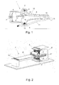
Figure 1 shows an embodiment of an AMPG device comprising a plate spring as a first spring member and two conical helical springs as limiting springs. -
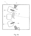
Figure 1A shows an embodiment where three bobbins are used. -
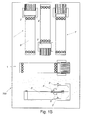
Figure 1B shows a printed circuit board where several AMPG devices are mounted. -
Figure 2 shows an embodiment of an AMPG device with two plate springs as limiting springs, and two oscillating magnets. -
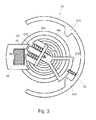
Figure 3 shows an embodiment of an AMPG device having a configuration which is flat and comprises a spiralspring. -
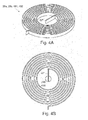
Figure 4 A-B shows a spiral spring comprising a limiting spring member. -
Figure 5 A-C shows an embodiment where the AMPG device has a cylindrical form and collection of acceleration components is enabled in the transversal direction of the AMPG device, infigures 5B and5C the AMPG device is shown in a split view where it has been cut in half in the longitudinal direction for better view, except for some parts comprising the magnetic holder, magnets, and spiral springs. -
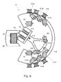
Figure 6 shows an embodiment of an AMPG device where the spiral spring infigure 3 is replaced with magnetic springs instead. -
Figure 7 A-C shows an embodiment of an AMPG device where the AMPG device has a cylindrical form, the AMPG device has a oscillating mass moving in the longitudinal direction of the device for collection of acceleration components in the longitudinal direction of the device, infigures 7B and7C the AMPG device is shown in a split view where it has been cut in half in the longitudinal direction for better view, except for some parts comprising the magnetic holder, magnets, and helical springs. -
Figure 8 A-B shows variants of an electrical scheme possible to use with or in an AMPG device. -
Figure 9 shows another electrical scheme possible to use with or in an AMPG device. -
Figure 10 shows a diagram of measured frequencies of an application in which an AMPG device can be used and optimized. - In the description below are several preferred embodiments of AMPG devices, described. This description should not be taken as limiting.
- A first preferred embodiment of the said invention is provided in
Figure 1 , where an AMPG (Accumulating Motion Pulse Generator)device 1 for generation of energy is provided.Said device 1 hasplate spring 8, made preferably of spring steel, steel or any other material with the appropriated spring properties, saidplate spring 8 is at one end attached at anattachment point 10. Thispoint 10 is called the base. At the opposing end threemagnets magnet holder 17. Theholder 17 is mounted on saidplate spring 8. Themagnets magnets device 1. The direction of the magnetic field leaving or coming out of the poles of respective magnet, 4,5, 16. One end of theplate spring 8 is arranged to move freely in a sector of thespring 8 deflection, circle like. Said deflection is limited by two limitingsprings springs plate spring 8. - In the
device 1 is also abobbin 9 provided. The bobbin has alaminated core 6 inside. Thecore 6 is made preferably from µ-metal, or any other material with good magnetic permeability. Thecore 6 has a gap in which themagnets plate spring 8 moves due to exposure of acceleration components. Thedevice 1 is shown as an externally mounted AMPG device, being mounted on aholder 11. The device also has a protectingshell 12 enclosing the inner electricity generating members of thedevice 1. Thedevice 1 is attached to theholder 11 in at least twopoints - The
AMPG device 1 comprises also aconnector 7 for connection with an electric load. When exposed to an acceleration component in a path of mobility of theplate spring 8, the moving mass of thedevice comprising magnets plate spring 8. As the kinetic energy approaches zero the movement is slowed down until all the kinetic energy, neglecting the converted electrical energy and losses such as internal friction, has been stored as potential energy in theplate spring 8. Then the potential energy of saidplate spring 8 accelerates the moving mass comprising themagnets magnets core 6 which is associated with saidbobbin 9, electricity is generated. Due to the shown configuration wherein the magnets are moving outside thebobbin 9, but closing the magnetic circuit instantaneously, in the gap in thecore 6 and because of the abrupt changing of the magnetic field due to the reversed configuration of themagnets magnets core 6 in reversing direction for each internal transfer between kinetic energy and potential energy and vice versa. - In some cases the kinetic energy is too large to be stored in the
plate spring 8. In such case themagnet holder 17 will alternating transfer the excess kinetic energy to a limitingspring figure 1 the limitingspring 2 that receives the kinetic energy and stores that as potential energy and resend this energy into the moving parts of theAMPG device 1. This use of limitingsprings figure 1 . - In an alternative embodiment schematically shown in
figure 1A , of the AMPG device offigure 1 , the single bobbin is exchanged with threeseparate bobbins 9"a-c. One of thebobbins 9" b is without µ-metal core and is positioned in the center of oscillating path of the moving mass, equal to the position of equilibrium of the moving mass when not moving. The other two bobbins are equipped with µ-metal cores in the same way as shown infigure 1 . Thebobbins 9"a, 9"c withcores 6"a, 6"c are located at each end of the oscillating path of the moving mass. This type of embodiment will cover a wider spectrum of amplitudes and a wider spectrum of frequencies. - In an alternative embodiment, not shown, of the AMPG device of
figure 1 , is thepoint 15 the only attachment point. The saidpoint 15 is attached in a hinged manner for example with an axis in a bearing or in another known way. By the saidpoint 15 acting as a hinge thewhole AMPG device 1 is arranged to be movable in a circle sector manner up to a limiting sector support. This means an acceleration component with low frequncy can move essentially the total mass of the AMPG device and transform the acceleration to a higher frequency with regard to internally moving parts. The whole AMPG device will then in a clattering manner transform said acceleration component into mechanical energy altering between kinetic energy, potential energy and finally transformed to electrical energy. The size of these energies will of course be affected by a minimized amount of losses such as friction, internal friction, heat and magnetic flux losses. - In a further alternative embodiment, shown schematically in
figure 1B , of theAMPG device 1 offigure 1 , said device is provided in a form where the base connected to the moving parts and the bobbin with the µ-metal core and the limiting springs 2' are directly mounted on a printedcircuit board 700. In this case the cover can be left out. The limiting springs 2' can optionally be in the form of rubber cloths springs or plate springs as shown infigure 2 . The limiting springs 2' in thefigure 1B have been left out on two of the shown devices for a better view, but it should be understood that they are normally present. This kind of embodiment is suitable to be miniaturized and multiplied. A plurality of these AMPG devices of this embodiment can by advantage be mounted directly on a printed circuit board, for adaptation to desired amount of electrical energy and to use all available empty space on the printed circuit board. Optionally they are mounted in different directions for collecting acceleration components of different directions. -
Figure 3 shows an embodiment of anAMPG device 21 of said invention, this embodiment is particularly favorable when the space is limited in one dimension since it can be made very flat. But of course it's scaleable in all dimensions. TheAMPG device 21 comprises a pair ofspiral spring magnets holder 212 in a clamped manner. Theholder 212 is part of a laminated µ-metal core and has the shape of an E. This part can off course be made of any other magnetically permeable metal alloy having the right properties. For conducting the magnetic field in the best way the aisles of the E are rounded to narrow the distance to the other fixed part of the laminated µ-metal core 26. The fixed part of saidcore 26 has also the shape of an E. The fixed part of the core 26, has also a matching rounded shape of the section close to the path of mobility of theholder 212. Thereby can the distance be minimized between theholder 212 and thecore 26. TheAMPG device 21 of said embodiment accordingly has the advantage that the gap between the core 26 and themagnetic holder 212, which conducts the magnetic field from themagnets rotor 215,holder 212,magnet holder 212 is mounted on arotor 215. Therotor 215 has an eccentric mass balance to optimize the ability to collect acceleration components. A limitingspring 22 is arranged in therotor 215. The limitingspring 22 is preferably as above made from spring steel, steel or any other appropriate material such as plastic material or rubber with good spring properties. This limitingspring 22 is arranged to act on thestops rotor 215. The device further comprises abobbin 29. Therotor 215 has anaxis 210 which is journalled in bearing, such as a ball bearing or a needle bearing, or another bearing with low friction, or a set of such bearings. Theaxis 210 is placed eccentrically in therotor 215, with regard to the mass balance, i.e. so that the masses on each side of theaxis 210 are differing. The pair ofspiral springs rotor 215. Thereby it acts on therotor 215 when, saidAMPG device 21 is exposed to an acceleration component in a direction which is essentially tangential to the circular sector moving path of therotor 215. In the same manner, as described for the first embodiment ofFigure 1 , the pair of spiral springs 28a and 28b will store kinetic energy as potential energy. If the kinetic energy is to large to be stored by the pair ofspiralspring spring 22. The limitingspring 22 will cooperate with thestops springs springs magnets core 26, and thebobbin 29, and a new build up of potential energy will take place in an oscillating manner so that it changes the direction of the magnetic flow in the second part of thelaminated core 26, which passes through the coil of conducting material such as copper wire, abobbin 29. The resulting oscillating movement will continue until all potential and kinetic energy has been transformed into electrical energy, neglecting losses. In thedevice 21 the difference in spring constant of the limitingspring 22 and the spring 28 is of the same order as mentioned fordevice 1 above. Thedevice 21 can as mentioned above also be mounted on a printed circuit board. - In
figure 5A-C is anotherdevice 41 shown. In this device the cylindrical form has been a limiting factor since the aim has been to comprise the AMPG abilities in a standard battery package such as D, C, AA, AAA, AAAA, E-Block or any other battery form of known kind. ThisAMPG device 41 comprises,magnets 44 mounted in a essentiallycylindrical holder 425, abobbin 49, a first printedcircuit board 423 comprising semiconductor electronics, rectifier bridge with diodes and contact components to the battery positive pole a second printedcircuit board 424 comprising accumulation electronics andultra capacitors 420 and contact components to the battery negative pole, and anaxis 410 fixed on the respective printedcircuit boards axis 410 is fixed and the moving mass of the AMPG comprising themagnets 44 and theholder 425 are connected to the axis withbearings 422. Said axis is also possible to attach to the respective end of the body structure. Further comprised areeccentric weights 421, spiral springs 481 and 482 one mounted in clockwise direction and the other in counter clockwise direction. - Said spiral springs comprise a limiting
spring member 22", as seen infigure 4A-B . The limitingspring member 22" acts when the spiral spring on one end has been fully wound up. The function of the limitingspring member 22" is essentially that of a plate spring. The limitingspring member 22" is also the attachment point to theeccentric weight 421, also connected to themagnetic holder 425. - The
individual magnets 44, are orientated in a cylindrical system so that their magnetic flux is oriented radially. This means that eachmagnet 44 is oriented radially with regard to thecylindrical holder 425. Themagnets 44 are essentially oriented perpendicular to the longitudinal windings of thebobbin 49. I.e. at the outer perimeter of theholder 425, are all magnets configured with the same polarity. And consequently the reversed polarity of eachmagnet 44 is pointed at the center axis of themagnetic holder 425. - Preferably the
magnets 44 are made from Neodymium or other suitable magnetic material such as ferrite. As is shown inFigure 5B-C there arecylindric magnets 44 circumferentially mounted on the perimeter of thecylindric holder 425. Themagnets 44 can of course be replaced by one single magnet, preferably with a solenoidal shape so that the holder can be dispensed with it. Theholder 425 can optionally be fitted withmagnets 44 in non regular manner so that the eccentric mass balance is augmented. - The
outer shell 426 of theAMPG device 41 is preferably made in a high friction material such as elastomer, rubber, or other materials having the ability to add friction to the outer shell. This high friction counteracts rotation of thewhole AMPG device 41, relative to the AMPG holder, when exposed to acceleration components trying to rotate it. This shell material will also have the function as an insulator. - When the
device 41 is exposed to an acceleration component in the transversal direction, the moving parts of theAMPG device 41 will move in a manner explained above. Thesprings spring member 22" as seen infigure 4A , the excess of kinetic energy will be stored in the limitingspring member 22", acting as a limiting spring within therespective spiral spring spiral spring -
Eccentric weights 421 will ad imbalance to the moving parts making, as mentioned above, it possible to collect acceleration components in a transversal direction. Saidbobbin 49 has a coiling in the AMPG device's 41 longitudinal direction. The material of thebobbin 49 is preferably copper, or other suitable electricity leading material. - Another embodiment of an
AMPG device 31 is shown inFigure 6 . Thisdevice 31 has many features in common with theAMPG device 21 discussed above.Rotor device 315,magnets holder 312,bobbin 39,core 36, andaxis 310 with bearing are essentially the same as theAMPG device 21 inFigure 2 . ThisAMPG device 31 has main springs and limiting springs being in the form of magnet springs 381 382. TheMagnets magnets point magnets - A number of smaller
extra bobbins 319 are arranged outside themagnetic springs 313a-c and 314a-c. Thebobbins 319 are arranged to collects changes in the magnetic field from the magnets of themagnetic springs springs spring 316 arranged on therotor 315. The extra limitingspring 316 is made in for example steel, spring steel or rubber or any other elastic material. The function of theAMPG device 31 is essentially the same as that of the device ofFigure 3 . Themagnets magnets AMPG device 31 performs an oscillating movement, when exposed to an acceleration component in the moving direction of said moving parts. When the kinetic energy in therotor 315 is to large to be collected by themagnetic springs spring magnets spring 316 will act as collector of the last excess of kinetic energy. Said rotor assembly has anaxis 310 placed eccentrically as mentioned above so that it will rotate when exposed to acceleration components in the direction of possible motion path. TheAMPG device 31 is as the device inFig 3 , very easy to produce flat. One or a plurality ofdevices 31 can as mentioned above also be mounted on a printed circuit board. All the bobbins are electrically connected so that all electrical energy will be taken care off - The shown embodiment of
Figure 7A-C shows anAMPG device 51 for collection longitudinal acceleration components. The outer cylindrical shape of thedevice 51 is the same as that mentioned above fordevice 41. Comprised in thisembodiment 51 aremagnets 54, amagnet holder 525, suspended in pretensioned helical springs 58. Further comprised is abobbin 59. And also comprised are limitingsprings - The
bobbin 59 is coiled transversally. Theholder 525, which is preferably cylindrical, is freely suspended in the pretensionedhelical springs 58 with a preferably cylindrical gap to the outer cylindrical structure,bobbin chassis 591. This means that theholder 525 comprising themagnets 54 is arranged to move essentially without friction. Eachmagnet 54 is mounted in the same way as in the embodiment ofFigure 5A-C . The limiting springs 52, 53 are preferably plate spring roundels. The material of the limitingsprings bobbin chassis 591 in each end of thebobbin chassis 591. - When said
magnets 54 are moved relatively to said bobbin in a perpendicular manner, a current will be induced an electrical energy is achieved from kinetic energy of themagnetic holder 525, andmagnets 54, assembly. The acceleration component in a longitudinal direction of theAMPG device 51, can be so large that thehelical springs 58 cannot store all the kinetic energy as potential energy. In that case the limitingsprings AMPG device 51 moves in the longitudinal direction due to an exposure of an acceleration component in that direction, the magnetic holder will if the component is strong enough bounce against the limiting springs in an oscillating manner, the frequency of this oscillation will be kept as long as these bounces occur. This is due to the fact that the spring constant of the limitingsprings helical springs 58 in the order as mentioned above. The helical springs 58 are mounted on the printedcircuit boards helical springs 58 can be mounted in each the end of the body structure of theAMPG device 51. Comprised in this embodiment are of course all the electrical components mentioned in theembodiment 41, and of course canembodiment 51 have a single magnet and magnets of neodymium and other material configurations as mentioned earlier in the other embodiments. - The mentioned embodiments above shall not be taken as limiting the scope of the invention to these exact embodiments. For example to collect acceleration components in different directions, the
AMPG devices Figure 1B as an example. - For all embodiments of the AMPG devises within this invention is the following applicable: They can be used as motion sensors with high accuracy and they are self supplying with power. They can for example be used as wireless burglar alarms, etc.
- For all embodiments of the AMPG devises within this invention is the following applicable: They can be used as either passive motion dampers or active motion dampers. In case of passive use, the AMPG device will suppress the unwanted motion in accordance to the connected amount of load.
In case of active use, the AMPG device will suppress the unwanted motion in accordance to the connected breaking power signal supplied to the active damper. The breaking power signal can be the result of another AMPG device used as sensor when the signal has been amplified. They can for example be used as active noise reduction in airplanes and vehicles, etc. - For all embodiments of the AMPG devices in the thought of the invention, electronics equipment is comprised so as to take care of the generated electrical current. In particular this is important should a capacitor or an ultra capacitor will be used. Typical arrangement of the electronic hardware configuration needed can be studied in
figures 8 and9 , where a person skilled in the art of electronics directly sees how the electronics can be disposed in association with any of the AMPG devices discussed. It should be understood that the mentioned ultra capacitor of course can be an ordinary capacitor. - For all embodiments of the AMPG devises within this invention is the following applicable: They can be used as oscillating motors which are generating a oscillating movement when they are powered with an oscillated signal.
- They can for example be used as recoil or movement generators in computer game devices to make the experience more realistic.
- The invention also comprises a method of optimizing the retrievable electrical power from AMPG devices. It has been shown in laboratory testing that the two characteristic natural frequencies of the AMPG's are highly important for the most efficient use of the AMPG's. To reach the most efficient use of the AMPG devices by matching those frequencies so that they are equal to or close to the most significant frequencies of the application in which they will be used. The common meaning of the methods described below is:
- adapting the AMPG device's natural frequencies even called the AMPG device's resonance frequencies to the detected frequency ranges on the wanted application by changing the spring constants of at least one comprised spring member and/or by changing the moving mass in magnitude and/or changing the moving mass in position of the said AMPG device.
- using the harmonized AMPG device in said measured frequency interval of said application on the same measured positions.
- For some embodiments of the AMPG devices, those which are featured with a significant ability to effectively bounce between the limiting spring/limiting spring members, and where the function of the main spring/main spring members are basically to orient and support the moving mass/masses in the appropriate path, the need of tuning is concentrated to the most significant resonance frequency measured on the actual application. In those cases where this is applicable it is only necessary to harmonize the AMPG device's highest natural frequency, so-called f (resonance-high) and the f (resonance-low) is of minor importance. When following the stepwise method below, the method will be changed in step 2.3 to just: select the resonance frequency representing the highest content of mechanical energy, and this resonance frequency mentioned in 2.3, will set the parameters and is the goal frequency for dimensioning the f(resonance-high) of the AMPG device. All steps regarding f(resonance-low) can consequently be ignored.
- To optimize the AMPG device's efficiency, the following stepwise method is calculated.
- 1. Measurements on the application
- 1.1 If the resonance frequencies and its contents of energy of the application, when it is running under its typical profile, are unknown, shall the following measurements according to 1.1.1, 1.1.2 be performed, otherwise proceed with 2.3.
- 1.1.1 Measure the complete frequency spectrum on the applications appropriate potential AMPG device attachment positions in X-, Y- and Z-directions. Use accelerometers connected to a frequency spectrum analyser.
- 1.1.2 Store the measured data, and present the result graphical for further analysis.
- 1.1 If the resonance frequencies and its contents of energy of the application, when it is running under its typical profile, are unknown, shall the following measurements according to 1.1.1, 1.1.2 be performed, otherwise proceed with 2.3.
- 2. Analyses of measurements
Seefigure 10 , which is representing one example of a measured application in one direction.- 2.1 Find the most significant resonance frequencies for the application system.
- 2.2 Analysis the amplitude of the founded resonance frequencies.
- 2.3 Select the two resonance frequencies representing the highest content of mechanical energy.
- 3. Dimensioning of the natural frequencies of the AMPG device
- 3.1 The lowest of the two resonance frequencies mentioned in 2.3, will set the parameters and is the goal frequency for dimensioning the f (resonance-low) of the AMPG device.
- 3.2 Use the formula, f(resonance) = (1/(2xπ))x√(k / m), to calculate the relation between the moving mass, m and k (main).
- 3.3 Determine the moving mass, m and solve out k (main) or determine the k (main) and solve out the moving mass.
- 3.4 The highest of the two resonance frequencies mentioned in 2.3, will set the parameters and is the goal frequency for dimensioning the f (resonance-high) of the AMPG device.
- 3.5 Use the formula, f(resonance) = (1/(2xπ))x√( k/ m), to calculate the relation between the moving mass, m and k (total) = f ( k (main), k (limiting)), where k (total) is the result of the main spring/mainspring members spring constant together with the limiting spring/limiting spring members spring constant, when those springs are at the moving mass returning point (also possible to be measured as, the total force divided by the total deflected length, when the moving mass/masses are forced at the returning point). Due to the moving mass, m and k (main) are known from 3.3, it is possible to solve out k (limiting).
- 4. Dimensioning of the spring elements for the AMPG device
- 4.1 The easiest way to harmonize the AMPG device's resonance frequencies when the moving mass is given is to match the AMPG device moving mass with spring elements designed after the calculated spring constants. This can be done either with selection of suitable standard springs with specified spring constants in the unit Newton/meter, [N/m] or customizing the spring elements, using known standard formulas within mechanical engineering, such as:

Where:- F = Force in Newton, [N]
- k = Spring constant, [N/m]
- l = Length of deflection [m]
- σ = Mechanical stress [MPa]
- E = Elasticity modulus [MPa]
- ε = Mechanical strain
- A = Cross section area of the spring element [m2 ]
- 4.2 For more complex spring elements other methods with for example elementary cases formulas or FEM-calculation can be used. It is also possible to in a practical way tune the spring elements with a dynamometer and iterated machining operations.
- 4.1 The easiest way to harmonize the AMPG device's resonance frequencies when the moving mass is given is to match the AMPG device moving mass with spring elements designed after the calculated spring constants. This can be done either with selection of suitable standard springs with specified spring constants in the unit Newton/meter, [N/m] or customizing the spring elements, using known standard formulas within mechanical engineering, such as:
- 5. Dimensioning of the moving mass elements for the AMPG device
- 5.1 The easiest way to harmonize the AMPG device's resonance frequencies when the spring constants are given is to match the AMPG device's spring elements with the calculated mass. Adding weight means that the resonance frequencies will decrease. Removing weight means that the resonance frequencies will increase. This can be done with a system of attaching/detaching a set of elemental weights.
- 6. Categorised AMPG devices
- 6.1 In a further use of the method according to step 1-5 prefabricated AMPG devices will be tuned and categorised within the most common frequency spectrums. This will simplify the procedure. When step 1-2 is performed it is possible to select and order from a systematically arranged catalogue of specified AMPG devices where the two characteristic resonance frequencies can be found in the nearest interval.
- 6.2 In case of several widely spread resonance frequencies is present, it is preferable to use a number of AMPG devices covering the most usable frequency areas in the actual application.
- 7. Usage of adjustable AMPG devices
The said tuning can also be done with adjustments of the spring elements or the magnitude and/or position of the moving mass on a universal AMPG device. In a universal AMPG device it is possible to adjust the two characteristic natural frequencies of the AMPG devices within two intervals, the high- and the low resonance frequencies spectrums.- 7.1 Continues adjustment. This can be made through adjusting the spring constants in the main spring and/or limiting springs by changing the deflection length of the said spring elements. The natural frequencies of the AMPG device will decrease with larger deflecting lengths and they will increase with smaller deflecting lengths.
- 7.2 Discrete adjustment. In another embodiment of a universal AMPG device the adjustment of the natural frequencies can be done by a set of prearranged spring elements. Those can be installed and used in a combination, which result in the wanted resonance frequencies within a number of discrete steps.
- 7.3 Continues adjustment. In another embodiment of a universal AMPG device the adjustment of the natural frequencies can be done by adjusting the moving mass in an infinite way with varying the content in a balance container, such as varying the amount of liquid in a volume.
- 7.4 Continues adjustment. In another embodiment of a universal AMPG device the adjustment of the natural frequencies can be done by adjusting the position of the moving mass in regard to the revolving axis. This will vary the inertia for the system and affect the natural frequencies.
- 7.5 Continues adjustment. In another embodiment of a universal AMPG device the adjustment of the natural frequencies can be done by moving the axis of rotation of the AMPG device. This will vary the inertia for the system and affect the natural frequencies.
- 7.6 Discrete adjustment. In another embodiment of a universal AMPG device the adjustment of the natural frequencies can be done by a set of prearranged weights. Those can be installed and used in a combination, which result in the wanted resonance frequencies within a number of discrete steps.
- 8. Adjusting the load connected to the AMPG devices
For applications where the frequency pattern is very regular and predicted, it is possible to optimize the electrical output by adjusting the load connected to the AMPG devices. This method can be applied to all embodiments of the AMPG devices.- 8.1 Sinusoidal cases. To make it possible to reach maximum output, when the sinusoidal vibration is limited in content of energy, it is highly effective to adjust the load to a level just below the limit when the moving mass stops vibrating. The reason why this is doable, is when the load is increased the moving mass will be affected with a larger breaking force slowing down the movement, i.e. when the load is decreased the moving mass will be effected with a smaller breaking force which allows the moving mass to continue oscillating when the amount of energy content in the vibration is low.
- 8.2 In another embodiment of the AMPG device, it comprises an electronic circuit which is measuring the amplitude of the output signal, and adjust the resistance connected to the circuit board so that the output will always be at maximum level, a so-called regulator.
- 8.3 Random vibration cases. To make it possible to reach maximum output, when the random vibration is limited in content of energy, it is highly effective to adjust the load to a level just below the limit when the moving mass stops vibrating, but this will only be the case in intermittently intervals. Within those intervals the same regulating technique is used, as in the sinusoidal case 8.1-8.2.
- 8.4 The method described under
step 8, still requires at least the previous optimizing steps described under step 1-3.
- In
figure 10 is shown stored measured data with graphical result presented for analysis.
The graph shows a plot of the spectrum of vibration power density [g2/Hz] versus the frequency [Hz] on the measured point of the application. In picture below are three significant resonance frequencies shown. They are arranged in the following order, f (1)- f (3), representing the most significant resonance frequencies with regard to the content of energy. This means that f (1) represents f (resonance-low) and f (2) represents f (resonance-high). f (3) is a resonance frequency with less amount of energy and will not be used. Depending of which type of AMPG device we are dealing with, shall f(1) and f (2) be utilized on the most efficient way, taking care of the basic role in the method mentioned in the beginning of the description.
Claims (31)
- An AMPG device for generation of electrical energy, comprising, a bobbin, at least one first magnet, and at least one first spring member, wherein said first magnet is arranged to be movable together with said first spring member, said device is arranged so that when exposed to an acceleration component in a possible path of mobility of said first magnet, said first magnet will due to its association with said first spring member arranged to move in an oscillating manner in relation to said bobbin, so as to generate electrical energy, characterized in that said device comprises a second spring member at a limiting position of said mobile magnet's path of mobility, for limiting said path of mobility.
- The AMPG device of claim 1 wherein the second spring has an equal or higher spring constant than the spring constant of the first spring member.
- The AMPG device one of the claims 1-2 wherein the said first magnet comprises Neodymium.
- The AMPG device of one of the claims 1-3 wherein said second spring comprises a helical spring.
- The AMPG device of one of the claims 1-3 wherein said second spring member comprises a plate spring.
- The AMPG device of one of the claims 1-3 wherein said second spring comprises a cloth, such as a rubber cloth.
- The AMPG device of one of the claims 1-3 and 5 wherein said second spring comprises second magnets, with reversed magnetic field to each other so as to act as a spring.
- The AMPG device of one of the claims 1-7 wherein said first spring comprises a spiral spring.
- The AMPG device of claim 8 wherein said second spring comprises a plate spring member comprised in said first spring.
- The AMPG device of one of the claims 1-6, 8-9 wherein said second spring comprises a combination of second magnets and mechanical springs.
- The AMPG device of claim 7 or 11 wherein said second magnets comprises Neodymium.
- The AMPG device of one of the claims 1-11 above wherein the outer shape of the AMPG device is arranged so that said AMPG device is mountable in a standard holder for a battery such as a D, C, A, AA, AAA or AAAA E-block battery or any other standard battery size, for use in a standard battery demanding application.
- The AMPG device of claims 12 wherein the outer shell of the AMPG device comprises a high friction material.
- The AMPG device of claim 13 wherein the shell comprises elastomer.
- The AMPG device of claim 13 wherein the shell comprises rubber.
- The AMPG device of one of the claims 1-15 wherein the device is optimized for collection of acceleration components in its transversal direction by comprising a rotor with an eccentric mass balance, said rotor comprises said first magnet.
- The AMPG device of claim 16 wherein the first spring member is a spiral spring associated with said rotor.
- The AMPG device of claim 16 or 17 wherein the first spring member comprises a pair of spiral springs, oriented towards each other in opposite direction.
- The AMPG device of one of the claims 1-15 wherein the device is optimized for collection of acceleration components in its longitudinal direction, by associating said first magnet with a spring member of helical type allowing said first magnet to move close to said bobbin in the longitudinal direction of said device.
- The AMPG device of one of the claims 1-19 wherein the device comprises a bobbin having a core arranged to guide the changing magnetic field through the coil in the bobbin.
- The AMPG device of claim 20 wherein the core is laminated.
- The AMPG device of any of claim 20-21 wherein the core comprises µ-metal.
- The AMPG device of any of the claims above wherein one first magnet is mounted close to another first magnet with essentially the reversed magnetic field direction so as to provide for achieving a quick change of magnetic field, when the first magnets with reversed magnetic fields passes the gap in the core which passes through the bobbin.
- An AMPG device of claim 23 wherein comprised is a plurality of the first magnets are mounted close to each other at equally distances between each other, with alternating magnetic field directions.
- A printed circuit board characterized in that said printed circuit board comprises at least one AMPG device as claimed in any of the claims 1-24.
- An AMPG device assembly comprising at least two of the AMPG devices according to any of the claims 1-25 characterized in that the AMPG devices are mounted angularly displaced relative to each other, whereby the AMPG assembly is able to collect acceleration components in more than one direction.
- Method of to optimize the electrical output from an AMPG device according to any of the claims 1-24, comprising the steps of,- determining a frequency range of the vibrations emerging from the application in which the AMPG device is intended to be used,- adapting at least on of the AMPG-device's resonant frequencies to the detected frequency range.- using the AMPG device in an application with vibrations in the frequency interval comprising said measured frequency of said application.
- Use of the AMPG device in any of the claims 1 - 24 wherein the AMPG device is used as a selfpowered motion sensor.
- Use of the AMPG device in any of the claims 1-24 wherein the AMPG device fed with electrical current and thereby is used as an oscillating electrical motor.
- Use of the AMPG device in any of the claims 1-24 wherein the AMPG device is connected to an amount of load, suppressing unwanted motions so that it will work as a passive damper.
- Use of the AMPG device in any of the claims 1-24 wherein the AMPG device is suppressing unwanted motions in accordance to a connected power signal so that it will work as an active damper.
Priority Applications (3)
| Application Number | Priority Date | Filing Date | Title |
|---|---|---|---|
| EP06126914A EP1936787B1 (en) | 2006-12-21 | 2006-12-21 | AMPG device for generation of electrical energy from vibrations, an AMPG device assembly, and a method to optimize the generation of said electrical energy |
| AT06126914T ATE549785T1 (en) | 2006-12-21 | 2006-12-21 | AMPG DEVICE FOR GENERATING POWER FROM VIBRATIONS, AMPG DEVICE ARRANGEMENT AND METHOD FOR OPTIMIZING SAID POWER GENERATION |
| US12/003,045 US8304937B2 (en) | 2006-12-21 | 2007-12-19 | AMPG device for generation of electrical energy from vibrations, an AMPG device assemby, and a method to optimize the generation of said electrical energy |
Applications Claiming Priority (1)
| Application Number | Priority Date | Filing Date | Title |
|---|---|---|---|
| EP06126914A EP1936787B1 (en) | 2006-12-21 | 2006-12-21 | AMPG device for generation of electrical energy from vibrations, an AMPG device assembly, and a method to optimize the generation of said electrical energy |
Publications (2)
| Publication Number | Publication Date |
|---|---|
| EP1936787A1 true EP1936787A1 (en) | 2008-06-25 |
| EP1936787B1 EP1936787B1 (en) | 2012-03-14 |
Family
ID=37998334
Family Applications (1)
| Application Number | Title | Priority Date | Filing Date |
|---|---|---|---|
| EP06126914A Active EP1936787B1 (en) | 2006-12-21 | 2006-12-21 | AMPG device for generation of electrical energy from vibrations, an AMPG device assembly, and a method to optimize the generation of said electrical energy |
Country Status (3)
| Country | Link |
|---|---|
| US (1) | US8304937B2 (en) |
| EP (1) | EP1936787B1 (en) |
| AT (1) | ATE549785T1 (en) |
Cited By (7)
| Publication number | Priority date | Publication date | Assignee | Title |
|---|---|---|---|---|
| US9843248B2 (en) * | 2015-06-04 | 2017-12-12 | David Deak, SR. | Rocker action electric generator |
| CN108240309A (en) * | 2016-12-27 | 2018-07-03 | 三美电机株式会社 | Power generator and electronic equipment |
| CN109927492A (en) * | 2017-12-15 | 2019-06-25 | 比亚迪股份有限公司 | Device for monitoring tyre pressure, tire and vehicle |
| US11251007B2 (en) | 2017-10-30 | 2022-02-15 | Wepower Technologies Llc | Magnetic momentum transfer generator |
| USRE49840E1 (en) | 2012-04-06 | 2024-02-13 | Wepower Technologies Llc | Electrical generator with rotational gaussian surface magnet and stationary coil |
| US11973391B2 (en) | 2019-11-21 | 2024-04-30 | Wepower Technologies Llc | Tangentially actuated magnetic momentum transfer generator |
| US12062965B2 (en) | 2019-07-20 | 2024-08-13 | Wepower Technologies Llc | Offset triggered cantilever actuated generator |
Families Citing this family (7)
| Publication number | Priority date | Publication date | Assignee | Title |
|---|---|---|---|---|
| WO2010138200A1 (en) * | 2009-05-29 | 2010-12-02 | Bae Systems Information And Electronic Systems Integration Inc. | Apparatus and method for monitoring projectile emission and charging an energy storage device |
| DE102010020315A1 (en) * | 2010-05-12 | 2011-11-17 | Minebea Co., Ltd. | Generator for converting mechanical energy into electrical energy for remote controller of e.g. TV, has oscillator secured at swing arm such that oscillator is moved by elastic deformation of arm and arm is firmly connected with cabinet |
| CN104054231A (en) * | 2011-11-21 | 2014-09-17 | 摩西·英迪格 | Electric motors operated by random motion |
| WO2015083339A1 (en) * | 2013-12-06 | 2015-06-11 | パナソニックIpマネジメント株式会社 | Power generation unit |
| CN105098897A (en) * | 2015-07-30 | 2015-11-25 | 京东方科技集团股份有限公司 | Wearable device and terminal |
| US11362575B1 (en) * | 2019-08-27 | 2022-06-14 | Louisiana Tech Research Corporation | Spring assisted magnetic energy harvester |
| SE544142C2 (en) | 2019-10-23 | 2022-01-11 | Revibe Energy Ab | Magnet enabled power generator |
Citations (17)
| Publication number | Priority date | Publication date | Assignee | Title |
|---|---|---|---|---|
| GB719977A (en) * | 1951-09-25 | 1954-12-08 | Antoine Gazda | Improvements in or relating to self-winding timepiece |
| US3984707A (en) * | 1973-07-13 | 1976-10-05 | Mcclintock Richard D | Spring return linear signal generator |
| US4709176A (en) | 1986-07-31 | 1987-11-24 | Ridley William E | Magnetic battery |
| DE19520521A1 (en) | 1994-06-13 | 1995-12-14 | Gen Electric | Vibration to electrical energy converter esp. to supply sensors and radio transmitters in waggons and containers |
| DE29618105U1 (en) | 1996-10-18 | 1997-02-20 | TR Elektronic GmbH, 84533 Haiming | Energy generating device as a battery or accumulator replacement |
| JPH11234913A (en) * | 1998-02-19 | 1999-08-27 | Seiko Epson Corp | Power supply unit, power supply package, and electronic device incorporating them |
| EP1085383A1 (en) * | 1999-09-17 | 2001-03-21 | Eta SA Fabriques d'Ebauches | Anti-shock device for a power generator driven by an oscillating weight |
| DE10055908A1 (en) * | 2000-11-10 | 2002-05-23 | Erhard Otte | Device for obtaining electrical energy has end stops that temporarily store inertial mass kinetic energy released during braking as potential energy, release it to mass again as it leaves stop |
| WO2003071664A1 (en) | 2002-02-19 | 2003-08-28 | Rockwell Scientific Licensing, Llc | Multiple magnet transducer |
| JP2005086902A (en) * | 2003-09-08 | 2005-03-31 | Katsumi Ikeda | Cellular phone with generator |
| WO2005057760A1 (en) * | 2003-12-12 | 2005-06-23 | Zf Friedrichshafen Ag | Chassis component |
| WO2005106244A1 (en) * | 2004-04-10 | 2005-11-10 | Bo-Young Jeong | Self-generator for transforming tiny kinetic energy into electric energy |
| US20050280218A1 (en) * | 2004-06-18 | 2005-12-22 | Parison James A | Electromechanical transducing |
| WO2006010937A1 (en) | 2004-07-27 | 2006-02-02 | British Telecommunications Public Limited Company | Method and system for packetised content streaming optimisation |
| EP1626144A2 (en) * | 2003-10-22 | 2006-02-15 | ArvinMeritor Light Vehicle Systems (UK) Ltd | Actuator assembly |
| WO2006072539A2 (en) * | 2005-01-07 | 2006-07-13 | Continental Teves Ag & Co. Ohg | Tyre module and tyre comprising a module of this type |
| WO2006109033A1 (en) | 2005-04-12 | 2006-10-19 | Perpetuum Ltd., | Generator for converting mechanical vibrational energy into electrical energy |
Family Cites Families (17)
| Publication number | Priority date | Publication date | Assignee | Title |
|---|---|---|---|---|
| US3470403A (en) * | 1967-05-10 | 1969-09-30 | Ahmet K Bey | Electric motor with torque amplified output |
| US3500080A (en) * | 1967-09-18 | 1970-03-10 | Ahmet K Bey | Oscillating electric motor |
| US4187452A (en) * | 1975-08-27 | 1980-02-05 | International Business Machines Corporation | Electromechanical torsional oscillator with resonant frequency and amplitude control |
| NL8802471A (en) * | 1988-10-10 | 1990-05-01 | Philips Nv | ENGINE COMPRESSOR UNIT. |
| US6704001B1 (en) * | 1995-11-17 | 2004-03-09 | Immersion Corporation | Force feedback device including actuator with moving magnet |
| FR2781938B1 (en) * | 1998-07-30 | 2003-09-19 | Hutchinson | ELECTROMAGNETIC MOTOR AND ACTIVE VIBRATION CONTROL DEVICE INCLUDING AT LEAST ONE SUCH MOTOR |
| US6262500B1 (en) * | 1999-10-05 | 2001-07-17 | Teikoku Tsushin Kogyo Co., Ltd. | Vibration generator |
| US7256518B2 (en) * | 2000-05-08 | 2007-08-14 | Gummin Mark A | Shape memory alloy actuators |
| DE10163544A1 (en) * | 2001-12-21 | 2003-07-17 | Bsh Bosch Siemens Hausgeraete | Electric motor and method for its production |
| US6906789B2 (en) * | 2003-06-02 | 2005-06-14 | Asml Holding N.V. | Magnetically levitated and driven reticle-masking blade stage mechanism having six degrees freedom of motion |
| US7358633B2 (en) * | 2004-02-23 | 2008-04-15 | Samsung Electro-Mechanics Co., Ltd. | Linear vibration motor using resonance frequency |
| US7378765B2 (en) * | 2004-08-09 | 2008-05-27 | Oriental Motor Co., Ltd. | Cylinder-type linear motor and moving part thereof |
| JP3996919B2 (en) * | 2004-08-20 | 2007-10-24 | 信越化学工業株式会社 | Permanent magnet motor |
| WO2006072253A1 (en) * | 2005-01-09 | 2006-07-13 | Benthin A/S | A machine for cutting fabric sheets for roller blinds |
| US7755227B2 (en) * | 2005-10-19 | 2010-07-13 | Alps Electric Co., Ltd. | Vibration generator |
| JP5089206B2 (en) * | 2006-03-17 | 2012-12-05 | エルジー イノテック カンパニー リミテッド | Linear vibrator |
| US20090072637A1 (en) * | 2007-09-13 | 2009-03-19 | Forcecon Technology Co., Ltd. | Airflow generator |
-
2006
- 2006-12-21 AT AT06126914T patent/ATE549785T1/en active
- 2006-12-21 EP EP06126914A patent/EP1936787B1/en active Active
-
2007
- 2007-12-19 US US12/003,045 patent/US8304937B2/en active Active
Patent Citations (17)
| Publication number | Priority date | Publication date | Assignee | Title |
|---|---|---|---|---|
| GB719977A (en) * | 1951-09-25 | 1954-12-08 | Antoine Gazda | Improvements in or relating to self-winding timepiece |
| US3984707A (en) * | 1973-07-13 | 1976-10-05 | Mcclintock Richard D | Spring return linear signal generator |
| US4709176A (en) | 1986-07-31 | 1987-11-24 | Ridley William E | Magnetic battery |
| DE19520521A1 (en) | 1994-06-13 | 1995-12-14 | Gen Electric | Vibration to electrical energy converter esp. to supply sensors and radio transmitters in waggons and containers |
| DE29618105U1 (en) | 1996-10-18 | 1997-02-20 | TR Elektronic GmbH, 84533 Haiming | Energy generating device as a battery or accumulator replacement |
| JPH11234913A (en) * | 1998-02-19 | 1999-08-27 | Seiko Epson Corp | Power supply unit, power supply package, and electronic device incorporating them |
| EP1085383A1 (en) * | 1999-09-17 | 2001-03-21 | Eta SA Fabriques d'Ebauches | Anti-shock device for a power generator driven by an oscillating weight |
| DE10055908A1 (en) * | 2000-11-10 | 2002-05-23 | Erhard Otte | Device for obtaining electrical energy has end stops that temporarily store inertial mass kinetic energy released during braking as potential energy, release it to mass again as it leaves stop |
| WO2003071664A1 (en) | 2002-02-19 | 2003-08-28 | Rockwell Scientific Licensing, Llc | Multiple magnet transducer |
| JP2005086902A (en) * | 2003-09-08 | 2005-03-31 | Katsumi Ikeda | Cellular phone with generator |
| EP1626144A2 (en) * | 2003-10-22 | 2006-02-15 | ArvinMeritor Light Vehicle Systems (UK) Ltd | Actuator assembly |
| WO2005057760A1 (en) * | 2003-12-12 | 2005-06-23 | Zf Friedrichshafen Ag | Chassis component |
| WO2005106244A1 (en) * | 2004-04-10 | 2005-11-10 | Bo-Young Jeong | Self-generator for transforming tiny kinetic energy into electric energy |
| US20050280218A1 (en) * | 2004-06-18 | 2005-12-22 | Parison James A | Electromechanical transducing |
| WO2006010937A1 (en) | 2004-07-27 | 2006-02-02 | British Telecommunications Public Limited Company | Method and system for packetised content streaming optimisation |
| WO2006072539A2 (en) * | 2005-01-07 | 2006-07-13 | Continental Teves Ag & Co. Ohg | Tyre module and tyre comprising a module of this type |
| WO2006109033A1 (en) | 2005-04-12 | 2006-10-19 | Perpetuum Ltd., | Generator for converting mechanical vibrational energy into electrical energy |
Non-Patent Citations (1)
| Title |
|---|
| M.N. PERUCCHI: "Problèmes concernant le spiral, rôle de petites déformations", JOURNAL SUISSE D'HORLOGERIE, 1966, pages 344 - 347, XP001219046 * |
Cited By (13)
| Publication number | Priority date | Publication date | Assignee | Title |
|---|---|---|---|---|
| USRE49840E1 (en) | 2012-04-06 | 2024-02-13 | Wepower Technologies Llc | Electrical generator with rotational gaussian surface magnet and stationary coil |
| US9843248B2 (en) * | 2015-06-04 | 2017-12-12 | David Deak, SR. | Rocker action electric generator |
| CN108240309B (en) * | 2016-12-27 | 2022-05-17 | 三美电机株式会社 | Power generation devices and electronic equipment |
| CN108240309A (en) * | 2016-12-27 | 2018-07-03 | 三美电机株式会社 | Power generator and electronic equipment |
| EP3343739A1 (en) * | 2016-12-27 | 2018-07-04 | Mitsumi Electric Co., Ltd. | Power generator and electronic device |
| US10826350B2 (en) | 2016-12-27 | 2020-11-03 | Mitsumi Electric Co., Ltd. | Power generator and electronic device |
| US11915898B2 (en) | 2017-10-30 | 2024-02-27 | Wepower Technologies Llc | Magnetic momentum transfer generator |
| US11251007B2 (en) | 2017-10-30 | 2022-02-15 | Wepower Technologies Llc | Magnetic momentum transfer generator |
| US12505969B2 (en) | 2017-10-30 | 2025-12-23 | Wepower Technologies Llc | Magnetic momentum transfer generator |
| CN109927492B (en) * | 2017-12-15 | 2020-11-06 | 比亚迪股份有限公司 | Tire pressure monitoring devices, tires, and vehicles |
| CN109927492A (en) * | 2017-12-15 | 2019-06-25 | 比亚迪股份有限公司 | Device for monitoring tyre pressure, tire and vehicle |
| US12062965B2 (en) | 2019-07-20 | 2024-08-13 | Wepower Technologies Llc | Offset triggered cantilever actuated generator |
| US11973391B2 (en) | 2019-11-21 | 2024-04-30 | Wepower Technologies Llc | Tangentially actuated magnetic momentum transfer generator |
Also Published As
| Publication number | Publication date |
|---|---|
| US8304937B2 (en) | 2012-11-06 |
| ATE549785T1 (en) | 2012-03-15 |
| EP1936787B1 (en) | 2012-03-14 |
| US20080174188A1 (en) | 2008-07-24 |
Similar Documents
| Publication | Publication Date | Title |
|---|---|---|
| US8304937B2 (en) | AMPG device for generation of electrical energy from vibrations, an AMPG device assemby, and a method to optimize the generation of said electrical energy | |
| US10644579B2 (en) | Vibration energy harvesting damper | |
| US8704387B2 (en) | Electrical energy generator | |
| US7345372B2 (en) | Electromechanical generator for, and method of, converting mechanical vibrational energy into electrical energy | |
| EP1869754B1 (en) | Converting mechanical vibrational energy into electrical energy | |
| US8674526B2 (en) | Electrical energy generator | |
| EP2215706A2 (en) | Generator for converting mechanical vibrational energy into electrical energy | |
| KR20060127864A (en) | Chassis absence | |
| Wang et al. | Bi-stable electromagnetic generator with asymmetrical potential wells for low frequency vibration energy harvesting | |
| US20160276915A1 (en) | Vibration powered generator | |
| US20100237719A1 (en) | Electromagnetic vibratory generator for low freqency vibrations | |
| Dinulovic et al. | Rotational electromagnetic energy harvesting system | |
| Nicolini et al. | A wideband low frequency 3D printed electromagnetic energy harvester based on orthoplanar springs | |
| US20130342057A1 (en) | Linear-rotating magnet energy harvester | |
| Su et al. | Research on pendulum-type tunable vibration energy harvesting | |
| CN108155774A (en) | A kind of tunable energy gathering apparatus | |
| Lee et al. | Low-frequency driven energy harvester with multi-pole magnetic structure | |
| Gieras et al. | Performance characteristics of a shake flashlight | |
| JP2004260896A (en) | Generators and electronics | |
| Ding et al. | A diamagnetically levitated vibration energy harvester for scavaging the horizontal vibration | |
| WO2022043710A1 (en) | Vibrational energy harvester | |
| KR101684024B1 (en) | Antiphase motion based energy harvester | |
| US12573931B1 (en) | Vibration powered energy harvesting generator with metallic glass layer having high permeability, around coil structure | |
| WO2013014686A1 (en) | Harvester device for supplying info-mobility and/or diagnostic systems | |
| Fan et al. | An inertial energy harvester with a sandwiched-spacer-based rotor for biomechanical energy scavenging |
Legal Events
| Date | Code | Title | Description |
|---|---|---|---|
| PUAI | Public reference made under article 153(3) epc to a published international application that has entered the european phase |
Free format text: ORIGINAL CODE: 0009012 |
|
| AK | Designated contracting states |
Kind code of ref document: A1 Designated state(s): AT BE BG CH CY CZ DE DK EE ES FI FR GB GR HU IE IS IT LI LT LU LV MC NL PL PT RO SE SI SK TR |
|
| AX | Request for extension of the european patent |
Extension state: AL BA HR MK RS |
|
| 17P | Request for examination filed |
Effective date: 20081107 |
|
| 17Q | First examination report despatched |
Effective date: 20090202 |
|
| AKX | Designation fees paid |
Designated state(s): AT BE BG CH CY CZ DE DK EE ES FI FR GB GR HU IE IS IT LI LT LU LV MC NL PL PT RO SE SI SK TR |
|
| GRAP | Despatch of communication of intention to grant a patent |
Free format text: ORIGINAL CODE: EPIDOSNIGR1 |
|
| GRAS | Grant fee paid |
Free format text: ORIGINAL CODE: EPIDOSNIGR3 |
|
| GRAA | (expected) grant |
Free format text: ORIGINAL CODE: 0009210 |
|
| AK | Designated contracting states |
Kind code of ref document: B1 Designated state(s): AT BE BG CH CY CZ DE DK EE ES FI FR GB GR HU IE IS IT LI LT LU LV MC NL PL PT RO SE SI SK TR |
|
| REG | Reference to a national code |
Ref country code: GB Ref legal event code: FG4D |
|
| REG | Reference to a national code |
Ref country code: CH Ref legal event code: EP Ref country code: AT Ref legal event code: REF Ref document number: 549785 Country of ref document: AT Kind code of ref document: T Effective date: 20120315 |
|
| REG | Reference to a national code |
Ref country code: IE Ref legal event code: FG4D |
|
| REG | Reference to a national code |
Ref country code: DE Ref legal event code: R096 Ref document number: 602006028143 Country of ref document: DE Effective date: 20120510 |
|
| REG | Reference to a national code |
Ref country code: SE Ref legal event code: TRGR |
|
| REG | Reference to a national code |
Ref country code: NL Ref legal event code: VDEP Effective date: 20120314 |
|
| PG25 | Lapsed in a contracting state [announced via postgrant information from national office to epo] |
Ref country code: LT Free format text: LAPSE BECAUSE OF FAILURE TO SUBMIT A TRANSLATION OF THE DESCRIPTION OR TO PAY THE FEE WITHIN THE PRESCRIBED TIME-LIMIT Effective date: 20120314 |
|
| LTIE | Lt: invalidation of european patent or patent extension |
Effective date: 20120314 |
|
| PG25 | Lapsed in a contracting state [announced via postgrant information from national office to epo] |
Ref country code: FI Free format text: LAPSE BECAUSE OF FAILURE TO SUBMIT A TRANSLATION OF THE DESCRIPTION OR TO PAY THE FEE WITHIN THE PRESCRIBED TIME-LIMIT Effective date: 20120314 Ref country code: GR Free format text: LAPSE BECAUSE OF FAILURE TO SUBMIT A TRANSLATION OF THE DESCRIPTION OR TO PAY THE FEE WITHIN THE PRESCRIBED TIME-LIMIT Effective date: 20120615 Ref country code: LV Free format text: LAPSE BECAUSE OF FAILURE TO SUBMIT A TRANSLATION OF THE DESCRIPTION OR TO PAY THE FEE WITHIN THE PRESCRIBED TIME-LIMIT Effective date: 20120314 |
|
| REG | Reference to a national code |
Ref country code: AT Ref legal event code: MK05 Ref document number: 549785 Country of ref document: AT Kind code of ref document: T Effective date: 20120314 |
|
| PG25 | Lapsed in a contracting state [announced via postgrant information from national office to epo] |
Ref country code: CY Free format text: LAPSE BECAUSE OF FAILURE TO SUBMIT A TRANSLATION OF THE DESCRIPTION OR TO PAY THE FEE WITHIN THE PRESCRIBED TIME-LIMIT Effective date: 20120314 |
|
| PG25 | Lapsed in a contracting state [announced via postgrant information from national office to epo] |
Ref country code: BE Free format text: LAPSE BECAUSE OF FAILURE TO SUBMIT A TRANSLATION OF THE DESCRIPTION OR TO PAY THE FEE WITHIN THE PRESCRIBED TIME-LIMIT Effective date: 20120314 Ref country code: SI Free format text: LAPSE BECAUSE OF FAILURE TO SUBMIT A TRANSLATION OF THE DESCRIPTION OR TO PAY THE FEE WITHIN THE PRESCRIBED TIME-LIMIT Effective date: 20120314 Ref country code: CZ Free format text: LAPSE BECAUSE OF FAILURE TO SUBMIT A TRANSLATION OF THE DESCRIPTION OR TO PAY THE FEE WITHIN THE PRESCRIBED TIME-LIMIT Effective date: 20120314 Ref country code: EE Free format text: LAPSE BECAUSE OF FAILURE TO SUBMIT A TRANSLATION OF THE DESCRIPTION OR TO PAY THE FEE WITHIN THE PRESCRIBED TIME-LIMIT Effective date: 20120314 Ref country code: PL Free format text: LAPSE BECAUSE OF FAILURE TO SUBMIT A TRANSLATION OF THE DESCRIPTION OR TO PAY THE FEE WITHIN THE PRESCRIBED TIME-LIMIT Effective date: 20120314 Ref country code: IS Free format text: LAPSE BECAUSE OF FAILURE TO SUBMIT A TRANSLATION OF THE DESCRIPTION OR TO PAY THE FEE WITHIN THE PRESCRIBED TIME-LIMIT Effective date: 20120714 Ref country code: RO Free format text: LAPSE BECAUSE OF FAILURE TO SUBMIT A TRANSLATION OF THE DESCRIPTION OR TO PAY THE FEE WITHIN THE PRESCRIBED TIME-LIMIT Effective date: 20120314 |
|
| PG25 | Lapsed in a contracting state [announced via postgrant information from national office to epo] |
Ref country code: PT Free format text: LAPSE BECAUSE OF FAILURE TO SUBMIT A TRANSLATION OF THE DESCRIPTION OR TO PAY THE FEE WITHIN THE PRESCRIBED TIME-LIMIT Effective date: 20120716 Ref country code: SK Free format text: LAPSE BECAUSE OF FAILURE TO SUBMIT A TRANSLATION OF THE DESCRIPTION OR TO PAY THE FEE WITHIN THE PRESCRIBED TIME-LIMIT Effective date: 20120314 |
|
| PLBE | No opposition filed within time limit |
Free format text: ORIGINAL CODE: 0009261 |
|
| STAA | Information on the status of an ep patent application or granted ep patent |
Free format text: STATUS: NO OPPOSITION FILED WITHIN TIME LIMIT |
|
| PG25 | Lapsed in a contracting state [announced via postgrant information from national office to epo] |
Ref country code: NL Free format text: LAPSE BECAUSE OF FAILURE TO SUBMIT A TRANSLATION OF THE DESCRIPTION OR TO PAY THE FEE WITHIN THE PRESCRIBED TIME-LIMIT Effective date: 20120314 Ref country code: AT Free format text: LAPSE BECAUSE OF FAILURE TO SUBMIT A TRANSLATION OF THE DESCRIPTION OR TO PAY THE FEE WITHIN THE PRESCRIBED TIME-LIMIT Effective date: 20120314 Ref country code: DK Free format text: LAPSE BECAUSE OF FAILURE TO SUBMIT A TRANSLATION OF THE DESCRIPTION OR TO PAY THE FEE WITHIN THE PRESCRIBED TIME-LIMIT Effective date: 20120314 |
|
| 26N | No opposition filed |
Effective date: 20121217 |
|
| PG25 | Lapsed in a contracting state [announced via postgrant information from national office to epo] |
Ref country code: IT Free format text: LAPSE BECAUSE OF FAILURE TO SUBMIT A TRANSLATION OF THE DESCRIPTION OR TO PAY THE FEE WITHIN THE PRESCRIBED TIME-LIMIT Effective date: 20120314 |
|
| REG | Reference to a national code |
Ref country code: DE Ref legal event code: R097 Ref document number: 602006028143 Country of ref document: DE Effective date: 20121217 |
|
| PG25 | Lapsed in a contracting state [announced via postgrant information from national office to epo] |
Ref country code: ES Free format text: LAPSE BECAUSE OF FAILURE TO SUBMIT A TRANSLATION OF THE DESCRIPTION OR TO PAY THE FEE WITHIN THE PRESCRIBED TIME-LIMIT Effective date: 20120625 |
|
| PG25 | Lapsed in a contracting state [announced via postgrant information from national office to epo] |
Ref country code: BG Free format text: LAPSE BECAUSE OF FAILURE TO SUBMIT A TRANSLATION OF THE DESCRIPTION OR TO PAY THE FEE WITHIN THE PRESCRIBED TIME-LIMIT Effective date: 20120614 Ref country code: MC Free format text: LAPSE BECAUSE OF NON-PAYMENT OF DUE FEES Effective date: 20121231 |
|
| REG | Reference to a national code |
Ref country code: CH Ref legal event code: PL |
|
| REG | Reference to a national code |
Ref country code: IE Ref legal event code: MM4A |
|
| REG | Reference to a national code |
Ref country code: FR Ref legal event code: ST Effective date: 20130830 |
|
| PG25 | Lapsed in a contracting state [announced via postgrant information from national office to epo] |
Ref country code: LI Free format text: LAPSE BECAUSE OF NON-PAYMENT OF DUE FEES Effective date: 20121231 Ref country code: IE Free format text: LAPSE BECAUSE OF NON-PAYMENT OF DUE FEES Effective date: 20121221 Ref country code: CH Free format text: LAPSE BECAUSE OF NON-PAYMENT OF DUE FEES Effective date: 20121231 |
|
| PG25 | Lapsed in a contracting state [announced via postgrant information from national office to epo] |
Ref country code: FR Free format text: LAPSE BECAUSE OF NON-PAYMENT OF DUE FEES Effective date: 20130102 |
|
| PG25 | Lapsed in a contracting state [announced via postgrant information from national office to epo] |
Ref country code: TR Free format text: LAPSE BECAUSE OF FAILURE TO SUBMIT A TRANSLATION OF THE DESCRIPTION OR TO PAY THE FEE WITHIN THE PRESCRIBED TIME-LIMIT Effective date: 20120314 |
|
| PG25 | Lapsed in a contracting state [announced via postgrant information from national office to epo] |
Ref country code: LU Free format text: LAPSE BECAUSE OF NON-PAYMENT OF DUE FEES Effective date: 20121221 |
|
| PG25 | Lapsed in a contracting state [announced via postgrant information from national office to epo] |
Ref country code: HU Free format text: LAPSE BECAUSE OF FAILURE TO SUBMIT A TRANSLATION OF THE DESCRIPTION OR TO PAY THE FEE WITHIN THE PRESCRIBED TIME-LIMIT Effective date: 20061221 |
|
| REG | Reference to a national code |
Ref country code: GB Ref legal event code: 732E Free format text: REGISTERED BETWEEN 20141120 AND 20141126 |
|
| REG | Reference to a national code |
Ref country code: DE Ref legal event code: R081 Ref document number: 602006028143 Country of ref document: DE Owner name: REVIBE ENERGY AB, SE Free format text: FORMER OWNER: SAAB AB, LINKOEPING, SE Effective date: 20141117 |
|
| PGFP | Annual fee paid to national office [announced via postgrant information from national office to epo] |
Ref country code: GB Payment date: 20251219 Year of fee payment: 20 |
|
| PGFP | Annual fee paid to national office [announced via postgrant information from national office to epo] |
Ref country code: SE Payment date: 20251219 Year of fee payment: 20 |
|
| PGFP | Annual fee paid to national office [announced via postgrant information from national office to epo] |
Ref country code: DE Payment date: 20251222 Year of fee payment: 20 |